1
Chapter 6
2
Assembly
Assembly of Additional Components
Assembly of Additional Components
2
1
Condenser
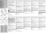
The condenser is attached to the microscope before shipment.
When removing or replacing the condenser, follow the procedure below.
(1)
Lower the condenser holder to its full limit by
rotating the condenser focus knob.
(2)
Screw in the auxiliary lens to the bottom of
the condenser.
(3)
Slide the condenser into the condenser
holder.
(4)
Position the condenser with its nameplate
facing front. Tighten the condenser clamp
screw located to the left.
(5)
Raise the condenser holder to its full limit by
rotating the condenser focus knob.
(6)
Place the blue filter in the frame provided and
insert them into the bottom of the condenser.
(7)
Focus the condenser so that light passing
through the condenser focus the image on
the correct position of the specimen (center
of the optical path).
z
Condenser focus knob
Condenser holder
Condenser
Condenser clamp screw
Auxiliary lens
Blue filter
Frame
Microscopes without the field diaphragm
Rotate the condenser focus knob to raise the condenser to its full limit and then slightly
lower it to the position where the diffuser image can no longer be seen in the viewfield.
z
Microscope with the field diaphragm
(7-1) Focus on the specimen with the 10x objective.
(7-2) Close the field diaphragm to its minimum aperture by rotating the field diaphragm
ring.
(7-3) Focus the field diaphragm image on the specimen surface by rotating the
condenser focus knob.
(7-4) Center the field diaphragm image in the viewfield of the eyepiece by manipulating
the centering screws.
(7-5) Change to the 40x objective and focus on the specimen by rotating the fine focus
knob.
(7-6) Focus the field diaphragm image on the specimen surface by rotating the
condenser focus knob.
70