1
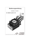
Bedienungsanleitung Compact Control 45 Best.-Nr. 7224, Compact Control 100 Best.-Nr. 7229
und Compact Control 80 HV Best.-Nr. 7228
Herzlichen Glückwunsch zum Kauf des vielseitigen brushless Reglers für Bürstenlose Motoren von Graupner. Bürstenlose Antriebe bieten
eine hohe Leistung und hohen Wirkungsgrad bei geringem Gewicht und kleinen Abmessungen. Eine erfolgreiche Anwendung setzt aber die
Einhaltung bestimmter Grundsätze voraus.
Lesen Sie bitte vor der Inbetriebnahme diese Bedienungsanleitung aufmerksam durch.
Warnhinweise:
- Das CE-Zertifikat des Reglers entbindet nicht der Verpflichtung, äußerste Vorsicht zu wahren.
- Sollte der Motor einmal nicht wie gewünscht anlaufen oder bei einem Absturz stellen Sie den Senderknüppel sofort auf Motorposition aus,
um eine Überlastung des Reglers zu vermeiden. Überprüfen Sie noch mal den richtigen Anschluss des Motors, kürzen Sie eventuell die
Kabel und stellen Sie bei Bedarf am Sender eine Zeitverzögerung für die Gasannahme ein, um Timingfehler zu verhindern.
- Benutzen Sie nur Motoren von GM-Racing oder Graupner, die für den verwendeten Spannungsbereich vorgesehen sind!
- Verwenden Sie nur Hochleistungsakkus von GM-Racing oder Graupner. Akkus mit einem zu hohen Innenwiderstand können zur
Zerstörung des Reglers führen! Benutzen Sie auf keinen Fall ein Netzteil für die Stromversorgung!
- Lassen Sie Ihr RC-Modell niemals unbeaufsichtigt, solange ein Akku angesteckt ist. Im Falle eines Defektes, könnte dies Feuer am Modell
oder seiner Umgebung verursachen.
- Der Fahrtenregler oder andere elektronische Komponenten dürfen niemals mit Wasser in Berührung kommen. Der Fahrtenregler ist vor
Staub, Schmutz, Feuchtigkeit, Vibration und anderen Fremdteilen zu schützen.
- Sie dürfen niemals den Motor mit einem separaten Akku laufen lassen. Dies zerstört den Regler und Motor und führt zum Verlust der
Garantie.
- Verpolen Sie Ihren Regler nicht. Benutzen Sie verpolsichere Stecksysteme. Vermeiden Sie Kurzschlüsse und blockierende Motoren.
- Alle Kabel und Verbindungen sollen gut isoliert sein. Kurzschlüsse können zur Zerstörung Ihres Reglers führen.
- Nicht für Kinder unter 14Jahren, kein Spielzeug!
- Die Regler sind ausschließlich für den Einsatz in Batterie- bzw. Akkubetriebenen, funkferngesteuerten Modellen vorgesehen, ein
anderweitiger Betrieb ist nicht zulässig. Der Gebrauch in einem Modell zur Personenbeförderung ist verboten!
- Motoren, Getriebe, Schiffs- oder Luftschrauben sind gefährliche Gegenstände. Halten Sie sich daher niemals neben oder vor dem
Gefährdungsbereich des Antriebes auf!
- Technische Defekte mechanischer oder elektronischer Teile können zum unverhofften Anlaufen des Motors und herumfliegenden Teilen
führen, die erhebliche Verletzungen verursachen können.
- Führen Sie immer zuerst einen Reichweitetest und Funktionstest am Boden durch (halten Sie dabei Ihr Modell fest), bevor Ihr Modell zum
Einsatz kommt. Wiederholen Sie den Test bei laufendem Motor und mit kurzen Gasstößen.
- Es dürfen keinerlei Veränderungen am Regler durchgeführt werden, es sei denn, diese sind in der Anleitung beschrieben.
- Haftungsausschluss: Sowohl die Einhaltung der Montage- und Bedienungsanleitung, als auch die Bedingungen und Methoden bei
Installation, Betrieb, Verwendung und Wartung des Fahrtenreglers können von der Fa. Graupner nicht überwacht werden. Daher übernimmt
die Fa. Graupner keinerlei Haftung für Verluste, Schäden oder Kosten, die sich aus fehlerhafter Verwendung und Betrieb ergeben, oder in
irgendeiner Weise damit zusammenhängen.
- Es dürfen nur von uns empfohlene Komponenten und Zubehörteile verwendet werden. Verwenden Sie nur zueinander passende, Original
GRAUPNER - Steckverbindungen und Zubehörteile.
- Vergewissern Sie sich vor jeder Inbetriebnahme bevor Sie den Fahrtenregler einstecken, dass: Ihr Sender als einziger auf der Frequenz
Ihres Empfängers sendet und Ihr Sender eingeschaltet ist und der Gashebel auf der Position STOP steht.
Anschlüsse des Drehzahlstellers:
Löten Sie an die Akkukabel des Fahrtenreglers Stecker vom Typ G3,5 Best.-Nr. 2970 und verwenden Sie das Kunststoffteil Best.-Nr. 2969.K
für den Verpolungsschutz oder G6 Stecker Best.-Nr.2968. Benutzen Sie grundsätzlich nur neue Stecker. Wir empfehlen ausschließlich diese
Steckertypen. Die Kabel zum Antriebsakku dürfen insgesamt max. 20cm lang sein.
Der Drehzahlsteller wird mit dem Motor mit Buchsen vom Typ G3,5 verbunden. Dabei werden an den drei Kabeln des Drehzahlstellers G3,5
Buchsen Best.-Nr. 2969 verwendet. Am Motor sollen die Stecker G3,5 Best.-Nr. 2970 angebracht sein/werden.
Einbau ins Modell und Inbetriebnahme:
Der Motor wird mit Schrauben am Motorspant befestigt. Verwenden Sie nur in der Länge passende Schrauben oder verwenden
Sie Unterlegscheiben. Beim Anziehen von zu langen Schrauben werden Sie den Motor mit Sicherheit zerstören.
Den Drehzahlsteller montieren Sie so im Modell, dass die Kühlfläche frei bleibt. Sorgen Sie für ausreichende Kühlung des
Motors und des Drehzahlstellers durch reichlich dimensionierte Kühlluftöffnungen.
1.
Richtige Verkabelung des Motors prüfen.
2.
Schalten Sie den Sender ein und überprüfen Sie den Weg des Motordrossel-Kanals, der +/- 100% und bei Multiplex
Fernsteueranlagen +/- 80% sein sollte. Bei Robbe/Futaba muss der „Gasweg“ umgedreht werden (REVERSE)! Bei
Graupner/JR muss dieser auf „NORMAL“ eingestellt sein. Der Gashebel muss auf der Position „Bremse“ bzw. „Motor
aus“ stehen!
3.
Sender einschalten („EIN“), dann den Gashebel in Stellung „Motor aus/Bremse“ bringen.
4.
Antriebsakku mit richtiger Polarität an den Regler anschließen. (Best.-Nr. 7228: Danach Empfängerakku an den Empfänger
anschließen.)
5.
Der Brushless-Motor zeigt jetzt mit 3 Signaltönen an, dass die Regelung des Reglers aktiviert ist, d.h. dass der Regler die
Kontrolle übernommen hat; gleichzeitig hat der Regler das Steuersignal vom Sender erhalten. Wenn der REGLER kein Signal
vom Sender erhält, sendet der Brushless-Motor keine akustische Einschaltbestätigung.
6.
Es erfolgt vom Regler eine Bestätigung, dass der Start sicher ist, in Form einer BeBe-BeBeep -Tonfolge. Andernfalls wartet der
Regler, bis der Benutzer den Gashebel auf die Position „Motor aus/Bremse“ zurückstellt, dass der Motor sicher anlaufen kann..
Wenn der Gashebel beim Einstecken des Fahrakkus in der Position „Vollgas“ steht, gelangt man in die Betriebsart Einstellungen,
siehe Betriebsart Einstellungen.
7.
Sie können jetzt starten und den Flug genießen.
Behandeln Sie das Modell nach Anschluss des Antriebsakkus mit größter Vorsicht, denn ein willkürliches Anlaufen der
Luftschraube kann nicht ausgeschlossen werden.
Die Umkehr der Motordrehrichtung wird durch Vertauschen von zwei der drei Motorkabel erzielt.
Der Drehzahlsteller enthält eine Schaltung, die den Verlauf und die Höhe der Akkuspannung auswertet und die Drehzahl begrenzt
und den Motor sanft abschaltet. Es können NiCd, NiMH, LiPo und LiIo Akkus verwendet werden.
-
1.
2.
3.
4.
5.
6.
7.
8.
9.
Bestandteil des Stellers ist auch ein Übertemperaturschutz, der den Motor bei Erreichen einer Temperatur des Stellers von ca.
110°C abschaltet.
Der Steller ist weiterhin mit Schutzfunktionen ausgestattet, die das richtige Anlaufen sowie den Lauf des Motors im gesamten
Bereich der verwendbaren Drehzahlen und Ströme sicherstellen. Sollten trotzdem Timingfehler (lautes Motorkreischen) auftreten,
so muss am Sender eine Zeitverzögerung der Gasannahme programmiert werden oder ein anderer Motor verwendet werden.
Betriebsart Einstellungen:
Richtige Verkabelung des Motors prüfen.
Sender einschalten („EIN“), dann den Gashebel in die Position „Vollgas“ bringen.
Antriebsakku mit richtiger Polarität an den Regler anschließen. (Best.-Nr. 7228: Danach Empfängerakku an den Empfänger
anschließen.)
Der Brushless-Motor zeigt jetzt mit 6 einzelnen Signaltönen an, dass der Regler eingeschaltet ist und dass der Benutzer die
Betriebsart Einstellungen des Reglers angewählt hat. Gleichzeitig speichert des Regler die „Vollgas“ Gashebel-Stellung ab und
stellt daraufhin die Gasstellung und den Servoweg ein.
Stellen Sie nun den Gashebel in die Position („Motor aus/Bremse“), damit der Regler diese Gasstellung speichern und
dementsprechend die Gasstellung und den Servoweg einstellen kann. Sobald die Einstellungen vollständig vorgenommen sind,
sendet der Regler den Bestätigungston BeBe-BeBeep.
Danach schaltet sich der Regler in die Betriebsart Optionsfunktionen (zusätzliche Einstellungen), wobei er jede Option mit
gesonderten Tönen bestätigt. Jedes Mal, wenn der Benutzer eine bestimmte Funktion anwählt, muss er auf den entsprechenden
Ton warten und dann den Gashebel in die Position „Vollgas“ bringen, um die Programmierung abzuspeichern. Dann sendet der
Regler die Pieptöne zur Bestätigung. Immer wenn der Benutzer einen solchen Einstellvorgang abgeschlossen hat, muss er den
Gashebel in die Position „Motor aus/Bremse“ bringen, um die nächste Einstellfunktion aufzurufen.
In der Betriebsart Funktionseinstellungen sind verschiedene Töne zu hören – lang und kurz. Der lange Ton verweist auf die
Anwahl einer bestimmten Funktion, der kurze Ton zeigt die Änderung der Einstellung für diese Funktion an. Beispiel: 2 lange
und 3 kurze Töne bedeuten, dass die zweite Funktion mit ihrer dritten Dateneinstellung an der Reihe ist.
Wenn die Einstellungen beendet sind stecken Sie den Antriebsakku ab.
Inhaltliche Bedeutung der Funktionen:
Funktion 1 – Schutz der Batterie
1-1 Hohe Abschaltspannung für LiPo/LiIo-Akkus (3,2V Abregelung, 2,9V Abschaltung)
1-2 Standard Abschaltspannung für LiPo/LiIo-Akkus (2,9V Abregelung, 2,6V Abschaltung)
1-3 Niedrige Abschaltspannung für LiPo/LiIo-Akkus (2,6V Abregelung, 2,3V Abschaltung)
1-4 Abschaltspannung bei ca. +5V für NiMH/NiCd-Akkus
Funktion 2 – Motor-Timing
2-1 Auto-Timing für Brushless-Motoren
2-2 Soft-Timing für Brushless-Motoren (für 2-polige Inline Motoren)
2-3 Standard-Timing für Brushless-Motoren
2-4 Hartes Timing für Brushless-Motoren (für Außenläufer, „slotted“ Motoren, Motoren ab 8 Pole)
Funktion 3 – Regelgeschwindigkeit der Gasannahme
3-1 Soft
3-2 Standard
3-3 Schnell
Funktion 4 – Kontrolle des Bremsverhaltens
4-1 keine Bremse
4-2 Soft-Bremse
4-3 Hartes Bremsen
Funktion 5 – Modellmodus
5-1 Betriebsart Flächenmodell/Normal
5-2 Betriebsart Heli mit Drehzahlregelung (s. Hinweis 1)
5-3 Betriebsart Heli ohne Drehzahlregelung (s. Hinweis 1)
Hinweis 1:
Im der Betriebsart Heli mit Drehzahlregelung 5-2 muss nach der Einstellung der Betriebsart die max. Drehzahl eingelernt werden.
Achtung, der Motor läuft dabei bis zur max. Drehzahl. Es sollten daher die Rotorblätter abmontiert sein, oder das Motorritzel
entfernt sein. Sorgen Sie für einen festen Halt des Modells und halten Sie sich außerhalb des Gefahrenbereich auf!
Gehen Sie nun wie folgt vor:
Gashebel (Schieberegler) nach der Auswahl der Betriebsart 5-2 wieder in die Position „Motor aus/Bremse“ bringen, um den
Regler zu aktivieren.
Gashebel (Schieberegler) in die Position „Vollgas“ bringen. Der Motor läuft nun automatisch hoch, bis er die max. Drehzahl
erreicht. Danach schaltet der Regler den Motor automatisch wieder aus. Die Programmierung ist nun beendet. Stecken Sie nun
den Antriebsakku ab.
Da in der Betriebsart Heli (Hubschrauber) eine Soft-Start Funktion eingestellt ist, schaltet der Regler das Gas nur langsam innerhalb von 3
Sekunden aus, wenn der Benutzer den Geber auf „Motor aus“ stellt. Dadurch soll verhindert werden, dass es zu einem Crash kommt, wenn
der Benutzer unvorsichtigerweise den Geber auf „Motor aus“ stellt, so dass der Motor wieder anlaufen kann und der Flug fortgesetzt werden
kann.
Verwenden Sie in dem Heli Modus mit Drehzahlregelung für die Einstellung der geregelten (= konstant gehaltenen) Drehzahl einen von der
Gas-/Pitchmischung unabhängigen Kanal mit daran angeschlossenem Schiebe- oder Drehpoti (Geber).
Achtung! Landen Sie Ihr Modell sofort, wenn die Motordrehzahl aufgrund zu abfallender Akkuspannung nachlässt. Es bleibt Ihnen
nur wenige Sekunden Zeit, um dass Modell zu landen, bevor der Motor ganz abgestellt ist. In diesem Fall muss dass Modell mit
Autorotation gelandet werden. Wenn Sie die niedrige Abschaltspannung für LiPo-Akkus wählen bleibt Ihnen etwas mehr Zeit.
Wenn Sie jedoch dann fliegen, bis der Regler abregelt bleibt dafür umso weniger Zeit zum Landen.
Wenn Sie das gesamte Einstellungsprogramm abgeschlossen haben, stecken Sie den Antriebsakku ab und schalten Sie den Sender wieder in
Betriebsart Standard an, um den Motor zu starten. Wenn Sie als Benutzer nur ein bestimmtes Programm (=eine Funktion) geändert haben,
bleiben alle übrigen Programme bei ihren vorherigen Einstellungen.
Werkseinstellungen:
1-2 Standard Abschaltung für LiPo/LiIo-Akkus
2-1 Auto-Timing
3-2 Standard-Reaktionszeit
4-2 Soft-Bremse
5-1 Betriebsart Flächenmodell
Viele angenehme Flugstunden wünscht Ihnen Graupner GmbH & Co. KG!
EG-Konformitätserklärung:
Für die folgende bezeichneten Erzeugnisse
Compact Control 45 Best.-Nr. 7224
Compact Control 100 Best.-Nr. 7229
Compact Control 80 HV Best.-Nr. 7228
wird hiermit bestätigt, dass es den wesentlichen Schutzanforderungen entspricht, die in der Richtlinie des Rates zur Angleichung der
Rechtsvorschriften der Mitgliedstaaten über die elektromagnetische Verträglichkeit 2004/108/EC
festgelegt sind.
Zur Beurteilung des Erzeugnisses wurden folgende Normen herangezogen:
EN 61000-6-1
EN 61000-6-3
Diese Erklärung wird verantwortlich für den Hersteller/Importeur
Graupner GmbH & Co. KG
Henriettenstr. 94-96
73230 Kirchheim/Teck
abgegeben durch den Geschäftsführer Hans Graupner
73230 Kirchheim/Teck, den
14.10.08
Unterschrift
Instruction Manual Compact Control 45 Order.-No. 7224, Compact Control 100 Order.-No. 7229 and Compact
Control 80 HV Order.-No. 7228
Congratulations for buying this state of the art brushless speed controller. It is adapted for use with high efficient and powerful brushless
motors.
Important notice:
Please read this manual carefully before using your controller. Only then can you have full profit of the potential of your controller,
and avoid mistakes.
Warnings:
- The controller's CE certificate doesn't unbind users from their obligation to use ultimate caution
- Should the motor refuse to start up, or after a crash, then you should immediately set the transmitter's control stick to the OFF position to
avoid any overload to the controller.
- Use only motors delivered by GM-Racing or Graupner which are designed for the intended range of voltages!
- Use only high performance batteries by Graupner or GM-Racing. Using batteries with an increased internal resistance may lead to
the
destruction of the controller! Do never use a power supply.
- Never leave your transmitter unattended when a battery is connected. In case of a deficiency this may cause an outbreak of fire on the
model or its environment.
- Neither the controller nor any other electronic components should ever come in touch with water. Protect the controller against dust, dirt,
humidity, vibrations, or other dangerous elements (with the exception of water-sealed controllers).
- Never run the motor on a separate battery. This will destroy the controller or the motor, and leads to the loss of our warranty.
- Never mix up polarities. Use plug systems which offer protection against wrong polarity. Avoid short-circuiting and blocking the motors.
- All cables and connectors should have good insulation. Short-circuits may lead to the destruction of your motor.
- This product isn't designed for use by children under the age of 14, it isn't a toy!
- Graupner-controllers are designed for use in battery-driven, radio-controlled models only, any other use is not permissible. Using this
device on a passenger-carrying model is forbidden!
- Motors, gears or gearboxes, and propellers are dangerous objects. Never keep next to or in front of the danger area of the drive!
- Technical defects or failures of mechanical or electronic parts may lead to an unexpected start-up of the motor, with parts of it flying off,
maybe causing severe injuries.
- Always check the service range of transmission of your model first thing while it's still on the ground (hold the model tightly!). Try again
with motor on and also with fast changes of the throttle stick.
- Don't make any changes on the structure and design of your controller unless they are described in the manual!
- Limited warranty: Graupner Ltd cannot survey the proper application of the mounting and using regulations, nor the working methods and
conditions during the installation, use, operation, and servicing of the controller. Therefore Graupner Ltd cannot take on any liability for any
loss, damage, or costs resulting from an incorrect use or operation of the product, or connected in any
way with incorrect use or operation.
- Only those components and accessory parts which have been recommended by us may be used. Use only genuine and matching Graupner
connectors and accessory parts.
- Make sure whenever you start connecting and operating the controller, that:
- your transmitter is the only one working on that frequency,
- is switched on,
- and has the throttle set to position “STOP”.
- Use only high-quality batteries by Graupner or GM-Racing. Cheap or old batteries with a high internal resistance may lead to poor
performance or even to the destruction of the controller.
Connecting the speed controller:
We recommend to solder G3.5 Order.-No. 2970 gold plugs to the battery wires and use Order.-No. 2969.K for wrong polarity protection or
G6 gold plugs Order-No. 2968. Always use new connectors. We do not recommend using any other type of connector. The wires to the
battery should be over all maximum 20cm long.
The speed controller should be connected to the motor with gold connectors G3.5. Use G3.5 female Order-No. 2969 for the speed controller
motor wires. Use G3.5 gold plugs female Order-No. 2970 on the motor wires.
Installing into the model:
Attach the motor to the motor mount using the screws provided. Adjust the effective screw length (place washers under the head)
so that the threads do not protrude protruding inside the motor casing. The winding of your motor can be damaged, if the screws
protrude inside the motor case. See motor instructions.
Mount the speed controller in the model so that it is isolated from vibration and shock and make sure the heatsink is free for best
cooling. Make sure that there is sufficient cooling of the motor and speed controller by directing adequate cooling air from the
outside airflow.
Setting the Standard Mode / First operation
1.
2.
3.
4.
5.
Make sure all the cable leads are properly connected.
Turn the transmitter on and check the servo travel of the throttle channel which should be ±100% or, with Multiplex R/C systems,
±80%. Robbe/Futaba systems need reversing (REVERSE) the throttle arm travel! With Graupner/JR systems, the latter should be set to
“NORMAL”. The throttle trigger should now be either at position “Brake” or at “Motor off”!
Turn the transmitter on (position “ON”), then push the throttle lever into position “Motor off / Brake”.
Connect the propulsion battery to the controller, mind the correct polarity. Plug in the power battery and try only once to plug in. Do
not touch the contact several times. (Order.-No. 7228 Connect now the receiver pack to the receiver)
The Brushless Motor will now indicate that the controller has been activated, i.e. the controller has received the control signal and the
controller has taken on full control, by sending out 3 signal sounds. If the controller doesn’t receive a control signal from the transmitter
no audible confirmation will be heard.
6.
7.
As soon as the throttle lever is now set back to position “Motor off/Brake” the controller will send out acoustic “BeBe BeBeep”signals confirming that the motor start is now safe. Otherwise the controller will wait for the user to push the throttle lever back to the
position “Motor off/Brake” before the motor can safely start. If the throttle lever is set to position “Full throttle” when plugging in the
drive battery the controller will enter the “Settings” mode – see Mode “Settings”.
You may now take off and enjoy your flight.
Handle the model with great caution when the drive battery is connected as it cannot be excluded that the propeller re-starts
unexpectedly.
Reversing the rotational sense of the motor can be achieved by swapping two of the three cable leads.
The controller contains a circuit which evaluates the progression an amount of the tension of the battery, limits the RPMs, and
initiates a soft-off of the motor. You may use batteries of the types LiPo, LiIo, NiMH, and NiCd.
Another coponent of the controller is an over-heating protection which cuts the motor when the controller reaches a temperature of
~100°-110°C.
The controller is also equipped with protective functions which assure a correct motor start as well as a smooth running of the
motor over the whole range of usable RPMs and the full torque range. However, should any timing errors turn up (loud screaming
of the motor), a time delay for accepting throttle commands must be programmed, or another motor should be installed.
Operation mode Settings:
1.
Make sure all the cable leads are properly connected.
2.
Turn the transmitter on (position “ON”), then push the throttle lever into the position “Full Throttle”.
3.
Connect the propulsion battery to the controller, mind the correct polarity. (Order.-No. 7228 Connect now the receiver pack to the
receiver)
4.
The brushless motor will now indicate with 6 acoustic signals that the controller is switched on, and that the user has selected the
operation mode settings. At the same time the controller will save the position of the throttle lever at full throttle, and adjust the
throttle position and the servo travel.
5.
Now push the throttle lever into the position “Motor off/Brake” to allow the controller to save these throttle settings, and set up the
throttle position and the servo travel accordingly. As soon as the setting process is completed the controller will acknowledge by
sending out the confirmation signal “BeBe BeBeep”.
6.
When this is done the controller will enter the operation mode “Optional functions” where it will acknowledge each function with
individual beep-signals. Whenever the user selects a special function he must wait for the corresponding signal before pushing the
throttle lever into the position “Full Throttle” in order to save the settings. The controller will then send out the beep-signals for
confirmation. Whenever the user has finished such a set-up procedure he will have to push the throttle lever into the position “Motor
off/Brake” to call up the following set-up function.
7.
In the function mode several sound signals can be heard – long and short. The long sound indicates that a special function has been
selected, whereas the short sound indicates that changes in the settings of this function have been made.
8.
Disconnect the battery when all settings are completed.
9.
Meanings of the functions:
Function 1 – battery protection
1-1 High disconnecting tension for LiPo/LiIo batteries
(3.2V deregulation, 2.9V cut-off)
1-2 Standard disconnecting tension for LiPo/LiIo batteries
(2.9V deregulation, 2.6V cut-off)
1-3 Low disconnecting tension for LiPo/LiIo batteries
(2.6V deregulation, 2.3V cut-off)
1-4 Disconnection at approx. +5V for NiMH/NiCd batteries
Function 2 – motor timing
2-1 auto timing for brushless motors
2-2 soft timing for brushless motors (for 2-pole inline motors)
2-3 standard timing for brushless motors
2-4 hard timing for brushless motors
(for outside rotor motors, slotted motors, and motors of 8 poles or more)
Function 3 – throttle speed
3-1 soft
3-2 standard
3-3 fast
Function 4 – brake control
4-1 no brake
4-2 soft brake
4-3 hard brake
Function 5 – model mode
5-1 operation mode airplane model / normal
5-2 operation mode helicopter with RPM control (see note 1)
5-3 operation mode helicopter without RPM control (see note 1)
Note 1: If you select “Heli” mode with speed governor (5 - 2), the unit has to learn the maximum rotational speed once the mode has been
set.
Caution: the motor will run up to maximum speed during this procedure, and the rotor blades or the motor pinion should therefore be
removed. Ensure that the model is securely held, and keep well away from the hazard zone.
This is the procedure:
- After selecting mode 5 – 2, move the throttle lever (slider control) back to the “motor off / brake” position in order to activate the
controller.
- Move the throttle lever (slider control) to the “full throttle” position. The motor automatically runs, accelerating until it reaches maximum
rotational speed. The controller will now automatically switch the motor off again, and the programming procedure is complete. You can
now disconnect the flight battery.
Since, in the operation mode helicopter, a soft start-up function is programmed the controller will cut the throttle only slowly, within 3
seconds, when the user pushes the throttle lever to the position “Motor off”. The idea is to prevent a crash which might occur when a user
carelessly pushes the throttle lever to the position “Motor off”. Through this device the motor may be re-started, and the flight may be
continued.
Caution! Bring your plane at once back to the airfield if the motor RPMs drop as the battery tension drops. There will only few
seconds be left to land the plane before the motor finally cuts. In this case the model must be landed in autorotation. If, however, you
select a lower deregulation tension for LiPo batteries you’ll have a little more time at your disposition. If, however, you carry on
flying until the controller disconnects you’ll have all the less time for landing.
After finishing the whole setup programme, disconnect the battery and turn the transmitter on again, in standard mode, to start the motor.
When you’ve changed only one function all the others will keep their former settings.
Factory settings:
1-2 Standard disconnecting tension for LiPo/LiIo batteries
2-1 auto timing for brushless motors
3-2 standard reaction time
4-2 soft brake
5-1 operation mode airplane model / normal
-
-
-
Warning: Once the main power pack is connected, handle the model with extreme care – Ensure that everyone is well clear
of the propeller at all times. Rotating propellers are extremely dangerous!
Connect the main power pack just before the flight and disconnect it immediately after landing.
If the motor does turn the wrong way, exchange the position of two of the three motor wires connections.
These controllers have automatic cut off with auto detection for the number and type of cells. This circuit provides the correct cut
off for all types and number of cells. The speed controller automatically provides a gradual low voltage motor cut-off. A gradual
low voltage motor cut-off is preferable with an aerobatic or HELI model to avoid a sudden loss of power which would inevitably
happen down wind and at low altitude.
Temperature overload protection is built into the speed controller which turns off the motor when the temperature reaches 110°C.
This speed controllers are equipped with protection functions that take care of the correct start and operation of the motor across
the whole range of revolutions and current. Do not connect the speed controller to just ‘any’ kind of power source. Take care to
ensure the correct polarity of NiCd, NiMH, LiIo or LiPo power packs. Your speed controller will be severely damaged if it is
connected to a battery using the wrong polarity.
Graupner GmbH & Co. KG wishes you many safe flights and happy landings.
EG declaration of conformity
for the products
Compact Control 45 Order.-No. 7224
Compact Control 100 Order.-No. 7229
Compact Control 80 HV Order.-No. 7228
We confirm that the electromagnetic compatibility directives 2004/108/EC are met.
Harmonized standards applied:
EN 61000-6-1
EN 61000-6-3
Graupner GmbH & Co. KG
Henriettenstr. 94-96
73230 Kirchheim/Teck
Managing Director Hans Graupner
73230 Kirchheim/Teck, 14.10.08
Signature
Instructions d’utilisation pour les régulateurs Compact Control 45, Réf. N°7224, Compact Control 100, Réf. N°7229 et
Compact Control 80 HV, Réf. N°7228.
Félicitations pour votre acquisition d’un régulateur Graupner pour les moteurs Brushless Les propulsions avec un moteur Brushless offrent
une très grande puissance et un haut rendement pour un faible poids et de petites dimensions.
Veuillez lire attentivement ces instructions d’utilisation avant la mise en service.
Avertissements :
Le certificat CE du régulateur ne dispense pas de prendre des précautions d’utilisation.
Si le moteur ne démarre pas comme souhaité ou après un crash, ramenez immédiatement le manche des gaz sur la position moteur
coupé pour éviter une surcharge au régulateur. Vérifiez à nouveau le raccordement correct du moteur, raccourcissez
éventuellement les fils d’alimentation et réglez au besoin un temps de retardement de la mise des gaz dans l’émetteur pour éviter
une erreur de calage.
Utilisez uniquement des moteurs de la marque GM-Racing ou Graupner pour lesquels la plage des tensions utilisées est prévue !
Utilisez uniquement les accus de haute puissance GM-Racing ou Graupner. Les accus avec une résistance trop élevée peuvent
conduire à la destruction du régulateur ! N’utilisez en aucun cas un transformateur de courant secteur pour l’alimentation !
Ne laissez jamais votre modèle R/C sans surveillance tant qu’un accu de propulsion est connecté. Dans le cas d’une défectuosité,
le modèle peut prendre feu et le communiquer à son environnement.
Les régulateurs ou les autres éléments électroniques ne doivent jamais venir en contact avec l’eau. La régulateur devra être
protégé de la poussière, des salissures, de l’humidité, des vibrations et d’autres corps étrangers.
Ne faites jamais tourner le moteur avec un accu séparé. Ceci détruira le régulateur et le moteur et conduira à la perte du bénéfice
de la garantie.
N’inversez jamais les polarités du régulateur ; utilisez un système de connecteurs avec sécurité contre les inversions de
polarité .Evites les court-circuits et les blocages du moteur.
Tous les fils et les raccordements devront être bien isolés ; un court-circuit pourra détruire le régulateur
Cet appareil ne convient pas aux enfants en dessous de 14 ans, ce n’est pas un jouet !
Le régulateur est exclusivement prévu pour l’équipement des modèles radiocommandés avec une alimentation par des accus.
toute autre utilisation n’est pas admissible !
Les moteurs, les réducteurs, les hélices marines ou aériennes sont des objets dangereux. Pour cette raison, ne vous tenez jamais à
côté ou devant la zone dangereuse des propulsions !
Une défectuosité mécanique ou électrique inopinée au démarrage du moteur peut provoquer la projection de pièces et causer de
sérieuses blessures.
Effectuez toujours d’abord un essai de porté et des fonctions au sol avant de faire voler votre modèle (en le maintenant
fermement !). Répétez ces essais avec le moteur en marche, avec de courts passages à plein gaz.
Aucunes modifications ne devront être apportées sur le régulateur, mises à part celles décrites dans ces instructions.
Exclusion de responsabilité : Le respect des instructions de montage et d’utilisation, aussi bien que les conditions et les méthodes
d’installation, d’utilisation et d’entretien ne peuvent pas être surveillées par la Firme Graupner. Pour cette raison, la Firme
Graupner décline toute responsabilité pour les pertes, les dégâts ou les coûts survenus à la suite d’une mauvaise utilisation, ou sa
participation d’une façon quelconque aux dédommagements.
Il conviendra d’utiliser uniquement les composants et les accessoires que nous conseillons. Utilisez uniquement des connecteurs
et des accessoires d’origine GRAUPNER adaptés entre-eux .
Avant de connecter votre régulateur, assurez-vous que votre émetteur est le seul à émettre sur la fréquence que vous utilisez et
avant de le mettre en contact, que le manche des gaz est sur la position STOP.
Raccordement du régulateur:
Soudez des connecteurs mâles du type G3,5, Réf. N°2970 sur les fils du régulateur pour le raccordement à l’accu et utilisez la pièce en
plastique, Réf. N°2969.K pour la protection contre les inversions de polarités, ou les connecteurs G6, Réf. N°2968. Utilisez par principe
uniquement des connecteurs neufs. Nous conseillons exclusivement ces types de connecteurs. Le fils pour le raccordement de l’accu doivent
avoir une longueur maximale de 20 cm.
Le régulateur sera relié au moteur avec des connecteurs femelles du type G3,5. Pour cela, des connecteurs femelles G3,5, Réf. N°2969
seront soudés sur les trois fils du régulateur. Des connecteurs mâles, Réf. N°2970 seront soudés sur les fils du moteur.
Montage dans le modèle et mise en service :
Le moteur sera fixé avec des vis sur le couple-moteur. Utilisez uniquement des vis d’une longueur adaptée, ou intercalez des
rondelles plates. En montant des vis trop longueur, le moteur sera sûrement détérioré.
Montez le régulateur dans le modèle de façon à ce que la surface de refroidissement reste libre. Assurez un refroidissement
suffisant au moteur et au régulateur par des entrées d’air largement dimensionnées.
Mise au point du mode d’opération Standard / Mise en service
1.
2.
3.
4.
5.
6.
Vérifier le câblage du moteur.
Allumez l’émetteur et contrôlez le déplacement du canal des gaz, qui devrait se situer à +/- 100% ou à +/- 80% pour les systèmes
Multiplex. Pour Robbe/Futaba le déplacement doit être renversé («REVERSE»)! Avec les systèmes Graupner/JR le gaz doit être
réglé sur la position «NORMAL». La manette des gaz doit alors être sur la position «Frein» ou «moteur arrêté».
Allumez l’émetteur (position «ON») puis poussez la manette des gaz dans la position «frein / moteur arrêté».
Connectez l’accu de propulsion (pour le moteur) / les piles au variateur, avec la polarité correcte. (Réf.-N°. Connectez l’accu pour le
récepteur.)
Lorsque le variateur a assumé le contrôle du moteur Brushless celui-ci indiquera que le réglage sera désormais assuré par le
variateur en émettant 3 signaux sonores, en même temps le variateur aura reçu le signal de contrôle de l’émetteur. Si le signal de
l’émetteur n’est pas reçu par le variateur le moteur Brushless manquera d’accuser réception de manière acoustique.
Dès que la manette des gaz sera remise sur la position «frein / moteur arrêté» le variateur affirmera que le démarrage sûr est assuré
en fournissant un signal sonore «BeBe-BeBeep». Le cas échéant, le variateur attendra que l’utilisateur remette la manette des gaz
sur la position «frein / moteur arrêté» avant de permettre le démarrage sûr du moteur. Si la manette des gaz est sur la position
7.
-
«pleins gaz» au moment où l’accu de propulsion est raccordé, le mode d’opération réglage (settings) sera abordé – voir passage le
suivant.
Maintenant vous êtes libres à décoller et à vous amuser en l’air.
Manipulez le modèle avec toutes le précautions nécessaires quand l’accu de propulsion est connecté comme il n’est pas à exclure
que l’hélice démarre inopinément.
Pour renverser le sens de rotation du moteur, permutez deux des trois câbles du connecteur.
Le variateur dispose d’un circuit qui évalue la progression et le montant de la tension de l’accu, limite le régime, et produit un arrêt
souple (soft-stop) du moteur. Vous pourrez utiliser des accus NiCd, NiMH, LiPo et LiIO.
L’un des composants du variateur est une protection en surtempérature qui coupera le moteur quand le variateur atteindra une
température de ~100° à 110°C.
Le variateur dispose en plus de quelques fonctions protectrices qui assurent le démarrage correcte sur la plage entière des régimes
et des courants utilisables. Si pourtant vous tombez sur des erreurs de synchronisation (le moteur s’emballe perceptiblement timing errors) il faudra que vous programmiez un délai de l’accueil des gaz sur l’émetteur, ou que vous utilisiez un autre moteur.
Mode d’opération Réglage
1.
2.
3.
8.
Vérifier le câblage du moteur.
Allumez l’émetteur puis poussez la manette des gaz dans la position «pleins gaz».
Connectez l’accu de propulsion (pour le moteur) / les piles au variateur, avec la polarité correcte. (Réf.-N°. Connectez l’accu pour le
récepteur.)
Le variateur indiquera alors en émettant 6 signaux sonores, que le variateur est fonctionnel et que l’utilisateur a choisi le mode
d’opération «Réglage du variateur».
Ensuite, poussez la manette des gaz dans la position «frein / moteur arrêté» pour permettre au variateur de mémoriser cette position
de la manette, et de la régler, ensemble avec le déplacement du bras de servo, au fur et à mesure. Dès que ces ajustements seront
faits l’émetteur fournira le signal sonore de confirmation «BeBe-BeBeep».
Ensuite le variateur passera au mode «fonctions optionales» où il confirmera la sélection d’une option, d’un signal sonore
individuel. Il faut donc attendre jusqu’à ce que le signal se fasse entendre avant de pousser la manette des gaz dans la position
«pleins gaz» pour mémoriser cette étape de la programmation. A chaque fois que l’uilisateur a terminé une telle opération de réglage
il devra pousser la manette des gaz dans la position «frein / moteur arrêté» pour évoquer la fonction de réglage suivante.
Dans le mode «réglage des fonctions» on entendra de diverses tonalités – courtes et longues. Le signal long indique qu’une certaine
fonction a été sélectionnée, le signal court indique un changement à effectuer sur le réglage de ladite fonction. Exemple: 2 signaux
longs et 3 signaux longs signifient que la deuxième fonction, avec son troisième réglage de données, peut être ajustée.
Tous réglages terminés vous pouvez débrancher l’accu de propulsion.
9.
Significations des fonctions:
4.
5.
6.
7.
1e fonction – Protection de l’accu
1-1 Tension haute de coupure pour accus LiPo/LiIo
(déréglement à 3,2V, débranchement à 2,9V)
1-2 Tension standard de coupure pour accus LiPo/LiIo
(déréglement à 2,9V, débranchement à 2,6V)
1-3 Tension basse de coupure pour accus LiPo/LiIo
(déréglement à 2,6V, débranchement à 2,3V)
1-4 Tension de coupure pour accus NiMH/NiCd à +5V
2e fonction – Synchronisation du moteur (motor timing)
2-1 Timing automatique pour moteurs Brushless
2-2 Timing souple pour moteurs Brushless (pour moteurs à induit intérieur bipolaires)
2-3 Timing standard pour moteurs Brushless
2-4 Timing rigide pour moteurs Brushless
(pour moteurs à induit extérieur, moteurs du type slotted, moteurs à partir de 8 pôles)
3e fonction – Vitesse du réglage des gaz
3-1 Souple
3-2 Standard
3-3 Rapide
4e fonction – Réglage de l’attitude au freinage
4-1 Freins inactifs
4-2 Freins souples
4-3 Freins rigides
5e fonction – Mode Spécification du modèle
5-1 Mode Modèle d’avion/Normal
5-2 Mode Hélicoptère avec réglage du régime (voir 1è remarque)
5-3 Mode Hélicoptère sans réglage du régime (voir 1è remarque)
1è remarque: Dans le mode de fonctionnement Heli avec régulation du régime 5-2, le régime maximal devra être enregistré après le réglage
du mode de fonctionnement.
Attention, le moteur démarrera jusqu’à son régime maximal, c’est pourquoi les pales du rotor devront être démontées ou le pignon moteur
sera retiré. Assurez-vous d’un maintient ferme du modèle et tenez-vous hors des zones dangereuses.
Procédez alors comme suit :
- Après la sélection du mode de fonctionnement 5-2, placez le levier des gaz (Curseur linéaire) sur la position ‘’Moteur coupé/Frein’’ pour
activer le régulateur.
- Placez ensuite le levier des gaz sur la position ‘’Plein gaz’’. Le moteur monte alors automatiquement en régime jusqu’au régime maximal.
Le régulateur décommute ensuite à nouveau automatiquement le moteur. La programmation est alors terminée.
Déconnectez maintenant l’accu de propulsion.
Comme la fonction Démarrage souple est active dans le mode Hélicoptère le variateur dérègle les gaz doucement en trois secondes, lorsque
l’utilisateur met la manette des gaz en position «frein / moteur arrêté». Ceci doit empêcher que le modèle s’abatte quand l’utilisateur pousse
la manette sur «frein / moteur arrêté» à l’imprévu, en permettant que le moteur puisse redémarrer et que le modèle reprend son vol.
Attention: Ramenez le modèle aussitôt sur le terrain si le régime du moteur baisse, à cause d’une baisse de tension des accus. Il ne vous
resteront que peu de secondes pour atterrir avant l’arrêt complet du moteur. En ce cas-là il faudrait que le modèle se pose en auto-rotation. Si
vous sélectionnez une tension de déréglage plus basse pour vos accus LiPo vous disposerez de plus de temps de vol. Mais si vous continuez
de voler jusqu’à ce que le régulateur dérègle la tension il vous restera, en revanche, moins de temps pour l’atterrissage.
Après avoir terminé le programme complet des réglages vous débranchez l’accu et remettez en marche l’émetteur dans le mode Standard
pour démarrer le moteur. Si, dans votre qualité d’utilisateur, vous avez changé une seule fonction toutes les autres fonctions garderont les
valeurs de leurs réglages.
Fonctions préprogrammées à l’usine:
1-2 Débranchement standard pour accus LiPo/LiIo
2-1 Timing automatique
3-2 Vitesse du réglage des gaz standard
4-2 freins souples
5-1 Mode Hélicoptère
-
Après la connexion de l’accu de propulsion, manipulez le modèle avec de grandes précautions, car un démarrage imprévu de
l’hélice ne pourra pas être exclu.
L’inversion du sens de rotation du moteur sera obtenu par la permutation des trois fils d’alimentation.
Le régulateur comprend aussi une protection en sur-température qui coupe le moteur lorsque la température du régulateur atteint
env. à 110°.
Le régulateur est en outre équipé de fonctions de protection qui assurent le démarrage ainsi que le fonctionnement corrects du
moteur sur la totalité de la place des régimes utilisables. Si malgré tout une erreur de calage (Bruit de grincement du moteur) se
produit, un temps de retardement de la mise des gaz devra être programmé dans l’émetteur, ou un autre moteur devra être utilisé.
Déclaration de conformité EG :
Pour les produits suivants :
Compact Control 45 Réf. N° 7224
Compact Control 100 Réf. N° 7229
Compact Control 80 HV Réf. N° 7228
Nous confirmons que la compatibilité électronique correspond aux directives 2004/108/EC.
Normes appliquées :
EN 61000-6-1
EN 61000-6-3
Graupner GmbH & Co. KG
Henriettenstr. 94-96
73230 Kirchheim/Teck
Le Directeur d’Entreprise, Hans Graupner
73230 Kirchheim/Teck, 14.10.08
Signature
Hinweise zum Umweltschutz
Das Symbol auf dem Produkt, der Gebrauchsanleitung oder der Verpackung weist darauf hin, dass dieses
Produkt am Ende seiner Lebensdauer nicht über den normalen Haushaltsabfall entsorgt werden darf. Es muss
an einem Sammelpunkt für das Recycling von elektrischen und elektronischen Geräten abgegeben werden.
Die Werkstoffe sind gemäß ihrer Kennzeichnung wiederverwertbar. Mit der Wiederverwendung, der
stofflichen Verwertung oder anderen Formen der Verwertung von Altgeräten leisten Sie einen wichtigen
Beitrag zum Umweltschutz.
Batterien und Akkus müssen aus dem Gerät entfernt werden und bei einer entsprechenden Sammelstelle getrennt entsorgt
werden.
Bitte erkundigen Sie sich bei der Gemeindeverwaltung die zuständige Entsorgungsstelle.
Environ mental Protection Notes
When this product comes to the end of its useful life, you must not dispose of it in the ordinary domestic waste.
The correct method of disposal is to take it to your local collection point for recycling electrical and electronic
equipment. The symbol shown here, which may be found on the product itself, in the operating instructions or
on the packaging, indicates that this is the case.
Individual markings indicate which materials can be recycled and re-used. You can make an important
contribution to the protection of our common environment by re-using the product, recycling the basic
materials or recycling redundant equipment in other ways.
Remove batteries from your device and dispose of them at your local collection point for batteries.
If you don’t know the location of your nearest disposal centre, please enquire at your local council office.
Indications quand à la protection de l'environnement
Ce produit à la fin de sa durée de vie ne doit pas être mis à la poubelle, mais être remis à une collecte pour le
recycle ment d'appareils électriques et électroniques. Le symbole inscrit sur le produit, dans la notice
d'instructions et sur son emballage l'indique.
Les matériaux selon leurs reconnaissances sont réutilisables. Avec le recyclage de matériaux et autres formes
d'appareils, vous contribuez à la protection de l'environnement.
Les batteries et accus doivent être retirés de l'appareil et doivent être remis à un dépôt homologué pour ce type de produits.
Veuillez s.v.p. demander auprès de votre mairie l'adresse exacte de la collecte la plus proche de chez vous.
Indicazioni sulla protezione dell’ambiente
Questo simbolo, stampato sul prodotto o indicato nelle istruzioni per l’uso o sulla confezione, avvisa che
questo prodotto, alla fine del suo utilizzo, non deve essere gettato nel normale contenitore per l’immondizia,
ma de v’essere portato ad un punto di raccolta per il riciclaggio di materiali elettrici ed elettronici.
I materiali, ciascuno secondo le proprie caratteristiche, sono riutilizzabili. Con il riciclaggio di materiali e di
vecchie apparecchiature, potrete dare un importante contributo alla protezione dell’ambiente.
Batterie ed accumulatori devono essere rimossi dalle apparecchiature ed eliminati presso un centro di raccolta appositamente
predisposto.
Informatevi sulla dislocazione dei centri di raccolta differenziata della vostra zona.