1
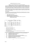
Bedienungsanleitung Brushlessregler MULTIcont BL-50 SD ! Diese Bedienungsanleitung ist Bestandteil des Produktes. Sie beinhaltet wichtige Informationen und Sicherheitshinweise. Sie ist deshalb jederzeit griffbereit aufzubewahren und beim Verkauf des Produktes an Dritte weiterzugeben. 1. SICHERHEITSHINWEISE ! ! Vor Inbetriebnahme Anleitung lesen Wärmestau vermeiden Luftzirkulation um den Regler nicht behindern ! Antriebsakku nicht verpolt anschließen Falsch gepolte Akku Anschlusskabel zerstören den Regler sofort! Deshalb: • rotes Kabel an den Plus-Pol (+) • schwarzes Kabel an den Minus-Pol (-) ! Bei Löt- und Montagearbeiten am Antrieb oder am Regler Immer den Akku abtrennen (Kurzschluss / Verletzungsgefahr!) ! Beim Probebetrieb bzw. Betrieb beachten Antrieb nicht in der Hand laufen lassen, Modell sicher befestigen. Prüfen Sie, ob ausreichend Platz zum Drehen der Luftschraube vorhanden ist. Gegenstände, die angesaugt oder weggeblasen werden können (Kleidungsstücke, Kleinteile, Papier, usw.) aus der Nähe der Luftschraube entfernen. Sich niemals vor oder in der Rotationsebene der Luftschraube aufhalten (Verletzungsgefahr!). 2. TECHNISCHE DATEN: Anleitung MULTIcont BL-50 SD # 7 2235 (16-04-13/LUNA) • Errors and omissions excepted. • MULTIPLEX Bezeichnung BL-50 SD Artikelnummer # 72235 Dauerstrom Zellenzahl max: (A) NiXX/Lipo 50A 5-18NC \ 2-6 Lipo Gewicht (g) 32 BEC Output 5.5V/ 4A Größe (mm) Programm- W*L*H ierbar 23 x 52 x 7 ja Maximale Anzahl der anschließbaren Servos an den MULTIcont BL-50 Regler im BEC mode** MULTIcont BL-50- SD Maximale Anzahl an Micro / Standardservos*: 4 * MULTIPLEX Nano-S or Tiny-S Servos. ** Falls Sie mehr Servos in Ihrem Modell einsetzen möchten, dann empfahlen wir das BEC zu deaktivieren und einen seperaten Empfängerakku einzusetzen( 7.). 3. BESONDERE EIGENSCHAFTEN Der MULTIPLEX MULTIcont BL-50 SD Regler zeichnet sich durch eine Reihe interessanter Features aus: - zahlreiche programmierbare Parameter - Unterspannungsabschaltung für: LiPo oder NiXX Akkus - Bremse: EIN oder AUS - Motordrehrichtungsumkehr: ein oder aus - Motorabschaltart: Motorleistungsreduzierung oder Motor abschalten - Motoranlaufverhalten: Soft oder Standard - Timing: automatisch oder manuell (7 Grad oder 22-30 Grad) - Taktfrequenz: 8 kHz oder 16 kHz - Modelltyp: Flächenmodell oder Hubschrauber (Governor Mode) Diese Parameter sind programmierbar über den Gasknüppel der Fernsteuerung, aber nicht mit der MULTImate # 8 2094 oder dem PC! MULTIPLEX Modellsport GmbH & Co.KG • Westliche Gewerbestraße 1 • D-75015 Bretten • www.multiplex-rc.de Page 1/6 Bedienungsanleitung Brushlessregler MULTIcont BL-50 SD 4. VERDRAHTUNG Hinweis: Bei Verwendung anderer Stecksysteme für den Anschluss eines MULTIcont BL-50 SD Reglers an Ihren Motor und / oder Akku, befolgen Sie bitte die nachfolgenden Informationen! Lötarbeiten erfordern ein Mindestmaß an Sorgfalt, da hiervon die Betriebssicherheit maßgeblich abhängt: • nur für Elektronik-Lötarbeiten geeignetes Lötzinn verwenden • kein säurehaltiges Lötfett verwenden • zu verlötende Teile nicht übermäßig, aber ausreichend erhitzen (das Zinn muss fließen) • gegebenenfalls jemanden mit Löterfahrung hinzuziehen • alle Lötstellen und blanke Kabelstellen sorgfältig isolieren (z.B. mit Schrumpfschlauch) Anschluss der Akku-Steckverbindung Die Akku-Anschlussstecker werden an den zwei Kabeln angeschlossen (rot = +, schwarz = -). Kabel möglichst kurz halten. Kürzen Sie die Akku-Anschlusskabel ggf. auf die erforderliche Länge. Schieben Sie ein Stück Schrumpfschlauch auf jedes Kabel und verschrumpfen Sie die Lötstellen nach den Lötarbeiten. Beim Anlöten der Akku-Anschlussstecker auf die korrekte Polung zum Akku achten. Falschpolung führt unweigerlich zur sofortigen Zerstörung des Reglers! Anschluss des Reglers an den Motor Der Motor wird auf der Seite mit den drei herausgeführten Kabeln angeschlossen. Löten Sie ggf. die zum Motor-Stecksystem passenden Buchsen an und isolieren Sie nach den Lötarbeiten die Lötstellen mit Schrumpfschlauch. Kabel möglichst kurz halten. Für eine evtl. notwendige Motor-Drehrichtungsumkehr tauschen Sie einfach zwei der drei zum Motor führenden Zuleitungen oder ändern die Motor-Drehrichtung durch Programmierung. Anleitung MULTIcont BL-50 SD # 7 2235 (16-04-13/LUNA) • Errors and omissions excepted. • MULTIPLEX Anschluss des dreiadrigen Anschlusskabels (UNI-Stecksystem) am Empfänger Stecken Sie das dreiadrige Empfänger-Anschlusskabel des Reglers in den Empfängereingang für die Motorregelung: - bei MULTIPLEX Fernsteuerungen i.a. an Kanal 4 = Gas / Motor - bei HiTEC Fernsteuerungen an Kanal 3 = Gas / Motor Pinbelegung Minus-Pol (−) braun Plus-Pol (+) rot Impuls ( ) orange Schließen Sie keinen zusätzlichen Empfängerakku an den Empfänger an, da der Regler den Empfänger und die Servos über sein S-BEC mit Strom versorgt. Beachten Sie immer die maximale Anzahl anschließbarer Servos im BEC Betrieb. 5. EINSTELLUNGEN: 1. Bremse ein/ aus schalten EIN –der Propeller bremst, wenn der Gashebel am Minimum ist (empfohlen bei Klappluftschrauben). AUS –der Propeller läuft frei, wenn der Gashebel am Minimum ist. 2. Akku-Typ: LiPo oder NiCd / NiMh NiCd / NiMH - Die Niederspannungs-Schutzschwelle wird für NiCd / NiMH-Zellen gesetzt. LiPo - Die Niederspannungs-Schutzschwelle wird für LiPo Zellen gesetzt und erkennt automatisch die Anzahl der Zellen im Pack. Hinweis: Wird NiCd / NiMH als Akku-Typ ausgewählt, wird automatisch die Abschaltschwelle auf 60% eingestellt. Der Schwellwert kann anschließend durch die Niederspannungs- Schutzfunktion verändert werden, falls gewünscht. Der Regler misst die anfängliche Spannung des NiCd / NiMH-Akkus, wenn er angesteckt wird und diese Spannung wird als Referenz für die Spannungsschwelle verwendet. MULTIPLEX Modellsport GmbH & Co.KG • Westliche Gewerbestraße 1 • D-75015 Bretten • www.multiplex-rc.de Page 2/6 Bedienungsanleitung Brushlessregler MULTIcont BL-50 SD 3. Abschaltcharakteristik beim Niederspannungsschutz (Low / Medium / High) 1) Bei Li-xx-Packs wird die Anzahl der Zellen automatisch berechnet und es sind bis auf die Definition des Akkutyps keine weiteren Benutzereingaben erforderlich. Der Regler bietet drei Einstellmöglichkeiten für die Niederspannungs-Schwelle; Low (2.8V) / Medium (3.0V) / High (3.2V). Beispiel der Abschaltung bei einem 3-Zellen-Lipo mit 11,1 V: 8.4V (Low) / 9.0V (Med) / 9.6V (High) 2) Bei Ni-xx Akkus bedeuten -low / medium und high- Abschaltungen 50% / 60% und 65% der anfänglichen Spannung des Akkus . Beispiel: Ein voll geladener 6 Zellen NiMh Pack hat die Spannung von 6x 1.44V 6 = 8.64V, wenn die "LOW" Abschaltspannung eingestellt ist, schaltet der Regler bei 8.64V x 50% = 4,3 V ab, bei der "Medium" bzw. "High "Einstellung ist, ist die Abschaltspannung bei 8.64V x 65% = 5.61V. 4. Werkseinstellungen wiederherstellen: Wiederherstellen- setzt den Regler auf folgende Werkseinstellungen zurück; Bremse: AUS Akku-Typ: LiPo mit automatischer Zellenerkennung Niederspannungs-Abschaltschwelle: Medium (3.0V/60%) Timing Setup: Automatisch Softanlauf: EIN Governor Mode: AUS Frequenz: 8kHz Niederspannungsabschaltung: Leistung reduzieren Anleitung MULTIcont BL-50 SD # 7 2235 (16-04-13/LUNA) • Errors and omissions excepted. • MULTIPLEX 5. Timing Einstellung: Automatisch / Low / High. Automatisch (7-30 Grad) – Der Regler bestimmt automatisch das optimale Motor-Timing Low (7-22 Grad) - Einstellung für die meisten 2-poligen Motoren. High (22-30 deg)-Einstellung für Motoren mit 6 oder mehr Polen. In den meisten Fällen funktioniert die automatische Timing gut für alle Arten von Motoren. Doch für eine höhere Effizienz empfehlen wir die low-Timingeinstellung für 2-polige Motoren (Innenläufer) und die high-Timimgeinstellung für 6 und mehrpolige Motoren (Aussenläufer). Einige Motoren erfordern aber spezielle Timing-Einstellungen daher empfehlen wir Ihnen, sich an die vom Hersteller empfohlene Einstellung zu halten, oder das automatische Timing zu wählen, wenn Sie unsicher sind. Hinweis: Testen Sie Ihren Motor zuerst im Stand, wenn Sie Änderungen am Timing vorgenommen haben! 6. Sanftanlauf- Einstellungen: sehr sanft / sanfte Beschleunigung / schnelle Beschleunigung Sehr sanfter Anlauf – Benötigt 1,5 sec von Anfang bis zur vollen Drehzahl und schützt Zahnräder vor zu hoher Belastung. Diese Einstellung wird entweder für Flächenmodelle mit Getrieben und / oder Hubschraubern empfohlen. sanfte Beschleunigung: Benötigt 1,5 sec von Anfang bis zur vollen Drehzahl. Diese Einstellung wird entweder für Flächenmodelle mit Getrieben und / oder Hubschraubern empfohlen. schnelle Beschleunigung - Ermöglicht schnelle Beschleunigung mit einem linearen Ansprechverhalten. Dies ist für Flächenmodelle mit Direktantrieb empfohlen. 7. Aktive Drehzahlsteuerung (Heli Governor mode) Govenor Mode AUS Heli G-Mode 1: Verzögerung von 5 Sekunden vom Start bis zur vollen Drehzahl Heli G-Mode 2: Verzögerung von 15 Sekunden vom Start bis zur vollen Drehzahl MULTIPLEX Modellsport GmbH & Co.KG • Westliche Gewerbestraße 1 • D-75015 Bretten • www.multiplex-rc.de Page 3/6 Bedienungsanleitung Brushlessregler MULTIcont BL-50 SD 8. Motor Drehrichtung: Vorwärts / Rückwärts In den meisten Fällen wird die Drehrichtung durch das Vertauschen zweier Motorleitungen umgekehrt. In Fällen, wo die Motorleitungen direkt an das Reglerkabel gelötet sind, kann Motordrehung im Regler umgekehrt werden. 9. Schaltfrequenz: 8kHz/16kHz - 8kHz - Schaltfrequenz für 2-polige Motoren, z.B. Innenläufer. - 16kHz - Schaltfrequenz für Motoren mit mehr als 2 Polen, z. B. Außenläufer. 10. Abschaltung: Abregelung / harter Stop - Abregelung - Regler reduziert die Motorleistung, wenn der eingestellte Schwellwert erreicht ist. (empfohlen) - harter Stop - Regler kappt sofort die Motorleistung, wenn der eingestellte Schwellwert erreicht ist. Anleitung MULTIcont BL-50 SD # 7 2235 (16-04-13/LUNA) • Errors and omissions excepted. • MULTIPLEX 6. PROGRAMIER-SCHEMA Programmier-Tonfolgen 0 Knüppelkalibrierung (innerhalb der ersten 4 sec. )●● ●● ●● ●● 1 Bremse _* _* _* _* 2 Akkutyp ~ ~ ~ ~ ~~ ~~ ~~ ~~ 3 Niederspannungs-Abschaltung *_ _* *_ _* *_ _* *_ _* *_ _ _* *_ _ _* *_ _ _* *_ _ _* *_ _ _ _* *_ _ _ _* *_ _ _ _* *_ _ _ _* 4 Restore Factory Setup Defaults — ——— 5 Timing Einstellung – – – – –– –– –– –– ––– ––– ––– ––– 6 Motorbeschleunigung Reglerfunktionen Bremse EIN / AUS NiCd LiPo Low2.8V/50% Medium3.0V/60% High3.2V/65% Wiederherstellen Automatisch (7-30°) Low (7-22°) High (22-30°) sehr sanft sanfte Beschleunigung schnelle Beschleuigung 7 8 9 10 Governor Mode _*_ _*_ _*_ _*_ _**_ _**_ _**_ _**_ _***_ _***_ _***_ _***_ Motor Drehrichtung W W W W Taktfrequenz // // // // \\ \\ \\ \\ Niederspannungsabschaltung _¯_¯_¯_¯ ¯_ ¯_ ¯_ ¯_ Govenor Mode AUS Heli G-Mode 1 Heli G-Mode 2 Vorwärts/ Rückwärts 8kHz 16kHz Leistungsreduktion Harter Stop 7. BETRIEB DES REGLERS Falsche Polarität oder Kurzschluss beschädigt den Regler. Überprüfen Sie alle Stecker auf richtige Polarität, BEVOR Sie den Akku anschließen. Warntöne: Der Regler gibt bei Fehlstellungen des Gasknüppels beim Einschalten akustische Alarmtöne aus: Kontinuierlicher Piepton (****) - Zeigt an, dass Gasknüppel nicht in der Minimum-Position ist. Zwei einzelne Pieptöne mit einer Pause von einer Sekunde (****) - Zeigt an, dass die Akkuspannung den zulässigen Bereich überschreitet. (Der Regler überprüft und verifiziert die Batteriespannung automatisch, nachdem der Akku angeschlossen wurde). MULTIPLEX Modellsport GmbH & Co.KG • Westliche Gewerbestraße 1 • D-75015 Bretten • www.multiplex-rc.de Page 4/6 Bedienungsanleitung Brushlessregler MULTIcont BL-50 SD 8. REGLER-INTEGRIERTE SICHERHEITSFUNKTIONEN: 1. Überhitzungsschutz: Wenn der regler die Temperatur von 110 ° C übersch reitet, wird die Ausgangsleistung reduziert, um ihn zu kühlen. 2. Verlorenes Gas-Signal-Schutz: Der Regler unterbricht automatisch die Stromzufuhr für den Motor, wenn das gas-Signal für mehr als zwei Sekunden unterbrochen wird und meldet das mit einem kontinuierlichen Piepton. 9. EINSCHALTEN DES REGLERS ZUM ERSTEN MAL / AUTOMATISCHE MOTOR-/GASKALIBRIERUNG Der Regler verfügt über eine automatische Motor-/Gaskalibrierung, um die volle Auflösung über den gesamten Steuerbereich des Senders (Gasknüppels) zu nützen. Dieser Schritt ist einmal zu erledigen, damit Ihr Regler den gesamten Steuerweg Ihres Senders kennt. Sie müssen diesen Schritt wiederholen, wenn Sie einen anderen Sender (einer anderen Marke)einsetzten 1.Schalten Ihren Sender ein und stellen Sie den Gashebel aus Vollgas. 2. Verbinden Sie den Akku mit dem Regler. Warten Sie ca. 2 Sekunden, der Motor piept zweimal. Bringen Sie den Gasknüppel in den Leerlauf, der Motor signalisiert nun, dass der gesamte Steuerbereich gespeichert wurde. Die „Drossel“ ist nun kalibriert und Ihr Regler ist betriebsbereit. 10. PROGRAMMIERUNG 1. Geben Sie am Sender zuerst Vollgas und schalten Sie diesen danach ein. 2. Schließen Sie den Akku an den Regler an. 3. Warten Sie, bis Sie zwei kurze Pieptöne zu hören sind. Die nachfolgende Tonfolge (● ● ● ● ● ● ● ●) bestätigt, dass der Regler sich nun im Programmiermodus befindet. 4. Sobald Sie den Gasknüppel für >5 Sec. Auf Vollgas halten, beginnt der Regler mit der Programmierung. Die Programmierung geschieht aufeinander folgend wie in der Tabelle bei Punkt 7 beschrieben. Anleitung MULTIcont BL-50 SD # 7 2235 (16-04-13/LUNA) • Errors and omissions excepted. • MULTIPLEX 5. Wenn der gewünschte Ton für die Funktion und Einstellung erreicht ist, bewegen Sie den Gashebel nach unten auf seine minimale Position. Der Regler bestätigt durch zwei Pieptöne (**) , dass die neue Einstellung gespeichert wurde. 6. Der Regler erlaubt immer nur die Einstellung von einer Funktion zu einem Zeitpunkt. Sollten Sie Änderungen an anderen Funktion benötigen, trennen Sie den Akku, und warten Sie 5 Sekunden, stecken Sie den Akku wieder an und wiederholen Sie die obigen Schritte. 11. NORMALER STARTVORGANG 1. Schalten Sie Ihren Sender ein und stellen Sie den Gashebel auf Minimum Position. 2. Schließen Sie den Akku an den Regler an. 3. Wenn der ESC zum ersten Mal eingeschaltet wird, ertönen zwei Tonfolgen, der Regler ist nun aktiviert. * Die erste Tonfolge zeigt die Zahl der ermittelten Zellen wenn ein LiPo mit dem Regler verbunden ist. (Drei Signaltöne (***) zeigen einen 3-Zellen LiPo Pack während 4 Pieptöne (****) einen 4-Zellen LiPo-Pack bedeuten). * Die zweite Tonfolge beschreibt den Brems-Status (ein Piepton (*) für Bremse "AN" und zwei Signaltöne (**) für Bremse "AUS"). Der Regler ist nun Einsatzbereit. 12. GENERELLE SICHERHEITSHINWEISE ● Entfernen Sie den Propeller oder das Antriebsritzel (Hubschrauber) am Motor, wenn Sie den Antrieb zum ersten Mal mit Ihrem Sender in Betrieb nehmen um die Einstellungen zu überprüfen. Installieren Sie nur Ihren Propeller oder Ritzel sachgemäß, nachdem Sie sich vergewissert haben, dass die Einstellungen an Ihrem Sender korrekt sind. ● Verwenden Sie niemals beschädigte Akkuzellen. ● Prüfen Sie regelmäßig Ihre Kabelverbindungen. ● Überschreiten Sie nicht die in den technischen Daten des Reglers angegebene Anzahl der Zellen oder Servos. ● Falsche Polung führt zur Beschädigung des Reglers und zum Erlöschen der Garantie. ● Installieren Sie den Regler an einem geeigneten Ort im Modell mit ausreichender Luftzufuhr für die Kühlung. MULTIPLEX Modellsport GmbH & Co.KG • Westliche Gewerbestraße 1 • D-75015 Bretten • www.multiplex-rc.de Page 5/6 Bedienungsanleitung Brushlessregler MULTIcont BL-50 SD Der Regler verfügt über eine eingebaute Übertemperatur-Abschalt-Schutz-Funktion, so dass er sofort den Motor abregelt, wenn der Regler 110 °C überschreitet. ● Verwenden Sie nur Akkutypen wie in den technischen Daten angegeben, achten Sie auf die richtigen Polaritäten der Anschlüsse. Schalten Sie immer zuerst Ihre Fernsteuerung und dann den Regler (das Modell) ein. Beim Ausschalten immer zuerst den Antriebsakku im Modell ausstecken und danach die Fernsteuerung ausschalten. ● Behandeln Sie Ihr Modell mit äußerster Vorsicht, sobald der Akku angeschlossen ist und halten Sie sich vom Propeller fern. 13. GEWÄHRLEISTUNG / HAFTUNGSAUSSCHLUSS Für unsere Produkte leisten wir entsprechend den derzeit geltenden gesetzlichen Bestimmungen Gewähr. Wenden Sie sich mit Gewährleistungsfällen an den Fachhändler, bei dem Sie das Gerät erworben haben. Von der Gewährleistung ausgeschlossen sind Fehlfunktionen, die verursacht wurden durch: • unsachgemäßen Betrieb, falsche Anschlüsse • Verwendung von nicht originalem MULTIPLEX-Zubehör • Veränderungen bzw. Reparaturen, die nicht von MUL-TIPLEX oder einer autorisierten MULTIPLEX-Service-Stelle ausgeführt wurden • versehentliche oder absichtliche Beschädigung • Defekte auf Grund normaler Abnutzung • Betrieb außerhalb der technischen Spezifikationen Die MULTIPLEX Modellsport GmbH & Co.KG übernimmt keine Haftung für Verluste, Schäden oder Kosten, die sich aus einer fehlerhaften Verwendung und dem Betrieb des Produkts ergeben oder damit zusammenhängen. Anleitung MULTIcont BL-50 SD # 7 2235 (16-04-13/LUNA) • Errors and omissions excepted. • MULTIPLEX 14. CE-KONFORMITÄTSERKLÄRUNG Die Bewertung des Gerätes erfolgte nach europäisch harmonisierten Richtlinien. Sie besitzen daher ein Produkt, das hinsichtlich der Konstruktion die Schutzziele der Europäischen Gemeinschaft zum sicheren Betrieb der Geräte erfüllt. Die Konformitätserklärung des Gerätes kann bei der MULTIPLEX Modellsport GmbH & Co.KG angefordert werden. 14. ENTSORGUNGSHINWEISE Elektrogeräte, die mit der durchgestrichenen Mülltonne gekennzeichnet sind, zur Entsorgung nicht in den Hausmüll geben, sondern einem geeigneten Entsorgungssystem zuführen. In Ländern der EU (Europäische Union) dürfen Elektro-geräte nicht durch den Hausbzw. Restmüll entsorgt wer-den (WEEE - Waste of Electrical and Electronic Equipment, Richtlinie 2002/96/EG). Sie können Ihr Altgerät bei öffentlichen Sammelstellen Ihrer Gemeinde bzw. ihres Wohnortes (z.B. Recyclinghöfe) abgeben. Das Gerät wird dort für Sie fachgerecht und kostenlos entsorgt. Mit der Rückgabe Ihres Altgerätes leisten Sie einen wichtigen Beitrag zum Schutz der Umwelt! MULTIPLEX Modellsport GmbH & Co.KG • Westliche Gewerbestraße 1 • D-75015 Bretten • www.multiplex-rc.de Page 6/6 Operating instructions MULTIcont BL-50 SD ! These operating instructions are an integral part of this product. They contain important information and safety notes, and should therefore be kept in a safe place at all times. Be sure to pass them on to the new owner if you ever dispose of the product. 1. SAFETY NOTES ! Read the instructions before using the controller ! Avoid heat build-up Provide unobstructed air circulation round the controller ! Do not connect the flight battery with reversed polarity Connecting the battery leads with reversed polarity will instantly wreck the controller For this reason: • red wire to the POSITIVE terminal (+) • black wire to the NEGATIVE terminal (-) ! When soldering or working on the motor or controller Always disconnect the battery (short-circuit / injury hazard) ! When testing and running the power system Do not run the motor while holding it in your hand; always secure the model firmly. Check that there is adequate space for the propeller to rotate. Remove all objects from the area around the propeller which could be sucked in or blown away (clothing, paper etc.). Never stand in the rotational plane of the propeller (injury hazard). 2. SPECIFICATION: Anleitung MULTIcont BL-50 SD # 82 6050 (13-03-06/BRAN) • Errors and omissions excepted. • MULTIPLEX Type BL-50 SD Idem no. Cont. Current Battery cell Weight BEC Size (mm) User (A) NiXX/Lipo (g) Output W*L*H Program 32 5.5V/ 4A 23 x 52 x 7 # 72235 50A 5-18NC \ 2-6 Lipo yes Maximum number of servos usable with MULTIcont BL-50 controllers in BEC mode** MULTIcont BL-50 Maximum number of micro / standard servos*: 4 * MULTIPLEX Nano-S or Tiny-S servo types. ** If the number of servos in the model exceeds the stated maximum, it is essential to disable the BEC system and use a separate receiver battery ( 7.). 3. SPECIAL FEATURES MULTIPLEX MULTIcont BL-50 SD controller offers an excellent range of additional features: numerous programmable parameters - low-voltage cut-off for: LiPo and NiXX batteries - brake: ON or OFF - motor reverse: on or off - motor cut-off type: motor power reduction or motor cut - motor start behaviour: soft or standard - timing: automatic or manual (7 degrees or 22 - 30 degrees) - pulse frequency: 8 kHz or 16 kHz - model type: fixed-wing or helicopter (governor mode) These parameters are programmable using the transmitter throttle stick. ! But not with the MULTIPLEX MULTImate # 8 2094 or PC. MULTIPLEX Modellsport GmbH & Co.KG • Westliche Gewerbestraße 1 • D-75015 Bretten • www.multiplex-rc.de Page 1/7 Operating instructions MULTIcont BL-50 SD 4. WIRING ! Note: if you wish to use a different connector system for connecting a MULTIcont BL-15 speed controller to your motor and / or battery, please note the following infor-mation: Soldering requires some care, as the quality of the joints is crucial to the reliability of the power system: • • • • • Use electronic-grade solder for all soldered joints Do not use acid-based solder flux Parts to be soldered must be hot enough (the solder must flow), but must not be overheated (damage to components) If you are unsure, ask a modeller with experience in soldering to help you Carefully insulate all solder joints and bare wires (e.g. using heat-shrink sleeving) Attaching the battery connectors The battery connectors have to be attached to the two wires (red = +, black = -). Keep the wires as short as possible. If necessary, cut the battery leads to the required length. Fit a piece of heat-shrink sleeve on each wire, and shrink the sleeve over the soldered joint. Take great care to maintain correct polarity when soldering the battery connectors to the leads. Reversed polarity inevitably and invariably wrecks the controller. Connecting the speed controller to the motor The motor is connected to the three wires which exit one end of the controller. Solder sockets to the wires which match the motor connectors, and insulate each soldered joint with a separate heat-shrink sleeve. Keep the leads as short as possible. If you need to reverse the direction of rotation of the motor, simply swap over two of the three wires leading to the motor; alternatively change the direction by programming ( 6.3.). Pin assignment Negative pin (−) brown Positive pin (+) red Signal ( ) orange Do not connect a separate receiver battery to the receiver, as the controller supplies current to the receiver and servos via the BEC circuit. Always keep to the maximum servo count limit in BEC mode ( 2.). Disable the BEC system if necessary 5. SETTINGS: * ON- Sets the propeller to the brake position when the throttle stick is at the minimum position (Recommended for folding props). * LiPo – Sets Low voltage protection threshold for LiPo cells and automatically detects the number of cells within the pack. Anleitung MULTIcont BL-50 SD (13-03-06/BRAN) • 1. Brake: ON/OFF # 82 6050 Errors and omissions excepted. • MULTIPLEX Connecting the three-core lead (UNI connector system) to the receiver Connect the three-core receiver lead (attached to the speed controller) to the receiver input socket used for motor speed control: - With MULTIPLEX RC systems: channel 4 = throttle / motor - With HiTEC RC systems: channel 3 = throttle / motor * OFF- Sets the propeller to freewheel when the throttle stick is at the minimum position. 2. Battery type: LiPo or NiCad/NiMh * NiCad/NiMH – Sets Low Voltage protection threshold for NiCad/NiMH cells. Note: Selecting the NiCad/NiMH option for the battery type, triggers the ESC to automatically set the cutoff threshold to the factory default of 60%. The cutoff threshold can then be subsequently altered through the Low Voltage protection function, if required. The ESC will read the initial voltage of the NiCad/NiMh pack once it is plugged in and the voltage read will then be used as a reference for the cutoff voltage threshold. 3. Low Voltage Protection Threshold ( Cutoff Threshold ): Low / Medium / High 1) For Li-xx packs- number of cells are automatically calculated and requires no user input apart from defining the battery type. This ESC provides 3 setting options for the low voltage protection threshold ; Low (2.8V)/ Medium (3.0V)/ High (3.2V). For example : the MULTIPLEX Modellsport GmbH & Co.KG • Westliche Gewerbestraße 1 • D-75015 Bretten • www.multiplex-rc.de Page 2/7 Operating instructions MULTIcont BL-50 SD voltage cutoff options for an 11.1V/ 3 cell Li-Po pack would be 8.4V (Low)/ 9.0V(Med)/ 9.6V(High) 2) For Ni-xx packs-low / medium / high cutoff voltages are 50%/60%/65% of the initial voltage of the battery pack.. For example: A fully charged 6 cell NiMh pack’s voltage is 1.44V x 6=8.64V,when “LOW” cutoff voltage is set, the cutoff voltage is: 8.64V x 50%=4.3V and when “Medium” of “High” is set, the cutoff voltage is now 8.64V X 65%=5.61V. 4. Restore factory setup defaults: Restore- Sets the ESC back to factory default settings; Brake: OFF Battery type Detect: LiPo with Automatic Cell Low voltage Cutoff threshold: Medium (3.0V/60%) Timing Setup: Automatic Soft Acceleration Start Up: Soft Acceleration Governor Mode : RPM OFF Frequency : 8kHz Low Voltage Cutoff Type: Reduce power 5. Timing Setup : Automatic/ Low / High. * Automatic (7-30 deg) – ESC automatically determines the optimum motor timing * Low (7-22 deg) – Setting for most 2 pole motors. * High(22-30 deg)-setting for motors with 6 or more poles. In most cases, automatic timing works well for all types of motors. However for high efficiency we recommend the Low timing setting for 2 pole motors (general in-runners) and high timing for 6 poles and above (general out-runners). For higher speed, High timing can be set. Some motors require different timing setups therefore we suggest you to follow the manufacturer recommended setup or use the automatic timing setting if you are unsure. Note: Run your motor on the ground first after making any changes to your motor timing! Anleitung MULTIcont BL-50 SD # 82 6050 (13-03-06/BRAN) • Errors and omissions excepted. • MULTIPLEX 6. Soft Acceleration Start ups: Very Soft / Soft Acceleration/ Start Acceleration * Very Soft – Provides initial slow 1.5 sec ramp-up from start to full rpm intended to protect delicate gears from stripping under instant load. This setting is recommended for either fixed wing models equipped with gearboxes and / or helicopters. * Soft Acceleration- Provides initial slow 1 sec ramp-up from start to full rpm. This setting is recommended for either fixed wing models equipped with gearboxes and or helicopters. * Start Acceleration – Provides quick acceleration start ups with a linear throttle response. This is recommended for fixed wing models fitted with direct drive setups. 7. Active RPM Control (Heli Governor mode) * RPM Control OFF * First Range: There will be a 5-second delay from start to full rpm, but if the throttle is cutoff after starting, then the next start will be as normal start. * Second Range: There will be a 15-second delay from start to full rpm, but if the throttle is cutoff after starting, then the next start will be as normal start. Note: Once the Governor Mode is enabled, the ESC’s Brake and Low Voltage Cutoff Type settings will automatically be reset to No Brake and Reduce Power respectively regardless of what settings they were previously set. 8. Motor Rotation: Forward/ Reverse In most cases motor rotation is usually reversed by swapping two motor wires. However, in cases where the motor cables have been directly soldered the ESC cables, motor rotation can be reversed by changing the value of setting on the ESC. 9. Switching Frequency : 8kHz/16kHz * 8kHz – Sets ESC switching frequency for 2 pole motors, e.g. in-runners. * 16kHz – Sets ESC switching frequency for motors with more than 2 poles, e.g. out-runners. Although 16kHz is more efficient with our Thrust motors, the setup. Default is 8kHz due to the higher RF noises caused at 16kHz. MULTIPLEX Modellsport GmbH & Co.KG • Westliche Gewerbestraße 1 • D-75015 Bretten • www.multiplex-rc.de Page 3/7 Operating instructions MULTIcont BL-50 SD 10. Low Voltage Cutoff Type : Reduce Power / Hard cutoff * Reduce Power – ESC reduces motor power when the pre-set Low Voltage Protection Threshold value is reached. (recommended) * Hard Cutoff – ESC instantly cuts motor power when the pre-set Low Voltage Protection Threshold value is reached. 6. PROGRAMMING MODE AUDIBLE TONES Programming Mode Audible Tones 0 Throttle Calibration (within the first 4 Sec )●● ●● ●● ●● 1 Brake _* _* _* _* 2 Battery type ~ ~ ~ ~ ~~ ~~ ~~ ~~ 3 Low Voltage Cutoff Threshold *_ _* *_ _* *_ _* *_ _* *_ _ _* *_ _ _* *_ _ _* *_ _ _* *_ _ _ _* *_ _ _ _* *_ _ _ _* *_ _ _ _* 4 Restore Factory Setup Defaults — ——— 5 Timing Setup – – – – –– –– –– –– ––– ––– ––– ––– 6 Soft Acceleration Start Ups ESC Functions Brake On /Off NiCad LiPo Low2.8V/50% Medium3.0V/60% High3.2V/65% Restore Automatic (7-30°) Low (7-22°) High (22-30°) Very Soft Soft Acceleration Start Acceleration Anleitung MULTIcont BL-50 SD # 82 6050 (13-03-06/BRAN) • Errors and omissions excepted. • MULTIPLEX 7 8 9 10 Governor Mode _*_ _*_ _*_ _*_ _**_ _**_ _**_ _**_ _***_ _***_ _***_ _***_ Motor Rotation W W W W Switching Frequency // // // // \\ \\ \\ \\ Low Voltage Cutoff Type _¯_¯_¯_¯ ¯_ ¯_ ¯_ ¯_ Rpm off Heli first range Heli second range Forward/ Reverse 8kHz 16kHz Reduce Power Hard Cut Off Using Your New ESC Improper polarity or short circuit will damage the ESC therefore it is your responsibility to double check all plugs for proper polarity and first fit BEFORE connecting the battery pack. Alert Tones The ZTW ESC is equipped with audible alert tones to indicate abnormal conditions at power up. 1. Continuous beeping tone (****) – Indicates that throttle stick is not in the minimum position. 2. Single beeping tone followed by a one second pause (* * * *)– Indicates that the battery pack voltage exceeds the acceptable range. (The ESC automatically checks and verifies the battery voltage once the battery is connected). Built-in Intelligent ESC Safety Functions 1. Over-heat protection: When the temperature of ESC exceeds 110 deg C, the ESC will reduce the output power to allow it too cool. 2. Lost Throttle signal protection: The ESC will automatically cut power to the motor when it detects a lost of throttle signal for 2 seconds, then the motor will emit continuous beeping tone. MULTIPLEX Modellsport GmbH & Co.KG • Westliche Gewerbestraße 1 • D-75015 Bretten • www.multiplex-rc.de Page 4/7 Operating instructions MULTIcont BL-50 SD 7. POWERING UP THE ESC FOR THE FIRST TIME & SETTING THE AUTOMATIC THROTTLE CALIBRATION The ZTW ESC features Automatic Throttle Calibration to attain the smoothest throttle response and resolution throughout the entire throttle range of your transmitter. This step is done once to allow the ESC to “learn and memorize” your Transmitter’s throttle output signals and only repeated if you change your transmitter. 1.Switch your Transmitter ON and set the throttle stick to its maximum position. 2.Connect the battery pack to the ESC. Wait for about 2 seconds, the motor will beep for twice, then put the throttle in the minimum position, the motor will also beep, which indicates that your ESC has got the signal range of the throttle from your transmitter. The throttle is now calibrated and your ESC is ready for operation. 8. ENTERING THE PROGRAMMING MODE 1. Switch your Transmitter ON and set the throttle to its maximum position. 2. Connect the battery pack to the ESC. 3. Wait until you hear two short beeps (●● 4. If the throttle stick is left in the maximum position beyond 5 seconds, the ESC will begin the sequence from one function and its ●● ●● ●●) confirming that the ESC has now entered the programming mode. associated setting options to another. (Please refer to the table below to cross reference the functions with the audible tones). 5. When the desired tone for the function and setting option is reached, move the throttle stick down to its minimum position. ESC will emit two beeps (**) confirming the new setting has been stored. 6. The ESC only allows the setting of one function at a time. Therefore should you require making changes to other function, disconnect the battery pack and wait 5 seconds to reconnect the battery and repeat the above steps. Anleitung MULTIcont BL-50 SD # 82 6050 (13-03-06/BRAN) • Errors and omissions excepted. • MULTIPLEX 9. NORMAL ESC START UP PROCEDURE 1. 2. 3. Switch your Transmitter ON and set the throttle to its minimum position. Connect the battery pack to the ESC. When the ESC is first powered up, it emits two sets of audible tones in succession indicating its working status. * The first set of tones denotes the number of cells in the LiPo pack connected to the ESC. (Three beeps (***)indicates a 3 cell LiPo pack while 4 beeps (****) indicates a 4 cell LiPo pack). * The second set of tones denotes Brake status (one beep(*) for Brake “ON” and two beeps (**) for Brake “OFF”). The ESC is now ready for use. 10. GENERAL SAFETY PRECAUTIONS ● ● ● ● ● ● ● Do not install the propeller (fixed wing) or drive pinion(helicopter) on the motor when you test the ESC and motor for the first time to verify the correct settings on your radio. Only install your propeller or pinion after you have confirmed that the settings on your radio is correct. Never use ruptured or punctured battery cells. Never use battery packs that are known to overheat. Never use short circuit battery or motor terminals. Always use proper insulation material for cable insulation. Always use proper cable connectors. Do not exceed the number of cells or servos specified by the ESC. Wrong battery polarity will damage the ESC and void the warranty. ● ● ● ● ● ● ● ● Install the ESC in a suitable location with adequate ventilation for cooling. This ESC has a built-in over temperature cutoff protection feature that will immediately cut power to the motor once the ESC temperature exceeds the 230 Deg F/ 110 Deg C high temperature limit. Use only batteries that are supported by the ESC and ensure the correct polarity before connecting. Switch your Transmitter ON and ensure the throttle stick is in the minimum position before connecting the battery pack. Never switch your transmitter off while the battery is connected to your ESC. Only connect your battery pack just before flying and do not leave your battery pack connected after flying. Handle your model with extreme care once the battery pack is connected and keep away from the propeller at all times. Never stand in-line or directly in front of any rotating parts. Do not immerse the ESC underwater or allow it to get wet while powered up. Always fly at a designated flying site and abide by the rules and guidelines set by your flying club. MULTIPLEX Modellsport GmbH & Co.KG • Westliche Gewerbestraße 1 • D-75015 Bretten • www.multiplex-rc.de Page 5/7 Operating instructions MULTIcont BL-50 SD 11. TROUBLE SHOOTING Trouble Possible Reason Action Motor doesn’t work, but there are audible tones The ESC throttle Set up the ESC throttle calibration. signaling the number of cells after powering up ESC. calibration has not set up. Motor doesn’t work and no audible tone emitted after Poor/loose Connection Clean connector terminals or replace connecting the battery. Servos are not working between battery Pack and connector. either. ESC. No power Replace with a freshly charged battery pack Poor soldered connections Re-solder the cable connections (dry joints) Wrong battery cable Check and verify cable polarity polarity ESC throttle cable Check the ESC cable connected to the ESC connected to receiver in to ensure the connectors are in the correct the reverse polarity polarity. Faulty ESC Replace ESC Motor doesn’t work and no audible tone emitted after Poor / loose connection Clean connector terminals or replace connecting the battery BUT servos are working. Or between ESC and motor connectors Motor doesn’t work after powering up the ESC. An Burnt motor coils Replace motor Poor soldered Re-solder the cable connections Anleitung MULTIcont BL-50 SD # 82 6050 (13-03-06/BRAN) • Errors and omissions excepted. • MULTIPLEX alert tone with single beeping tones followed by a short pause (* * * *) is emitted. connections(dry joints) The battery pack voltage Replace with a freshly charged battery pack exceeds the acceptable Check battery pack voltage range. Motor doesn’t work after powering up the ESC. An The throttle stick is not in Move the throttle stick to the minimum alert tone with continuous beeping tones (****) is the minimum position at position. emitted. power up. Motor doesn’t work after powering up the ESC.ESC Reversed throttle channel Enter the servo reverse menu on your emits two audible tones followed by short beeps caused the ESC to enter transmitter and reverse the throttle channel. (●● ●● ●● ●● ) the programming mode. Note: For Futaba radios set the throttle channel to Reverse. Motor runs in reverse rotation Wrong cables polarity Swap any two of the three cable connections between the ESC and the between the ESC and the Motor or access motor. the Motor Rotation function via the ESC programming mode and change the pre-set parameters. MULTIPLEX Modellsport GmbH & Co.KG • Westliche Gewerbestraße 1 • D-75015 Bretten • www.multiplex-rc.de Page 6/7 Operating instructions MULTIcont BL-50 SD Motor stops running in flight. Lost throttle signal Check proper operation of the radio equipment. Check the placement of the ESC and the Receiver and check the route of the receiver’s aerial and ESC cables to ensure there is adequate separation to prevent RF interference. Install a ferrite ring on the ESC’s throttle cable. Battery Pack voltage has Land the model immediately and replace the battery reached the Low Voltage pack. Protection threshold. Possible bad cable Check and verify the integrity of the cable connections connection Motor restarts abnormally ESC Possible RF Interference at The normal operation of the ESC may be susceptible Overheats the flying field. to surrounding RF interference. Restart the ESC to resume normal operation on the ground to verify recurrence. If the problem persists, test the operation of the ESC at a different flying field. Servos drawing too much Use servos that are adequately sized for the ESC. current and over loading the The maximum BEC current drawn should be within ESC. the BEC limits. Over sized motor or prop Reduce Prop size or resize the motor 12. GUARANTEE / LIABILITY EXCLUSION The guarantee does not cover faults caused by: Anleitung MULTIcont BL-50 SD # 82 6050 (13-03-06/BRAN) • MULTIPLEX Relocate the ESC to allow better ventilation Errors and omissions excepted. • Inadequate Ventilation Our products are covered by the currently valid statutory guarantee regulations. If you wish to make a claim under guarantee, please contact the model shop where you originally purchased the unit. • Incorrect handling, incorrect connections, reversed polarity • The use of accessories other than original MULTIPLEX items • Modifications or repairs not carried out by MULTIPLEX or by an authorised MULTIPLEX Service Centre • Accidental or deliberate damage • Normal wear and tear • Use of the unit outside the stated Specification MULTIPLEX Modellsport GmbH & Co.KG accepts no liability for loss, damage or costs which are caused by the incorrect or incompetent use of the product, or are connected with such use in any way. 13. CE CONFORMITY DECLARATION This device has been assessed in accordance with the relevant harmonised European directives. You are therefore the owner of a product whose design fulfils the protective aims of the European Community relating to the safe operation of equipment. You are entitled to see the conformity declaration. Please ask MULTIPLEX Modellsport GmbH & Co.KG for a copy. 14. DISPOSAL NOTES Electrical equipment marked with the cancelled waste bin symbol must not be discarded in the standard household waste; instead it must be taken to a suitable specialist disposal or recycling system. In the countries of the EU (European Union), electrical equipment must not be discarded via the normal domestic refuse system (WEEE - Waste of Electrical and Electronic Equipment, Directive 2002/96/EG). You can take un-wanted equipment to your nearest local authority waste collection point or recycling centre, where the staff will dispose of it correctly and at no cost to yourself. By returning your unwanted equipment you can make an important contribution to the protection of our shared environment! MULTIPLEX Modellsport GmbH & Co.KG • Westliche Gewerbestraße 1 • D-75015 Bretten • www.multiplex-rc.de Page 7/7