1
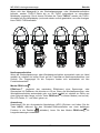
MD 9240 True RMS Power Clamp Meter Operation Notes on Displacement Power Factor & Total Power Factor Introduction: Power is the rate of change of energy with respect to time (in terms of voltage V and current A). Instantaneous (real) power w = vi where v is the instantaneous voltage and i the instantaneous current. The average (real) power is the mean of vi and is given by: W = ω/2π∫vi dt , over the interval from 0 to 2π/ω Displacement Power Factor (more traditional): Assuming V and A are pure sinusoidal waveforms without harmonics (as in most traditional cases), that is, v = V sinωt and i = I sin (ωt -θ), the expression can be simplified to: W = 1/2 x V x I x Cos θ where V and I are the peak values, θ is the displacement power factor angle, and Cosθ is the displacement power factor. Using RMS values, it is written as: W = Vrms x Arms x Cosθ Practically, in such cases without harmonics, θ is also called the phase-shift angle of the current A to the voltage V. An inductive circuit is said to have a lagging power factor since current A lags voltage V (phase-shift angle θ and thus Sinθ are both “+”), and a capacitive circuit is said to have a leading power factor since current A leads voltage V (phase-shift angle θ and thus Sinθ are both “-”). Total Power Factor (encountering harmonics): When encountering distorted waveforms with the presence of harmonics, however, the simplified power expression should not be used since substituting the above mentioned pure sinusoidal V and A functions cannot fulfill the actual conditions. Cosine of phase-shift angle (Cosθ), or the displacement power factor, is no longer the only component constituting the overall power factor. Harmonics do increase apparent power and thus decrease the overall power factor. That is, the Total Power Factor is actually affected by both phase-shift angle and harmonics, and is given by the expression: Total Power Factor (PF) = Real Power (W) / Apparent Power (VA) In order to improve overall system power factor, nowadays power-system engineer needs to address both phase-shift and harmonics problems. Practically, harmonics should be dealt with (e.g. filtering out) before phase-shift to be corrected (e.g. installing capacitors in parallel with inductive loads). Power function Set the slide-switch function-selector to the Power position. Default at last selected function. Press SELECT button momentarily selects between W (real power), VAR (reactive power) & VA (apparent power) measurement functions. PF (Total Power Factor) displays simultaneously in the secondary mini display. Denoting efficiency, absolute PF value is adopted. “A-lags” LCD annunciator turns on to indicate an inductive circuit, or Current A lags Voltage V (i.e., phase-shift angle θ is “+”). On the contrary, together with significant PF values, WITHOUT turning on “A-lags” indicates a capacitive circuit, or Current A leads Voltage V (i.e., phase-shift angle θ is “-”). 10