1
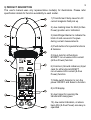
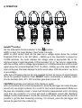
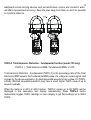
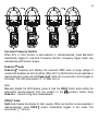
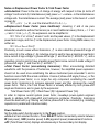
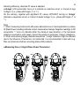
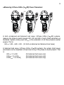
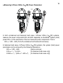
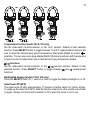
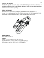
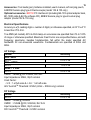
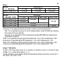
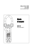
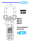
USER'S MANUAL
BM155
PowerClampTM Series
1
1) SAFETY
This manual contains information and warnings that must be followed for operating the
instrument safely and maintaining the instrument in a safe operating condition. If the
instrument is used in a manner not specified by the manufacturer, the protection
provided by the instrument may be impaired.
The meter meets the requirements for double insulation to IEC61010-2-032(2002),
EN61010-2-032(2002), UL61010B-2-032(2003):
Category III 600 Volts ac and dc.
PER IEC61010 OVERVOLTAGE INSTALLATION CATEGORY
OVERVOLTAGE CATEGORY II
Equipment of OVERVOLTAGE CATEGORY II is energy-consuming equipment to be
supplied from the fixed installation.
Note – Examples include household, office, and laboratory appliances.
OVERVOLTAGE CATEGORY III
Equipment of OVERVOLTAGE CATEGORY III is equipment in fixed installations.
Note – Examples include switches in the fixed installation and some equipment for
industrial use with permanent connection to the fixed installation.
OVERVOLTAGE CATEGORY IV
Equipment of OVERVOLTAGE CATEGORY IV is for use at the origin of the installation.
Note – Examples include electricity meters and primary over-current protection
equipment.
TERMS IN THIS MANUAL
WARNING identifies conditions and actions that could result in serious injury or even
death to the user.
CAUTION identifies conditions and actions that could cause damage or malfunction in
the instrument.
2
WARNING
To reduce the risk of fire or electric shock, do not expose this product to rain or moisture.
The meter is intended only for indoor use.
To avoid electrical shock hazard, observe the proper safety precautions when working
with voltages above 60 VDC or 30 VAC rms. These voltage levels pose a potential shock
hazard to the user.
Keep your hands/fingers behind the hand/finger barriers (of the meter and the test leads)
that indicate the limits of safe access of the hand-held part during measurement. Inspect
test leads, connectors, and probes for damaged insulation or exposed metal before
using the instrument. If any defects are found, replace them immediately.
This Clamp-on meter is designed to apply around or remove from uninsulated hazardous
live conductors. But still, individual protective equipment must be used if hazardous live
parts in the installation where measurement is to be carried out could be accessible.
CAUTION
Disconnect the test leads from the test points before changing meter functions.
INTERNATIONAL ELECTRICAL SYMBOLS
!
Caution ! Refer to the explanation in this Manual
Caution ! Risk of electric shock
Earth (Ground)
Double Insulation or Reinforced insulation
Fuse
AC--Alternating Current
DC--Direct Current
Application around and removal from hazardous live conductors is permitted
2) CENELEC Directives
The instruments conform to CENELEC Low-voltage directive 73/23/EEC and
Electromagnetic compatibility directive 89/336/EEC
3
3) PRODUCT DESCRIPTION
This user's manual uses only representative model(s) for illustrations. Please refer
specification details for function availability to each model.
1) Transformer Clamp Jaws for AC
current magnetic field pick up
2) Jaw marking lines for ACA (& thus
Power) position error indication
3) Hand/Finger Barrier to indicate the
limits of safe access to the jaws
during current measurements
4) Push-buttons for special functions
& features
5) Input Jack for all functions
EXCEPT non-invasive ACA current
(& thus Power) function
6) Common (Ground reference) Input
Jack for all functions EXCEPT
non-invasive ACA current (& thus
Power) function
7) Slide-switch Selector to turn the
power ON/OFF and Select a function
8) LCD display
9) Jaw trigger for opening the
transformer clamp jaws
10) Jaw center Indicators, at where
best ACA (& thus Power) accuracy is
specified
4) OPERATION
4
AutoVATM function
Set the slide-switch function-selector to the
position.
●With no input, the meter displays “Auto” when it is ready.
●With no ACA current input via the jaws but a voltage signal above the nominal
threshold of DC 2.4V or AC 30V (40Hz ~ 500Hz) up to the rated 600V is present on
V-COM terminals, the meter displays the voltage value in appropriate DC or AC,
whichever larger in peak magnitude. LCD annunciator “dc” or “ ” turns on respectively.
●On the contrary, with no voltage signal present on V-COM terminals but a ACA current
signal above the nominal threshold of AC 1A (40Hz ~ 500Hz) up to the rated 1000A is
input via the jaws, the meter displays the ACA current value. LCD annunciator “ ” turns
on accordingly.
●The Auto-VA feature stays at the auto-selected function as long as its signal remains
above the specified threshold. Press SELECT button momentarily to manually select
thru the functions ACA, ACV, DCV and then goes back to Auto-VA.
CAUTION (Application and removal of the Clamp-on meter)
●For non-invasive ACA current measurements, press the jaw trigger and clamp the jaws
around only one single conductor of a circuit for load current measurement. Make sure
the jaws are completely closed, or else it will introduce measurement errors. Enclosing
more than one conductor of a circuit will result in differential current (like identifying
leakage current) measurement. Locate the conductor(s) at the Jaws center as much as
possible to get the best measuring accuracy. For removal, press the jaw trigger and
remove the jaws from the conductor(s).
5
●Adjacent current-carrying devices such as transformers, motors and conductor wires
will affect measurement accuracy. Keep the jaws away from them as much as possible
to minimize influence.
THD%-F Total Harmonic Distortion - Fundamental function (model 155 only)
THD%-F = (Total Harmonics RMS / Fundamental RMS) x 100%
Total Harmonic Distortion - Fundamental (THD%-F) is the percentage ratio of the Total
Harmonics RMS value to the Fundamental RMS value of a voltage or current signal, and
is given by the above expression. An ideal sinusoidal waveform has a value of 0 THD%.
A badly distorted sinusoidal waveform may have a much higher THD% value of up to
several hundreds.
When the meter is in ACV or ACA function, THD%-F values up to 99 THD% will be
displayed in the secondary mini display automatically. Press THD%-F button
momentarily toggles THD% readings to main display to get full readings up to 999.9
THD%.
6
Line-level Frequency function
When ACV or ACA function is auto-selected or manual-selected, press Hz button
momentarily toggles to Line-level Frequency function. Frequency trigger levels vary
automatically with function ranges.
Peak-rms mode
Peak-rms compares and displays the maximum RMS value of surge voltage or
current with durations as short as 65ms. When ACV or ACA function is auto-selected or
manual-selected, press and hold Peak-rms button for one second or more toggles to
this mode. The LCD annunciators “P-” & “Max” turn on.
Note:
Manually disable the APO feature (press & hold the HOLD button while setting the
slide-switch function-selector from any position to the
position.) before using
Peak-rms mode for long-term measurements.
HOLD mode
Hold mode freezes the display for later viewing. When any function is auto-selected or
manual-selected, press HOLD button momentarily toggles to this mode. The
annunciator “ ” turns on.
7
Notes on Displacement Power Factor & Total Power Factor
●Introduction: Power is the rate of change of energy with respect to time (in terms of
voltage V and current A). Instantaneous (real) power w = vi where v is the instantaneous
voltage and i the instantaneous current. The average (real) power is the mean of vi and
is given by:
W = ω/2π∫vi dt , over the interval from 0 to 2π/ω
●Displacement Power Factor (more traditional): Assuming V and A are pure
sinusoidal waveforms without harmonics (as in most traditional cases), that is, v = V sin
ωt and i = I sin (ωt -θ), the expression can be simplified to:
W = 1/2 x V x I x Cosθ where V and I are the peak values, θ is the displacement
power factor angle, and Cosθ is the displacement power factor. Using RMS values, it is
written as:
W = Vrms x Arms x Cosθ
Practically, in such cases without harmonics, θ is also called the phase-shift angle of
the current A to the voltage V. An inductive circuit is said to have a lagging power factor
since current A lags voltage V (phase-shift angle θ and thus Sinθ are both “+”), and a
capacitive circuit is said to have a leading power factor since current A leads voltage V
(phase-shift angle θ and thus Sinθ are both “-”).
●Total Power Factor (encountering harmonics): When encountering distorted
waveforms with the presence of harmonics, however, the simplified power expression
should not be used since substituting the above mentioned pure sinusoidal V and A
functions cannot fulfill the actual conditions. Cosine of phase-shift angle (Cosθ), or the
displacement power factor, is no longer the only component constituting the overall
power factor. Harmonics do increase apparent power and thus decrease the overall
power factor. That is, the Total Power Factor is actually affected by both phase-shift
angle and harmonics, and is given by the expression:
Total Power Factor (PF) = Real Power (W) / Apparent Power (VA)
In order to improve overall system power factor, nowadays power-system engineer
needs to address both phase-shift and harmonics problems. Practically, harmonics
should be dealt with (e.g. filtering out) before phase-shift to be corrected (e.g. installing
capacitors in parallel with inductive loads).
Power function
Set the slide-switch function-selector to the Power position.
●Default at last selected function. Press SELECT button momentarily selects between
W (real power), VAR (reactive power) & VA (apparent power) measurement functions.
●PF (Total Power Factor) displays simultaneously in the secondary mini display.
8
Denoting efficiency, absolute PF value is adopted.
●“A-lags” LCD annunciator turns on to indicate an inductive circuit, or Current A lags
Voltage V (i.e., phase-shift angle θ is “+”).
On the contrary, together with significant PF values, WITHOUT turning on “A-lags”
indicates a capacitive circuit, or Current A leads Voltage V (i.e., phase-shift angle θ is
“-”).
Note:
1. When measuring load circuits with power absorptions as in most applications, positive
W (Real Power) readings indicate correct measurement setups. Negative readings (LCD
annunciator “-“ turns on) indicate either the clamp-on jaws direction or the test leads
polarity is reversed in such cases. Correct the setups to get proper “A-lags” indications.
2. When encountering largely distorted waveforms, “A-lags” detection might be affected
due to the influence of harmonics. As mentioned, it is recommended to deal with (e.g.
filter out) harmonics before correcting phase-shift problems.
●Measuring One or Single Phase Power Parameters:
9
●Measuring 3-Phase 4-Wire (3
4W) Power Parameters:
In both un-balanced and balanced load cases, 3-Phase 4-Wire (3 4W) systems,
measure the phase-to-neutral powers kW1, kW2 and kW3 of each phase separately as
illustrated. System (total) power kWTotal is the summation of all three phase-to-neutral
powers. That is:
kWTotal = kW1 + kW2 + kW3 (for both un-balanced and balanced load cases)
In balanced load cases, 3-Phase 4-Wire (3 4W) systems, the system (total) power
parameters can be simplified to three times of any of the phase-to-neutral powers. That
is:
kWTotal = 3 x kW1
(for balanced load cases only)
kVATotal = 3 x kVA1
(for balanced load cases only)
kVARTotal = 3 x kVAR1
(for balanced load cases only)
●Measuring 3-Phase 3-Wire (3
3W) Power Parameters:
10
In both un-balanced and balanced load cases, 3-Phase 3-Wire (3 3W) systems,
measure the power components kW1 and kW2 separately as illustrated. System (total)
power kWTotal is the summation of the two measured power components. That is:
kWTotal = kW1 + kW2 (for both un-balanced and balanced load cases)
In balanced load cases, 3-Phase 3-Wire (3 3W) systems, the system (total) power
parameters can be achieved by the following expressions:
kWTotal = kW1 + kW2
(same as above)
(for balanced load cases only)
kVATotal = √3 x kVA1
kVARTotal = √(kVATotal2 - kWTotal2) (for balanced load cases only)
11
Temperature function (model 152 & 155 only)
Set the slide-switch function-selector to the oC/oF position. Default at last selected
function. Press SELECT button to toggle between oC and oF measurement functions. Be
sure to insert the banana-plug type-K temperature bead probe Bkp60 at correct
polarities. You can also use a plug adapter Bkb32 (Optional purchase) with banana pins
to type-K socket to adapt other type-K standard mini plug temperature probes.
Ω/ functions
Set the slide-switch function-selector to the Ω/
function position. Default at last
selected function. Press SELECT button to toggle between Ω and
measurement
functions.
Backlighted display (models 152 & 155 only)
Press the SELECT button for 1 second or more to toggle the display backlight on or off.
Auto Power Off (APO)
The meter turns off after approximately 17 minutes of neither switch nor button activity.
To wake up the meter from APO, slide the function-selector to other positions and back
on again. Always turn the function-selector to OFF when the meter is not in use.
12
Disabling Auto-Power-Off (APO)
Press-and-hold the HOLD button while sliding the function-selector to a (designated)
function-selector position. This disables the Auto-Power-Off feature of the functions on
that particular function-selector position. The LCD displays “ ” & “ ” to confirm
activation right after the HOLD button is released. Slide the function-selector to any other
positions then resumes Auto-Power-Off feature.
RS232C PC computer interface capabilities
The instrument equips with an optical isolated data output port at the bottom case near
the battery compartment. Optional purchase PC interface kit BR15X (including BA-1XX
Optical Adapter Back, BC-100R Cable & Bs15x Software CD) is required to connect the
meter to PC computer thru RS232C protocol. The RS232C Data Recording System
software Bs15x equips with a digital meter, an analog meter, a comparator meter, and a
Data Graphical recorder. Refer to the README file comes with the interface kit for
further details.
Press-and-hold the Hz button while sliding the function-selector to a (designated)
function-selector position. This enables data output of the functions on that particular
function-selector position. The LCD displays “ ” to confirm activation right after the Hz
button is released. Slide the function-selector to any other positions then disables data
output.
5) MAINTENANCE
WARNING
To avoid electrical shock, disconnect the meter from any circuit, remove the test leads
from the input jacks and turn OFF the meter before opening the case. Do not operate
with open case.
Trouble Shooting
If the instrument fails to operate, check batteries and test leads etc., and replace as
necessary. Double check operating procedure as described in this user’s manual
If the instrument voltage-resistance input terminal has subjected to high voltage transient
(caused by lightning or switching surge to the system) by accident or abnormal
conditions of operation, the series fusible resistors will be blown off (become high
impedance) like fuses to protect the user and the instrument. Most measuring functions
through this terminal will then be open circuit. The series fusible resistors and the spark
gaps should then be replaced by qualified technician. Refer to the LIMITED WARRANTY
section for obtaining warranty or repairing service.
13
Cleaning and Storage
Periodically wipe the case with a damp cloth and mild detergent; do not use abrasives or
solvents. If the meter is not to be used for periods of longer than 60 days, remove the
batteries and store them separately
Battery replacement
The meter uses standard 1.5V AAA Size (NEDA 24A or IEC LR03) battery X 2
Loosen the 2 captive screws from the battery cover case. Lift the battery cover case.
Replace the batteries. Replace battery cover case. Re-fasten the screws.
6) Specifications
General Specifications
Display :
Voltage functions: 6000 counts LCD display(s)
Power, Ohm & Hz functions: 9999 counts LCD display(s)
ACA clamp-on function: 4000 counts LCD display(s)
14
Update Rate :
Power function: 1 per second nominal
Voltage, ACA clamp-on, Ohm, Hz & Temperature functions: 4 per second nominal
Polarity : Automatic
Low Battery : Below approx. 2.4V
Operating Temperature : 0oC to 40oC
Relative Humidity : Maximum relative humidity 80% for temperature up to 31oC
decreasing linearly to 50% relative humidity at 40oC
Altitude : Operating below 2000m
Storage Temperature : -20oC to 60oC, < 80% R.H. (with battery removed)
Temperature Coefficient : nominal 0.15 x (specified accuracy)/ oC @(0oC -18oC or
28oC -40oC), or otherwise specified
Sensing : True RMS sensing for all models
Safety : Meets IEC61010-2-032 (1994), EN61010-2-032(1995), UL3111-2-032(1999).
Measurement Category : III 600 Volts ac & dc
Transient protection : 6.5kV (1.2/50μs surge) for all models
Pollution degree : 2
E.M.C. : Meets EN61326(1997, 1998/A1), EN61000-4-2(1995), and EN61000-4-3(1996)
In an RF field of 3V/m:
Total Accuracy = Specified Accuracy + 45 digits
Performance above 3V/m is not specified
Overload Protections :
ACA Clamp-on jaws : AC 1000A rms continuous
+ & COM terminals (all functions) : 600VDC/VAC rms
Power Supply : standard 1.5V AAA Size (NEDA 24A or IEC LR03) battery X 2
Power Consumption :
Voltage, ACA, Hz & Power functions: 10mA typical
Ohm & Temperature functions: 4mA typical
APO Timing : Idle for 17 minutes
APO Consumption : 10μA typical
Dimension : L224mm X W78mm X H40mm
Weight : 224 gm approx
Jaw opening & Conductor diameter : 45mm max
Special features : Backlight display (model 152 & 155 only); AutoVATM (Auto Selection
on ACV, DCV or ACA functions); Power measurement of selectable W, VAR & VA with
dual-display Total Power Factor features; Total harmonic distortion THD%-F (model 155
only); PEAK-rms HOLD
15
Accessories : Test leads (pair), batteries installed, user's manual, soft carrying pouch,
& BKP60 banana plug type-K thermocouple (model 152 & 155 only)
Optional accessories : BR15X PC interface kit (including BA-1XX optical adapter back,
BC-100R cable & Bs15x software CD), BKB32 banana plug to type-K socket plug
adaptor (model 152 & 155 only)
Electrical Specifications
Accuracy is ±(% reading digits + number of digits) or otherwise specified, at 23 oC ±5 oC
& less than 75% R.H.
True RMS (all models) ACV & ACA clamp-on accuracies are specified from 0% to 100%
of range or otherwise specified. Maximum Crest Factor are as specified below, and with
frequency spectrums, besides fundamentals, fall within the meter specified AC
bandwidth for non-sinusoidal waveforms. Fundamentals are specified at 50Hz and
60Hz.
AC Voltage
RANGE
Accuracy
50Hz / 60Hz
600.0V
0.5% + 5d
45Hz ~ 500Hz
600.0V
1.5% + 5d
500Hz ~ 3.1kHz
600.0V
2.5% + 5d
CMRR : >60dB @ DC to 60Hz, Rs=1kΩ
Input Impedance: 2MΩ, 30pF nominal
Crest Factor:
< 2.3 : 1 at full scale & < 4.6 : 1 at half scale
ACV AutoVATM Threshold: 30VAC (40Hz ~ 500Hz only) nominal
DC Voltage
RANGE
600.0V
NMRR : >50dB @ 50/60Hz
CMRR : >120dB @ DC, 50/60Hz, Rs=1kΩ
Input Impedance: 2MΩ, 30pF nominal
DCV AutoVATM Threshold: 2.4VDC nominal
Accuracy
0.5% + 5d
16
PEAK-rms HOLD (ACA & ACV only)
Response: 65ms to 90%
Ohms
RANGE
999.9Ω
Open Circuit Voltage : 0.4VDC typical
Accuracy
1.0% + 6d
Audible Continuity Tester
Audible threshold: between 10Ω and 300Ω.
Response time: 250μs
ACA Current (Clamp-on)
RANGE
Accuracy 1) 2)
50Hz / 60Hz
40.00A, 400.0A, 1000A
1.0% + 5d
45Hz ~500Hz
40.00A, 400.0A
2.0% + 5d
1000A
2.5% + 5d
500Hz ~ 3.1kHz
40.00A, 400.0A
2.5% + 5d
1000A
3.0% + 5d
ACA AutoVATM Threshold: 1A AC (40Hz ~ 500Hz only) nominal
Crest Factor:
< 2.5 : 1 at full scale & < 5.0 : 1 at half scale for 40.00A & 400.0A ranges
< 1.4 : 1 at full scale & < 2.8 : 1 at half scale for 1000A range
1)Induced error from adjacent current-carrying conductor: < 0.06A/A
2)Specified accuracy is from 1% to 100% of range and for measurements made at the jaw
center. When the conductor is not positioned at the jaw center, position errors introduced
are:
Add 1% to specified accuracy for measurements made WITHIN jaw marking lines
(away from jaw opening)
Add 4% to specified accuracy for measurements made BEYOND jaw marking lines
(toward jaws opening)
Temperature (model 152 & 155 only)
RANGE
Accuracy
-50oC ~ 300oC
2.0% + 3oC
-58oF ~ 572oF
2.0% + 6oF
Type-K thermocouple range & accuracy not included
Add 3oC (or 6oF) to specified accuracy @ -20oC ~ -50oC (or @ -4oF ~ -58oF)
Frequency
RANGE
5.00Hz ~ 500.0Hz
Sensitivity (Sine RMS)
40A range: > 4A
400A range: > 40A
1000A range: > 400A
600V range: > 30V
THD%-F 1) (model 155 only)
RANGE
0.0% ~999.9% 2)
Accuracy
0.5%+4d
Harmonic order
Fundamental
2nd ~ 3rd
4th ~ 16th
17th ~ 46th
47th ~ 51st
Accuracy 3)
1.5% of Reading + 6d
5.0% of Reading + 6d
2.5% of Reading + 6d
3.0% of Reading + 6d
4.5% of Reading + 6d
1)THD-F
is defined as:
(Total Harmonic RMS / Fundamental RMS) x 100%
2)Range for Dual Display mode: 0% ~ 99%
3)Specified accuracy @ ACA fundamental > 5A ; ACV fundamental > 50V
Total Power Factor (PF)
RANGE
0.10 ~ 0.99
Accuracy 1)
F ~ 21st
22nd ~ 51st
3d
5d
1)Specified accuracy @ ACA fundamental > 2A ; ACV fundamental > 50V
17
Power
RANGE
0 ~ 600.0kVA
@ PF = 0.99 ~ 0.1
18
F ~ 10th
2.0%+6d
Accuracy 1) 2)
11th ~ 46th
3.5%+6d
47th ~ 51st
5.5%+6d
RANGE
Accuracy 1) 3)
0 ~ 600.0kW / kVAR
F ~ 10th
11th ~ 25th
26th ~ 46th
47th ~ 51st
@ PF = 0.99 ~ 0.70
2.0%+6d
3.5%+6d
4.5%+6d
10%+6d
@ PF = 0.70 ~ 0.50
3.0%+6d
@ PF = 0.50 ~ 0.30
4.5%+6d
@ PF = 0.30 ~ 0.20
10%+6d
15%+6d
1)Specified accuracy is for ACA clamp measurement at the center of jaws. When the
conductor is not positioned at the jaw center, position errors introduced are:
Add 1% to specified accuracy for ACA measurements made WITHIN jaw marking
lines (away from jaw opening)
Accuracy is not specified for ACA measurement made BEYOND jaw marking lines
(toward jaws opening)
2)Add 1% to specified accuracy @ ACA fundamental < 5A or ACV fundamental < 90V.
Accuracy is not specified @ ACA fundamental < 1A or ACV fundamental < 30V
3)Add 1% to specified accuracy @ ACA fundamental < 5A or ACV fundamental < 90V.
Accuracy is not specified @ ACA fundamental < 2A or ACV fundamental < 50V
A-lags 1) Indication:
“A-lags” LCD annunciator turns on to indicate an inductive circuit, or Current A lags
Voltage V (i.e., phase-shift angleθ is “+”).
1)A-lags Indication is specified at 50/60Hz fundamental without harmonics, and at ACV >
90V, ACA > 9A, & PF < 0.95
LIMITED WARRANTY
BRYMEN warrants to the original product purchaser that each product it manufactures
will be free from defects in material and workmanship under normal use and service
within a period of one year from the date of purchase. BRYMEN's warranty does not
apply to accessories, fuses, fusible resistors, spark gaps, batteries or any product which,
in BRYMEN's opinion, has been misused, altered, neglected, or damaged by accident or
abnormal conditions of operation or handling.
To obtain warranty service, contact your nearest BRYMEN authorized agent or send the
product, with proof of purchase and description of the difficulty, postage and insurance
prepaid, to BRYMEN TECHNOLOGY CORPORATION. BRYMEN assumes no risk for
damage in transit. BRYMEN will, at its option, repair or replace the defective product free
of charge. However, if BRYMEN determines that the failure was caused by misused,
altered, neglected, or damaged by accident or abnormal conditions of operation or
handling, you will be billed for the repair.
THIS WARRANTY IS EXCLUSIVE AND IS IN LIEU OF ALL OTHER WARRANTIES,
EXPRESSED OR IMPLIED, INCLUDING BUT NOT LIMITED TO ANY IMPLIED
WARRANTY OR MERCHANTABILITY OR FITNESS FOR A PARTICULAR PURPOSE
OR USE. BRYMEN WILL NOT BE LIABLE FOR ANY SPECIAL, INDIRECT,
INCIDENTAL OR CONSEQUENTIAL DAMAGES.
ELBRO LTD • Gewerbestrasse 4 • P.O. Box 11 • CH-8162 Steinmaur •
Phone +41 (0)44 854 73 00
Fax +41 (0)44 854 73 01 • e-mail: [email protected] • www.elbro.com
P/N:7M1C-0591-A000