1
WAGNER Project Pro 119 - 0418C
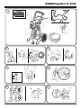
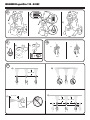
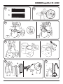
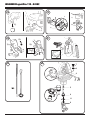
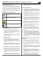
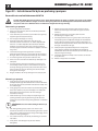
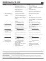
Figure 23 - Pump section replacement instructions
Kit Part Number 0418716
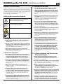
Danger
Always wear protective eye wear while servicing the pump. Be sure to follow the Pressure Relief Procedure when shutting
the unit down for any purpose, including servicing or adjusting. After performing the Pressure Relief Procedure, be sure to
unplug the unit before servicing or adjusting. Area must be free of solvents and paint fumes.
Disassembly of the Pump Section
adjustable wrench. This will drive the bottom seal into the
correct position.
10.Turn pump right side up and apply a few drops of Separating
Oil or light household oil between the top nut (7) and piston
(5). This will prolong the seal life.
11. Install front cover and three (3) screws.
12. Install the suction set.
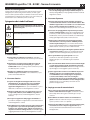
1. Remove the suction set.
2. Remove the front cover and the three screws that secure it
using a T20 Torx head driver.
3. Remove the yoke screw (1) and washer (2) that secures the
dowel pin (3). The dowel pin connects the yoke (4) to the
piston (5).
4. Using a pliers, pull the dowel pin out.
5. Inspect the yoke assembly and piston. In order to remove all
the necessary parts, the piston must not be in the bottom
dead center position. If the piston is at the bottom of the
stroke, install the front cover and screws, turn the pump on
briefly to index the piston, unplug the unit, and repeat step 2.
6. Loosen the screw connection of the inlet valve and remove
the solenoids (Figure 19 a). Make sure that the O-ring does not
get lost. Unscrew the inlet valve unit (6) from the basic unit.
7. Remove the piston assembly by pushing down on the piston
near the yoke.
8. Unscrew and remove the top nut (7) using and adjustable
wrench.
9. Remove the worn seals using a flat head screwdriver or punch.
Remove the top seal (8) from the top and the bottom seal (9)
from the bottom by pressing against the side of the seal and
popping it out. Be sure not to scratch the housing where the
seals are located.
10. Clean the area where the new seals are to be installed.
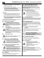
Warning!
Danger
The wires in this mains lead are coloured in accordance with the
following code:
green/yellow = earth
blue = neutral brown = live
As the colours of the wires in the mains lead of this appliance may not
correspond with the coloured markings identifiying the terminals in
your plug, proceed as follows:
The wire which is coloured green and yellow must be connected to
the terminal in the plug which is marked with the letter E or by the
earth symbol or coloured green or green and yellow.
The wire which is coloured blue must be connected to the terminal
which is marked with the letter N or coloured black.
The wire which is coloured brown must be connected to the
terminal which is marked with the letter L or coloured brown.
Should the moulded plug have to be replaced, never re-use the
defective plug or attempt to plug it into a different 13 A socket. This
could result in an electric shock.
Should it be necessary to exchange the fuse in the plug only use
fuses approved by ASTA in accordance with BS 1362. Only 13 Amp
fuses may be used.
To ensure that the fuse and fuse carrier are correctly mounted
please observe the provided markings or colour coding in the plug.
After changing the fuse, always make sure that the fuse carrier is
correctly inserted. With out the fuse carrier, it is not permissible to
use the plug.
The correct fuses and fuse carriers are available from your local
electrical supplies stockist.
•
•
•
•
Assembly of the Pump Section
1. Lubricate the new top seal (8) with Separating Oil or light
household oil and by hand place the seal (cup side of seal
down) into the top port of the housing.
2. Place a small amount of bearing grease on the threads of the
top nut (7). Place the top nut into the top of the housing and
tighten with an adjustable wrench. This will drive the top seal
into the correct position.
3. Turn the pump upside down. Lubricate the seal on the piston/
seal assembly (5, 9) similar to the top seal. Place the piston/
seal assembly into the bottom of the housing.
i
If the supply cord of this appliance is damaged, it
must only be replaced by a repair shop appointed
by the manufacturer, because special purpose tools
are required.
•
•
•
•
DO NOT attempt to remove the bottom seals from the
new piston.
4. Insert the insertion tool (10) and thread into position to
properly seat the piston/seal. Thread fully until tight. Remove
the insertion tool.
5. Align the piston (5) with the yoke (4). Be careful not to
damage the piston.
6. Apply a bearing grease to the holes in the yoke where the
dowel (3) is inserted.
7. Install the dowel pin (3) to connect the yoke to the piston. The
piston may have to be moved up or down to do this.
8. Install the yoke screw (1) and washer (2) to secure the dowel
pin.
9. Install the new O-ring (11) on the inlet valve assembly,
lubricate with Separating Oil or light household oil, thread
into the bottom (inlet) of the housing, and tighten with an
20