1
G
B
EMERGENCY RELEASE
Carry out only after power supply to the motor has been interrupted!
In the event of a power supply failure, release the gearmotor, so that you
can move the boom by hand.
To do so, use the RIB key supplied and turn it in the clockwise sense,
until the stop is reached (Pic. 6).
By doing so, the barrier boom works independent from the gearmotor and
it can be moved by hand.
When power is supplied again, turn the key counterclockwise strongly
until you block it.
MAINTENANCE
To be undertaken only by specialized staff after disconnecting
power supply.
After every 100.000 cycles check:
- boom balance (see the paragraph “ADJUSTING THE BALANCING
SPRINGS”);
- the tightness of the release knob (see the paragraph “EMERGENCY
RELEASE”);
- the tightness of the boom holding attachment and the implantation of
the boom (see the paragraph “ASSEMBLING THE BOOM”);
- the wear on the mechanical stops and the limiti switch setting (see the
paragraph “LIMIT SWITCH SETTING”).
6
-G
rease the bearings of the boom carrier shaft and the threaded spring
guide bar.
The described maintenance is vital for the corrected operation of
the product in the time.
PARK code BC07062
PARK CRX code BC07063
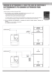
ELECTRIC CONNECTIONS
POINT A - control panel features
J1
L-N
Main power supply 230Vac 50/60Hz upon request)
J2
COM
LSC
LSO
LSSC
LSSO
TLC
Common contact
Closing limit switch contact (NC)
Opening limit switch contact (NC)
Closing slowing down limit switch contact (NO)
Opening slowing down limit switch contact (NO)
Vehicle presence signal (NO) (only when switched to PARK
mode)
Photocells contact (NC)
Safety strip contact (NC)
Common contact
Safety strip self-test power supply +12Vdc 500mA max
Accessories power supply +12Vdc 500mA max
Accessories power supply -12Vdc 500mA max
J4
PHOT. NC
EDGE NC
COM
D+ TEST
D+
D-
J8
J1
AERIAL
U - MOTOR
V-W - MOTOR
Blinker (max 40W)
Motor common connection
Motor inverters and condenser connection
J5
OK CLOSE
OPEN 1
CLOSE
STOP
K BUTT.
COM
Immediate closure command contact (only when switched to PARK mode)
Open1 button contact (NO)
Close button contact (NO)
Stop button contact (NC)
Single pulse button (NO)
Common contact (common line for all the commands and safety inputs)
J6
PROBE
Heating probe connection terminal block (code ACG4666
optional)
J7
RADIO
Built in radio module (only CRX) or connector for radio receiver
RIB, 12Vdc supply
J8
AUX. ATT.
Card 1 relay connector (code ACQ9080) for management of
courtesy light or boom arm locking magnet
Card 3 relay connector (code ACQ9081) for management of
courtesy light or boom arm locking magnet and traffic lights.
J9
SW PARK
DO NOT TOUCH THE JUMPER!
IF REMOVED THE OPERATOR DOES NOT FUNCTION!
J10
SW RADIO
DO NOT TOUCH THE JUMPER!
IF REMOVED THE RADIO SYSTEM DOES NOT FUNCTION!
S3
PROG.
Programming button
TRIMMER LOW
SPEED
Slow closure speed electronic regulator
J4
S3
TR2
J9
J7
J6
J5
J3
J10
OPEN 2
SIGNAL
Barrier opening button 2 contact (NO) (only when switched to PARK mode)
Barrier open signal 12Vdc
Buzzer - Acoustic signal connection (12Vdc max 200 mA)
Radio antenna
J3
TR2