1
5.3 Cutting depth adjustment
The cutting depth is continuously variable between 0
and 57, graduated in 1mm steps.
Proceed as follows:
•
•
•
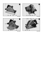
Adjust the indicator 10 (Fig. 4) by turning it into
the top or bottom position, depending on
whether you are working with or without the
guide rail.
Set the cutting depth with the depth stop 11
according to the scale. The limit stop has a 1
mm latching mechanism.
In order to set intermediate measurements, you
can turn the cylinder screw 12 (Fig. 4) with the
Allen key 4 (retaining bracket Fig. 2). One turn
corresponds to 1 mm change in cutting depth.
5.5 Plunge cuts
Danger
Risk of backlash during plunge
cuts! Prior to plunging, place the
machine with the rear edge of its
base plate against a limit stop
fastened on the workpiece. When
using the guide rail (special
accessories) you must fasten the
limit stop available as special
accessory on the guide rail. Keep
a firm hold on the machine handle
during plunging and push the saw
lightly forward!
•
Always set the cutting depth
approx. 2 to 5 mm larger than the
material thickness to be cut.
5.4 Setting for bevel cuts
For bevel cuts, the saw unit can be set to any angle
between 0 °and 45°.
•
•
•
Unfasten the wing screw 13 (Fig. 4).
Adjust the angle according to the scale on the
segment for tilting.
Afterwards, tighten the wing screw 13.
•
•
•
•
•
5.6 Sawing according to tracings
The figure is equipped with a tracked score indicator
17 (Fig. 1) both for straight cuts and for bevel cuts.
This tracing edge corresponds to the saw blade's
inside.
•
•
In addition, the machine can be tilted to -1° or 48°.
To tilt to -1°, pull the slide bar 14 (Fig. 4)
backwards in the direction of the arrow and hold
on to it.
Tilt the machine to -1°.
To tilt the machine to 48°, press the limit stop 15
(Fig. 3) downwards.
Tilt the machine to 48°.
45° and 0°- limit stop are automatically reset
after they have been traversed.
-21-
The markings 16 (Fig. 1) on the bottom saw
guard and on the slide bar serve as orientation
for the cutting area of the completely plunged
saw blade if the guide rail (special accessories)
is used.
•
•
Secure the workpiece against shifting and
arrange the workpiece supports such that the
saw blade is running freely underneath the
workpiece.
Hold the machine by its handle and place the
front part of its base plate onto the workpiece.
Switch on the plunge cut saw (see Chapter 5.2).
Plunge to the set cutting depth and slide the
machine evenly forward in the direction of the
cut.
When the cut is completed, switch off the saw
by releasing the gearshift lever 8 (Fig. 4). Tilt the
saw unit back into the top locked position.
5.7 Sawing with parallel guide fence
When making parallel cuts, the parallel guide fence
18 (Fig. 1) serves to saw parallel to an already
existing edge. The guide fence can be attached to the
left or right of the machine. The cutting range on the
right-hand side amounts to approx. 140 mm and on
the left-hand side to approx. 295 mm.