1
ENGLISH
5.
Special Product Features
– 45q cutting angle range for bevel
cuts, sawhead tilted to the left.
– 94 q cutting angle range for mitre
cuts (47 q left through 47 q right)
with nine preset stops.
– Integrated cutting depth limiter for
grooving.
– Precise and sturdy die-cast aluminium construction.
– TCT saw blade.
– Unproblematic saw blade change
by saw blade lock; no dismounting
of the retractable blade guard required.
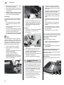
58
59
60
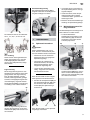
Bevel tilt setting
After the lock lever (61) at the rear has
been loosened the saw can be tilted
continously from 0° (vertical) through
45° to the left of vertical.
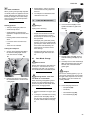
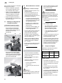
62
63
The rotating table engages in positive
stops at 0°, 15°, 22.5°, 30° and 45° positions.
– Sliding facility (track arm) for sawing
wider workpieces.
– Table extension with stock stop to
cut longer workpieces safely.
– Work clamp to hold workpieces securely.
– Chip bag for simple and effective
collection of chips.
– Laser guide for exact alignment of
markings with the cutting line.
61
Caution
To ensure that the mitre angle does not
change during cutting tighten the lock
screw (63) of the rotating table (also in
the preset positions!).
– Cutting area illumination.
6.
A
Machine Details
ON/OFF switch for motor (58)
Push/pull action
To turn the motor ON:
The track arm permits the cutting of
workpieces having a larger cross section. The push/pull action can be used
for all types of cuts (standard cross
cuts, mitre cuts, bevel cuts and compound mitre cuts as well as grooves).
x Press and hold the ON/OFF switch.
To turn the motor OFF:
x Release the ON/OFF switch.
ON/OFF switch for cutting area
illumination (59)
Switch the lighting for the cutting area
on and off.
ON/OFF switch for laser guide (60)
A
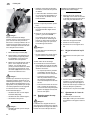
Caution!
To keep the bevel angle from changing
while sawing, the locking lever of the
track arm holder must be tightened.
The following illustration shows the
track arm in the forward position.
64
Switch the laser guide on and off.
Rotating table
For mitre cuts the rotating table can, after the lock screw (63) and the table
lock lever (62) have been loosened, be
rotated 47° to the left or 47° to the right.
This way the cutting angle is changed
against the guide edge of the work
piece.
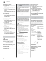
When the track arm is not needed secure it in the rear position with the lock
screw (64).
23