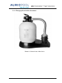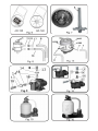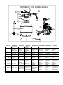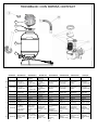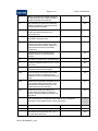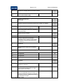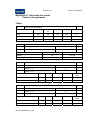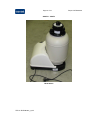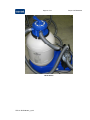
1
Address: Passeig Sanllehy, 25 E-08213 Polinyà (Spain) Phone. + 34 937 131 855 - Fax. + 34 937 134 111 PRODUCT VERIFICATION FILE PRODUCT: Monoblock filters AR135 and variations REFERENCE: Various DATE: April 2009 MANUFACTURER: METALAST S.A.U. Passeig Sanllehy 25 08213 POLINYA BARCELONA SPAIN AR 135 CE FILE V1 1 out of 13 Address: Passeig Sanllehy, 25 E-08213 Polinyà (Spain) Phone. + 34 937 131 855 - Fax. + 34 937 134 111 CONTENT INDEX 1.- General data ...............................................................................................................4 1.1.- Manufacturer......................................................................................................4 1.2.- Product identification.........................................................................................4 1.3.- Product description ............................................................................................4 1.4.- Product function.................................................................................................5 1.5.- Product active elements .....................................................................................6 1.6.- Accessories ........................................................................................................6 2.- Technical specifications and solution description .....................................................6 2.1.- Product function limits.......................................................................................6 2.2.- Risk identification..............................................................................................6 2.3.- Risk analysis ......................................................................................................6 2.4.- Risk reduction actions done ...............................................................................7 2.5.- Protection against risks ......................................................................................7 2.6.- Information and warnings ..................................................................................7 2.7.- Information and warnings labels........................................................................7 2.8.- Additional protective actions .............................................................................8 2.9.- Harmonized standards to be applied ..................................................................8 2.10.- Product analysis according to low tension directive........................................8 2.11.- Product analysis according to EMC directive..................................................8 3.- Instruction manuals....................................................................................................9 3.1.- User instruction manual .....................................................................................9 3.2.- Maintenance instruction manual ........................................................................9 3.3.- Product parts list ................................................................................................9 3.4.- Spare parts’ list ..................................................................................................9 4.- EC-Conformity declaration .......................................................................................9 5.- Annex.........................................................................................................................9 5.1.- Parts’ declarations (RoHS, EC, …) ...................................................................9 5.2.- Parts’ drawings...................................................................................................9 5.3.- Electrical installation scheme ............................................................................9 5.4.- Other tests. Calculations ..................................................................................10 AR 135 CE FILE V1 2 out of 13 Address: Passeig Sanllehy, 25 E-08213 Polinyà (Spain) Phone. + 34 937 131 855 - Fax. + 34 937 134 111 5.5.- Quality system to assure the production conformity .......................................10 5.6.- Photographs and other documents ...................................................................12 5.7.- Contact support phone numbers for customers................................................13 6.- Changes to the previous versions of the files ..........................................................13 6.1- Version 1 (April 2009)......................................................................................13 AR 135 CE FILE V1 3 out of 13 Address: Passeig Sanllehy, 25 E-08213 Polinyà (Spain) Phone. + 34 937 131 855 - Fax. + 34 937 134 111 1.- General data 1.1.- Manufacturer MANUFACTURER DATA NAME METALAST, S.A.U. IDENTIFICATION NUMBER A08246274 ADDRESS Passeig Sanllehy, 25 E-08213 Polinyà PHONE NUMBER: +34 93 713 18 55 1.2.- Product identification PRODUCT CHARACTERISTICS BRAND: GRE MODEL: AR135, AR135L, AR135E and AR 1350 REFERENCE: PRODUCTION START DATE: The identification labels for each model are attached to the present document As all the AR135 models and the 1350 have the same filtration unit, the label used is the same, even if the product flow rate and filtration speed is different, due to the hydraulic loses caused by all the accessories provided with the AR135 versions The AR135 versions (-L, -E) have also the same filtration unit, but have different skimmer, to be used with another model of pool. 1.3.- Product description The product is an assembly of a sand filter and an electrical self-priming pump. The assembly has a sand filter, a pump and a selecting valve. It could also include some accessories such as the connecting hoses. They are detailed in the product parts list. (Section 3.3) The pump assembled on this product is named “Compact” with reference 25470 and it is manufactured by Metalast S.A.U. AR 135 CE FILE V1 4 out of 13 Address: Passeig Sanllehy, 25 E-08213 Polinyà (Spain) Phone. + 34 937 131 855 - Fax. + 34 937 134 111 The product rated power and the filtration flow rate are detailed below. All the devices have been designed to be used in a 230V, 50 Hz electrical network. It is designed as a Class I household electrical device. The pump has an insulation degree class F and a service class S1. The device is provided with the cable and the plug, ready to be connected to the electrical network. The cable has been designed to be a class Y according to the EN 60335-1 standard, so it cannot be changed or repaired by the end user. PRODUCT DESCRIPTION MODEL RATED POWER FILTER DIAMETER FILTER FLOW RATE AR135 / AR1350 482 W 380 mm 5.5 m3/h 6 m3/h FILTRATION SAND WEIGHT CAPACITY 48.5 m3/m2.h 40 Kg PUMP USED MODEL PUMP USED PUMP MANUFACTURER CERTIFICATIONS SUBMITTED All listed COMPACT (25470) Metalast S.A.U. GS certificate Z1A 07 02 42435 010 The silica sand to be used should have an approximate grain size of 0.4 to 0.8 mm. With the recommended sand weight, the filter has to be filled at about 2/3 of its height. The AR1350 model has the same filter and pumping system than the AR135, but does not include some of the accessories, such as the skimmers or the silica sand. 1.4.- Product function The product has been designed to filter the water of a swimming pool by passing it through silica sand. It can also be used for pool bottom vacuum cleaners, according to the instruction manual. Another use described in the instruction manual is to drain the pool at the end of the season. The filter cannot be used for more than 4 hours without stopping for, at least, 2 hours. AR 135 CE FILE V1 5 out of 13 Address: Passeig Sanllehy, 25 E-08213 Polinyà (Spain) Phone. + 34 937 131 855 - Fax. + 34 937 134 111 1.5.- Product active elements The active electrical elements of the device are only the electrical motor of the pump. However, the whole assembly should be taken into account when the EN60335-2-41 standard is applied. 1.6.- Accessories The parts and accessories provided with the product are described in the parts list section (section 3.3) 2.- Technical specifications and solution description 2.1.- Product function limits The product has been designed to filter the water in a swimming pool. The water to be treated must be clean, with the usual levels of treating products such as bromine, chlorine, ozone or other commonly used in the pool treatment. It has not been designed to treat sea water. It is not suitable to be used as a filter for drinkable or irrigation water. It is advised in the instruction manual that the device must not be on while the pool is being used. The device is to be used with water in a temperature below 35ºC. 2.2.- Risk identification During the operation of the device, it can be dangerous for the persons or goods which are nearby the device or the pool installation. The risks have been analyzed according to the EN 60335-2-41 standard. Attached to the present document are the product certificate against the low-voltage directive, the testing report for the winding temperature and the protection degree test evidence for the whole assembly. 2.3.- Risk analysis The risks have been analyzed according to the EN 60335-2-41 standard. There are some different kinds of risks, such as: • Electrical risks • Risks to the device AR 135 CE FILE V1 6 out of 13 Address: Passeig Sanllehy, 25 E-08213 Polinyà (Spain) Phone. + 34 937 131 855 - Fax. + 34 937 134 111 • Risks to other objects 2.4.- Risk reduction actions done The actions to reduce the risk have been of different kinds: Design: The device has been designed and tested according to the EN 60335-2-41, the 89/392/EC (Directive of machines) and other standards. • Instruction manual: General information to the user for the installation and the use. The instruction manual is attached to the present document • Labels: Some specific information and warnings are detailed in some labels which are placed over the product. All the labels placed on the product are attached to the present document 2.5.- Protection against risks The user must follow all the instructions and take care of all the warnings contained in the instruction manual, warning labels and other informations that the manufacturer could include over the product or in the package. The user cannot perform any maintenance or reparation to the device. Any action involving opening the covers or dismantling parts which are not specifically advised in the instruction manual must be done by a technical service. This warning is included in the instructions manual. It is also specially advised in the instruction manual that the device cannot be touched with wet hands or any wet part of the body. 2.6.- Information and warnings All the information to reduce the risks to the persons or goods is included in the instruction manual and/or in the labels on the device. Any action which is not described in the instruction manual as to be performed by the final user must be done by an authorized technical service. 2.7.- Information and warnings labels The labels placed over the product are attached to the present document. AR 135 CE FILE V1 7 out of 13 Address: Passeig Sanllehy, 25 E-08213 Polinyà (Spain) Phone. + 34 937 131 855 - Fax. + 34 937 134 111 2.8.- Additional protective actions During the assembly or the use of the device there’s no need of special clothing or protecting devices, apart of the actions described in the instruction manual. 2.9.- Harmonized standards to be applied The harmonized standards involved in the device are: • Directive 2006/42/EC (General requirements for machine design) • Directive 2006/95/CE (Low voltage devices) • Directive 2004/108/CE (EMC) • Directive 2000/14/CE (Noise emission) • EN 61000-6-1 and -3 (Electro magnetic compatibility) • EN 60335-1 (Electrical household equipment), with its amendments and erratum • EN 60335-2-41 (Particular requirements for pumps) and amendments Other standards may apply depending on local regulations. 2.10.- Product analysis according to low tension directive The electrical active parts of the device have been tested according to the EN 60335-2-41 standard by TÜV Product service, in order to obtain the GS-certification. The certificate obtained is attached as an annex. No other electrical active part is used in the device. 2.11.- Product analysis according to EMC directive There’s only one active electrical part on the device, which is the electrical motor. The motor used in this equipment is an induction motor. As the induction motors are considered as “Inherently benign equipment”, the equipment is not affected by the EMC directive. (Chapter 1, article 1, point 3, directive 2004/108/EC). In the same way, the Gs-Certificate for the pump is attached to the present document. AR 135 CE FILE V1 8 out of 13 Address: Passeig Sanllehy, 25 E-08213 Polinyà (Spain) Phone. + 34 937 131 855 - Fax. + 34 937 134 111 3.- Instruction manuals 3.1.- User instruction manual The instruction manual is attached as an Annex to the present document. The instruction manual also includes the instructions for the function and the installation for other similar models. 3.2.- Maintenance instruction manual No specific maintenance manual is included in the device. The maintenance has to be done by a technical service. 3.3.- Product parts list The product parts list is listed in the instruction manual 3.4.- Spare parts’ list The spare parts are listed in the instruction manual 4.- EC-Conformity declaration The EC-Conformity declaration is included in the instructions manual 5.- Annex 5.1.- Parts’ declarations (RoHS, EC, …) Attached to the present document it can be found the GS-certificate for the pump. No other certificates or part’ 5.2.- Parts’ drawings The parts drawings are attached to the present document 5.3.- Electrical installation scheme No electrical installation scheme is included, as the device must be easily connected to the electrical network. The protections to be included to the specific network are detailed in the instruction manual. AR 135 CE FILE V1 9 out of 13 Address: Passeig Sanllehy, 25 E-08213 Polinyà (Spain) Phone. + 34 937 131 855 - Fax. + 34 937 134 111 5.4.- Other tests. Calculations According to the EN 60335-2-41 standard, section 6.2, the protection degree for a non-mobile pump situated in a swimming pool and over 3,5 m from the water must be, at least, X4. The pump protection degree overpasses this specification as it is certified as IP X5 As the pump is working in the same condition as it has been tested against EN 60335-2-41 standard, no other tests have been performed to it referring to heating or parts’ stability. 5.5.- Quality system to assure the production conformity The product manufacturing control procedures will be the same as used in the company, according to the implemented ISO 9001:2004 quality assurance system. In case of any complain from the final vendor, it will be treated according to the normal procedure. The company’s certificate is shown below. AR 135 CE FILE V1 10 out of 13 Address: Passeig Sanllehy, 25 E-08213 Polinyà (Spain) Phone. + 34 937 131 855 - Fax. + 34 937 134 111 AR 135 CE FILE V1 11 out of 13 Address: Passeig Sanllehy, 25 E-08213 Polinyà (Spain) Phone. + 34 937 131 855 - Fax. + 34 937 134 111 5.6.- Photographs and other documents Picture 1: General view of the device AR 135 CE FILE V1 12 out of 13 Address: Passeig Sanllehy, 25 E-08213 Polinyà (Spain) Phone. + 34 937 131 855 - Fax. + 34 937 134 111 5.7.- Contact support phone numbers for customers In the EU countries where this product is sold, a network of contact phone numbers is in operation to support end-users questions and claims as shown bellow. These numbers are included in the instruction manual. UK FR DE IT NL BE ES/PT AUS SW : : : : : : : : : 0800 91 76 778 0892 707 720 0180 333 0123 800 78 1592 0800 022 33 04 0800 10 211 +34 946 741 708 +49 180 333 0123 0 800/563 820 6.- Changes to the previous versions of the files 6.1- Version 1 (April 2009) The versions have been added to all the documentation, in order to have an easier control of the changes. The testing report against the EN 60335-1 and EN 60335-2-41 for the whole device (AR 135) issued by Intertek has been added to the file. All the documents have been updated for that new document. More detailed information about the pump used has been added to the CE-file, as well as the ISO 9001 certificate for Metalast S.A.U. The contact support phone numbers have been also added in the file. As the file involves the motor as the only electrical active part, the EC-conformity file of the motor has been taken out of the EC-file. In the same version, the EC-mark report issued by Intertek Italy has been added. AR 135 CE FILE V1 13 out of 13 Address: Passeig Sanllehy, 25 E-08213 Polinyà (Spain) Phone. + 34 937 131 855 - Fax. + 34 937 134 111 PRODUCT VERIFICATION FILE ANNEX: INSTRUCTION MANUALS PRODUCT: Monoblock filter AR-135 REFERENCE: Various DATE: April 2009 MANUFACTURER: METALAST S.A.U. Passeig Sanllehy 25 08213 POLINYA BARCELONA SPAIN This document contains the instruction manuals provided with the product. The document contains 69 pages AR 135 INSTRUCTION MANUAL V1 AR135 – AR1350 – AR140 – AR1400 SKID PACK Installation and maintenance manual FILTER MONOBLOC Manual de instalación y mantenimiento FILTRO MONOBLOC Manuel d’installation et d’entretien MONOBLOCK-FILTER Einbau-und betriebsanleitung FILTRO MONOBLOCCO Manuale di installazione e manutenzione MONOBLOC-FILTER gebruiksaanwijzingen monobloc filter FILTRO MONOBLOCO Manual de instruções e manutenção We reserve to change all of part of the articles or contents of this document, without prior notice. Nos reservamos el derecho de cambiar total o parcialmente las características de nuestros artículos o contenido de este documento sin previo aviso. Nous nous réservons le droit de modifier totalement oru en partie les caracteristiques de nos articles ou le contenu de ce document san pré avis. Wir behalten uns das recht vor die eigenschaften unserer produkte oder den inhalt diese prospektes teilweise oder wollstanding, ohne vorherige benachichtigung su andern. Ci riservamo il diritto di cambiare totalemente o parzialmente le caratteristiche tecniche dei nostri prodotti ed il contenuto di questo documento senza nessum preavviso. Wij behouden ons het recht voor geheel of gedeeltelijk de kenmerken van onze artikelen of de inhouk van deze handleiding zonder voorafgaand bericht te wijzigen. Reservamo-nos no dereito de alterar, total ou parcialmente as caracteristicas os nossos artigos ou o conteúdo deste documento sem aviso prévio. 19460R0005-11 www.gre.es INSTRUCTIONS FOR MONOBLOC FILTER ENGLISH Read this manual thoroughly before installing the device and carefully follow the instructions during installation and use. Keep this manual for future reference regarding the operation of this equipment. • All electrical installations should comply with the following standard: European Directive 2006/95/CE of low voltage equipment EN 60335-2-41, safety with electrical equipment or similar, particular requirements for pumps • As such with all rules pertaining to “to the construction of electrical installations with specific confines: swimming pools and fountains”, or the equivalent standard in force in each region or country. • The electrical installation should be done by someone qualified in working with electrical equipment. This equipment is not designed for those with physical, sensory or mental handicap or people lacking in experience, unless done under supervision or with instructions of use from a person in charge of safety. The height of the sand should not exceed 2/3 of the height of the tank. The equipment must not be switched on while the pool is being used. Do not operate the equipment unless it is properly primed. NEVER touch the device when it is operating if you are wet or have wet hands. When handling the device or valve, DISCONNECT the power supply. Make sure that the ground is dry before touching the electrical equipment. Do not submerge the equipment or put it in a place where it could be submerged. Do not permit children nor adults to sit or lean on the equipment. Children should be supervised to ensure that they do not play with the equipment. If the supply flex of the equipment is damaged, it should be replaced only by the manufacturer. If in doubt, contact the technical service of the manufacturer. The pump should be connected to a voltage of 230 V alternating current and 50 Hz power point, with connection to the earth, protected by a residual current device (RCD) having a rated residual operating current not exceeding 30 mA. It is essential that you use a multiple disconnection device with a space of at least 3 mm between surfaces to disconnect the device from the electrical current. • • • • • • • • • • • 1 PACKAGING COMPONENTS The equipment which you have just purchased is a special apparatus conceived and designed specially for above ground swimming pools. As a result of its innovative design and high level of functionality, it provides you with the different components required to device water: filter, pump and selector valve in a single unit. The main components of this device are as follows: Model Fig. Pos. Name 1 1 Filter AR135 / 140 AR135L / 140L 1 1 2 3 Pump Selector Valve 1-1/2” AR135E / 140E AR1350 / 1400 1 1 4 4 5 6 Drain plug Electric supply cable Metal band 1-8-9-14-15 8 Hose ø38 mm x 0.58 m 5A / 5B 7 Silica sand 2 AR135 / 140 AR135L / 140L AR135E / 140E 3-8-9-14-15 8-9-14-15 9-15 Hose ø38 mm x 1.5 m (washing of the sand) 10 2 Hoses ø38 mm x 4.5 m 13 Clamp 14 Nut 2-1/4’’ 9-15 15 Pin connection 9-15 16 O-ring seal AR140 / AR140L 8 11 Flat gaskets AR140E / AR1400 8 12 Sleeves 1-1/2” AR135 / 140 3 AR135E / 140E 3 17 Wall skimmer, Dream Pool swimming pools Self-supporting skimmer, Magic Pool swimming 18 pools 3 19 Wall skimmer, Jet Pool swimming pools AR135L / 140L AR1350 / 1400 Sand and connection components to the pool are not supplied. REQUIREMENTS FOR CORRECT INSTALLATION This device is easy to install and can be assembled by one adult in about 2 hours, taking care to correctly follow the instructions detailed in this manual. For the correct handling of the device components and its correct installation, you will need the following tools: Function Tighten the hose flanges Cut the liner Protection of collector pipe Tool 7 mm Stecker screwdriver Alternative tool Philips screwdriver Cutter Knife Piece of plastic Piece of fabric 2 BEFORE CONNECTING THE DEVICE Location Place the device on a flat, solid surface at a minimum distance of 3.5 metres from the pool (in accordance with standard installation regulations of electric equipment in swimming pools in force in each region or country) and at the same level as the bottom of the pool to prevent air from entering the cleansing circuit and to ensure that the device remains primed (fig. 2). The device should be protected from sun and rain, and kept it in an area with sufficient ventilation during operation. Never cover it during operation. In models where pool connection hoses are supplied, these will be 4.5 metres in length. In all cases, check that this length is sufficient in order to install the apparatus on a flat, solid surface more than 3.5 metres away from the pool. If the hose length is insufficient, contact your service centre. When hoses are not supplied with the apparatus, hoses with a minimum length of 4.5 metres should be used which allow the filtering equipment to be placed on a flat, solid surface more than 3.5 metres away from the pool. This hose set is available as an optional kit from your vendor. During the installation process, if in doubt, contact the seller of the equipment or an authorized technician. Assembly Once the device is set in place, proceed as follows: Loading the sand AR-135 / AR-135E / AR-135L • Cover the mouth of the collector situated on the inside of the filter with a plastic protector to make sure sand doesn't get in (fig. 5 A). • Place the inner collector properly on the bottom of the filter (fig. 6). • Put only 40 Kg of sand inside the filter (fig. 5 A), the sand is provided in sacks of 25 Kg. • The silica sand lasts for an unlimited period of time. It should only be replaced if lost. Record the reference for the level of silica sand for future replacement, keeping the remaining sand in the sack in a dry place. • Eliminate the remains of sand from the filter opening and remove the protective plastic. • Replace the TOP selector valve with its coupling and secure with the metal band or seal according to the diagram. • Firmly tighten the screw on the metal band (pos. 6, fig. 4) which joins the valve to the filter. 3 Loading the sand AR-140 / AR-140E / AR-140L • Cover the mouth of the collector situated on the inside of the filter with a plastic protector to make sure sand doesn't get in (fig. 5 B). • Place the inner collector properly on the bottom of the filter (fig. 6). • Place the collector in such a way so that the main drain pipe (pos. B, fig. 7), fits the hole of the lower side of the valve (pos. A, fig. 7). This tube (B) is used to extract air which could be in the collector. • Put only 85 Kg of sand inside the filter (fig. 5 B), the sand is provided in sacks of 25 Kg. • The silica sand lasts for an unlimited period of time. It should only be replaced if lost. Record the reference for the level of silica sand for future replacement. • Eliminate the remains of sand from the filter opening and remove the protective plastic. • Replace the TOP selector valve with its coupling and secure with the metal band or seal. • Firmly tighten the screw on the metal band which joins the valve to the filter (pos. 6, fig. 4). Connecting the hosing For models AR-135, AR-135L, AR-135E • Connect one end of the 0.58 m hose (pos. 8, fig. 14) to the connection of the selector valve (that comes in the PUMP position) tightening with a clamp and attach the other end to the pin connection of the upper part of the motor (pos. 15, fig. 15) (which is already assembled) using a clamp. • Connect one end of one of the 4.5 m hoses (pos. 10, fig. 14) to the connection of the selector valve (which comes in the RETURN position) using a clamp (fig. 14), and connect the other end of the hose to the return nozzle in the swimming pool using a clamp (fig. 3). • Connect one end of the other 4,5 m hose to the skimmer using a clamp (fig. 3). • NOTE: Check that the hoses allow the filtering equipment to be located and fixed on a flat, solid surface that is more than 3.5 metres from the pool (see section 2.1). • Connect the other end of the hose (pos. 10, fig. 15) to the suction cover using a clamp. For models AR-140, AR-140L, AR-140E • Connect one end of the 0.58 m hose (pos. 8, fig. 8) to the inlet sleeve of the selector valve (which comes in the PUMP position) tightening with a clamp and connect the other end to the pin connection of the upper part of the motor (pos. 15, fig. 9 y fig. 15) (which is already assembled) using a clamp. • Put a flat gasket (pos. 11, fig. 8) inside the return connection (RETURN) of the selector valve and fully tighten the sleeve (pos. 12, fig. 8). Connect an end of one of the 4.5 m hoses (pos. 10, fig. 8) to this sleeve using a clamp (pos. 13, fig. 8), connect the other end of the hose to the return nozzle in the swimming pool using a clamp (fig. 3). • Connect one end of the other 4.5 m hose to the skimmer using a clamp (fig. 3), to connect the other end, put an − ring (pos. 16, fig. 9) at the inlet of the pump, insert the pin connection (pos. 15, fig. 9) through the nut (pos. 14, fig. 9), and fully tighten it to the connection. − NOTE: Check that the hoses allow the filtering equipment to be located and fixed on a flat, solid surface that is more than 3.5 metres from the pool (see section 2.1). • Connect the end of the 4.5 m hose (pos. 10, fig. 9), which goes from the skimmer to this connection, using a clamp. Assembling the pressure gauge WITHOUT PRESSURE GAUGE 1 2 4 3 3 ELECTRICAL CONNECTION All electrical installations should comply with the following standard: European Directive 2006/95/CE of low voltage equipment EN 60335-2-41, safety with electrical equipment or similar, particular requirements for pumps. As such with all rules pertaining to “to the construction of electrical installations with specific confines: swimming pools and fountains”, or the equivalent standard in force in each region or country. The equipment should be connected to a voltage of 230 V alternating current and 50 Hz power point, with connection to the earth, protected by a residual current device (RCD) having a rated residual operating current not exceeding 30 mA. (Not included; available for purchase in electrical shops.) It is essential that you use a multiple disconnection device with a space of at least 3 mm between surfaces to disconnect the equipment from the electrical supply. (Not included; available for purchase in electrical shops.) 4 UPPER SELECTOR VALVE The upper selector valve on the filter is used to select the 6 different filter functions: wash of the sand (backwash), recirculation, rinse, filtration, waste and closed. To change the settings on the valve, proceed as follows: • Disconnect the equipment from the current. • Firmly press the upper selector valve, displacing the front rib, until you can turn it. • Turn the control gently until the front rib is in line with the desired operation. • Slowly release the control, making sure that the front rib is sitting firmly in its place. 5 OPERATION The operation of this equipment is based on the filtration capacity of the silica sand which is inside. The water in the pool is driven by the device pump and forced to pass through the silica sand. The sand acts as a filtering element which retains the impurities in the water. The environment, trees, pollen, insects and frequency of bathing, as well as other factors, determine the dirtiness of the water in the pool. Depending on the dirtiness, the silica sand in the filter should be cleaned with greater or less frequency (see section 5.3). To keep the pool water in good condition, use the chemical products recommended by the manufacturer (chlorine, alga protection, flocculant, etc.). CHEMICAL PRODUCTS SHOULD NEVER BE PLACED IN THE BASKET OR THROUGH THE FILTER, AS THIS WOULD DETERIORATE THE MATERIALS OF THE UNIT AND LIMIT ITS EFFICACY 1.1 Priming the filter The filter must be correctly primed at all times. If the filter is not primed this means that an air chamber has been created inside which causes defective circulation of water. This fact prevents proper filtration of the water by the silica sand and is detrimental to the motor. The filter may become unprimed for several reasons: • Starting up a new unit. • Starting up a unit after an extended period of inactivity. • Following incorrect use of a suction bottom cleaner. • Air absorbed by the skimmer due to the low level of water in the pool. • Due to incorrect use of the unit, suction cover or skimmer plug. When is the filter unprimed? We can tell that the filter is unprimed when: • The water entering the filter sounds like it is falling freely. This fact indicates that an air chamber has been created between the water inlet and the silica sand. • An excess of air bubbles is released through the feedback nozzle. • The bottom cleaner (not supplied) does not operate with suction, and the silica sand remains clean after the cleansing. • Check that the pressure gauge is in the 0 bar position. 5 How to prime the filter? • Verify that the suction hose is connected to the skimmer and the passage is clear (the plug is not in place). • Disconnect the device from the power point. • With the valve on the filter position, slightly loosen the drain nut which is beside the pressure gauge, so as the air accumulated inside the filter can leave. If there is no pressure gauge, put the valve in the WASTE position. • When you see that only water is released (after 1 to 2 minutes), close the drain nut. • Connect the device to the power point and check that the sound of falling water is no longer heard. Otherwise, repeat the operation. 1.2 Filtration NEVER HANDLE THE VALVE WHILE THE MOTOR IS RUNNING Carry out a wash of the sand before the first filtration (section 5.3). The valve should be on the filtration setting (FILTER). The service life of the device is longer if the periods of continuous operation are not longer than 4 hours. The need for daily filtration is determined by the volume of water in m3 in the pool in ratio to the m3/hr flow rate for a water temperature of approximately 21ºC and placed at 3.5 m from the pool. Leave the motor to rest for at least 2 hours between each 4 hour period of usage. Pool volume in m3 Filter flow rate in m3 /h = Hours required Example: 42 m3 5.5 m3/h =7.63 hours 2 cycles of 4 hours with a break of 2 hours. In the initial filtration treatment it is important to leave the device at a standstill for the periods indicated. It is recommended that you increase the amount of time in proportion to any temperature rise in the pool. 1.3 Filter backwash The backwash process cleans the silica sand from inside the filter. This process should be done regularly and so, you should observe several factors which indicate the dirtiness of the sand: • A decrease in the flow rate of feedback is detected, after checking that the pump is well primed. • Pressure gauge (pos. 1 of the diagram of the monobloc) indicates that there is excess pressure (needle pointing between yellow and red, or on red). To clean the filter, proceed as follows: • Disconnect the device from the power point. Never move the selector valve while the motor is running. • Firmly press the upper selector valve, displacing the front rib, until you can turn it. • Turn the control gently until the front rib is in line with the backwash operation (backwash). • Connect the Ø38 mm x 1.5 m hose with the hose sleeve of 1 ½“ to the valve waste outlet from the valve and direct the other end of the hose to a drain or sewer for model numbers AR140, AR140L y AR140E, with model numbers AR135, AR135L y AR135E connect the Ø38 mm x 1.5 m hose directly to the valve waste outlet, marked as WASTE. • Run the device for approximately 2 minutes, until impurities no longer run out with the water; you can view the water through the transparent viewing window on the side. • Turn off the equipment. • Put the valve in the rinse position and connect the device for a few seconds. • Stop the equipment, put it in the desired filter position (filter) and remove the hose from the waste position (waste), if you desire. 1.4 Draining the pool The device allows you to drain nearly the entire pool after the bathing season has ended. In order to do so, you should set the top selector valve on the waste setting without plugging in the filter and connect the ø 38 mm x 1.5 m hose to the valve waste outlet and direct the other end to the drain or sewer. Then, depending on the skimmer model, proceed as follows: For model numbers AR-135, AR-135L, AR-140, AR-140L (with wall skimmers for Dream Pool y Jet Pool swimming pools): • Remove the inner basket from the skimmer and cover the suction inlet with the plug supplied for this purpose. 6 • • • • • • • • • Disconnect the suction hose from the skimmer inlet. Loosen the clamp which secures the hose, holding it so that no water leaks and submerging it immediately in the pool so that the filter remains primed. Weigh down the end of the suction hose with a heavy object which won't damage the liner so that it is forced to sink to the bottom of the pool. Start up the pump and drain the pool. Remember that the device will not fully drain the pool. When a few centimetres of water are left and the pump no longer sucks in water, shut if off. Once the pump is draining the pool, don't interrupt the process until it is finished so that it remains primed. If you are going to refill the pool with water, first manually remove the remaining water without damaging the liner. If you are going to disassemble the pool, you can fold the bag with the remaining water in the centre. Remove the plate in the DREAM POOL model or the tubes in the JET POOL model. Unfold the bag to empty it completely. This operation should only be done when you are disassembling the pool. For models AR-135E, AR-140E (self-supporting skimmer for Magic Pool Swimming pools): • To empty the pool, you can use the pool drain or the cleansing unit: • Raise the self-supporting skimmer until it is hanging outside the pool, to prevent water from entering the skimmer. • Disconnect the suction hose from the skimmer inlet by the outer part of the pool wall. Loosen the clamp which secures the hose carefully so that the liner is not damaged. Hold the hose so that it does not leak and remains primed, and submerge it immediately in the pool. • Weigh down the end of the suction hose with a heavy object which won't damage the liner so that it is forced to sink to the bottom of the pool. • Start up the pump and drain the pool. Remember that the device will not fully drain the pool. When a few centimetres of water are left and the pump no longer sucks in water, shut if off. • Once the pump is draining the pool, don't interrupt the process until it is finished so that it remains primed. • If you are going to refill the pool with water, first manually remove the remaining water without damaging the pool. THE HOSE SHOULD NOT CONTINUE TO APPLY SUCTION TO THE BOTTOM OF THE POOL LINER. THE PUMP MAY BE SERIOUSLY DAMAGED IF IT OPERATES WITHOUT WATER CIRCULATION OR MAY DAMAGE THE LINER 1.5 Cleaning the bottom of the pool In order to clean the bottom of the pool, use the equipment's pump with one of the following accessories: “Kidney-shaped” bottom cleaner, “Oval” bottom cleaner ( you will also need an Ø38 mm hose/ AR-210 and pole / AR102). To purchase these items, consult your establishment or ask the After-Sales Service provided by the pool manufacturer. Always use original replacement parts. A hose which extends beyond the length required to reach all points of the pool is more difficult to use. Cut off the section of the hose which is not needed. Check that the rubber terminals conserve their seal. Priming the bottom cleaner hose: Insert the bottom cleaner into the pool vertically, with the pole and the hose connected. Let it fill with water and keep the rest of the hose outside of the water. Continue to insert the hose in the water slowly by 50 cm sections which should be submerged at the same time as they are completely filled with water. Proceed up until the end, when the entire hose is filled with water and submerged. If the hose is not fully primed, the bottom cleaner will not perform suction and the cleansing unit may be damaged if it is forced to operate when it is empty. For model numbers AR-135, AR-135L, AR-140, AR-140L (with wall skimmers for Dream Pool y Jet Pool swimming pools): • Put the suction cover accessory inside the skimmer with the inlet facing upwards, without removing the basket. • Prime the hose. • From INSIDE THE POOL, pass the end of the hose through the skimmer hatch, making sure that no air enters. Connect it to the suction cover inlet and secure it an angle to facilitate the connection. Then set it into place in a horizontal position and continue to insert the hose. Warning: Be careful not to damage the skimmer hatch during this operation. • The water level of the skimmer should be at its maximum and above the connection between the cover and the hose, so as to make sure air does not enter. • Start up the pump in the device position and proceed to clean the bottom of the pool. For model numbers AR-135E, AR-135ES, AR-135EUK, AR-140E, AR-140ES, AR-140EUK (with self-supporting skimmers for Magic Pool swimming pools): 7 • • • • Remove the upper floating ring of the skimmer and, without removing the pre-filter basket, place the suction cover accessory on the upper part of the skimmer with the inlet facing upwards. Submerge the skimmer deep enough into the pool so as to make sure the suction cover doesn't draw in air. Prime the hose. Making sure that no air enters the hose, connect it to the suction cover inlet. The connection of the hose and the cover should always be under water to ensure that no air enters. Start up the pump in the filter position and proceed to clean the bottom of the pool. 1.6 Rinsing Having completed a “WASH” cycle of the filter and having put the installation to “FILTRATION”, during a few seconds, the water will be cloudy flowing into the pool. To avoid having this cloudy water running into the pool, you can use the “RINSE” setting. Use it as follows: immediately after the “WASH”, stop the pump, turn the valve to “RINSE” and connect the pump again for one minute, then stop it and turn the valve to “FILTRATION”. 1.7 Closed setting The closed setting for the selector valve is used to prevent water from circulating through the hoses and the filter. 1.8 Recirculation With the valve in this position, the water goes directly from the pump to the pool, without passing through the filter. 6 CABLE REPLACEMENT If the power cable is damaged, it should only be replaced by the manufacturer or its technical service. 2 MAINTENANCE After the bathing season has ended, the equipment should be kept in a dry place where it is protected from bad weather. For this reason, after performing a final backwash to clean the silica sand, dismount the hoses and drain the water in the device through the tank drain plug until it is completely empty. After removing all of the water from the equipment, carefully clean the remains of silica sand from the thread before replacing the plug. Failure to do so could damage the thread. The filter tank drain plug should only be used in this operation. VERY IMPORTANT: Following an extended period of inactivity, before starting up the device, check that it is correctly primed. 2.1 Care of the pump The device pump is designed to operate without any specific maintenance. Some elements may cause the pump to wear out and last less time than that in the guarantee. For any form of maintenance, contact the manufacturer or its technical service. 2.2 Solving breakdowns and technical service This device includes instructions which are especially designed for family use. There is no need for professional assistance, except in special cases. The following are some of the problems and causes which may arise over time during the life-span of the device, and which you may be able to fix on your own. If not, contact the pool manufacturer at the telephone number and time indicated in the instructions. PROBLEM The filter leaks through the hose terminals. After the filter has started up, there is no flow in the feedback nozzle. Intermittent operation. The flow rate of the filter is low. Water comes out through the mouth of the filter. CAUSE SOLUTION Put Teflon in the threaded housings, Bad connection between the terminals insert the hose terminals up until the and the hoses. bottom of the housing and tighten the clamps. The valve is not on the “filtration” Disconnect the filter and put the valve setting (filter). to the correct setting. The filter is above the level of the water Place the filter in the correct position and prime it. and has become unprimed. The suction cover or the skimmer plug Remove the suction cover or the has been inserted. skimmer plug. Low water level in skimmer. Fill the pool and prime the filter. The filter is not primed. Prime the filter. Due to use, the filter is dirty. Perform a backwash. The filter is not primed. Prime the filter. The connection between the valve and Clean the sand from the opening. Insert the filter is dirty. the coupling on the valve properly and 8 PROBLEM CAUSE The metal band is loose. SOLUTION Change the top valve cover. The filter vale leaks through the drain terminal (WASTE). Damage of inner coupling due to incorrect use of chemical products. Do not put chemical products in the preliminary filtration skimmer basket. Valve head broken due to incorrect use Change the valve head; do not over(over-tightening). tighten. The motor does not start up. It makes no noise or vibration. There is no current in the electrical line. The motor does not start but a buzzing sound can be heard. Problem with the motor. Water leakage. Find out where the water is leaking from. 9 Make sure that there is current running in the electrical line. Contact the After-Sales Service of the pool manufacturer. Check the hose clamps. If the leak is between the pump and the motor, contact the After-Sales Service provided by the pool manufacturer. INSTRUCCIONES FILTRO MONOBLOC ESPAÑOL Lea atentamente este manual antes de instalar el filtro y siga meticulosamente las indicaciones durante la instalacion del mismo y durante su uso. Conserve este manual para futuras consultas acerca del funcionamiento de este aparato. • En todo lo referente a la instalación eléctrica debe seguirse la normativa: Directiva Europea 2006/95/CE de aparatos de baja tensión EN 60335-2-41, seguridad en aparatos electrodomésticos y análogos, requisitos particulares para bombas Así cómo toda la normativa aplicable que haga referéncia “a la construcción de instalaciones eléctricas en confines especiales. Piscinas y fuentes”, o análogas, vigente en cada zona o pais. • La instalación eléctrica debe ser hecha por personal profesional cualificado en instalaciones eléctricas. Éste equipo no esta destinado a personas con capacidades físicas, sensoriales o mentales reducidas o sin experiencia, a no ser que hayan tenido supervisión o instrucciones acerca de su uso por un responsable de seguridad. • La altura de la arena no debe sobrepasar los 2/3 de la altura del depósito. • No tenga el aparato en marcha mientras utiliza la piscina. • No haga funcionar el aparato sin estar correctamente cebado. • No toque NUNCA el filtro en marcha con el cuerpo húmedo o las manos húmedas. • Siempre que deba manipular el filtro o la válvula, DESCONÉCTELO de la tóma de corriente. • Asegúrese de que el suelo está seco antes de tocar el equipo eléctrico. • No coloque el equipo sumergido o donde pueda quedar sumergido. • No permita ni a niños ni a adultos apoyarse o sentarse sobre el aparato. Los niños deben ser supervisados para asegurar que no juegan con el equipo. • Si el cable flexible de alimentación de este aparato está dañado, debe ser sustituido sólo por el fabricante. Ante la duda consulte con un servicio técnico. • La bomba se debe conectar a una toma de tensión de 230 V de corriente alterna y 50 Hz, con conexión a tierra, protegida con un interruptor diferencial (RCD) con una corriente de funcionamiento residual asignada que no exceda de 30 mA. • Es imprescindible utilizar un dispositivo de desconexión múltiple con una separación mínima de 3 mm entre contactos para desconectar el fltro de la alimentación eléctrica. 1 COMPONENTES EMBALAJE El filtro que acaba usted de comprar es un aparato especialmente concebido y diseñado para piscinas elevadas. Con un innovador diseño y una gran funcionalidad, dispone usted de los diferentes elementos necesarios para filtrar el agua: Filtro, bomba y válvula selectora en un mismo aparato. Los principales componentes de este filtro son: Modelo Fig. AR135 / 140 AR135L / 140L AR135E / 140E AR1350 / 1400 1 1 1 1 1 4 1 2 3 4 5 6 Filtro Bomba Válvula selectora 1-1/2” Tapón de vaciado Cable eléctrico de alimentación Zuncho 1-8-9-14-15 8 Manguera ø38 mm x 0,58 m 5A / 5B 7 AR135 / 140 AR135L / 140L AR135E / 140E 3-8-9-14-15 8-9-14-15 9-15 9-15 Pos Denominación Arena de sílex Manguera ø38 mm x 1,5 m (lavado de la arena) 10 2 Mangueras ø38 mm x 4,5 m 13 Abrazaderas 14 Tuerca 2-1/4’’ 15 Conexión espiga 10 9-15 16 Junta tórica AR140 / AR140L 8 11 Juntas planas AR140E / AR1400 8 12 Manguitos 1-1/2” AR135 / 140 3 17 Skimmer de pared, piscinas Dream Pool AR135E / 140E 3 18 Skimmer autoportante, piscinas Magic Pool AR135L / 140L 3 19 Skimmer de pared, piscinas Jet Pool AR1350 / 1400 Arena y componentes de conexión a la piscina no suministrados NECESIDADES PARA UNA CORRECTA INSTALACION Por su facilidad de instalación este equipo puede ser montado por una persona adulta y en un periodo de tiempo de alrededor de 2 horas, con la precaución en todo momento de hacer un correcto seguimiento de las instrucciones detalladas en este manual. Para una manipulación correcta de los componentes del filtro y su correcta instalación son necesarias las siguientes herramientas: Función Apretar las bridas de las mangueras Recortar el liner Protección del tubo del colector Herramienta Destornillador stecker 7mm Cutter Trozo de plástico Herramienta alternativa Destornillador boca philips Cuchilla Trozo de tela 2 ANTES DE CONECTAR EL FILTRO Situación Colocar el equipo sobre una superficie plana y sólida, a una distancia no inferior a 3,5 metros de la piscina (según norma de instalación de equipos eléctricos en piscinas vigente en cada zona o país.) y al mismo nivel del fondo de la piscina para evitar que entre aire en el circuito de depuración y el filtro se descebe (Fig. 2). Es conveniente resguardar el equipo del sol y la lluvia, y mantenerlo con una ventilación suficiente durante su funcionamiento. Nunca tapar el equipo durante su funcionamiento. En los equipos en los que se proporcionan las mangueras de conexión con la piscina, éstas tienen una longitud de 4,5 metros. Comprobar, en todos los casos, que dicha longitud sea suficiente para la colocación del equipo en una superficie plana y sólida y situado a más de 3,5 metros de la piscina. En el caso que la longitud de las mangueras no fuera suficiente, contacte con su servicio técnico. En el caso que no se proporcionen las mangueras con el equipo, se deberán usar unas mangueras de longitud mínima de 4,5 metros que permitan la situación del equipo de filtrado en una superficie plana y sólida y a más de 3,5 metros de la piscina. Dicho juego de mangueras existe cómo kit opcional en su vendedor. Durante el proceso de instalación, en caso de duda contacte con el vendedor del equipo o con un servicio técnico autorizado. Montaje Una vez situado el filtro, proceder como sigue: Carga de la arena AR-135 / AR-135E / AR-135L • Tapar la boca del colector situado en el interior del filtro con un plástico protector para evitar la entrada de arena (Fig. 5 A). • Asentar correctamente el colector interior en el fondo del filtro (Fig. 6). • Introducir en el interior del filtro sólo 40 Kg de arena (Fig. 5A), la arena se suministra en sacos de 25 Kg. • La arena de sílex tiene una duración ilimitada. Sólo debe reponerse en caso de pérdida. Tome la referencia del nivel de arena de sílex para reposiciones futuras, para ello guarde la arena sobrante dentro del saco y en un lugar seco. • Eliminar los restos de arena de la boca del filtro y retirar el plástico protector. • Colocar la válvula selectora TOP con su junta y colocar el zuncho o cierre según dibujos • Apretar fuertemente el tornillo del zuncho ( Pos. 6 Fig. 4 ) que sujeta la válvula al filtro . Carga de la arena AR-140 / AR-140E / AR-140L • Tapar la boca del tubo del colector interior con un plástico protector para evitar la entrada de arena (Fig. 5B). • Asentar correctamente el colector interior en el fondo del filtro (Fig. 6). • Colocar el colector de tal manera que el tubo purga del colector (Pos. B, Fig. 7 ), coincida en el hueco que tiene la válvula en la parte inferior (Pos. A, Fig. 7 ). Este tubo (B) ayuda a extraer el aire que hubiera en el colector. • Introducir en el interior del filtro sólo 85 Kg de arena (Fig. 5 B), la arena se suministra en sacos de 25 Kg. • La arena de sílex tiene una duración ilimitada. Sólo debe reponerse en caso de pérdida. Tome la referencia del nivel de arena de sílex para reposiciones futuras. 11 • Eliminar los restos de arena de la boca del filtro y retirar el plástico protector. • Vuelva a colocar la válvula selectora TOP con su junta y colocar el zuncho o cierre. • Apretar fuertemente el tornillo del zuncho que sujeta la válvula al filtro ( Pos. 6 Fig. 4 ). Conexión de las mangueras En los modelos AR-135, AR-135L, AR-135E • Conectar un extremo de la manguera de 0.58 m. (Pos.8 Fig.14) a la espiga de la válvula selectora (que viene marcada posición PUMP) apretando con una abrazadera y el otro extremo conectarlo a la conexión espiga de la parte superior del motor (Pos.15 Fig.15) (que viene ya montado) mediante una abrazadera. • Conectar un extremo de una de las mangueras de 4,5 m (Pos.10 Fig.14) a la espiga de la válvula selectora (que viene marcada posición RETURN ) mediante una abrazadera (Fig.14), conectar el otro extremo de esta manguera a la boquilla de retorno en la piscina mediante una abrazadera (Fig.3). • Conectar un extremo de la otra manguera de 4,5 m al skimmer mediante una abrazadera (Fig.3), NOTA: Comprobar que las mangueras permitan la situación y fijación del equipo de filtrado en una superficie plana y sólida y a más de 3,5 metros de la piscina (ver apartado 2.1). • Conectar el otro extremo de la manguera (Pos.10 Fig.15) a la tapa de aspiración mediante una abrazadera. En los modelos AR-140, AR-140L, AR-140E. • Conectar un extremo de la manguera de 0.58 m. (Pos.8 Fig.8) al manguito de entrada de la válvula selectora (que viene ya montado en la posición PUMP) apretando con una abrazadera y el otro extremo conectarlo a la conexión espiga de la parte superior del motor (Pos.15 Fig.9 y Fig.15) (que viene ya montado) mediante una abrazadera. • Alojar una junta plana (Pos.11 Fig.8) en el interior de la conexión de retorno (RETURN) de la válvula selectora y roscar fuertemente un manguito (Pos.12 Fig.8), conectar un extremo de una de las mangueras de 4,5 m (Pos.10 Fig.8) a este manguito mediante una abrazadera (Pos 13 Fig.8), conectar el otro extremo de esta manguera a la boquilla de retorno en la piscina mediante una abrazadera (Fig.3). • Conectar un extremo de la otra manguera de 4,5 m al skimmer mediante una abrazadera (Fig.3), para conectar el otro extremo alojar la junta torica (Pos.16 Fig.9) en la entrada de la bomba, insertar la conexión espiga (Pos.15 Fig.9) a través de la tuerca (Pos.14 Fig.9), y roscar fuertemente esta a la conexión. NOTA: Comprobar que las mangueras permitan la situación y fijación del equipo de filtrado en una superficie plana y sólida y a más de 3,5 metros de la piscina (ver apartado 2.1). • Conectar el extremo de la manguera de 4,5 m (Pos.10 Fig.9), que viene del skimmer a esta conexión, mediante una abrazadera. Montaje del manómetro. SIN MANOMETRO 1 2 3 3 CONEXIÓN ELÉCTRICA En todo lo referente a la instalación eléctrica debe seguirse la normativa: Directiva Europea 2006/95/CE de aparatos de baja tensión EN 60335-2-41, seguridad en aparatos electrodomésticos y análogos, requisitos particulares para bombas Así cómo toda la normativa aplicable que haga referéncia “a la construcción de instalaciones eléctricas en confines especiales. Piscinas y fuentes”, o análogas, vigente en cada zona o pais. El equipo se debe conectar a una toma de tensión de 230 V de corriente alterna y 50 Hz, con conexión a tierra, protegida con un interruptor diferencial (RCD) con una corriente de funcionamiento residual asignada que no exceda de 30 mA. (No suministrado. Puede adquirirse en establecimientos de electricidad) • Es imprescindible utilizar un dispositivo de desconexión múltiple con una separación mínima de 3 mm entre contactos para desconectar el equipo de la alimentación eléctrica. (No suministrado. Puede adquirirse en establecimientos de electricidad) 12 4 VÁLVULA SELECTORA SUPERIOR La válvula selectora superior es la encargada de seleccionar las 6 diferentes funciones del filtro: lavado de la arena (backwash), recirculación (recirculation), enjuague (rinse), filtración (filter), vaciado (waste), y cerrado (closed).Para variar la posición de la válvula, proceder como sigue: • Desconectar el equipo de la toma de corriente • Presionar firmemente el mando superior de la válvula desencajando el nervio delantero de su alojamiento, hasta que nos permita girar sobre sí mismo. • Girar suavemente el mando hasta alinear el nervio delantero con el alojamiento de la operación deseada. • Soltar el mando sin brusquedad, comprobando que el nervio delantero queda bien encajado en su alojamiento. 5 FUNCIONAMIENTO El funcionamiento de este equipo se basa en la capacidad de filtrado de la arena de sílex que hay en su interior. El agua de la piscina es impulsada por la bomba del filtro y forzada a pasar a través de la arena de sílex, quedando retenidas las impurezas del agua en la arena que actúa de elemento filtrante. El ambiente, árboles, polen, insectos y frecuencia de baños, son entre otros, los factores que determinan la suciedad del agua de la piscina La arena de sílex del filtro se deberá limpiar con mayor o menor frecuencia en función de dichos factores (ver apartado 5.3). Para mantener en buen estado el agua de la piscina debemos además utilizar los productos químicos aconsejados por el fabricante (cloro, antialgas, floculante, etc.). EN NINGUN CASO EL PRODUCTO QUIMICO DEBE PONERSE EN EL CESTO O A TRAVES DEL FILTRO, ELLO DETERIORARIA LOS MATERIALES DEL APARATO Y LIMITARIA SU EFICACIA 2.3 Cebado del filtro Es imprescindible que el filtro se encuentre en todo momento correctamente cebado. Que el filtro no este cebado significa que en su interior se ha creado una cámara de aire que provoca una circulación defectuosa del agua que perjudica el motor. El filtro puede descebarse por varios motivos: • Puesta en marcha de un equipo nuevo. • Puesta en marcha de un equipo tras un periodo largo de falta de utilización. • Tras utilizar incorrectamente un limpia fondos de aspiración. • Absorción de aire por el skimmer debido a un nivel bajo en el agua de la piscina. • Por una incorrecta utilización del equipo, tapa de aspiración o tapón de skimmer. ¿Cuándo está descebado el filtro? Detectaremos que el filtro está descebado cuando: • Comprobemos que el sonido del agua entrando en él suena a caída libre, hecho que nos indica que entre la entrada del agua y la arena de sílex se ha creado una cámara de aire. • Comprobemos que por la boquilla de retorno salen burbujas de aire en exceso. • Comprobemos que el limpia fondos (no suministrado) no aspira, teniendo límpia la arena de sílex tras un lavado. • Comprobemos que el manómetro está en posición 0 bar. ¿Cómo cebar el filtro? • Comprobar que la manguera de aspiración está conectada al skimmer y el paso abierto (no tiene el tapón puesto). • Desconectar el filtro de la toma de corriente. • Con la válvula en posición de filtrado (filter), aflojar ligeramente la tuerca de purga que se encuentra junto al manómetro para que permita salir el aire acumulado en el interior del filtro. Si no ha colocado el manómetro, colocar la valvula en posición de WASTE. • Cuando se observe que solo sale agua (entre 1 y 2 minutos), cerrar de nuevo la tuerca de purga. • Conectar el filtro a la toma de corriente y comprobar que ha dejado de oírse el sonido de caída del agua. De lo contrario repetir la operación. 2.4 Filtración NO MANIPULAR EN NINGUN CASO LA VÁLVULA CON EL MOTOR EN MARCHA Previo a la filtración inicial realizar un lavado de la arena. (Apartado 5.3) La válvula debe estar en posición de filtrado (FILTER). La vida útil del filtro se alarga con periodos de funcionamiento continuado no superiores a 4 h. Sus necesidades de filtración diarias vienen determinadas por el volumen en m3 de agua 13 de su piscina en relación a los m3/h de caudal del filtro para una temperatura del agua de 21ºC aproximadamente y colocado a 3,5 m de su piscina. Deje al menos 2 h. de reposo al motor entre cada periodo de funcionamiento de 4 h. Volumen piscina en m3 Caudal filtro en m3 /h = Horas necesarias Ejemplo: 42 m3 2 ciclos de 4 horas con un ciclo intermedio =7,63 horas de 2 horas de descanso 5,5 m3/h En el tratamiento inicial de filtración debe respetar los periodos de reposo indicados. Se recomienda aumentar el tiempo de filtración cuanto mayor sea la temperatura del agua de su piscina 2.5 Lavado de la arena Con el proceso de lavado procedemos a limpiar la arena de sílex del interior del filtro. Este proceso debe hacerse con regularidad, para ello se debe estar atento a varios factores que determinan que la arena está sucia: • Que se detecte una disminución del caudal de retorno, una vez comprobado que la bomba está bien cebada. • Que el manómetro (Pos. 1 del despiece del monoblock) nos indique una presión excesiva (aguja indicando entre amarillo y rojo, o sobre rojo). Para el lavado de la arena deberemos proceder como sigue: • Desconectar el equipo de la toma de corriente. No mover nunca la válvula selectora con el motor en marcha. • Presionar firmemente el mando superior de la válvula desencajando el nervio delantero de su alojamiento que nos permite girar sobre sí mismo. • Girar suavemente el mando hasta alinear el nervio delantero con el alojamiento de la operación de lavado (backwash). • Conectar la manguera de ø 38 mm x 1,5 m mediante el manguito de 1 ½ “ a la salida de desagüe (waste) de la válvula y dirigir el otro extremo de la manguera a un desagüe o alcantarilla en los modelos AR140, AR140L y AR140E, en los modelos AR135, AR135L y AR135E se conectara la manguera de Ø38mm x 1,5m directamente a la espiga de la válvula de desagüe, marcada como WASTE. • Poner en marcha el equipo durante 2 min. aproximadamente, hasta que dejen de salir impurezas con el agua, se puede observar a través de la mirilla transparente que hay en el lateral. • Parar el equipo •Colocar la válvula en posición de enjuague (risne) y conectar el filtro durante unos segundos. • Parar el equipo, pasar a la posición deseada de filtrado (filter) y retirar la manguera de la posición de desagüe (waste), si se desea. 5.4 Vaciado de la piscina El equipo le permite vaciar casi totalmente la piscina una vez terminada la temporada de baño. Para ello deberá poner la válvula selectora superior en posición de desagüe (waste), sin enchufar el filtro todavía, conectar la manguera de ø 38 mm x 1,5 m a la salida de desagüe (waste) de la válvula y dirigir el otro extremo de la manguera a un desagüe o alcantarilla, según modelo de skimmer, proceder como sigue: En el modelo AR-135, AR-135L, AR-140, AR-140L. (con skimmer de pared para Piscinas Dream Pool y Piscinas Jet Pool): • Retirar el cesto interior del skimmer y tapar la aspiración con el tapón suministrado a tal efecto. • Desconectar la manguera de aspiración de la toma del skimmer, aflojando la abrazadera que la sujeta y sujetando la manguera para que no pierda agua y sumergirla inmediatamente en la piscina para que no se descebe. • Lastrar el extremo esta manguera con un objeto pesado que no pueda dañar el liner, para forzar su inmersión hasta el fondo de la piscina. • Poner en marcha la bomba y proceder al vaciado de la piscina. Recuerde que con la ayuda del filtro no se vaciará totalmente la piscina, cuando queden algunos centímetros de agua y la bomba ya no aspire deberá apagarla. • Una vez puesta en marcha la bomba para vaciar la piscina, no interrumpir el proceso hasta el final para que no se descebe • Si va a llenar nuevamente la piscina de agua, antes saque manualmente el agua restante sin dañar el liner. • Si va a desmontar la piscina puede plegar el liner con el agua restante en el centro • Retirar la chapa en el modelo DREAM POOL o los tubos en el modelo JET POOL • Desplegar el liner para vaciarla completamente. • No se debe efectuar esta operación salvo para desmontar la piscina. En el modelo AR-135E, AR-140E. (con skimmer autoportante para Piscinas Magic Pool ): Además del desagüe que incorpora la piscina, puede utilizar la depuradora para vaciarla: • Levantar el skimmer autoportante hasta que quede colgando por el lateral exterior de la piscina, para evitar que el agua entre en él. • Desconectar la manguera de aspiración de la toma del skimmer por la parte exterior de la pared de la piscina, 14 aflojando la abrazadera que la sujeta con precaución para no dañar el liner y sujetando la manguera para que no pierda agua y sumergirla inmediatamente en la piscina para que no se descebe. • Lastrar el extremo esta manguera con un objeto pesado que no pueda dañar el liner, para forzar su inmersión hasta el fondo de la piscina. • Poner en marcha la bomba y proceder al vaciado de la piscina. Recuerde que con la ayuda del filtro no se vaciará totalmente la piscina, cuando queden algunos centímetros de agua y la bomba ya no aspire deberá apagarla. • Una vez puesta en marcha la bomba para vaciar la piscina, no interrumpir el proceso hasta el final para que no se descebe . • Si va a llenar nuevamente la piscina de agua, antes saque por el desagüe el agua restante sin dañar la piscina. EVITAR QUE LA MANGUERA QUEDE SUCCIONANDO EL FONDO DE LINER DE LA PISCINA, PODRIA PERJUDICAR SERIAMENTE LA BOMBA AL FUNCIONAR SIN CIRCULACION DE AGUA O DAÑAR EL LINER POR SUCCION 5.5 Limpieza del fondo de la piscina Para la limpieza del fondo de la piscina, puede aprovechar la bomba del equipo, con uno de los accesorios siguientes: Limpiafondos “Riñón” / AR-206, Limpiafondos “Oval” / AR-207 (también precisará la manguera de ø38 mm / AR-210 y la pértiga / AR-102). Consulte en su establecimiento o con el Servicio Postventa del fabricante de la piscina para su adquisición. Utilice siempre recambios originales. Una longitud de manguera mayor a la necesaria para llegar a todos los puntos de la piscina dificulta su uso. Recorte el tramo de manguera que le sobre. Vigile que por los terminales de goma no pierda su estanqueidad. Cebado de la manguera del limpiafondos: Introducir despacio en el interior de la piscina el limpiafondos con la pertiga y la manguera conectada, verticalmente, dejando que se llene de agua, manteniendo el resto de la manguera fuera del agua. Vaya introduciendo la manguera en el agua despacio por tramos de 50 cm que deben quedar hundidos a la vez que se llenan completamente de agua, hasta el final, donde toda la manguera deberá quedar llena de agua y hundida. Si la manguera no está totalmente cebada, el limpiafondos no aspirará y podremos dañar la depuradora haciendola trabajar en vacío. En el modelo AR-135, AR-135L, AR-140, AR-140L (con skimmer de pared para Piscinas Dream Pool y Piscinas Jet Pool ): • Poner en el interior del skimmer el accesorio tapa aspiración con la toma hacia arriba, sin sacar el cesto. • Cebar la manguera. • Pasar desde EL INTERIOR DE LA PISCINA el extremo de la manguera por la compuerta del skimmer y cuidando que no entre aire en ella, conectarla a la toma de la tapa aspiración, sujetando esta en oblicuo para facilitar la unión. Luego alojarla horizontalmente introduciendo más la manguera. Atención: no dañar la compuerta del skimmer en esta operación. • El nivel de agua del skimmer debe estar al máximo y por encima de la unión entre la tapa y la manguera para evitar la entrada de aire. • Poner en marcha la bomba en posición de filtrado (filter) y proceder al limpiado del fondo de la piscina. En el modelo AR-135E, AR-135ES, AR-135EUK, AR-140E, AR-140ES, AR-140EUK (con skimmer autoportante para Piscinas Magic Pool): • Quitar el anillo superior flotante del skimmer y sin sacar el cesto prefiltro, poner en la parte superior del skimmer el accesorio tapa aspiración con la toma hacia arriba y hundir el skimmer en el interior de la piscina lo suficiente para que la tapa aspiración no tome aire. • Cebar la manguera. • Cuidando que no entre aire en ella, conectarla a la toma de la tapa aspiración. La unión de la manguera y la tapa debe quedar siempre sumergida para evitar la entrada de aire. • Poner en marcha el equipo y proceder a la limpieza del fondo de la piscina. 5.6 Enjuague Después de haber realizado un “LAVADO” del filtro y poner la instalación en posición de “FILTRACIÓN”, el agua durante unos segundos afluye a la piscina de color turbio, con el fin de evitar que esta agua turbia circule a la piscina existe esta posición de la válvula selectora “ENJUAGUE”. Operar como sigue: Inmediatamente después del “LAVADO”, parar la bomba, situar la válvula en posición de “ENJUAGUE” y conectar el equipo durante 1 minuto, transcurrido éste pararlo y situar la válvula en “FILTRACIÓN”. 5.7 Cierre La posición de la válvula selectora cerrado (CLOSED) se utiliza para evitar la circulación del agua a través de las mangueras y del filtro. 15 5.8 Recirculación En esta posición la válvula selectora efectúa el paso del agua procedente de la bomba directamente a la piscina, sin pasar por el interior del filtro. 6 SUSTITUCIÓN DEL CABLE Si el cable de alimentación está dañado, sólo debe ser sustituido por el fabricante o su servicio técnico. 7 MANTENIMIENTO Una vez terminada la temporada de baño se deberá guardar el equipo en lugar seco y protegido de la intemperie. Por este motivo y tras haber hecho un autolavado final para dejar límpia la arena de sílex, se desmontarán las mangueras y se vaciará totalmente de agua del filtro a través del tapón de vaciado del deposito. Una vez expulsada toda el agua del filtro, limpiar cuidadosamente la rosca de residuos de arena de silex antes de volver a colocar el tapón ya que podrían inutilizar la rosca. El tapón de vaciado del deposito filtro solo debe ser usado en esta operación. MUY IMPORTANTE: Antes de poner el filtro en funcionamiento tras un largo periodo de inactividad compruebe que el filtro está correctamente cebado. Cuidados de la bomba La bomba del equipo está preparada para funcionar con un mínimo mantenimiento. Algunos elementos fungibles o sometidos a desgaste pueden tener una vida útil inferior al período de garantía del equipo. Para cualquier acción de mantenimiento contacte con el fabricante de la piscina o su servicio técnico. 7.2 Solución de averias y servicio técnico. Este filtro y sus instrucciones están especialmente diseñados para una utilización familiar, sin necesidad de una intervención profesional, salvo en casos excepcionales. Aquí presentamos los problemas y causas que pueden surgir con el paso de los años de vida útil del equipo y que usted puede solucionar. En caso de no poder solucionar su problema, contacte con el fabricante de la piscina en el teléfono y horario señalado en sus instrucciones. PROBLEMA CAUSA SOLUCIÓN En los alojamientos con rosca poner El filtro gotea por los terminales de las Mala conexión de los terminales con teflón e introducir los terminales de las mangueras las mangueras mangueras hasta el fondo del alojamiento y apretar las abrazaderas La válvula no está en la posición de Desconectar el filtro y situar la válvula filtrado (filter) en la posición correcta Una vez puesto en marcha el equipo, El equipo está por encima del nivel del Situar el equipo en una posición no da caudal en la boquilla de retorno agua y se ha descebado correcta y cebarlo La tapa de aspiración o el tapón del Quitar la tapa de aspiración o el tapón skimmer están puestos del skimmer Nivel del agua en skimmer bajo Llenar la piscina y cebar el filtro Funcionamiento intermitente El filtro está descebado Proceder al cebado del filtro A causa de su uso el filtro está sucio Efectuar un autolavado El equipo da poco caudal El filtro está descebado Proceder al cebado del filtro La zona de unión entre la válvula y el Limpie la arena de la boca, coloque filtro está sucia Sale agua por la boca del equipo correctamente la junta en la válvula y apriete fuertemente el zuncho El zuncho está flojo Proceder al cambio de la tapa superior Junta interior dañada por uso de la válvula incorrecto del producto químico La válvula del filtro gotea por el No poner el producto químico en el terminal de desagüe (WASTE) cesto prefiltro del skimmer ni en el filtro Válvula cabezal rota por uso incorrecto Cambiar válvula cabezal, no apretar (apriete excesivo) excesivamente No arranca el motor. No hace ningún ruido ni vibración Falta corriente en la línea eléctrica. No arranca el motor pero se oye un zumbido Motor fundido Pérdida de agua Analice la causa de la pérdida de agua. 16 Verificar que hay corriente en la línea eléctrica Contacte con el servicio postventa del fabricante de la piscina Revise abrazaderas de las mangueras Si pierde entre la bomba y el motor, contacte con el servicio postventa del fabricante de la piscina INSTRUCTIONS FILTRE MONOBLOC FRANÇAIS Lisez attentivement ce manuel avant d’installer le filtre et suivez méticuleusement les indications pendant son installation et son utilisation. Conservez ce manuel en vue de futures consultations sur le fonctionnement de cet appareil. • Pour tout ce qui a trait à l’installation électrique, il faut suivre les normes : Directive européenne 2006/95/CE de matériels électriques destinés à être employés dans certaines limites de tension EN 60335-2-41, sécurité des appareils électroménagers et analogues, règles particulières pour les pompes. Ainsi que toute norme applicable ayant trait « à la construction d’installations électriques, aussi bien dans des piscines couvertes que dans des piscines en plein air », ou les normes analogues en vigueur dans chaque région ou pays. • L’installation électrique doit être réalisée par des professionnels qualifiés en installations électriques. Cet appareil n’est pas destiné à des personnes avec des capacités physiques, sensorielles ou mentales réduites ou inexpérimentées, sauf si elles ont reçu une supervision ou des instructions concernant son utilisation par un responsable de la sécurité. • La hauteur du sable ne doit pas dépasser les 2/3 de la hauteur du réservoir. • Veillez à ce que l’appareil ne soit pas en marche pendant que vous utilisez la piscine. • Ne faites pas fonctionner l’appareil s’il n’est pas amorcé correctement. • Ne touchez JAMAIS le filtre en marche si vous avez le corps ou les mains humides. • Chaque fois que vous devez manipuler le filtre ou la vanne, DÉBRANCHEZ-LES de la prise de courant. • Vérifiez que le sol est bien sec avant de toucher l’équipement électrique. • Ne placez pas le filtre dans un endroit où il pourrait être mouillé. • Interdisez aux enfants et aux adultes de s’appuyer ou de s’asseoir sur l’appareil. Les enfants doivent être surveillés afin de s’assurer qu’ils ne jouent pas avec l’appareil. • Il faut remplacer le câble flexible d’alimentation de cet appareil s’il est abîmé. Seuls le fabriquant ou ses services techniques peuvent le remplacer. En cas de doute, consultez le service technique. • La pompe doit être branchée sur une prise de courant de 230 V alternatif et de 50 Hz, avec prise de terre, protégée par un interrupteur différentiel (RCD) avec un courant de fonctionnement résiduel assigné qui n’excède pas 30mA. • Il est indispensable d’utiliser un dispositif de sectionnement électrique multiple avec une séparation minimum de 3 mm entre les contacts afin de déconnecter le filtre de l’alimentation électrique. 1 LISTE DU MATÉRIEL Le filtre dont vous venez de faire l’achat est spécialement conçu pour être utilisé dans des piscines hors sol. Vous avez maintenant à votre disposition un équipement d’une conception innovante et d’une grande fonctionnalité comprenant l’ensemble des éléments nécessaires au filtrage de l’eau, c’est-à-dire : le filtre, la pompe et la vanne de sélection en un seul appareil. Les principaux éléments de ce filtre sont : Modèle Fig. Pos. Dénomination AR135 / 140 AR135L / 140L AR135E / 140E AR1350 / 1400 1 1 1 1 1 4 1 2 3 4 5 6 Filtre Pompe Vanne de sélection 1-1/2” Bouchon de vidange Câble électrique d’alimentation Fermeture 1-8-9-14-15 8 Tuyau ø38 mm x 0,58 m 5A / 5B 7 Sable de silex 17 AR135 / 140 AR135L / 140L AR135E / 140E 3-8-9-14-15 8-9-14-15 9-15 Tuyau ø38 mm x 1,5 m (lavage du sable) 10 2 Tuyaux ø38 mm x 4,5 m 13 Brides 14 Ecrou 2-1/4’’ 9-15 15 Raccord de refoulement 9-15 16 Joint torique AR140 / AR140L 8 11 Joints plats AR140E / AR1400 8 12 Manchons 1-1/2” AR135 / 140 3 17 Skimmer mural, piscines Dream Pool AR135E / 140E 3 18 Skimmer autoportant, piscines Magic Pool AR135L / 140L 3 19 Skimmer mural, piscines Jet Pool AR1350 / 1400 Sable et éléments de raccord à la piscine non fournis. CONSEILS POUR UNE INSTALLATION CORRECTE Facile à monter, cet appareil peut être installé par une seule personne adulte et dans un temps approximatif de 2 heures, les instructions détaillées dans ce manuel doivent être suivies correctement et à tout moment. Pour une manipulation correcte des éléments du filtre et pour leur installation correcte, vous aurez besoin des outils suivants : Fonction Serrer les colliers des tuyaux Couper le liner Protection du tube du collecteur Outil Tournevis Stecker 7 mm Cutter Morceau de plastique Outil alternatif Tournevis tête Philips Lame Morceau de tissu 2 AVANT DE CONNECTER LE FILTRE Emplacement Placer le filtre sur une surface plane et solide, à une distance minimum de 3,5 mètres de la piscine (selon la norme relative à la construction des installations électriques dans les piscines en vigueur dans chaque région ou pays) et au même niveau que le fond de la piscine afin d’éviter que l’air ne pénètre dans le circuit d’épuration et que le filtre ne se désamorce (fig. 2). Il est recommandé de protéger le filtre du soleil et de la pluie et de veiller à sa bonne ventilation lors du fonctionnement de l’appareil. Ne jamais le recouvrir pendant le fonctionnement. Les tuyaux de raccordement fournis avec certains équipements mesurent 4,5 mètres. Vérifier néanmoins que cette longueur soit suffisante pour installer l’équipement à plus de 3,5 mètres de la piscine, sur une superficie plane et solide. Dans le cas où la longueur des tuyaux serait insuffisante, veuillez contacter votre service technique. Dans le cas où les tuyaux ne seraient pas fournis avec l’équipement, utiliser des tuyaux d’une longueur minimum de 4,5 mètres qui permettront d’installer l’équipement à plus de 3,5 mètres de la piscine, sur une superficie plane et solide. Ce jeu de tuyaux est en vente chez votre revendeur en kit optionnel. Pendant le procédé d’installation, contactez le revendeur du matériel ou le service technique autorisé en cas de doute. Montage Une fois le filtre mis en place, procéder comme suit : Chargement du sable AR-135 / AR-135E / AR-135L • Boucher / protéger la bouche du collecteur situé à l’intérieur du filtre avec un plastique protecteur afin d´éviter l’entrée de sable (fig. 5 A). • Loger le collecteur intérieur correctement dans le fond du filtre (fig. 6). • N’introduire à l’intérieur du filtre que 40 Kg de sable (fig. 5 A), le sable est vendu en sacs de 25 Kg. • La durée du sable de silex est illimitée. Il ne faut en remettre qu’en cas de perte. Prenez note du niveau qu’atteint le sable de silex pour savoir comment le compléter à l’avenir, pour ce faire, conservez le sable restant dans le sac et dans un endroit sec. • Éliminer les restes de sable de la bouche du filtre et retirer le plastique de protection. • Placer la vanne de sélection TOP et le joint correspondant et placer la frette ou la fermeture selon les dessins. • Bien serrer la vis de la fermeture (pos. 6, fig. 4) qui maintient la vanne sur le filtre. Chargement du sable AR-140 / AR-140E / AR-140L • Boucher / protéger la bouche du collecteur situé à l’intérieur du filtre avec un plastique protecteur afin d´éviter l’entrée de sable (fig. 5 B). 18 • Loger le collecteur intérieur correctement dans le fond du filtre (fig. 6). • Placer le collecteur de telle manière que le tube de vidange du collecteur (pos. B, fig. 7) coïncide avec l’orifice situé sur la partie inférieure de la vanne (pos. A, fig. 7). Ce tube (B) permet d’extraire l’air pouvant se trouver dans le collecteur. • N’introduire dans le filtre que 85 Kg de sable (fig. 5 B), le sable est vendu en sacs de 25 Kg. • La durée du sable de silex est illimitée. Il ne faut en remettre qu’en cas de perte. Prenez note du niveau qu’atteint le sable de silex pour savoir comment le compléter à l’avenir. • Éliminer les restes de sable de la bouche du filtre et retirer le plastique de protection. • Placer de nouveau la vanne de sélection TOP et le joint correspondant et placer la frette ou la fermeture. • Bien serrer la vis de la fermeture qui maintient la vanne sur le filtre (pos. 6, fig. 4). Raccordement des tuyaux Pour les modèles AR-135, AR-135L, AR-135E • Connecter une extrémité du tuyau de 0,58 m (pos. 8, fig. 14) au refoulement de la vanne de sélection (indiquant position PUMP) en serrant avec une bride de fixation et connecter l’autre extrémité à la connexion de refoulement de la partie supérieure du moteur (pos. 15, fig. 15) (déjà montée) au moyen d’une bride de fixation. • Connecter une extrémité de l’un des tuyaux de 4,5 m (pos. 10, fig. 14) au refoulement de la vanne de sélection (indiquant la position RETURN) grâce à une bride de fixation (fig. 14), connecter l’autre extrémité de ce tuyau à la buse de retour de la piscine au moyen d’une bride de fixation (fig. 3). • Connecter une extrémité de l’autre tuyau de 4,5 m au skimmer au moyen d’une bride de fixation (fig. 3). NOTE : vérifier que les tuyaux permettent d’installer et de fixer l’équipement de filtrage sur une superficie plane et solide à plus de 3,5 mètres de la piscine (voir paragraphe 2.1). • Connecter l’autre extrémité du tuyau (pos. 10, fig. 15) au bouchon d’aspiration au moyen d’une bride de fixation. Pour les modèles AR-140, AR-140L, AR-140E • Connecter une extrémité du tuyau de 0,58 m (pos. 8, fig. 8) au manchon d’entrée de la vanne de sélection (déjà monté en position PUMP) en serrant avec une bride de fixation et connecter l’autre extrémité à la connexion de refoulement de la partie supérieure du moteur (pos. 15, fig. 9 et fig. 15) (déjà monté) au moyen d’une bride de fixation. • Loger un joint plat (pos. 11, fig. 8) à l’intérieur de la connexion de retour (RETURN) de la vanne de sélection et visser fortement un manchon (pos. 12, fig. 8), connecter une extrémité de l’un des tuyaux de 4,5 m (pos. 10, fig. 8) à ce manchon grâce à une bride de fixation (pos. 13, fig. 8), connecter l’autre extrémité de ce tuyau à la buse de retour de la piscine au moyen d’une bride de fixation (fig. 3). • Connecter une extrémité de l’autre tuyau de 4,5 m au skimmer au moyen d’une bride de fixation (fig. 3), afin de connecter l’autre extrémité, placer un joint torique (pos. 16, fig. 9) à l’entrée de la pompe, passer la connexion de refoulement (pos. 15, fig. 9) à travers l’écrou (pos. 14, fig. 9), et bien le visser à la connexion. NOTE : vérifier que les tuyaux permettent d’installer et de fixer l’équipement de filtrage sur une superficie plane et solide à plus de 3,5 mètres de la piscine (voir paragraphe 2.1). • Connecter l’extrémité du tuyau de 4,5 m (pos. 10, fig. 9) venant du skimmer à cette connexion, au moyen d’une bride de fixation. Montage du manomètre SANS MANOMÈTRE 1 2 19 3 3 CONNEXION ÉLECTRIQUE Pour tout ce qui a trait à l’installation électrique, il faut suivre les normes : Directive européenne 2006/95/CE de matériels électriques destinés à être employés dans certaines limites de tension EN 60335-2-41, sécurité des appareils électroménagers et analogues, règles particulières pour les pompes. Ainsi que toute norme applicable ayant trait « à la construction d’installations électriques, aussi bien dans des piscines couvertes que dans des piscines en plein air », ou les normes analogues en vigueur dans chaque région ou pays. L’appareil doit être branché sur une prise de courant de 230 V alternatif et de 50 Hz, avec prise de terre, protégé par un interrupteur différentiel (RCD) avec un courant de fonctionnement résiduel assigné n’excédant pas 30mA. (Non livré avec l’appareil, peut être acquis dans un magasin de matériel électrique.) • Il est indispensable d’utiliser un dispositif de sectionnement électrique multiple avec une séparation minimum de 3 mm entre les contacts afin de déconnecter le filtre de l’alimentation électrique. (Non livré avec l’appareil, peut être acquis dans un magasin de matériel électrique.) 4 VANNE DE SÉLECTION SUPÉRIEURE La vanne de sélection supérieure est chargée de sélectionner les 6 fonctions différentes du filtre : lavage du sable (backwash), remise en circulation (recirculation), rinçage (rinse), filtrage (filter), vidange (waste) et fermeture (closed). Pour modifier la position de la vanne, procéder comme suit : • Débrancher le filtre de la prise de courant. • Faire pression avec fermeté sur le levier supérieur de la vanne en débloquant la nervure avant de son logement jusqu’à ce qu’il soit possible de la faire tourner sur elle-même. • Faire tourner doucement le levier et aligner la nervure avant avec le logement de l’opération désirée. • Relâcher le levier doucement, en vérifiant que la nervure avant est bien encastrée dans son logement. 5 FONCTIONNEMENT Le fonctionnement de ce filtre se base sur la capacité de filtrage du sable de silex qu’il contient. L’eau de la piscine est impulsée par la pompe du filtre qui la force à passer à travers le sable de silex. Les impuretés en suspension dans l’eau sont alors retenues par le sable agissant comme élément filtrant. L’environnement de la piscine — arbres, pollen, insectes — ainsi que la fréquence des bains sont notamment des facteurs responsables du degré de saleté de l’eau de la piscine en fonction desquels il faudra nettoyer plus ou moins fréquemment le sable de silex du filtre, (voir paragraphe 5.3). Pour maintenir l’eau de la piscine en bon état, il faut également utiliser les produits chimiques recommandés par le fabricant (chlore, produit antialgues, floculant, etc.). LE PRODUIT CHIMIQUE NE DOIT JAMAIS ÊTRE MIS DANS LE PANIER OU VERSÉ À TRAVERS LE FILTRE, CELA POURRAIT DÉTÉRIORER LES MATÉRIAUX DE L’APPAREIL ET EN LIMITER L’EFFICACITÉ 5.1 Amorce du filtre Le filtre doit toujours être amorcé correctement. Si le filtre n’est pas amorcé, une poche d’air se créera à l’intérieur de celui-ci provoquant une circulation défectueuse de l’eau qui endommagera le moteur. Le filtre peut s’être désamorcé pour différentes raisons : • Mise en marche d’un nouvel équipement. • Mise en marche d’un équipement après une longue période de non utilisation. • Après une utilisation incorrecte d’un nettoyeur de fonds à aspiration. • Absorption d’air par le skimmer en raison du bas niveau de l’eau dans la piscine. • En raison d’une mauvaise utilisation de l’équipement, du bouchon d’aspiration ou du skimmer. Quand le filtre est-il désamorcé ? On le détectera dans les cas suivants • Si l’eau pénétrant dans le filtre fait un bruit de chute libre, cela signifie qu’une poche d’air s’est formée entre l’entrée d’eau et le sable de silex. • Si les bulles d’air sortant de la buse de retour sont trop nombreuses. • Si le nettoyeur de fond (non livré avec l’appareil) n’aspire pas, alors que le sable de silex est propre et vient d’être lavé. 20 • Si vous constatez que le manomètre se trouve en position 0 bar. Comment amorcer le filtre ? • Vérifier que le tuyau d’aspiration est connecté au skimmer et que la prise d’eau est ouverte (le bouchon n’est pas mis). • Débrancher le filtre de la prise de courant. • Avec la vanne en position de filtrage (filter), desserrer légèrement l’écrou de vidange se trouvant à côté du manomètre pour faire sortir l’air accumulé à l’intérieur du filtre. Si vous n’avez pas installé le manomètre, positionnez la vanne sur WASTE. • Lorsqu’il ne sort plus que de l’eau (au bout d’ 1 ou 2 minutes), refermer l’écrou de vidange. • Brancher le filtre à la prise de courant et vérifier que le bruit de chute d’eau ne se fait plus entendre. Dans le cas contraire, répéter l’opération. 5.2 Filtrage NE MANIPULER EN AUCUN CAS LA VANNE LORSQUE LE MOTEUR EST EN MARCHE Avant le filtrage initial, réaliser un lavage du sable (paragraphe 5.3). La vanne doit être en position de filtrage (FILTER). La durée de vie utile du filtre est prolongée par des périodes d’utilisation continue n’excédant pas 4 h. Vos besoins de filtrage quotidien sont déterminés par le volume d’eau de votre piscine calculés en m3 par rapport aux m3/h de débit du filtre pour une température approximative de l’eau de 21º C et le filtre étant placé à 3,5 m de votre piscine. Laissez le moteur reposer au moins 2 heures entre deux périodes de fonctionnement de 4 heures chacune. Volume piscine en m3 Débit filtre en m3 /h Exemple : 42 m3 5,5 m3/h =7,63 heures = Heures nécessaires 2 cycles de 4 heures avec un cycle intermédiaire de 2 heures de repos. Il faut respecter les périodes de temps de repos indiquées lors du traitement initial de filtrage. Il est recommandé d’augmenter la durée de filtrage au fur et à mesure qu’augmente la température de l’eau de votre piscine. 5.3 Lavage du sable Le procédé de lavage consiste à nettoyer le sable de silex se trouvant à l’intérieur du filtre. Ce procédé doit avoir lieu régulièrement. Il faut donc faire bien attention aux différents facteurs indiquant que l’eau est sale : • Lorsque l’on détecte que le débit de retour de l’eau est plus faible, après avoir vérifié que la pompe était bien amorcée. • Lorsque le manomètre (pos. 1 de la découpe du monobloc) indique un excès de pression (l’aiguille se trouvant entre le jaune et le rouge ou sur le rouge). Pour le lavage du sable, il convient de procéder comme suit : • Débrancher l’appareil de la prise de courant. Ne jamais déplacer la vanne de sélection lorsque le moteur est en marche. • Appuyer fortement sur le levier de la vanne afin de débloquer la nervure avant de son logement, jusqu’à ce qu’il soit possible de le faire tourner sur lui-même. • Faire tourner doucement le levier et aligner la nervure avant sur le logement de l’opération de lavage (backwash). • Connecter le tuyau de ø 38 mm x 1,5 m à l’aide du manchon de 1 ½“ à la sortie d’eau (waste) de la vanne et diriger l’autre extrémité du tuyau vers le trop-plein ou vers un égout pour les modèles AR140, AR140L y AR140E, pour les modèles AR135, AR135L y AR135E, connecter le tuyau de Ø38mm x 1,5 m directement au refoulement de la vanne de trop-plein, indiquée comme WASTE. • Mettre le filtre en marche pendant 2 min. environ, jusqu’à ce qu’il n’y ait plus d’impuretés dans l’eau qui en sort. On peut observer le déroulement du procédé par le petit hublot se trouvant sur le côté. • Arrêter l’appareil. • Placer la vanne en position de rinçage (rinse) et connecter le filtre pendant quelques secondes. • Arrêter l’appareil, passer à la position voulue de filtrage (filter) et retirer le tuyau de la position d’évacuation de l’eau (waste), le cas échéant. 21 5.4 Vidange de la piscine Le filtre permet de vidanger presque complètement la piscine une fois la saison des bains terminée. Pour cela, vous devrez mettre la vanne de sélection supérieure en position d’évacuation (waste), mais avant de connecter le filtre, connecter le tuyau de ø 38 mm x 1,5 m à la sortie d’eau (waste) de la vanne et diriger l’autre extrémité du tuyau vers le trop-plein ou vers un égout. Et, selon le modèle de skimmer, procéder de la façon suivante : Pour les modèles AR-135, AR-135L, AR-140, AR-140L (avec skimmer mural pour Piscines Dream Pool et Piscines Jet Pool) : • Retirer le panier intérieur du skimmer et boucher l’aspiration avec le bouchon prévu à cet effet. • Déconnecter le tuyau d’aspiration de la prise du skimmer, en desserrant la bride de fixation. Tenir fermement le tuyau pour qu’il ne perde pas d’eau et le plonger immédiatement dans la piscine pour qu’il ne se désamorce pas. • Lester l’extrémité de ce tuyau avec un objet lourd qui n’endommagera pas le liner, afin de le maintenir au fond de la piscine. • Mettre la pompe en marche et vider la piscine. N’oubliez pas que le filtre ne permet pas de vider entièrement la piscine, et que quand la pompe ne pourra plus aspirer d’eau, vous devrez l’éteindre. • Lorsque la pompe est mise en marche pour vider la piscine, ne pas interrompre le procédé avant la fin pour qu’elle ne se désamorce pas. • Si vous souhaitez remplir de nouveau la piscine d’eau, vous devrez d’abord retirer à la main l’eau qui reste, sans endommager le liner. • Si vous démontez la piscine, vous pouvez replier le liner avec le reste d’eau au centre. • Retirer la bonde sur le modèle DREAM POOL ou les tubes sur le modèle JET POOL. • Déplier le liner pour vider complètement la piscine. • Cette opération ne doit être effectuée que lorsque l’on veut démonter la piscine. Pour les modèles AR-135E, AR-140E (avec skimmer autoportant pour Piscines Magic Pool) : Hormis le trop-plein faisant partie de la piscine, on peut employer le purificateur pour la vider : • Soulever le skimmer autoportant jusqu'à ce qu’il pende sur la paroi extérieure de la piscine, pour éviter que l’eau n’y pénètre. • Déconnecter le tuyau d’aspiration de la prise du skimmer par la paroi extérieure de la piscine, en desserrant avec précaution la bride qui le fixe pour ne pas endommager le liner et tout en tenant bien le tuyau pour qu’il ne perde pas d’eau et le plonger immédiatement dans la piscine pour qu’il ne se désamorce pas. • Lester l’extrémité de ce tuyau avec un objet lourd qui n’endommagera pas le liner, afin de le maintenir au fond de la piscine. • Mettre la pompe en marche et vider la piscine. N’oubliez pas que le filtre ne permet pas de vider entièrement la piscine, et que quand la pompe ne pourra plus aspirer d’eau, vous devrez l’éteindre. • Lorsque la pompe est mise en marche pour vider la piscine, ne pas interrompre le procédé avant la fin pour qu’elle ne se désamorce pas. • Si vous souhaitez remplir de nouveau la piscine d’eau, vous devrez d’abord retirer par le trop-plein l’eau restante sans endommager la piscine. IL FAUT ÉVITER QUE LE TUYAU NE CONTINUE À ASPIRER LE FOND DE LINER DE LA PISCINE CAR UN FONCTIONNEMENT SANS CIRCULATION D’EAU POURRAIT ENDOMMAGER SÉRIEUSEMENT LA POMPE OU LE LINER PAR SUCCION. 5.5 Nettoyage du fond de la piscine Pour nettoyer le fond de la piscine, on peut se servir de la pompe du filtre, à l’aide de l’un des accessoires suivants : Nettoyeur de fonds « Riñón » / AR-206, Nettoyeur de fonds « Oval » / AR-207 (il vous faudra aussi un tuyau de ø38 mm / AR-210 et une perche / AR-102). Consultez votre revendeur ou le Service Après-vente du fabricant de la piscine. N’utilisez que des pièces de rechange d’origine. Un tuyau plus long que la longueur nécessaire pour parvenir à tous les points de la piscine complique la manipulation. Il vaut mieux couper l’excédent. Faites bien attention à ce que les extrémités de caoutchouc ne perdent pas leur étanchéité. Amorçage du tuyau du nettoyeur de fond : Introduire délicatement le nettoyeur de fonds avec la perche et le tuyau connecté à l’intérieur de la piscine, verticalement et en le laissant se remplir d’eau, tout en maintenant le reste du tuyau en dehors de l’eau. Introduire ensuite petit à petit le tuyau dans l’eau de 50 cm en 50 cm, les segments introduits devant se remplir complètement d’eau au fur et à mesure qu’ils s’enfoncent. À la fin de l’opération, tout le tuyau doit être plongé dans l’eau et rempli. Si le tuyau n’est pas entièrement amorcé, le nettoyeur de fonds ne pourra pas aspirer et le purificateur pourrait s’endommager en fonctionnant à vide. 22 Pour les modèles AR-135, AR-135L, AR-140, AR-140L (avec skimmer mural pour Piscines Dream Pool et Piscines Jet Pool) : • Introduire à l’intérieur du skimmer l’accessoire bouchon d’aspiration avec la prise vers le haut, sans retirer le panier. • Amorcer le tuyau. • Passer depuis L’INTÉRIEUR DE LA PISCINE l’extrémité du tuyau par le clapet du skimmer, en faisant bien attention à ne pas laisser passer d’air, le connecter à la prise du bouchon d’aspiration, en le maintenant en position oblique pour faciliter la jonction. Puis, positionner le tuyau horizontalement en l’introduisant davantage. Attention : ne pas endommager le clapet du skimmer au cours de cette opération. • Le niveau de l’eau du skimmer doit être au maximum et au-dessus de la jonction entre le bouchon et le tuyau pour empêcher toute entrée d’air. • Mettre en marche la pompe en position de filtrage (filter) et procéder au nettoyage du fond de la piscine. Pour les modèles AR-135E, AR-135ES, AR-135EUK, AR-140E, AR-140ES, AR-140EUK (avec skimmer autoportant pour Piscines Magic Pool) : • Enlever la bague supérieure flottante du skimmer et, sans retirer le panier de préfiltrage, mettre sur la partie supérieure du skimmer l’accessoire couvercle d’aspiration avec la prise vers le haut, et plonger le skimmer dans la piscine, suffisamment afin que le bouchon d’aspiration ne prenne pas d’air. • Amorcer le tuyau. • En faisant bien attention que de l’air n’entre pas dans le tuyau, le connecter à la prise du bouchon d’aspiration. La jonction du tuyau et du bouchon doit toujours être immergée afin d’éviter toute entrée d’air. • Mettre l’équipement en marche et procéder au nettoyage du fond de la piscine. 5.6 Rinçage Après avoir réalisé un « LAVAGE » du filtre, mettre l’installation en position de « FILTRAGE ». Pendant quelques secondes, l’eau qui coule dans la piscine est trouble ; pour éviter que cette eau trouble circule dans la piscine, vous pouvez positionner la vanne de sélection sur « RINÇAGE ». Procéder comme suit : Immédiatement après le « LAVAGE », pour la pompe, positionner la vanne sur « RINÇAGE » et connecter l’équipement pendant 1 minute ; une fois cette période écoulée, arrêter l’équipement et positionner la vanne sur « FILTRAGE ». 5.7 Fermeture On utilise la position fermée de la vanne de sélection (CLOSED) pour empêcher la circulation de l’eau à travers les tuyaux et le filtre. 5.8 Remise en circulation Dans cette position, la vanne de sélection effectue le passage de l’eau provenant de la pompe directement à la piscine, sans passer par le filtre. 6 REMPLACEMENT DU CÂBLE Si le câble d’alimentation est endommagé, seuls le fabriquant ou le service technique peuvent le remplacer. 7 ENTRETIEN Une fois terminée la saison des bains, il faut garder le filtre dans un endroit sec et à l’abri des intempéries. À cet effet et après avoir réalisé un dernier autolavage afin que le sable de silex soit bien propre, démontez les tuyaux et videz toute l’eau du filtre en la faisant couler par le bouchon de vidange du réservoir. Lorsqu’il ne reste plus du tout d’eau dans le filtre, nettoyer soigneusement la partie filetée pour éliminer tout reste de sable de silex avant de remettre en place le bouchon, car des résidus pourraient l’endommager. Le bouchon de vidange du réservoir filtre ne doit être utilisé que pour cette opération. TRÈS IMPORTANT : avant de remettre le filtre en fonctionnement après une longue période d’inactivité, vérifiez que le filtre est bien amorcé. Entretien de la pompe La pompe du filtre est préparée pour fonctionner sans aucun type d’entretien spécifique. Certains éléments consommables ou soumis à l’usure peuvent avoir une vie utile inférieure à la période de garantie de l’appareil. Pour toute action d’entretien, prendre contact avec le fabriquant de la piscine ou le service technique. 7.2 Résolution de pannes et service technique Ce filtre et les instructions données ont été spécialement conçus pour être utilisés en famille, sans avoir à faire intervenir, sauf cas exceptionnel, un professionnel. Nous vous présentons ici quelques-uns des problèmes pouvant se présenter avec le temps et la diminution de la vie utile de l’équipement, ainsi que les causes de ces problèmes, et la solution à y 23 apporter. Si cela s’avère impossible, prenez contact avec le fabricant de la piscine. Le numéro de téléphone et les horaires sont indiqués sur les instructions. PROBLÈME Le filtre goutte par les extrémités des tuyaux. Lorsque le filtre est en marche, il n’y a pas de débit dans la buse de retour. Fonctionnement par intermittence. CAUSE Mauvaise connexion des extrémités avec les tuyaux. La vanne n’est pas en position de filtrage (filter). L’appareil se trouve au-dessus du niveau de l’eau et est désamorcé. Les bouchons d’aspiration et du skimmer sont en place. Niveau de l’eau trop bas dans le skimmer. Le filtre est désamorcé. Le filtre a été sali par l’usage. Le filtre est désamorcé. La zone de raccord entre la vanne et le filtre est sale. La fermeture est mal serrée. SOLUTION Mettre du Téflon dans les logements, introduire les extrémités des tuyaux jusqu’au fond de leur logement et bien serrer les brides. Débrancher le filtre et placer la vanne dans la bonne position. Mettre l’appareil dans la bonne position et l’amorcer. Retirer le bouchon d’aspiration ou celui du skimmer. Remplir la piscine et amorcer le filtre. Amorcer le filtre. Effectuer un autolavage. Le débit de l’appareil est faible. Amorcer le filtre. Retirer le sable de la buse, mettre L’eau sort par la buse de l’appareil. correctement en place le joint de la vanne et bien serrer la fermeture. Remplacer le couvercle supérieur de la Joint inférieur endommagé par le vanne. La vanne du filtre goutte par l’extrémité mauvais usage d’un produit chimique. Ne pas mettre le produit chimique dans du trop-plein (WASTE). le panier supérieur du skimmer. Vanne tête cassée à cause d’un usage Remplacer la vanne de la tête et ne incorrect (trop serrée). pas serrer avec exagération. Le moteur ne démarre pas. Il n’y a ni bruit ni vibration. Pas de courant sur la ligne électrique. Le moteur ne démarre pas mais on entend un bourdonnement. Moteur grillé. Perte d’eau. Analyser la cause de la perte d’eau. 24 Vérifier que la ligne électrique fonctionne correctement. Prenez contact avec le service aprèsvente du fabricant de la piscine. Vérifier les brides des tuyaux. Si l’eau fuit entre la pompe et le moteur, prenez contact avec le service après-vente du fabricant de la piscine. ANLEITUNG MONOBLOC -FILTER DEUTSCH Lesen Sie diese Anleitung genau durch, bevor Sie mit der Installation des Filters beginnen und folgen Sie sowohl während der Montage als auch während der Benutzung genau den Anweisungen. Bewahren Sie diese Anleitung für künftige Fragen zur Funktionsweises dieses Gerätes auf. • Alles, was im Zusammenhang mit der elektrischen Installation steht, muss mit folgenden Normen übereinstimmen: Europäische Richtlinie 2006/95/CE zu Niedrigspannungsgeräten EN 60335-2-41, Sicherheit von elektrischen Haushaltsgeräten und Gleichwertigem, besondere Anforderungen an Pumpen. Des Weiteren gelten jegliche andwendbaren Gesetze zur „Konstruktion von Elektroinstallationen in besonderem Umfeld. Schwimmbecken und Springbrunnen“, oder Gleichwertigem, die in der jeweiligen Region oder Land vorliegen. • Die elektrische Installation muss von dazu qualifizierten Fachleuten vorgenommen werden. Diese Anlage ist nicht geeignet für Personen mit körperlicher, mentaler oder Wahrnehmungseinschränkung oder ohne Erfahrung, es sei denn, Sie werden während der Benutzung von einem Sicherheitsverantwortlichen beaufsichtigt. • Die Höhe des Sandes darf nicht mehr als 2/3 des Tanks betragen. • Während der Benutzung des Schwimmbeckens darf das Gerät nicht eingeschaltet sein. • Das Gerät darf nicht verwendet werden, wenn es nicht ordnungsgemäß gefüllt ist. • Berühren Sie das eingeschaltete Gerät NIE mit feuchtem Körper oder feuchten Händen. • UNTERBRECHEN Sie die Stromverbindung, wann immer Sie an Gerät oder Ventil hantieren. • Vergewissern Sie sich, dass der Boden trocken ist, bevor Sie an der Elektrik hantieren. • Platzieren Sie das Gerät nicht unter Wasser oder so, dass es untergetaucht werden kann. • Weder Kinder noch Erwachsene dürfen sich auf das Gerät stützen oder sich daran anlehnen. Kinder müssen beaufsichtigt werden, um sicher zu stellen, dass Sie nicht mit dem Gerät spielen. • Sollte das flexible Stromversorgungskabel beschädigt sein, muss es durch den Hersteller bzw. durch dessen technischen Kundendienst ersetzt werden. Kontaktieren Sie im Zweifelsfall den technischen Kundendienst. • Das Gerät muss an einen 230 V 50 Hz Wechselstromanschluß mit Erdung angeschlossen werden. Dieser muss durch ein Differential (RCD) mit nicht mehr als 30 mA gesichert sein. • Es muss unbedingt ein Allpolschalter mit einem Mindestabstand von 3 mm zwischen den Kontakten verwendet werden, um den Filter von der Stromversorgung trennen zu können. 1 VERPACKUNGSKOMPONENTEN Das Gerät, das Sie soeben gekauft haben, ist ein Apparat, der speziell für hohe Schwimmbecken konzipiert und entworfen wurde. Innovativ im Design und mit großer Funktionsfähigkeit, verfügen Sie über die verschiedenen Bestandteile, die zum Filtern des Wassers notwendig sind: Filter, Pumpe und Wechselventil in ein und demselben Gerät. Die wichtigsten Bestandteile dieses Gerätes sind: Modell Fig. AR135 / 140 AR135L / 140L AR135E / 140E AR1350 / 1400 1 1 1 1 1 4 Pos. Bezeichnung 1 2 3 4 5 6 Filter Pumpe Wechselventil 1-1/2” Entleerungspfpropfen Stromversorgungskabel Zwinge 1-8-9-14-15 8 Schlauch ø38 mm x 0,58 m 5A / 5B 7 Quarz-Sand 25 AR135 / 140 AR135L / 140L AR135E / 140E 3-8-9-14-15 8-9-14-15 9-15 Schlauch ø38 mm x 1,5 m (lavado de la arena) 10 2 Schläuche ø38 mm x 4,5 m 13 Klammer 14 Mutter 2-1/4’’ 9-15 15 Dübelverbindung 9-15 16 O-Ring AR140 / AR140L 8 11 Flachdichtung AR140E / AR1400 8 12 Muffe 1-1/2” AR135 / 140 3 AR135E / 140E 3 17 Wandskimmer, Dream Pool-Schwimmbecken Selbsttragender Skimmer, Magic Pool18 Schwimmbecken 3 19 Wandskimmer, Jet Pool-Schwimmbecken AR135L / 140L AR1350 / 1400 Nicht mitgelieferter Sand und Verbindungsteil zum Schwimmbecken. VORRAUSSETZUNGEN FÜR DIE KORREKTE INSTALLATION Dank der Einfachheit der Installation dieses Gerätes kann diese durch einen Erwachsenen innerhalb von rund zwei Stunden durchgeführt werden, wobei jederzeit mit Vorsicht hantiert werden muss und die detaillierten Anweisungen in dieser Anleitung genau eingehalten werden müssen. Zur korrekten Handhabung der Bestandtteile des Gerätes und seine ordnungsgemäße Installation benötigen Sie folgende Werkzeuge: Funktion Anziehen der Schlauchklammern Ausschneiden des Liners Schutz des Auffangbehälter-Rohres Werkzeug Schraubendreher Stecker 7 mm Cutter Stück Plastik Alternative Schraubendreher Philips Messer Stück Stoff 2 VOR DEM ANSCHLIESSEN DES FILTERS Lage Das Filter auf einer ebenen und festen Unterfläche anbringen, und zwar in einem Abstand von mindestens 3,5 Meter vom Schwimmbecken (folgend der Norm zur Installation von Elektrogeräten in Schwimmbecken in der jeweiligen Region oder dem jeweiligen Land) und auf der gleichen Höhe wie der Schwimmbeckenboden, um zu vermeiden, dass in den Reinigungskreislauf Luft eindringt und sich der Filter entleert (Abb. 2). Der Filter sollte vor Sonne und Regen geschützt und ausreichende Belüftung vorhanden sein, wenn er eingeschaltet ist. Berühren Sie das Gerät nie in eingeschaltetem Zustand. Falls die Schläuche nicht mit dem Gerät geliefert werden, müssen Schläuche mit einer Mindestlänge von 4,5 Metern verwendet werden, mit denen das Gerät auf einer ebenen und stabilen Fläche in mindestens 3,5 Metern Entfernung vom Becken angebracht werden kann. Sollten während des Installationsprozesses Zweifel auftauchen, kontaktieren Sie den Verkäufer des Gerätes oder einen autorisierten Technikerdienst. Montage Haben Sie das Gerät einmal platziert, gehen Sie wie folgt vor: Einfüllen des Sandes AR-135 / AR-135E / AR-135L • Decken Sie die Mündung des Auffangs im Inneren des Filters mit einem Stück Schutzplastik ab, um das Eindringen von Sand zu vermeiden (Abb. 5 A). • Bringen Sie den inneren Auffangbehälter ordnungsgemäß am Filterboden an (Abb. 6). • Füllen Sie in das Innere des Filters erst 40 kg Sand ein (Abb. 5 A), der Sand wird in Säcken à 25 kg geliefert. • Der Quarz-Sand hat uneingeschränkte Haltbarkeit. Lediglich bei einem Schwund muss nachgefüllt werden. Merken Sie sich die Sandhöhe für zukünftige Auffüllungen. Bewahren Sie den überflüssigen Sand im Sack und an einem trockenen Ort auf. • Säubern Sie die Filtermündung von Sandresten und entfernen Sie das Schutzplastik. • Setzen Sie das Wechselventil TOP mit seiner Dichtung zusammen und bringen Sie die Schelle an. Schließen Sie entsprechend den Abbildungen. • Ziehen Sie die Klammerschraube, die Ventil und Filter verbindet, fest an (Pos. 6, Abb. 4). 26 Einfüllen des Sandes AR-140 / AR-140E / AR-140L • Decken Sie die Mündung des Auffangs im Inneren des Filters mit einem Stück Schutzplastik ab, um das Eindringen von Sand zu vermeiden (Abb. 5 B). • Bringen Sie den inneren Auffangbehälter ordnungsgemäß am Filterboden an (Abb. 6). • Bringen Sie den Auffangbehälter so an, dass das Abflussrohr des Behälters (Pos. B, Abb. 7) mit dem Loch im unteren Teil des Ventils hat, zusammentrifft (Pos. A, Abb. 7). Dieses Rohr (B) hilft, die Luft aus dem Auffangbehälter auszulassen. • Füllen Sie in das Innere des Filters erst 85 kg Sand (Abb. 5 B), der Sand wird in Säcken à 25 kg geliefert. • Der Quarz-Sand hat uneingeschränkte Haltbarkeit. Lediglich bei einem Schwund muss nachgefüllt werden. Merken Sie sich die Sandhöhe für zukünftige Auffüllungen. • Säubern Sie die Filtermündung von Sandresten und entfernen Sie das Schutzplastik. • Setzen Sie das Wechselventil TOP erneut mit seiner Dichtung zusammen und bringen Sie die Schelle an. • Ziehen Sie die Klammerschraube, die Ventil und Filter verbindet, fest an (Pos. 6, Abb. 4). Anschluss der Schläuche Bei den Modellen AR-135, AR-135L, AR-135E • Verbinden Sie ein Ende des Schlauches, der 0,58 Meter lang ist (Pos. 8, Abb. 14), mit dem Dübel des Wechselventils (der die Aufschrift PUMP trägt) und fixieren Sie es mit einer Klammer. Verbinden Sie das andere Schlauchende mit dem Verbindungsdübel des oberen Motorteils (Pos. 15, Abb. 15) (der bereits montiert kommt) mit Hilfe einer Klammer. • Verbinden Sie ein Ende eines der Schläuche mit 4,5 m Länge (Pos. 10, Abb. 14) mit dem Dübel des Wechselventils (der die Aufschrift RETURN trägt) mittels einer Klammer (Abb. 14), verbinden Sie das andere Ende dieses Schlauches mittels einer Klammer mit der Rückflussdüse des Schwimmbeckens (Abb. 3). • Verbinden Sie ein Ende des anderen Schlauches mit 4,5 m Länge mittels einer Klammer mit dem Skimmer (Abb. 3). ANMERKUNG: Überprüfen Sie, ob die Schläuche ausreichen, um das Filtergerät auf einer ebenen und stabilen Fläche in mindestens 3,5 Metern Entfernung vom Schwimmbecken anzubringen (siehe Abschnitt 2.1). • Verbinden Sie das andere Schlauchende (Pos. 10, Abb. 15) mittels einer Klammer mit dem Absaugungsdeckel. Bei den Modellen AR-140, AR-140L, AR-140E • Verbinden Sie ein Ende des Schlauches mit 0,58 m Länge (Pos. 8, Abb. 8) mit der Eingangsmuffe des Wechselventils (die bereits auf der Position PUMP montiert kommt) und fixieren Sie es mit einer Klammer. Verbinden Sie das andere Schlauchende mit dem Verbindungsdübel des oberen Motorteils (Pos. 15, Abb. 9 und Abb. 15) (der bereits montiert kommt) mit Hilfe einer Klammer. • Bringen Sie eine Flachdichtung (Pos. 11, Abb. 8) im Inneren der Rückflussverbindung (RETURN) des Wechselventils an und drehen Sie eine Muffe fest (Pos. 12, Abb. 8). Verbinden Sie ein Ende eines der Schläuche mit 4,5 m Länge (Pos. 10, Abb. 8) mittels einer Klammer mit dieser Muffe (Pos. 13, Abb. 8) und verbinden sie das andere Ende dieses Schlauches mittels einer Klammer mit der Rückflussdüse im Schwimmbecken (Abb. 3). • Verbinden Sie ein Ende des anderen Schlauches mit 4,5 m Länge mittels einer Klammer mit dem Skimmer (Abb. 3). Um das andere Ende zu verbinden, bringen Sie einen O-Ring (Pos. 16, Abb. 9) am Eingang der Pumpe an, fügen Sie mit einer Schraubenmutter die Dübelverbindung an (Pos. 14, Abb. 9) und drehen Sie diese an der Verbindung fest. ANMERKUNG: Überprüfen Sie, ob die Schläuche ausreichen, um das Filtergerät auf einer ebenen und stabilen Fläche in mindestens 3,5 Metern Entfernung vom Schwimmbecken anzubringen (siehe Abschnitt 2.1). • Verbinden Sie das Ende des Schlauches mit 4,5 m Länge (Pos. 10, Abb. 9), das vom Skimmer kommt, mittels einer Klammer mit dieser Verbindung. Montage des Manometers (Druckmesser) OHNE MANOMETER 1 2 27 3 3 ELEKTROANSCHLUSS Bei der gesamten Installation elektrischer Komponenten müssen folgende Normen befolgt werden: Europäische Richtlinie 2006/95/CE zu Niedrigspannungsgeräten EN 60335-2-41, Sicherheit von elektrischen Haushaltsgeräten und Gleichwertigem, besondere Anforderungen an Pumpen. Des Weiteren gelten jegliche andwendbaren Gesetze zur „Konstruktion von Elektroinstallationen in besonderem Umfelt. Schwimmbecken und Springbrunnen“, oder Gleichwertigem, die in der jeweiligen Region oder dem jeweiligen Land vorliegen. Das Gerät muss an einen 220/230 V 50 Hz Wechselstromanschluß mit Erdung angeschlossen werden. Dieser muss durch ein Differential (RCD) mit nicht mehr als 30 mA gesichert sein (nicht im Lieferumfang enthalten; im Elektrohandel erhältlich). • Es muss unbedingt ein Allpolschalter mit einem Mindestabstand von 3 mm zwischen den Kontakten verwendet werden, um den Filter von der Stromversorgung trennen zu können (nicht im Lieferumfang enhalten; im Elektrohandel erhältlich). 4 OBERES WECHSELVENTIL Über das obere Wechelventil werden die sechs verschiedenen Funktionen des Filters gewählt: Reinigung des Sandes (backwash), Umkehr der Wasserflussrichtung (recirculate), Spülung (rinse), Filterung (filter), Entleerung (waste) und Schließen (closed). Um die Position des Ventils zu ändern, gehen Sie wie folgt vor: • Unterbrechen Sie die Stromzufuhr zum Gerät. • Drücken Sie fest auf die obere Steuerung des Ventils und lösen Sie die vordere Feder aus ihrer Position, bis Sie sie um sich selbst drehen können. • Drehen Sie die Steuerung vorsichtig, bis sich die vordere Feder in einer Linie mit der Position des gewünschten Vorganges befindet. • Lassen Sie die Steuern langsam aus und überprüfen Sie, ob die obere Feder richtig in Ihre Position eingerastet ist. 5 FUNKTIONSWEISE Die Funktionsweise dieses Gerätes basiert auf der Filterkapazität des Quarz-Sandes, der sich in seinem Inneren befindet. Das Wasser aus dem Schwimmbecken wird von der Filterpumpe ausgestoßen und durch Quarz-Sand gedrückt, wobei die Verunreinigungen des Wassers im Sand, der wie ein Filterelement arbeitet, zurückgehalten werden. Das Umfeld, Bäume, Blütenstaub, Insekten und Badefrequenz sind unter anderem Faktoren, von denen die Verunreinigung des Wassers abhängt. Der Quarz-Sand muss daher mehr oder weniger oft gereinigt werden (sh. Abschnitt 5.3). Um das Wasser im Schwimmbecken in gutem Zustand zu halten, müssen außerdem die vom Hersteller empfohlenen chemischen Produkte verwendet werden (Chlor, Algenschutzmittel, Klarmacher-Tabletten, etc.). AUF KEINEN FALL DÜRFEN CHEMISCHE PRODUKTE AUF DEN KORB ODER DURCH DEN FILTER GELEITET WERDEN, SIE WÜRDEN DAS MATERIAL DES GERÄTES ZERSTÖREN UND SEINE FUNKTIONSFÄHIGKEIT EINSCHRÄNKEN 5.1 Befüllung des Filters Der Filter muss unbedingt und zu jeder Zeit ordnungemäß gefüllt sein. Falls der Filter nicht gefüllt ist, bedeutet dies, dass sich in seinem Inneren eine Luftkammer gebiltdet hat, die eine fehlerhafte Zirkulation des Wassers bewirkt, wodurch eine eine nicht ordnungsgemäße Zirkulation des Wassers verursacht und der Motor beschädigt wird. Der Filter kann aus veschiedenen Gründen leer sein: • Inbetriebnahme eines neuen Gerätes. • Inbetriebnahme eines Gerätes, das für längere Zeit nicht verwendet wurde. • Nach nicht ordnungsgemäßer Anwendung eines Absaugungs-Bodenreinigers. • Luftansaugung über den Skimmer auf Grund eines zu niedrigen Wasserspiegels im Schwimmbecken. • Nicht ordnungsgemäße Anwendung des Gerätes, des Ansaugdeckesl oder des Skimmerpfropfens. Wann ist der Filter leer? Folgende Anzeichen deuten darauf hin, dass der Filter leer ist: 28 • Das Wasser, das durch den Filter fließt, macht ein fallendes Geräusch. Dies zeigt an, daß sich zwischen dem Wassereintritt und dem Quarz-Sand eine Luftblase gebildet hat. • Aus der Rückflussdüse treten übermäßig viele Luftblasen aus. • Der Bodenreiniger (nicht im Lieferumfang enthalten) saugt nicht, obwohl der Quarz-Sand nach einer Reinigung sauber ist. • Das Manometer befindet zeigt die Position 0 Bar an. Wie ist der Filter zu füllen? • Überprüfen Sie, ob der Absaugschlauch mit dem Skimmer verbunden und der Durchfluss geöffnet ist (der Pfropfen ist entfernt). • Unterbrechen Sie die Stromzufuhr zum Gerät. • Mit dem Ventil in der Stellung Filterung (FILTER) wird die Entleerungsschraube, die sich neben dem Manometer befindet, leicht gelockert, damit die sich im Inneren des Filters angesammelte Luft entweichen kann. Wenn Sie das Manometer nicht angebracht haben, stellen Sie das Ventil auf die Position WASTE. • Sobald nur noch Wasser ausfließt (zwischen ein und zwei Minuten), ist die Schraube zur Entleerung wieder zur schließen. • Schließen Sie den Filter wieder an die Stromzufuhr an und überprüfen Sie, ob nun kein Geräusch von fallendem Wasser mehr zu hören ist. Sollte dies nach wie vor der Fall sein, ist der Vorgang zu wiederholen. 5.2 Filterung HANTIEREN SIE AUF KEINEN FALL AM VENTIL, WENN DER MOTOR IN BETRIEB IST Vor der ersten Filterung ist eine Reinigung des Sandes vorzunehmen (Abschnitt 5.3). Das Ventil muss sich in der Stellung zur Filterung (FILTER) befinden. Die Lebensdauer des Filters wird verlängert, wenn er nicht länger als vier Stunden hintereinander verwendet wird. Wie lange die tägliche Filterung dauert, hängt vom Verhältnis des Wasservolumens Ihres Beckens in m3 zur Durchflussmenge durch den Filter in m3/h bei einer Wassertemperatur von rund 21 Grad und einer Entfernung von 3,5 Metern von Ihrem Schwimmbecken ab. Schalten Sie den Motor nach vier Stunden Laufzeit zumindest zwei Stunden aus. Beckenvolumen in m3 = Nötige Stunden Durchfluss Filter in m3 /h Beispiel: 42 m3 5,5 m3/h =7,63 h 2 Durchläufe à 4 Stunden mit einer Unterbrechung von 2 Stunden (Pause). Beim ersten Filtervorgang müssen die angegebenen Ruhepausen eingehalten werden. Es wird empfohlen, die Filterzeit mit zunehmender Wassertemperatur in Ihrem Schwimmbecken zu erhöhen. 5.3 Reinigung des Sandes Bei der automatischen Reinigung des Filters wird der Quarz-Sand im Inneren des Filters gesäubert. Dieser Vorgang muss regelmäßig erfolgen, weshalb auf einige Faktoren zu achten ist, die anzeigen, ob der Sand verschmutzt ist: • Verringerrung des Rückflusses, obwohl die Pumpe ordnungsgemäß gefüllt ist. • Das Manometer (Pos. 1 der Aufteilung des Monobloc) zeigt einen zu hohen Druck an (Nadel zwischen dem gelben und roten Bereich, oder im roten Bereich). Zur Reinigung des Sandes gehen Sie wie folgt vor: • Unterbrechen Sie die Stromzufuhr zum Gerät. Bewegen Sie das Wechselventil nie, solange der Motor eingeschaltet ist. • Drücken Sie stark auf die obere Steuerung des Ventils und lösen Sie die vordere Feder aus ihrer Position, wodurch Sie sie um sich selbst drehen können. • Drehen Sie die Steuerung vorsichtig, bis sich die vordere Feder in einer Linie mit dem Vorgang Reinigung (backwash) befindet. • Verbinden Sie den Schlauch mit den Maßen ø 38 mm x 1,5 m über die Muffe von 1 ½“ mit dem Abwasserausgang (waste) des Ventils und leiten Sie das andere Ende des Schlauches zu einem Abfluss oder Abwasserkanal. Dies gilt für die Modelle AR140, AR140L und AR140E. Bei den Modellen AR135, AR135L und AR140E wird der Schlauch mit den Maßen direkt ø 38 mm x 1,5 m an Abwasserdüse des Ventils, gekennzeichnet mit WASTE, angeschlossen. • Schalten Sie den Filter für rund zwei Minuten ein, bis das austretende Wasser nicht mehr verunreinigt ist. Dies können Sie über das Sichtfenster an der Seite sehen. • Schalten Sie das Gerät aus. 29 • Stellen Sie das Ventil auf die Spül-Position (rinse) und schalten Sie den Filter einige Sekunden lang ein. • Schalten Sie das Gerät aus, stellen Sie auf die gewünschte Position zur Filterung (filter) und nehmen Sie den Schlauch vom Abwasserausgang (waste), wenn gewünscht. 5.4 Entleeren des Schwimmbeckens Mit diesem Gerät können Sie Ihr Schwimmbecken am Ende der Badesaison fast vollständig entleeren. Hierzu stellen Sie das Wechselventil auf die Position Entleerung (waste). Bevor Sie das Gerät einschalten, schließen Sie den Schlauch mit den Maßen ø 38 mm x 1,5 m an den Abwasserausgang (waste) des Ventils an und leiten das andere Ende des Schlauches zu einem Abfluss oder Abwasserkanal. Je nach Skimmer ist wie folgt vorzugehen: Bei den Modellen AR-135, AR-135L, AR-140, AR-140L (mit Wandskimmer für die Dream Pool- und Jet Pool-Schwimmbecken): • Ziehen Sie den Innenkorb des Skimmers heraus und verschließen Sie die Absaugung mit dem dafür vorgesehenen, mitgelieferten Pfropfen. • Entfernen Sie den Absaugschlauch vom Eingang des Skimmers, lockern Sie die Klammer, die Sie zusammenhält und halten Sie den Schlauch, damit kein Wasser austritt. Tauchen Sie den Schlauch sofort ins Schwimmbecken, damit er sich nicht entleert. • Beschweren Sie das Ende dieses Schlauches mit einem schweren Gegenstand, damit er den Liner nicht beschädigt und bis zum Boden des Schwimmbeckens absinkt. • Schalten Sie das Gerät ein und beginnen Sie mit dem Entleeren des Beckens. Vergessen Sie nicht, dass das Becken mit Hilfe des Gerätes nicht vollkommen entleert werden kann. Sobald nur mehr einige Zentimeter Wasser vorhanden sind, und die Pumpe nicht mehr saugt, müssen Sie das Gerät ausschalten. • Sobald das Gerät zum Entleeren des Schwimmbeckens eingeschaltet wurde, dürfen Sie den Vorgang bis zum Ende nicht mehr unterbrechen, damit sich das Gerät nicht entleert. • Falls sich das Becken erneut mit Wasser befüllt, schöpfen Sie das restliche Wasser manuell aus, ohne den Liner zu beschädigen. • Falls Sie das Becken abbauen, könne Sie den Liner mit dem restlichen Wasser in der Mitte zusammenfalten. • Entfernen Sie das Blech beim Modell DREAM POOL oder die Rohre des Modells JET POOL • Entfalten Sie den Liner vollständig, um das Becken vollständig zu entleeren. • Dieser Vorgang darf nur durchgeführt werden, um das Schwimmbecken abzubauen. Bei den Modellen AR-135E, AR-140E (mit selbstragendem Skimmer für Magic Pool-Schwimmbecken): Neben dem Abfluss des Schwimmbeckens können Sie zu dessen Entleerung auch dieses Gerät verwenden: • Heben Sie den selbsttragenden Skimmer so weit, dass er auf der Außenseite des Beckens hängt, um zu vermeiden, dass das Wasser auf ihn trifft. • Entfernen Sie den Absaugschlauch vom Ausgang des Skimmers an der Beckenwand, indem Sie die Klammer, die sie zusammenhält, vorsichtig lockern, um den Liner nicht zu beschädigen. Halten Sie den Schlauch, damit kein Wasser austritt, und tauchen Sie ihn sofort in das Becken, bevor er sich entleert. • Beschweren Sie das Ende dieses Schlauches mit einem schweren Gegenstand, der den Liner nicht beschädigen kann, um ihn bis zum Beckenboden absinken zu lassen. • Schalten Sie das Gerät ein und beginnen Sie mit dem Entleeren des Schwimmbeckens. Vergessen Sie nicht, dass das Becken mit Hilfe des Filters nicht vollkommen entleert werden kann. Sobald nur mehr einige Zentimeter Wasser vorhanden sind, und die Pumpe nicht mehr saugt, müssen Sie das Gerät ausschalten. • Sobald das Gerät zum Entleeren des Schwimmbeckens eingeschaltet wurde, dürfen Sie den Vorgang bis zum Ende nicht mehr unterbrechen, damit sich das Gerät nicht entleert. • Falls sich das Becken erneut mit Wasser befüllt, lassen Sie das restliche Wasser über den Abluss ab, ohne das Schwimmbecken zu beschädigen. DER SCHLAUCH DARF NICHT AM BODEN DES LINERS WEITERSAUGEN, DA DIE PUMPE DURCH BETRIEB OHNE WASSERZIRKULATION SCHWER BESCHÄDIGT WERDEN ODER DER LINER DURCH DAS SAUGEN SCHADEN ERLEIDEN KÖNNTE. 5.5 Reinigung des Beckenbodens Zur Reinigung des Schwimmbeckenbodens kann das Gerät mit einem der folgenden Zubehörteile verwendet werden: Bodenreiniger „Riñón“ / AR206, Bodenreiniger „Oval“ / AR-207 (hier benötigen Sie auch den Schlauch mit ø38 mm und die Stange / AR-102). Fragen Sie bezüglich Kauf in Ihrem Geschäft oder beim Kundendienst des Schwimmbeckenherstellers nach. Verwenden Sie immer Original-Ersatzteile. 30 Ist der Schlauch länger, als zum Erreichen aller Stellen im Schwimmbecken erforderlich, erschwert das seine Handhabung. Schneiden Sie das überflüssige Schlauchende ab. Achten Sie darauf, dass die Gummienden nicht undicht werden. Füllen des Schlauches für die Bodenreinigung: Führen Sie den Bodenreiniger mit dem angeschlossenen Schlauch langsam und senkrecht in das Schwimmbecken ein, wobei sich letzterer langsam mit Wasser füllt. Der Rest des Schlauches bleibt außerhalb des Wassers. Lassen Sie den Schlauch danach in Längen von jeweils 50 Zentimeter in das Wasser ein, wobei diese, nachdem sie sich mit Wasser aufgefüllt haben, von selbst absinken und im Wasser bleiben sollten. Schließlich muss der ganze Schlauch mit Wasser gefüllt sein und im Wasser bleiben. Wenn der Schlauch nicht vollständig mit Wasser gefüllt ist, kann der Bodenreiniger nicht saugen, was Schäden an der Reinigungsanlage verursachen kann, wenn diese leer läuft. Bei den Modellen AR-135, AR-135L, AR-140, AR-140L (mit Wandskimmer für die Dream Pool- und Jet Pool-Schwimmbecken): • Geben Sie das Zubehörteil Absaugungsdeckel mit dem Ausgang nach oben in das Innere des Skimmers, ohne den Korb zu entnehmen. • Füllen Sie den Schlauch. • Bewegen Sie das Ende des Schlauches vom INNEREN DES SCHWIMMBECKENS ausgehend zur Schleuse des Skimmers; geben Sie dabei darauf acht, dass keine Luft eindringt. Verbinden Sie den Schlauch mit dem Absaugungsdeckel und halten Sie diesen schräg, um die Verbindung zu erleichtern. Danach lassen Sie den Schlauch nach und nach horizontal ein. Achtung: beschädigen Sie während dieses Vorgangs nicht die Schleuse des Skimmers. • Der Skimmer muss maximalen Wasserstand haben, der die Verbindung zwischen Absaugungsdeckel und Schlauch übersteigt, um das Eindringen von Luft zu vermeiden. • Schalten Sie die Pumpe auf Position Filterung (filter) ein und beginnen Sie mit der Reinigung des Beckenbodens. Bei den Modellen AR-135E, AR-135ES, AR-135EUK, AR-140E, AR-140ES, AR-140EUK (mit selbstragendem Skimmer für Magic Pool-Schwimmbecken): • Entfernen Sie den oberen schwimmenden Ring des Skimmers und legen den Zubehörtei Absaugungsdeckel mit dem Ausgang nach oben auf den oberen Teil des Skimmers, ohne de Vorfilterkorb zu entfernen. Senken Sie den Skimmer soweit in das Innere des Beckens ab, dass der Absaugungsdeckel keine Luftzufuhr hat. • Füllen Sie den Schlauch. • Geben Sie darauf acht, dass keine Luft in den Schlauch dringt, und schließen Sie ihn an den Absaugungsdeckel an. Die Verbindung aus Schlauch und Deckel muss immer unter Wasser bleiben, um das Eindringen von Luft zu vermeiden. • Schalten Sie das Gerät ein und beginnen Sie mit der Reinigung des Beckenbodens. 5.6 Spülung Nachdem Sie eine „REINIGUNG“ des Filters durchgeführt haben und das Gerät auf die Position „FILTERUNG” gestellt haben, fließt für einige Sekunden trübes Wasser in das Schwimmbecken. Um zu vermeiden, dass dieses trübe Wasser im Becken zirkuliert, gibt es am Wechselventil die Position „SPÜLUNG“. Gehen Sie wie folgt vor: Unmittelbar nach der „REINIGUNG” schalten Sie die Pumpe aus, stellen das Ventil auf die Position „SPÜLUNG” (Abb. 7) und schalten die Pumpe eine Minute lang ein. Danach schalten Sie die Pumpe aus und stellen das Ventil auf „FILTERUNG“. 5.7 Schließen Diese Position des Wechselventils, Schließen (CLOSED), wird verwendet, um ein Durchlaufen des Wassers durch die Schläuche und den Filter zu vermeiden. 5.8 Umkehrung der Wasserrichtung In dieser Position des Wechselventils läuft das von der Pumpe kommende Wasser direkt in das Schwimmbecken, ohne vorher durch das Innere des Filters geleitet zu werden. 6 AUSTAUSCHEN DES KABELS Falls das Stromversorgungskabel beschädigt ist, darf es nur durch den Hersteller oder seinen technischen Kundendienst ausgetauscht werden. 7 WARTUNG Sobald die Badesaison vorbei ist, muss das Gerät an einem trockenen und wettergeschütztem Ort aufbewahrt werden. Nehmen Sie daher die Schläuche ab, nachdem Sie eine letzte Selbstreinigung durchgeführt haben, um den Quarz-Sand zu reinigen, und leeren Sie das Filterwasser über den Pfropfen zur Entleerung des Auffangs vollkommen aus. Sobald das Wasser vollkommen aus dem Gerät entfernt wurde, entfernen Sie vorsichtig alle Rückstände von Quarz-Sand vom Gewinde. Danach bringen Sie den Pfropfen wieder an, damit das Gewinde nicht beschädigt wird. Der Pfropfen zur Entleerung des Auffangs darf nur für diesen Vorgang verwendet werden. ÄUSSERST WICHTIG: Bevor Sie das Gerät nach einer längeren Zeit des Stillstandes wieder in Betrieb nehmen, müssen Sie sicherstellen, dass der Filter ordnungsgemäß gefüllt (d.h. keine Luft im Inneren) ist. 31 Wartung der Pumpe Die Pumpe des Gerätes ist darauf ausgerichtet, mit einem Minimum an Wartungsvorgängen zu funktionieren. Einige Verschleiß- und Abnutzung unterliegende Teile können eine kürzere Lebensauer als die Garantiedauer des Gerätes aufweisen. Für jegliche Art von Wartungsarbeiten kontaktieren Sie bitte den Hersteller des Schwimmbeckens oder dessen technischen Kundendienst. 7.2 Problemlösung und technischer Kundendienst Dieser Filter und seine Anleitungen sind in erster Linie auf den privaten Gebrauch ohne Notwendigkeit professioneller Hilfe, ausgenommen in Sonderfällen, ausgerichtet. Nachfolgend finden Sie Probleme und Ursachen, die im Laufe der Jahre während des Lebenszykluses des Filters auftreten können, und die Sie beheben können. Falls Sie Ihr Problem nicht beheben können, kontaktieren Sie bitte den Hersteller des Schwimmbeckens telefonisch während der in dessen Anleitung angegebenen Zeiten. PROBLEM Der Filter tropft an den Enden der Schläuche. Nach Inbetriebnahme des Filters tritt kein Wasser aus der Rücklaufdüse. Unregelmäßiges Arbeiten. Der Gerät hat einen geringen Durchfluss. Aus der Öffnung des Filters tritt Wasser aus. Das Ventil des Filters tropft am Ende für die Abwasserausfluss (WASTE). URSACHE Schlechte Verbindung zwischen Eingängen und Schläuchen. Das Ventil befindet sich nicht in der Position Filterung (filter). Das Gerät befindet sich höher als der Wasserstand und hat sich daher entleert. Der Absaugungs deckel oder der Pfropfen des Skimmers sind angebracht. Geringer Wasserstand im Skimmer. Der Filter ist leer. Durch die Benutzung ist der Filter veschmutzt. Der Filter ist leer. Der Verbindungsbereich zwischen dem Ventil und dem Filter ist verschmutzt. Die Klammer hat sich gelockert. Defekte Innendichtung auf Grund nicht ordnungsgemäßer Verwendung des chemischen Produktes. LÖSUNG Umwickeln Sie die Muffensitze mit Teflon, und führen Sie die Schlauchenden bis zum Anschlag ein. Danach Klammern festziehen. Das Gerät ausschalten und das Ventil in die richtige Stellung bringen. Den Filter in die richtige Position bringen und füllen. Den Ansaugdeckel oder den Pfropfen desSkimmers entfernen. Schwimmbecken und Filter füllen. Filter füllen. Führen Sie einen automatischen Reinigungsvorgang durch. Filter füllen. Die Öffnung von Sand säubern, die Dichtung korrekt auf das Ventil setzen und die Klammer fest anziehen. Tauschen Sie den oberen Deckel des Ventils aus. Keine chemischen Produkte in den Vorfilterkorb des Skimmers oder den Filter schütten. Das Kopfventil ist auf Grund inkorrekter Das Kopfventil austauschen, nicht zu Anwendung defekt (zu stark stark anziehen. angezogen). Der Motor springt nicht an. Weder ist ein Geräusch zu hören, noch ein Vibrieren zu spüren. Der Motor springt nicht an, aber ein Brummen ist zu hören. Austritt von Wasser. Keine Stromzufuhr. Defekt am Motor. Überprüfen Sie den Grund für das Austreten dees Wassers. 32 Überprüfen, ob Strom in der Leitung ist. Kontaktieren Sie den Kundendienst des Schwimmbeckenherstellers. Überprüfen Sie die Schlauchklammern. Wenn der Austritt zwischen Pumpe und Motor erfolgt, kontaktieren Sie den Kundendienst des Schwimmbeckenherstellers. ISTRUZIONI FILTRO MONOBLOCCO ITALIANO Legga attentamente questo manuale prima di installare il filtro e segua meticolosamente le indicazioni durante l’installazione dello stesso e durante il suo uso. Conservi questo manuale per future consultazioni in merito al funzionamento di questo apparato. • En In tutto ciò che si riferisce all’installazione elettrica, va seguita la normativa: Direttiva Europea 2006/95/CE di apparati di bassa tensione EN 60335-2-41, sicurezza in apparati elettrodomestici e analoghi, requisiti particolari per pompe. Così come tutta la normativa applicabile che faccia riferimento “alla costruzione di installazioni elettriche in confini speciali. Piscine e fontane”, o analoghe, vigente in ogni zona o paese. L’installazione elettrica deve essere eseguita da personale professionale qualificato in installazioni elettriche. Questo apparato non è destinato a persone con capacità fisiche, sensoriali o mentali ridotte o senza esperienza, a meno che non abbiamo ricevuto supervisione o istruzioni in merito al suo uso da un responsabile della sicurezza. • L’altezza della sabbia non deve superare i 2/3 dell’altezza del deposito. • Non mantenga l’apparato acceso mentre utilizza la piscina. • Non faccia funzionare l’attrezzatura se non è spurgato correttamente. • Non tocchi MAI l’attrezzatura in funzione con il corpo umido o le mani umide. • Ogni volta che deve manipolare l’attrezzatura o la valvola, la DISCONNETTA dalla presa di corrente. • Si assicuri che il suolo sia secco prima di toccare l’attrezzatura elettrica. • Non collochi l’attrezzatura sommersa o dove possa rimanere sommersa. • Non permetta né ai bambini né agli adulti di appoggiarsi o di sedersi sull’attrezzatura. I bambini devono essere controllati per assicurarsi che non giochino con l’attrezzatura. • Se il cavo flessibile dell’alimentazione di questo apparato è danneggiato, va sostituito solo dal fabbricante o dai suoi servizi tecnici. In caso di dubbio consulti un servizio tecnico. • La pompa va collegata ad una presa di tensione da 230 V di corrente alterna e 50 Hz, con una connessione a terra, protetta con un interruttore differenziali (RCD) con una corrente di funzionamento residuale assegnata che non ecceda i 30 mA. • È imprescindibile utilizzare un dispositivo di disconnessione multipla con una separazione minima di 3 mm tra i contatti per sconnettere il filtro della alimentazione elettrica. 1 COMPONENTI DELL’IMBALLAGGIO Il filtro che ha appena comprato è un apparato specialmente concepito e progettato per piscine above ground. Con un disegno innovatore e una grande funzionalità, Lei dispone dei differenti elementi necessari per filtrare l’acqua: Filtro, pompa e valvola selettrice nello stesso apparato. I principali componenti di questo filtro sono: Modello Fig. AR135 / 140 AR135L / 140L AR135E / 140E AR1350 / 1400 1 1 1 1 1 4 1 2 3 4 5 6 Filtro Pompa Valvola selettrice 1-1/2” Tappo di scarico Cavo elettrico di alimentazione Staffa 1-8-9-14-15 8 Manichetta da ø38 mm x 0,58 m 5A / 5B 7 AR135 / 140 3-8-9-14-15 Pos. Denominazione Sabbia di sílex Manichetta da ø38 mm x 1,5 m (lavaggio della sabbia) 10 2 Manichette da ø38 mm x 4,5 m 33 AR135L / 140L AR135E / 140E 8-9-14-15 9-15 13 Staffe 14 Dado 2-1/4’’ 9-15 15 Connessione codolo 9-15 16 Giuntura torica AR140 / AR140L 8 11 Giunture piane AR140E / AR1400 8 12 Manicotti 1-1/2” AR135 / 140 3 17 Skimmer da parete, piscina Dream Pool AR135E / 140E 3 18 Skimmer autoportante, piscine Magic Pool AR135L / 140L 3 19 Skimmer da parete, piscine Jet Pool AR1350 / 1400 Sabbia e componente di connessione alla piscina, non forniti. NECESSITÁ PER UNA CORRETTA INSTALLAZIONE Per la sua facilità di installazione questa attrezzatura può essere montata da una persona adulta e in un periodo di tempo di circa 2 ore, avendo sempre la precauzione di seguire correttamente le istruzioni dettagliate in questo manuale. Per una manipolazione corretta dei componenti dell’attrezzatura e per la sua corretta installazione sono necessari i seguenti attrezzi: Funzione Premere le briglie delle manichette Ritagliare il liner Protezione del tubo del collettore Attrezzo Cacciavite stecker 7 mm Cutter (taglierina) Pezzo di plastica Attrezzo alternativo Cacciavite bocca philips Coltello Pezzo di tela 2 ANTES DE CONECTAR EL FILTRO Situazione Collocare l’attrezzatura su una superficie piana e solida, a una distanza non inferiore di 3,5 metri dalla piscina (secondo le norme di installazione delle apparecchiature elettriche in piscine vigente in ogni zona o paese) e allo stesso livello del fondo della piscina, per evitare che entri aria nel circuito di depurazione e il filtro si disinneschi (fig. 2). È conveniente proteggere l’attrezzatura dal sole e dalla pioggia, e mantenerlo con una ventilazione sufficiente durante il suo funzionamento. Mai tappare l’attrezzatura durante il suo funzionamento. Nel caso in cui non vengano fornite le manichette con l’attrezzatura, bisognerà utilizzare delle manichette la cui lunghezza minima sia di 4,5 metri, che permettano all’attrezzatura di filtraggio di funzionare su una superficie piano e solida, posta ad oltre 3,5 metri dalla piscina. Il suddetto servizio di manichette esiste come kit opzionale presso il suo venditore. Durante il processo di installazione, in caso di dubbio si metta in contatto con il venditore dell’attrezzatura o con un servizio tecnico autorizzato. Montaggio Una volta situato il filtro, procedere come segue: Carico della sabbia AR-135 / AR-135E / AR-135L • Tappare la bocca del collettore situato all’interno del filtro con della plastica protettrice per evitare l’ingresso di sabbia (fig. 5 A). • Collocare correttamente il collettore interno nel fondo del filtro (fig. 6). • Introdurre all’interno del filtro solo 40 kg di sabbia (fig. 5), la sabbia viene fornita in sacchi da 25 kg. • La sabbia di silex ha una durata illimitata. Va ricollocata solo in caso di perdita. Prenda nota del livello di sabbia di silex per ricollocarla eventualmente in futuro, per questo conserva la sabbia che avanza dentro il sacco e in un luogo secco. • Eliminare i resti di sabbia dalla bocca del filtro e togliere la plastica protettrice. • Ricollochi la valvola selettrice TOP con la sua giuntura e collocare la staffa o la chiusura secondo il disegno. • Premere con forza la vite della staffa (pos. 6, fig. 4) che sostiene la valvola al filtro. Carico della sabbia AR-140 / AR-140E / AR-140L • Tappare la bocca del collettore situato all’interno del filtro con della plastica protettrice per evitare l’ingresso di sabbia (fig. 5 B). • Collocare correttamente il collettore interno nel fondo del filtro (fig. 6). • Collocare il collettore in maniera tale che il tubo spurghi dal collettore (pos. B, fig. 7), coincidendo con il buco disposto sulla parte posteriore della valvola (pos. A, fig. 7). Questo tubo (B) aiuta ad estrarre l’aria che si trova nel collettore. • Introdurre all’interno del filtro solo 85 Kg di sabbia (fig. 5 B), la sabbia viene fornita in sacchi da 25 Kg. 34 • La sabbia di silex ha una durata illimitata. Va ricollocata solo in caso di perdita. Prenda nota del livello di sabbia di silex per ricollocarla eventualmente in futuro. • Eliminare i resti di sabbia dalla bocca del filtro e togliere la plastica protettrice. • Ricollochi la valvola selettrice TOP con la sua giuntura e collocare la staffa o la chiusura. • Premere con forza la vite della staffa che sostiene la valvola al filtro (pos. 6, fig. 4). Collegamento delle manichette Nei modelli AR-135, AR-135L, AR-135E • Collegare un’estremità della manichetta da 0,58 m (pos. 8, fig. 14) al codolo della valvola selettrice (che viene indicato in posizione PUMP) premendo con una staffa, e collegare l’altra estremità alla connessione codolo della parte superiore del motore (pos. 15, fig. 15) (che è già montato) tramite una staffa. • Collegare un’estremità della manichetta da 4,5 m (pos. 10, fig. 14) al codolo della valvola selettrice (che viene indicato in posizione RETURN) tramite una staffa (fig. 14), e collegare l’altra estremità di questa manichetta all’imboccatura di ritorno nella piscina tramite una staffa (fig. 3). • Collegare un’estremità della manichetta da 4,5 m allo skimmer tramite una staffa (fig. 3). NOTA: controlli che le manichette permettano il funzionamento dell’attrezzatura di filtraggio su di una superficie piana e solida, posta ad oltre 3,5 metri dalla piscina (vedi apparato 2.1). • Collegare l’altra estremità della manichetta (pos. 10, fig. 15) al tappo di aspirazione tramite una staffa. Nei modelli AR-140, AR-140L, AR-140E • Collegare un’estremità della manichetta da 0,58 m (pos. 8, fig. 8) al manicotto di entrata della valvola selettrice (che è già montato in posizione PUMP) premendo con una staffa, e collegare l’altra estremità alla connessione codolo della parte superiore del motore (pos. 15, fig. 9 y fig. 15) (che è già montato) tramite una staffa. • Sistemare una giuntura piana (pos. 11, fig. 8) all’interno della connessione di ritorno (RETURN) della valvola selettrice e filettare fortemente un manicotto (pos. 12, fig. 8), collegare un’estremità di una delle due manichette da 4,5 m (pos. 10, fig. 8) a questo manicotto tramite una staffa (pos. 13, fig. 8), collegare l’altra estremità della manichetta all’imboccatura di ritorno nella piscina tramite una staffa (fig. 3). • Collegare un’estremità dell’altra manichetta da 4,5 m allo skimmer tramite una staffa (fig. 3), per collegare l’altra estremità alloggiare una giuntura torica (pos. 16, fig. 9) all’entrata della pompa, inserire la connessione codolo (pos. 15, fig. 9) tramite il dado (pos. 14, fig. 9), e filettarla fortemente alla connessione. NOTA: controlli che le manichette permettano il funzionamento dell’attrezzatura di filtraggio su di una superficie piana e solida, posta ad oltre 3,5 metri dalla piscina (vedi apparato 2.1). • Collegare un’estremità della manichetta da 4,5 m (pos. 10, fig. 9), che dallo skimmer va a questa connessione, tramite una staffa. Montaggio del manometro SENZA MANOMETRO 1 2 3 3 CONNESSIONE ELETTRICA In tutto ciò che si riferisce all’installazione elettrica, va seguita la normativa: Direttiva Europea 2006/95/CE di apparati di bassa tensione EN 60335-2-41, sicurezza in apparati elettrodomestici e analoghi, requisiti particolari per pompe. Così come tutta la normativa applicabile che faccia riferimento “alla costruzione di installazioni elettriche in confini speciali. Piscine e fontane”, o analoghe, vigente in ogni zona o paese. 35 L’attrezzatura va collegata ad una presa di tensione da 230 V di corrente alterna e 50 Hz, con una connessione a terra, protetta con un interruttore differenziali (RCD) con una corrente di funzionamento residuale assegnata che non ecceda i 30 mA. (Non fornito. Può essere acquistato in uno stabilimento di apparati elettrici.) • È imprescindibile utilizzare un dispositivo di disconnessione multipla con una separazione minima di 3 mm tra i contatti per sconnettere il filtro della alimentazione elettrica. (Non fornito. Può essere acquistato in uno stabilimento di apparati elettrici.) 4 VALVOLA SELETTRICE SUPERIORE La valvola selettrice superiore è incaricata di selezionare le 6 diverse funzioni del filtro: lavaggio della sabbia (backwash), ricircolo (recirculate), risciacquo (rinse), filtraggio (filter), svuotamento (waste) e chiusura (closed). Per cambiare la posizione della valvola, procedere come segue: • Scollegare l’attrezzatura dalla presa della corrente. • Premere con fermezza il comando superiore della valvola togliendo la nervatura anteriore dal suo alloggio, fino a che ci permetta di girare su se stesso. • Girare soavemente il comando fino ad allineare la nervatura anteriore con l’alloggio della posizione desiderata. • Lasciare il comando senza asprezza, controllando che la nervatura anteriore sia ben incassata nel suo alloggio. 5 FUNZIONAMENTO Il funzionamento di questa attrezzatura si basa sulla capacità di filtrare la sabbia di silex che c’è al suo interno. L’acqua della piscina riceve l’impulso della pompa del filtro e viene forzata a passare attraverso la sabbia di silex, così che le impurità dell’acqua vengano trattenute dalla sabbia, che attua come elemento filtrante. L’ambiente, gli alberi, il polline, gli insetti e la frequenza dei bagni, sono tra gli altri, i fattori che determinano la sporcizia dell’acqua della piscina. La sabbia di silex del filtro andrà pulita con maggiore o minore frequenza in funzione dei suddetti fattori (si veda l’apparato 5.3). Per mantenere il buono stato dell’acqua della piscina, dobbiamo inoltre utilizzare i prodotti chimici consigliati dal fabbricante (cloro, antialghe, flocculante, ecc.). IN NESSUN CASO IL PRODOTTO CHIMICO VA POSTO NEL CESTO O ATTRAVERSO IL FILTRO, QUESTO DETERIOREREBBE O MATERIALI DELL’APPARATO E LIMITEREBBE LA SUA EFFICACIA 5.1 Spurgare il filtro È imprescindibile che il filtro sia sempre correttamente spurgato. Se il filtro non è spurgato significa che al suo interno si creata una camera d’aria che provoca una circolazione difettosa dell’acqua, un fatto che impedisce il corretto filtraggio della stessa da parte della sabbia di silex e che pregiudica il motore. Il filtro può non essere spurgato per vari motivi: • Messa in moto in una nuova attrezzatura. • Messa in moto di un’attrezzatura dopo un lungo periodo di mancato utilizzo. • Dopo aver utilizzato un pulisci-fondi di aspirazione. • Assorbimento di aria da parte dello skimmer, dovuto a un basso livello di acqua nella piscina. • Per un uso scorretto dell’attrezzatura, del coperchio di aspirazione o del tappo dello skimmer. Quando il filtro non è spurgato? Ci accorgeremo che il filtro non è spurgato quando: • Verificheremo che il rumore dell’acqua che entra in esso suona come una caduta libera, un fatto che ci indica che tra l’ingresso dell’acqua e la sabbia di silex si è creata una camera d’aria. • Verificheremo che dall’imboccatura di ritorno escono bolle d’aria in eccesso. • Verificheremo che il pulisci-fondi (non fornito) non aspira, mantenendo pulita la sabbia di silex dopo un lavaggio. • Controlleremo che il manometro sia in posizione 0 bar. Come spurgare il filtro? • Verificare che la manichetta di aspirazione sia collegata allo skimmer e al passo aperto (non abbia il tappo). • Scollegare l’attrezzatura dalla presa di corrente. • Con la valvola in posizione di filtraggio (filter), allentare leggermente il dado di purga che si trova insieme al manometro perché permetta all’aria accumulata all’interno del filtro di uscire. Se non ha collegato il manometro, collocare la valvola in posizione WASTE. • Quando si osserva che esce solo acqua (tra 1 e 2 minuti), chiudere nuovamente il dado di purga. • Collegare il filtro alla presa della corrente e verificare che abbia smesso di sentirsi il rumore della caduta dell’acqua. In caso contrario, ripetere l’operazione. 36 5.2 Filtraggio NON MANIPOLARE IN NESSUN CASO LA VALVOLA CON IL MOTORE IN MOTO Prima del filtraggio iniziale, realizzare un lavaggio della sabbia (apparato 5.3). La valvola dev’essere in posizione di filtraggio (FILTER). La vita utile del filtro si allunga con periodi di funzionamento continuo non superiori a 4 ore. Le sue necessità di filtraggio giornaliere sono determinate dal volume in m3 di acqua della sua piscina, in relazione ai m3/ora di portata del filtro per una temperatura dell’acqua di 21°C approssimativamente e collocato a 3,5 m dalla sua piscina. Lasci almeno 2 ore di riposo al motore tra ogni periodo di funzionamento di 4 ore. Volume piscina in m3 Portata filtro in m3 /ora Esempio: 42 m3 5,5 m3/h =7,63 ore = Ore necessarie 2 cicli di 4 ore con un ciclo intermedio di 2 ore di riposo. Nel trattamento iniziale di filtraggio bisogna rispettare i periodi di riposo indicati. Si raccomanda aumentare il tempo di filtraggio quanto maggiore sia la temperatura dell’acqua della sua piscina. 5.3 Lavaggio della sabbia Con il processo di autolavaggio possiamo procedere alla pulizia della sabbia di silex all’interno del filtro. Questo processo va fatto con regolarità, stando attenti ai diversi fattori che determinano se la sabbia è sporca o meno: • Se si scopre una diminuzione della portata di ritorno, una volta verificato che la pompa sia ben spurgata. • Se il manometro (pos. 1 della sezione del monoblocco) ci indica una pressione eccessiva (ago che indica tra giallo e rosso, o sul rosso). Per il lavaggio della sabbia dovremo procedere come segue: • Scollegare l’attrezzatura dalla presa della corrente. Non muovere mai la valvola selettrice con il motore in moto. • Premere con fermezza il comando superiore della valvola, disincastrando la nervatura anteriore dal suo alloggio che ci permette di farlo girare su se stesso. • Girare gentilmente il comando fino ad allineare la nervatura anteriore con la posizione dell’operazione di lavaggio (backwash). • Collegare la manichetta di ø 38 mm x 1,5 m tramite il manicotto da 1 ½“ all’uscita dello scarico (waste) della valvola e dirigere l’altra estremità della manichetta a uno scarico o a un tombino nei modelli AR140, AR140L e AR140E, nei modelli AR135, AR135L e AR135E si collegherà la manichetta da Ø38mm x 1,5 m direttamente al codolo della valvola di scarico, segnata come WASTE. • Mettere in moto il filtro per 2 minuti approssimativamente, fino a che lasci uscire impurità insieme all’acqua, si può osservare tramite lo spioncino trasparente che c’è al lato. • Spegnere l’attrezzatura. • Collocare la valvola in posizione di risciacquo (risine) e collegare il filtro per qualche secondo. • Spegnere l’attrezzatura, passare alla posizione desiderata di filtraggio (filter) e ritirare la manichetta dalla posizione di scarico (waste) se lo si desidera. 5.4 Svuotamento della piscina L’attrezzatura le permette di svuotare quasi totalmente la piscina una volta conclusa la stagione dei bagni. Per fare questo dovrà sistemare la valvola selettrice superiore in posizione di scarico (waste), senza accendere ancora il filtro, collegare la manichetta da ø 38 mm x 1,5 m all’uscita dello scarico (waste) della valvola e dirigere l’altra estremità della manichetta a uno scarico o a un tombino a seconda del modello di skimmer e procedere come segue: Nei modelli AR-135, AR-135L, AR-140, AR-140L (con skimmer da parete per Piscine Dream Pool e Piscine Jet Pool): • Spostare il cesto interno dello skimmer e tappare l’aspirazione con il coperchio fornito per tale scopo. • Scollegare la manichetta di aspirazione dalla presa dello skimmer, allentando la staffa che la sostiene e sostenere la manichetta perché non perda acqua e sommergerla immediatamente nella piscina perché non si riempi di aria. • Zavorrare all’esterno questa manichetta con un oggetto pesante affinché non danneggi il liner, per forzare la sua immersione fino al fondo della piscina. • Accendere la pompa e procedere allo svuotamento della piscina. Si ricordi che con l’aiuto del filtro non si svuoterà totalmente la piscina, quando resteranno alcuni centimetri di acqua e la pompa non aspiri più, bisognerà spegnerla. • Una volta accesa la pompa per svuotare la piscina, non interrompere il processo fino alla fine affinché non si scolleghi • Se riempirà nuovamente la piscina di acqua, prima tolga manualmente l’acqua restante senza danneggiare il liner. • Se smonterà la piscina potrà piegare il liner con l’acqua rimanente nel centro. • Ritirare la lastra nel modello DREAM POOL o i tubi nel modello JET POOL. • Stendere il liner per svuotarla completamente. 37 • Questa operazione non va fatta a meno di smontare la piscina. Nei modelli AR-135E, AR-140E (con skimmer autoportante per Piscine Magic Pool): Oltre allo scarico incorporato nella piscina, si può utilizzare il depuratore per svuotare la piscina: • Sollevare lo skimmer autoportante fino a che resti pendente per la parte laterale esterna della piscina, per evitare che vi entri acqua. • Scollegare la manichetta di aspirazione dalla presa dello skimmer dalla parte esterna della parete della piscina, allentando la staffa che la sostiene facendo attenzione, per non danneggiare il liner e sostenendo la manichetta perché non perda acqua e sommergerla immediatamente nella piscina perché non abbia al suo interno aria in eccesso. • Zavorrare all’esterno questa manichetta con un oggetto pesante affinché non danneggi il liner, per forzare la sua immersione fino al fondo della piscina. • Accendere la pompa e procedere allo svuotamento della piscina. Si ricordi che con l’aiuto del filtro non si svuoterà totalmente la piscina, quando resteranno alcuni centimetri di acqua e la pompa non aspiri più, bisognerà spegnerla. • Una volta accesa la pompa per svuotare la piscina, non interrompere il processo fino alla fine affinché non abbia al suo interno aria in eccesso. • Se riempirà nuovamente la piscina di acqua, prima tolga attraverso lo scarico l’acqua restante senza danneggiare la piscina. EVITARE CHE LA MANICHETTA CONTINUI AD ASPIRARE IL FONDO DEL LINER DELLA PISCINA, POTREBBE PREGIUDICARE SERIAMENTE LA POMPA FUNZIONANDO SENZA CIRCOLAZIONE DI ACQUA, O DANNEGGIARE IL LINER A CAUSA DELL’ASPIRAZIONE 5.5 Pulizia del fondo della piscina Per la pulizia del fondo della piscina può utilizzare la pompa dell’attrezzatura, con uno dei seguenti accessori: Pulisci-fondi “Rene” / AR-206, pulisci-fondo “Ovale” / AR-207 (avrà anche bisogno della manichetta da ø38 mm / AR-210 e della pertica / AR-102). Consulti il suo stabilimento o il Servizio assistenza del fabbricante della piscina per il loro acquisto. Utilizzi sempre ricambi originali. Una manichetta con una lunghezza maggiore del necessario per raggiungere ogni punto della piscina rende più difficile il suo uso. Tagli la parte della manichetta in eccesso. Controlli che i terminali di gomma non perdano la loro tenuta stagna. Spurgare la manichetta pulisci-fondi: Introdurre lentamente all’interno della piscina il pulisci-fondi con la pertica e la manichetta collegata, verticalmente, lasciando che si riempi di acqua, mantenendo il resto della manichetta fuori dall’acqua. Introduca lentamente la manichetta nell’acqua per tratti di 50 cm che devono restare sommersi mano a mano che si riempiono completamente di acqua, fino alla fine, quando tutta la manichetta sarà piena d’acqua e sommersa. Se la manichetta non è completamente spurgata, il pulisci-fondi non aspirerà e potremmo danneggiare il depuratore, facendolo lavorare a vuoto. Nei modelli AR-135, AR-135L, AR-140, AR-140L (con skimmer da parete per Piscine Dream Pool e Piscine Jet Pool): • Mettere all’interno dello skimmer l’accessorio tappo di aspirazione, con la presa verso l’altro, senza estrarre il cesto. • Spurgare la manichetta. • Far passare l’estremità della manichetta dall’INTERNO DELLA PISCINA alla chiusa dello skimmer, e facendo attenzione a che non vi entri aria, collegarla con il tappo di aspirazione, sostenendolo in obliquo, per facilitarne l’unione. Dopodiché alloggiarla orizzontalmente introducendo di più la manichetta. Attenzione: non danneggiare la chiusa dello skimmer in questa operazione. • Il livello di acqua dello skimmer dev’essere al massimo e al di sopra dell’unione tra il tappo e la manichetta, per evitare l’ingresso di aria. • Mettere in moto la pompa in posizione di filtraggio (filter) e procedere alla pulizia del fondo della piscina. Nei modelli AR-135E, AR-135ES, AR-135EUK, AR-140E, AR-140ES, AR-140EUK (con skimmer autoportante per Piscine Magic Pool): • Togliere l’anello superiore galleggiante dello skimmer e senza togliere il cesto prefiltro, inserire nella parte superiore dello skimmer l’accessorio tappo aspirazione con la presa verso l’alto e sommergere lo skimmer all’interno della piscina quanto necessario per evitare l’ingresso di aria nel tappo aspirazione. • Spurgare la manichetta. • Facendo attenzione a che non vi entri aria, collegarla alla presa del tappo aspirazione. L’unione della manichetta e del tappo dev’essere sempre sommersa, per evitare l’ingresso di aria. • Mettere in moto l’attrezzatura e procedere alla pulizia del fondo della piscina. 38 5.6 Risciacquo Dopo aver realizzato un “LAVAGGIO” del filtro e aver posto l’installazione in posizione di “FILTRAGGIO”, per alcuni secondi l’acqua affluisce alla piscina di color torbido. Per evitare che quest’acqua circoli nella piscina esiste questa opzione della valvola selettrice “RISCIACQUO”. Operare come segue: Appena dopo il”LAVAGGIO” fermare la pompa, situare la valvola in posizione di “RISCIACQUO” e collegare la pompa per un minuto, trascorso questo tempo fermare la pompa e situare la valvola in posizione “FILTRAGGIO”. 5.7 Chiusura La posizione della valvola selettrice chiusa (CLOSED) si utilizza per evitare la circolazione di acqua attraverso le manichette e il filtro. 5.8 Ricircolazione In questa posizione la valvola selettrice effettua il passaggio dell’acqua che arriva dalla pompa direttamente alla piscina, senza passare per l’interno del filtro. 6 SOSTITUZIONE DEL CAVO Se il cavo di alimentazione è danneggiato, dev’essere sostituito solo dal fabbricante o dal suo servizio tecnico. 7 MANUTENZIONE Una volta conclusa la stagione dei bagni, si dovrà conservare l’attrezzatura in un luogo secco e protetto dalle intemperie. Per questo motivo e dopo aver fatto un autolavaggio finale per lasciare pulita la sabbia di silex, si smonteranno le manichette e si svuoterà totalmente dall’acqua il filtro attraverso il tappo di svuotamento del deposito. Una volta espulsa tutta l’acqua dal filtro, pulire con attenzione il filetto dai residui di sabbia di silex prima di rimettere il coperchio, poiché potrebbero rendere inservibile il filetto. Il tappo di svuotamento del deposito filtro va usato solamente per questa operazione. MOLTO IMPORTANTE: prima di accendere il filtro dopo un lungo periodo di inattività, assicurarsi che il filtro sia correttamente spurgato. Cura della pompa La pompa dell’attrezzatura è preparata per funzionare con una manutenzione minima. Alcuni elementi deperibili o sottomessi a logorio, possono avere una vita utile inferiore al periodo di garanzia dell’attrezzatura. Per qualsiasi azione di manutenzione contatti il fabbricante della piscina o il suo servizio tecnico. 7.2 Soluzione di malfunzionamenti e servizio tecnico Questo filtro e le sue istruzioni sono progettate particolarmente per un utilizzo familiare, senza la necessità di un intervento professionale, salvo in casi eccezionali. Qui presentiamo i problemi e le cause che possono emergere con il passare degli anni di vita utile dell’attrezzatura che Lei stesso può risolvere. Nel caso in cui non possa risolvere il problema, si metta in contatto con il fabbricante della piscina al numero di telefono e negli orari segnalati nelle istruzioni. PROBLEMA Il filtro sgocciola per i terminali delle manichette. Appena accesa l’attrezzatura, non da portata nell’imboccatura di ritorno. Funzionamento intermittente. L’attrezzatura ha poca portata. Esce acqua dalla bocca del filtro. La valvola del filtro sgocciola dal terminale di scarico (WASTE). CAUSA Cattivo collegamento dei terminali con le manichette. La valvola non è in posizione di filtraggio (filter). L’attrezzatura è al di sopra del livello dell’acqua ed ha accumulato aria in eccesso. Il tappo di aspirazione o il tappo dello skimmer sono posti. Basso livello di acqua nello skimmer. Il filtro ha accumulato aria in eccesso. A causa dell’uso il filtro è sporco. Il filtro ha accumulato aria in eccesso. La zona di unione tra la valvola e il filtro è sporca. La staffa è allentata. Giuntura inferiore danneggiata dall’uso scorretto del prodotto chimico. 39 SOLUZIONE Mettere il tèflon negli alloggi con filetto, introdurre i terminali delle manichette fino al fondo dell’alloggio e premere le staffe. Scollegare il filtro e situare la valvola nella posizione corretta. Situare l’attrezzatura in una posizione corretta e spurgarla. Togliere il tappo di aspirazione o il tappo dello skimmer. Riempire la piscina e spurgare il filtro. Procedere a spurgare il filtro. Effettuare un autolavaggio. Procedere a spurgare il filtro. Pulisca la sabbia dalla bocca, collochi correttamente la giuntura nella valvola e prema con forza sulla staffa. Proceda al cambio del coperchio superiore della valvola. PROBLEMA CAUSA Valvola della testina rotta per uso incorretto (pressione eccessiva). Non si accende il motore. Non fa nessun rumore né vibrazione. Non si accende il motore ma si sente un ronzio. Perdita d’acqua. Manca corrente nella linea elettrica. SOLUZIONE Non mettere il prodotto chimico nel cesto prefiltro dello skimmer, né nel filtro. Cambiare la valvola della testina, non premere eccessivamente. Verificare che ci sia corrente nella linea elettrica. Si metta in contatto con il servizio di assistenza del fabbricante della piscina. Controlli le staffe delle manichette. Se perde tra la pompa e il motore, si Analizzi la causa della perdita d’acqua. metta in contatto con il servizio assistenza del fabbricante della piscina. Guasto nel motore. 40 GEBRUIKSAANWIJZING MONOBLOC-FILTER NEDERLANDS Lees deze handleiding alvorens de filter te installeren en volg de instructies zorgvuldig op tijdens de installatie en het gebruik. Bewaar deze handleiding als verdere referentie omtrent de werking van dit toestel. • De elektrische installatie dient de voldoen aan onderstaande richtlijnen: De Europese richtlijn 2006/95/CE. De norm EN 60335-2-41, veiligheid van huishoudelijke en soortgelijke toestellen, bijzondere voorschriften voor pompen. Alsook iedere andere toepasbare richtlijn omtrent “de aanleg van elektrische installaties in bijzondere situaties, zwembaden en fonteinen” of soortgelijke, van kracht in de regio of het land. • De elektrische installatie dient te worden uitgevoerd door een bevoegd vakman in elektrische installaties. Dit toestel is niet bestemd voor personen met een fysieke, zintuiglijke of mentale invaliditeit of zonder ervaring, tenzij er controle is of gebruiksinstructies werden opgegeven door een veiligheidsdeskundige. • Het zand mag niet hoger reiken dan 2/3 van de hoogte van het reservoir. • Stel het toestel niet in werking wanneer gebruik wordt gemaakt van het zwembad. • Stel het toetel buiten werking wanneer het niet correct is ontlucht. • Raak het toestel in werking NOOIT aan met een nat lichaam of vochtige handen. • VERBREEK steeds de verbinding met de stroom bij werken aan het toestel of aan de klep. • Controleer of de grond droog is alvorens het toestel aan te raken. • Plaats het toestel nooit ondergedompeld of waar het ondergedompeld kan raken. • Laat kinderen of volwassenen niet steunen of plaatsnemen op het toestel. Kinderen moeten steeds vergezeld zijn van een volwassene, laat kinderen niet met het toestel spelen. • Indien het flexibele voedingssnoer van het toestel is beschadigd, mag dit enkel worden vervangen door de fabrikant of de technische dienst. Raadpleeg bij twijfel de technische dienst. • Het toestel moet worden aangesloten op een geaard netwerk met een wisselstroomspanning van 230 V en 50 Hz, en moet beschermd zijn door een differentieelschakelaar (RCD) met een residuele differentieelstroom van niet meer dan 30 mA. • Het is beslist noodzakelijk om een meerpolige schakelaar te gebruiken met een afstand van minstens 3 mm tussen de contacten om de filter los te koppelen van de elektrische voeding. 1 COMPONENTEN VERPAKKING Het toestel dat u zopas heeft aangekocht, werd speciaal bedacht en ontworpen voor opstaande zwembaden. Dit toestel met een vernieuwend ontwerp en tal van mogelijkeheden biedt de verschillende functies aan die noodzakelijk zijn voor het zuiveren van het water: een filter, pomp en wisselklep in één toestel. De voornaamste componenten van dit toestel zijn: Model AR135 / 140 AR135L / 140L AR135E / 140E AR1350 / 1400 Fig. Pos. Omschrijving 1 1 Filter 1 1 1 1 4 2 3 4 5 6 Pomp Wisselklep 1-1/2” Ledigingsdop Snoer elektrische voeding Klem 1-8-9-14-15 8 Slang ø38 mm x 0,58 m 5A / 5B 7 Silex-zand 41 AR135 / 140 AR135L / 140L AR135E / 140E 3-8-9-14-15 8-9-14-15 9-15 Slang ø38 mm x 1,5 m (reiniging zand) 10 2 slangen ø38 mm x 4,5 m 13 Klemmen 14 Moer 2-1/4’’ 9-15 15 Koppelstuk 9-15 16 O-ringen AR140 / AR140L 8 11 Platte ringen AR140E / AR1400 8 12 Koppelstuk 1-1/2” AR135 / 140 3 17 Wandskimmer, Dream Pool zwembaden AR135E / 140E 3 18 Zelfdragende skimmer, Magic Pool zwembaden AR135L / 140L 3 19 Wandskimmer, Jet Pool zwembaden AR1350 / 1400 Zand en toebehoren voor aansluiting zwembad niet bijgeleverd. VOORSCHRIFTEN VOOR EEN CORRECTE INSTALLATIE Dankzij een eenvoudige montage kan dit toestel in ongeveer twee uur door een volwassen persoon worden gemonteerd. Let er evenwel op dat de instructies van deze gebruiksaanwijzing steeds nauwkeurig worden opgevolgd. Om de onderdelen van het toestel correct te hanteren en een juiste installatie te waarborgen, is onderstaand gereedschap aanbevolen: Functie De klemmen van de slangen aanspannen. Snijden in de bekleding Bescherming buis reservoir Gereedschap Schroevendraaier stecker 7 mm Cutter Een stuk plastic Alternatief gereedschap Schroevendraaier mondstuk Philips Mesje Een stuk stof 2 ALVORENS DE FILTER AAN TE SLUITEN Plaats Plaats het toestel op een vlakke en solide ondergrond op minstens 3,5 m van het zwembad (conform de installatienorm voor elektrische toestellen bij zwembaden die van kracht is in de regio of in het land) en op gelijke hoogte met de bodem van het zwembad om te voorkomen dat er lucht in de filter binnendringt (fig. 2). Het is aanbevolen het toestel afgeschermd te houden van de zon en de regen en voldoende ventilatieruimte vrij te laten wanneer het toestel is ingeschakeld. Dek het toestel nooit af wanneer het in werking is. Indien het toestel zonder slangen wordt geleverd, moeten slangen worden gebruikt die minstens 4,5 m lang zijn en die het mogelijk maken de filteruitrusting op een vlak en stevig oppervlak te plaatsen op minstens 3,5 m van het zwembad. Deze slangen kunnen worden verkregen als optioneel pakket bij uw vekooppunt. Neem, bij twijfels omtrent de installatie, contact op met uw verkooppunt of een erkende technische dienst. Montage Volg, eenmaal het toestel is geplaatst, onderstaande instructies op: Vullen met zand AR-135 / AR-135E / AR-135L • Dek het mondstuk van het reservoir in de filter af met een beschermend plastic om te voorkomen dat er zand binnendringt (fig. 5 A). • Plaats het binnenste reservoir correct op de bodem van de filter (fig. 6). • Breng 40 kg zand in de filter (fig. 5 A), het zand wordt geleverd in zakken van 25 kg. • Het silex-zand heeft een onbeperkte levensduur en dient enkel te worden aangevuld bij zandverlies. Markeer het peil van het silex-zand als verder referentiepunt. Bewaar het resterende zand in de zak op een droge plaats. • Verwijder de zandresten en haal het plastic beschermlaagje weg. • Plaats de TOP-wisselklep terug en breng de klemband of de sluiting terug aan volgens de afbeeldingen. • Span de klemband (pos. 6, fig. 4) die de klep aan de filter bevestigt goed aan. Vullen met zand AR-140 / AR-140E / AR-140L • Dek het mondstuk van het reservoir in de filter af met een beschermend plastic om te voorkomen dat er zand binnendringt (fig. 5 B). • Plaats het binnenste reservoir correct op de bodem van de filter (fig. 6). 42 • Plaats het reservoir zo dat de ontluchtingsbuis van het reservoir (pos. B, fig. 7) samenvalt met het gaatje onderaan in de klep (pos. A, fig. 7). Via deze buis (B) kan de lucht in het reservoir worden verwijderd. • Breng 85 kg zand in de filter (fig. 5 B), het zand wordt geleverd in zakken van 25 kg. • Het silex-zand heeft een onbeperkte levensduur en dient enkel te worden aangevuld bij zandverlies. Markeer het peil van het silex-zand als verder referentiepunt. • Verwijder de zandresten en haal het plastic beschermlaagje weg. • Plaats de TOP-wisselklep terug met de pakking en breng de klemband of de sluiting terug aan. • Span de klemband die de klep aan de filter bevestigt goed aan (pos. 6, fig. 4). Aansluiting slangen Bij de modellen AR-135, AR-135L, AR-135E • Sluit met een klemring een uiteinde van de slang van 0,58 m (pos. 8, fig. 14) aan op de schacht van de wisselklep (met de markering PUMP). Sluit met een klemring het andere uiteinde aan op de schacht van het bovenste deel van de motor (pos. 15, fig. 15) (dat reeds is gemonteerd). • Sluit met een klemring een uiteinde van de slang van 4,5 m (pos. 10, fig. 14) aan op de schacht van de wisselklep (met de markering RETURN) (fig. 14). Koppel met een klemring het andere uiteinde aan het mondstuk van de retourleiding in het zwembad (fig. 3). OPMERKING: Controleer met de slangen of het mogelijk is de filteruitrusting op een vlak en stevig oppervlak te installeren op minstens 3,5 m van het zwembad (zie hoofdstuk 2.1.). • Sluit met een klemring een uiteinde van de andere slang van 4,5 m aan op de skimmer (fig. 3). • Koppel met een klemring het andere uiteinde (pos. 10, fig. 15) aan het aanzuigstuk. Bij modellen AR-140, AR-140L, AR-140E • Sluit met een klemring een uiteinde van de slang van 0,58 m (pos. 8, fig. 8) aan op de invoermof van de kiesklep (reeds gemonteerd en aangeduid met PUMP). Koppel met een klemring het andere uiteinde aan de schacht van het bovenste deel van de motor (pos. 15, fig. 9 y fig. 15) (dat reeds is gemonteerd). • Plaats een platte ring (pos. 11, fig. 8) in het koppelstuk van de retourleiding (RETURN) van de kiesklep en draai het koppelstuk goed vast (pos. 12, fig. 8). Sluit met een klemring een uiteinde van één van de slangen van 4,5 m (pos. 10, fig. 8) aan op dit koppelstuk (pos. 13, fig. 8) en koppel met een klemring het andere uiteinde aan het mondstuk van de retourleiding in het zwembad (fig. 3). • Sluit met een klemring een uiteinde van de andere slang van 4,5 m aan op de skimmer (fig. 3). Breng een O-ring aan in de invoer van de pomp (pos. 16, fig. 9), plaats het koppelstuk (pos. 15, fig. 9) met behulp van de moer (pos. 14, fig. 9), en draai deze goed vast. OPMERKING: Controleer met de slangen of het mogelijk is de filteruitrusting op een vlak en stevig oppervlak te installeren op minstens 3,5 m van het zwembad (zie hoofdstuk 2.1.). • Sluit het andere uiteinde van deze slang van 4,5 m (pos. 10, fig. 9) met een klemring aan op dit koppelstuk. Montage van de manometer ZONDER MANOMETER 1 2 3 3 ELEKTRISCHE AANSLUITING De elektrische aansluiting dient te voldoen aan onderstaande richtlijnen: De Europese richtlijn 2006/95/CE. De norm EN 60335-2-41, veiligheid van huishoudelijke en soortgelijke toestellen, bijzondere voorschriften voor pompen. Alsook iedere andere toepasbare richtlijn omtrent “de aanleg van elektrische installaties in bijzondere situaties, zwembaden en fonteinen” of soortgelijke, van kracht in de regio of het land. 43 Het toestel dient te worden aangesloten op een geaard netwerk met een wisselstroomspanning van 230 V en 50 Hz, en moet worden beschermd door een differentieelschakelaar (RCD) met een residuele stroom die niet hoger is dan 30 mA (niet bijgeleverd, verkrijgbaar in de speciaalzaak). • Het is beslist noodzakelijk om een meerpolige schakelaar te gebruiken met een afstand van minstens 3 mm tussen de contacten om het toestel te kunnen loskoppelen van de elektrische voeding (niet bijgeleverd, verkrijgbaar in de speciaalzaak). 4 BOVENSTE WISSELKLEP De bovenste wisselklep bedient de 6 verschillende functies van de filter: reinigen zand (backwash), recirculeren (recirculation), spoelen (rinse), zuiveren (filter), ledigen (waste) en sluiten (closed). Volg onderstaande instructies op om de stand van de klep te wijzigen: • Verbreek de verbinding met de stroom. • Druk op de bovenste knop van de klep zodat het voorste lipje uit de behuizing komt en deze kan draaien. • Draai voorzichtig aan de knop totdat het voorste lipje samenvalt met de behuizing van de gewenste functie. • Laat de knop zachtjes los en controleer of het voorste lip goed in de buizing zit. 5 WERKING De werking van dit toestel berust op de filtercapaciteit van het silex binnenin de filter. Het zwembadwater wordt aangezogen door de filterpomp en sijpelt door het silex. Dit zand werkt als een filter en de onzuiverheden blijven achter in het zand. De omgeving, de bomen, het pollen, de insecten en de frequentie van het zwembadgebruik bepalen o.a. de properheid van het zwembadwater. Deze factoren bepalen hoe vaak het zand moet worden gereinigd (zie hoofdstuk 5.3). Gebruik voor een goede waterkwaliteit de chemische producten aanbevolen door de fabrikant (chloor, anti-algen, vlokmiddel, enz.). HET CHEMISCHE PRODUCT MAG IN GEEN GEVAL IN DE KORF OF VIA DE FILTER WORDEN TOEGEVOEGD. DIT TAST HET MATERIAAL VAN HET TOESTEL AAN EN VERMINDERT DE EFFICIENTIE 5.1 De filter ontluchten Het is belangrijk dat de filter steeds op correcte wijze is ontlucht. Een niet-ontluchte filter heeft binnenin een luchtkamer die een slechte circulatie van het water tot gevolg heeft waardoor het water niet correct wordt gezuiverd en de motor wordt beschadigd. Er kan om verschillende redenen lucht in de filter zitten: • inbedrijfstelling van een nieuw toestel; • inbedrijfstelling van een toestel dat gedurende een langere periode niet werd gebruikt; • na een verkeerd gebruik van een bodemzuiger; • luchtabsorptie door de skimmer als gevolg van een laag waterpeil in het zwembad; • door een verkeerd gebruik van het toestel, de zuigdop of skimmerdop. Wanneer zit er lucht in de filter? Er zit lucht in de filter wanneer: • we het water in de filter horen vallen, wat erop wijst dat er een luchtkamer werd gevormd tussen de wateraanvoer en het zand; • er lucht ontnapt via luchtbelletjes aan het mondstuk van de retourleiding; • de bodemreiniger (niet bijgeleverd) niet zuigt, terwijl het zand net werd gereinigd; • de manometer 0 bar aanwijst. Hoe wordt de filter ontlucht? • Controleer of de aanzuigslang op de skimmer is aangesloten en de doorgang is geopend (de dop zit er niet op). • Verbreek de verbinding met de stroom. • Plaats de klep in de stand zuiveren (filter), draai de ontluchtingsmoer bij de manometer langzaam open zodat de lucht uit de filter kan ontsnappen. Indien er geen manometer is geïnstalleerd, plaats dan de klep in de stand WASTE. • Draai de moer terug dicht van zodra er enkel nog water naar buiten stroomt (na 1 tot 2 minuten). • Sluit de filter aan op de stroomtoevoer en controleer of het geluid van het vrij vallend water is verdwenen. Is dit niet het geval, herhaal dan deze handelingen. 44 5.2 Zuiveren WERK NOOIT AAN DE KLEP WANNEER DE MOTOR IN WERKING IS Reinig het zand alvorens te zuiveren (hoofdstuk 5.3). Plaats de klep in de stand zuiveren (FILTER). Gebruik voor een optimale levensduur de filter nooit langer dan 4 uur achtereenvolgens. De filterduur wordt bepaald door de verhouding tussen het volume van het zwembadwater (in m3) en het debiet van van de filter (m3/h) bij een watertemperatuur van 21ºC en op 3,5 m van het zwembad. Laat de motor na een werkingsduur van 4 uur minstens 2 uur rusten. Volume zwembad in m3 Debiet filter in m3 /h Voorbeeld: 42 m3 5,5 m3/h =7,63 uren = nodige uren 2 cyclussen van 4 uur met een rustperiode van 2 uur. Aan het begin van het filterproces dienen de opgegeven rustperiodes te worden nageleefd. Het is aanbevolen de filterduur op te drijven bij een hogere temperatuur van het zwembadwater. 5.3 Reiniging van het zand Via deze functie wordt het silex-zand binnenin de filter gereinigd. Reinig het zand van de filter geregeld en let op de verschillende factoren die aangeven wanneer het zand vuil is: • bij een vermindering van het debiet in de retourleiding nadat werd gecontroleerd of de pomp goed ontlucht is. • wanneer de manometer (pos. 1 op de monoblock) een te hoge druk aangeeft (wijzer tussen geel en rood of in het rode gebied). Volg onderstaande stappen om het zand te reinigen: • Verbreek de verbinding met de stroom. Beweeg de wisselklep nooit wanneer de motor draait. • Druk op de bovenste knop van de klep zodat het voorste lipje uit de behuizing komt en kan draaien. • Draai de knop langzaam totdat het voorste lipje samenvalt met de functie reinigen (backwash). • Voor de modellen AR140, AR 140L en AR140E: Sluit met een koppelstuk van 1 ½ “ de slang met ø 38 mm x 1,5 m aan op de waterafvoer (waste) van de klep en richt het andere uiteinde van de slang naar een waterafvoer of riolering. Bij de modellen AR135, AR135L en AR135E wordt de slang met Ø38mm x 1,5 m rechtstreeks aangesloten op de schacht van de waterafvoer aangeduid met WASTE. • Schakel de filter ongeveer 2 min. in tot er geen onzuiverheden meer meevloeien met het water. Kijk hiervoor door het kijkvenster aan de zijkant. • Schakel het toestel uit. • Plaats de klep in de stand spoelen (risne) en laat de filter enkele seconden werken. • Schakel het toestel uit, kies de gewenste functie van de filter (filter) en verwijder eventueel de slang van de waterafvoer (waste). 5.4 Het zwembad ledigen Via dit toestel kan het zwembad aan het einde van het seizoen bijna volledig worden geledigd. Plaats hiervoor de bovenste wisselklep in de stand waterafvoer (waste) en sluit, alvorens het toestel in werking te stellen, een slang met ø 38 mm x 1,5 m aan op de waterafvoer (waste) van de klep en breng het andere uiteinde naar een waterafvoer of riolering. Ga, naargelang het model van de skimmer, als volgt te werk: Bij het model AR-135, AR-135L, AR-140, AR-140L (met wandskimmer voor Dream Pool zwembaden en Jet Pool zwembaden): • Verwijder de binnenkorf uit de skimmer en sluit de aanzuig af met de daartoe bijgeleverde dop. • Koppel de aanzuigslang los van de skimmer door de klem te lossen, hou de slang vast zodat het water niet kan wegvloeien en dompel deze onmiddellijk onder in het zwembad zodat er geen lucht binnenkomt. • Belast het uiteinde van de slang met een zwaar voorwerp dat het zwembad niet beschadigt, zodat de slang naar de bodem van het zwembad zinkt. • Schakel de pomp in en laat het zwembad leeglopen. Denk eraan dat de filter het zwembad niet volledig ledigt. Wanneer er nog maar enkele cm rest, zuigt de pomp niet meer en moet deze worden uitgeschakeld. • Eenmaal het toestel het zwembad ledigt, mag het proces niet worden onderbroken om te voorkomen dat er lucht binnendringt. • Indien het zwembad opnieuw wordt gevuld, verwijder dan eerst handmatig het resterende water zonder het zwembaddoek te beschadigen. • Indien het zwembad wordt gedemonteerd, kan het zwembaddoek worden opgevouwen met het resterende water. • Verwijder de panelen bij het model DREAM POOL of de buizen bij het model JET POOL. 45 • Ontvouw het zwembaddoek om het resterende water te laten wegvloeien. • Voer deze handelingen enkel uit om het zwembad te demonteren. Bij het model AR-135E, AR-140E (met zelfdragende skimmer voor Magic Pool zwembaden): Naast de ingebouwde waterafvoer, kan het zwembad ook worden geledigd via het toestel: • Til de zelfdragende skimmer op tot deze aan de buitenzijde van het zwembad hangt om te vermijden dat er water binnendringt. • Koppel via de buitenzijde van het zwembad de aanzuigslang los van de skimmer door de slangklem voorzichtig los te draaien zonder hierbij het zwembaddoek te beschadigen. Hou de slang zo vast dat er geen water wegstroomt en dompel deze onmiddellijk onder in het zwembad zodat er geen lucht binnendringt. • Belast het uiteinde van de slang met een zwaar voorwerp dat het zwembad niet beschadigt, zodat de slang naar de bodem van het zwembad zinkt. • Schakel de pomp in en laat het zwembad leeglopen. Denk eraan dat de filter het zwembad niet volledig ledigt. Wanneer er nog maar enkele cm rest en de pomp niet meer zuigt, moet het toestel worden uitgeschakeld. • Eenmaal het toestel het zwembad ledigt, mag het proces niet worden onderbroken om te voorkomen dat er lucht binnendringt. • Indien het zwembad opnieuw wordt gevuld, verwijder dan eerst via de waterafvoer het resterende water zonder hierbij het zwembaddoek te beschadigen. VERMIJD DAT DE SLANG ZICH VASTZUIGT OP DE BODEM VAN HET ZWEMBAD. INDIEN DE POMP DRAAIT ZONDER DAT HET WATER CIRCULEERT, KAN DIT ERNSTIGE SCHADE VEROORZAKEN AAN DE POMP OF AAN HET ZWEMBAD 5.5 De bodem van het zwembad reinigen De bodem van het zwembad kan worden gereinigd met het toestel en met behulp van onderstaande toebehoren: Bodemreiniger ‘Riñón’/AR-206, bodemreiniger ‘Oval’/AR-207 (ook de slang met ø38 mm/AR-210 en de stok/AR-102). Raadpleeg hiervoor uw verkooppunt of de dienst naverkoop van de zwembadfabrikant. Gebruik steeds originele wisselstukken. Een te lange slang bemoeilijkt het gebruik. Snijd de slang af op de gewenste lengte. Let erop dat de aansluitingen in rubber niet gaan lekken. De slang van de bodemreiniger ontluchten: Breng de bodemreiniger voorzichtig verticaal in het zwembad met de stok en slang, laat het toestel vollopen met water en hou de rest van de slang uit het water. Breng nadien de slang langzaam in het water per stukken van 50 cm, dompel deze onmiddellijk onder en laat de slang vollopen met water tot deze volledig is ondergedompeld en met water is gevuld. Indien er lucht in de slang is, zal de bodemreiniger niet zuigen en kan de filter worden beschadigd. Bij het model AR-135, AR-135L, AR-140, AR-140L (met wandskimmer voor Dream Pool zwembaden en Jet Pool zwembaden): • Plaats de aanzuigdop (toebehoren) in de skimmer met de aansluiting naar boven, zonder de korf te verwijderen. • Ontlucht de slang. • Breng via de BINNENKANT VAN HET ZWEMBAD het uiteinde van het koppelstuk door de deur van de skimmer en let erop dat er geen water binnendringt. Sluit het aan op de aansluiting van de aanzuigdop door deze schuin te houden om de koppeling te vergemakkelijken. Houd het koppelstuk horizontaal en sluit het verder aan. Waarschuwing: beschadig de deur van de skimmer niet bij deze handeling. • Het waterpeil in de skimmer moet zo hoog mogelijk zijn en hoger dan de verbinding van de dop met de slang om te voorkomen dat er lucht binnendringt. • Breng de pomp in werking in de stand zuiveren (filter) en reinig de bodem van het zwembad. Bij het model AR-135E, AR-135ES, AR-135EUK, AR-140E, AR-140ES, AR-140EUK (met zelfdragende skimmer voor Magic Pool zwembaden): • Verwijder de bovenste ring van de skimmer en plaats in het bovenste deel van de skimmer, zonder de korf van de voorfilter te verwijderen, de aanzuigdop (toebehoren) met de aansluiting naar boven en laat de skimmer zinken in het zwembad zodat de aanzuigdop geen lucht opneemt. • Ontlucht de slang. • Sluit de slang aan op de aanzuigdop en let erop dat er geen lucht binnendringt. De koppeling van de slang aan de dop moet steeds ondergedompeld zijn om te voorkomen dat er lucht binnendringt. • Breng het toestel in werking en reinig de bodem van het zwembad. 46 5.6 Spoelen Nadat de filter werd gereinigd en het toestel opnieuw wordt ingesteld op “ZUIVEREN”, vloeit gedurende enkele seconden troebel water in het zwembad. Om te voorkomen dat dit troebel water in het zwembad terecht komt, kan de wisselklep in de stand “SPOELEN” worden ingesteld. Handel hierbij als volgt: Schakel onmiddellijk na het “ZUIVEREN” de pomp uit, stel de klep in op de stand “SPOELEN” en breng de pomp gedurende 1 minuut in werking. Schakel de pomp daarna opnieuw uit en plaats de klep op de stand “ZUIVEREN”. 5.7 Sluitstand De sluitstand van de klep (CLOSED) wordt gebruikt om te voorkomen dat het water door de slangen en de filter circuleert. 5.8 Recirculatie In deze stand vloeit het water van de pomp rechtstreeks naar het zwembad en gaat het niet door de filter. 6 HET SNOER VERVANGEN Een beschadigd snoer mag enkel worden vervangen door de fabrikant of zijn technische dienst. 7 ONDERHOUD Bewaar het toestel aan het einde van het seizoen op een droge plaats beschut tegen de weersomstandigheden. Hiervoor dient het silex-zand een laatste maal automatisch gereinigd te worden, dienen de slangen te worden losgemaakt en moet al het water uit de filter worden verwijderd via de ledigingsdop van het reservoir. Maak, eens al het water uit de filter is verwijderd, de schroefring schoon alvorens de dop terug te plaatsen om te voorkomen dat de schroefdop wordt beschadigd. De ledigingsdop van de filter mag enkel voor deze toepassing worden gebruikt. ZEER BELANGRIJK: Controleer of de filter goed is ontlucht alvorens het toestel na een lange periode opnieuw in werking te stellen. Onderhoud van de pomp De filterpomp is in principe onderhoudsvrij. Bepaalde vervangbare en aan slijtage onderhevige onderdelen kunnen een kortere levensduur hebben dan de garantieperiode van het toestel. Neem voor hulp bij het onderhoud contact op met de fabrikant of met zijn technische dienst. 7.2 Problemen verhelpen en technische dienst Dit toestel en de aanwijzingen zijn speciaal ontworpen voor een huishoudelijk gebruik zodat dat de tussenkomst van een vakman enkel noodzakijk is in uitzonderlijke gevallen. Hierna geven wij een overzicht van de problemen en de oorzaken die na verloop van tijd kunnen optreden en hoe deze verholpen kunnen worden. Indien een probleem niet verholpen kan worden, gelieve telefonisch contact op te nemen met de fabrikant van het zwembad tijdens de kantooruren vermeld in deze gebruiksaanwijzing. PROBLEEM OORZAAK OPLOSSING Breng teflon aan bij de aansluitingen, De filter lekt bij de aansluiting van de plaats de uiteindes van de slangen tot De slangen zijn niet goed aangesloten. slangen. achter in de behuizing en draai de klemmen aan. De klep staat niet in de stand zuiveren Schakel de filter uit en plaats de klep in (filter). de juiste stand. Na het inschakelen van de filter is er Het toestel bevindt zich boven het Plaats het toestel op een correcte geen doorstroming bij de retourleiding. waterpeil en bevat lucht. hoogte en ontlucht de filter. De aanzuigdop of skimmerdop zijn niet Open de aanzuigdop of skimmerdop. geopend. Laat het zwemabd vollopen en ontlucht Laag waterpeil in de skimmer. Haperende werking. de filter. Er zit lucht in de filter. Ontlucht de filter. De filter is vuil door het gebruik. Laat de filter automatisch reinigen. Lage doorstroom. Er zit lucht in de filter. Ontlucht de filter. De verbinding tussen de klep en de Maak het mondstuk schoon, plaats de Er komt water uit het mondstuk van het filter is vuil. pakking correct op de klep en span de toestel. klem strak aan. De klem zit los. De klep lekt bij de waterafvoer De inwendige pakking is beschadigd Vervang het bovenste deksel van de (WASTE). door onjuist gebruik van een chemisch klep. 47 PROBLEEM OORZAAK product. De motor start niet. Hij maakt geen geluid en trilt niet. De motor start niet maar maakt wel een zoem-geluid. Waterverlies. OPLOSSING Breng geen chemisch product aan in de korf van de voorfilter van de skimmer noch in de filter zelf. De kop van de klep is defect door onjuist gebruik (te strak aangespannen). Vervang de kop van de klep en span deze niet te strak aan. Er is geen elektrische stroom. Controleer de elektrische spanning. Neem contact op met de dienst naverkoop van de zwembadfabrikant. Controleer de klemmen van de slangen. Ga de oorzaak van het waterverlies na. Neem, bij waterverlies tussen de motor en de pomp, contact op met de dienst naverkoop van de zwembadfabrikant. Motordefect. 48 INSTRUÇÕES FILTRO MONOBLOCO PORTUGUÊS Leia com atenção este manual antes de instalar o filtro e siga rigorosamente as indicações durante a instalação e respectivo uso. Guarde este manual para futuras consultas sobre o funcionamento deste aparelho. • No que se refere à instalação eléctrica, dever-se-á seguir a norma: • Directiva Europeia 2006/95/CE de aparelhos de baixa tensão EN 60335-2-41, segurança em aparelhos electrodomésticos e análogos, requisitos particulares para bombas. Assim como as normas aplicáveis relativas “à construção de instalações eléctricas em locais especiais. Piscinas e fontes” ou a normas análogas, vigentes em cada região ou país. • A instalação eléctrica deve ser realizada por profissionais qualificados em instalações eléctricas. Este aparelho não se destina a pessoas com capacidades físicas, sensoriais ou mentais reduzidas ou sem experiência, salvo se tiverem tido supervisão ou instruções acerca da sua utilização por um responsável de segurança. • A altura da areia não deve ultrapassar 2/3 da altura do depósito. • Não deixe o aparelho ligado quando estiver a utilizar a piscina. • Não faça o aparelho funcionar sem estar correctamente purgado. • NUNCA toque no filtro em funcionamento com o corpo ou com as mãos húmidas. • Quando tiver de manipular o filtro ou a válvula, DESLIGUE-O da tomada. • Assegure-se de que o chão está seco, antes de tocar no equipamento eléctrico. • Não deixe o aparelho mergulhado ou onde possa ficar mergulhado. • Não permita que crianças ou adultos se apoiem ou sentem no aparelho. As crianças devem ser mantidas sob vigilância. • Se o cabo flexível de alimentação deste aparelho estiver danificado, deverá ser substituído apenas pelo fabricante. Em caso de dúvida consulte o serviço técnico. • A bomba deve ser ligada a uma tomada de 230 V de corrente alterna e 50 Hz, com ligação à terra, protegida com um interruptor diferencial (RCD) com uma corrente de funcionamento residual que não exceda 30 mA. • É imprescindível utilizar um dispositivo de desconexão múltiplo com uma separação mínima de 3 mm entre contactos para desligar o filtro da alimentação eléctrica 1 COMPONENTES DA EMBALAGEM O filtro que acaba de comprar é um aparelho especialmente concebido e desenhado para piscinas elevadas. Com um desenho inovador e uma grande funcionalidade, dispõe dos diferentes elementos necessários para filtrar a água: Filtro, bomba e válvula selectora num só aparelho. Os principais componentes deste filtro são: Modelo AR135 / 140 AR135L / 140L AR135E / 140E AR1350 / 1400 AR135 / 140 AR135L / 140L AR135E / 140E Fig. Posição 1 1 Filtro Designação 1 2 Bomba 1 3 Válvula selectora 1-1/2” 1 4 Tampa de esvaziamento 1 5 Cabo eléctrico de alimentação 4 6 Anel 1-8-9-14-15 8 Mangueira Ø38 x 0,58 m 5A / 5B 7 3-8-9-14-15 10 Areia de sílex Mangueira Ø38 x 1,50 m (lavagem da areia) 2 Mangueiras Ø38 x 4,5 m 49 q a • a a fa • e a • • • • • • • • a • la AR140 / AR140L AR140E / AR1400 8-9-14-15 9-15 9-15 9-15 8 13 14 15 16 11 Braçadeiras Porca 2-1/4 “ Macho de ligação Junta circular Juntas planas 8 12 Encaixes 1-1/2” AR135 / 140 3 17 Skimmer de parede, piscinas Dream Pool AR135E / 140E AR135L / 140L 3 3 18 19 Skimmer autoportante, piscinas Magic Pool Skimmer de parede, piscinas Jet Pool AR1350 / 1400 Areia e componentes de ligação à piscina não fornecidos. PARA INSTALAR O APARELHO CORRECTAMENTE Devido à facilidade de instalação, este aparelho pode ser montado por uma pessoa adulta durante aproximadamente 2 horas, com a devida precaução de seguir rigorosamente as instruções descritas neste manual. Para a manipulação correcta dos componentes do filtro e a sua correcta instalação, são necessárias as seguintes ferramentas: Função Apertar os flanges das mangueiras Recortar o liner Protecção do tubo do colector Ferramenta Chave de parafuso stecker 7mm X-acto Pedaço de plástico Ferramenta alternativa Chave de parafuso philips Lâmina Pedaço de tecido 2 ANTES DE LIGAR O FILTRO Instalação Coloque o aparelho sobre uma superfície plana e sólida, a uma distância não inferior a 3,5 metros da piscina (segundo a norma de instalação de aparelhos eléctricos em piscinas vigente em cada região ou país) e no mesmo nível do fundo da piscina, para evitar que entre ar no circuito de depuração e se forme uma câmara de ar no filtro (fig. 2). É conveniente proteger o filtro do sol e da chuva e mantê-lo com uma ventilação suficiente durante o seu funcionamento. Nunca cubra o aparelho durante o seu funcionamento. Coloque e fixe o aparelho sobre uma superfície plana e sólida, a uma distância não inferior a 3,5 metros da piscina (segundo a norma de instalação de aparelhos eléctricos em piscinas vigente em cada região ou país) e a um nível inferior ao nível da água da piscina (fig. 1). É conveniente que a superfície seja plana e firme e que o aparelho fique preso de forma correcta e firme antes do funcionamento. Deve ficar num lugar resguardado do sol, da chuva e de possíveis pancadas. Em caso de dúvida, durante o processo de instalação, contacte o vendedor do aparelho ou um serviço técnico autorizado. Montagem Uma vez colocado o aparelho, proceda do seguinte modo: Carregamento da areia AR-135 / AR-135E / AR-135L • Tape a boca do colector situado no interior do filtro com um plástico de protecção para evitar a entrada de areia (fig. 5 A). • Assente correctamente o colector interior no fundo do filtro (fig. 6). • Introduza no interior do filtro apenas 40 kg de areia (fig. 5 A). A areia é fornecida em sacos de 25 kg. • A areia de sílex tem uma duração ilimitada. Apenas deve ser reposta em caso de perda. Anote a referência do nível de areia de sílex para futuras reposições. Para tal, guarde a areia que sobra dentro do saco e em lugar seco. • Elimine os restos de areia da boca do filtro e retire o plástico de protecção. • Coloque a válvula selectora TOP com a respectiva junta e coloque o anel ou fecho de acordo com os desenhos. • Aperte com força o parafuso do anel que prende a válvula ao filtro (posição 6, fig. 4). Carregamento da areia AR-140 / AR-140E / AR-140L • Tape a boca do tubo do colector situado no interior do filtro com um plástico de protecção para evitar a entrada de areia (fig. 5 B). • Assente correctamente o colector interior no fundo do filtro (fig. 6). • Coloque o colector de modo a que o tubo de purga do colector (posição B, fig. 7) coincida com a abertura da válvula na parte inferior (posição A, fig. 7). Este tubo (B) facilita a extracção de ar que estiver no colector. • Introduza no interior do filtro apenas 85 kg de areia (fig. 5 B). A areia é fornecida em sacos de 25 kg. 50 • A areia de sílex tem uma duração ilimitada. Apenas deve ser reposta em caso de perda. Anote a referência do nível de areia de sílex para futuras reposições. • Elimine os restos de areia da boca do filtro e retire o plástico de protecção. • Coloque novamente a válvula selectora TOP com a respectiva junta e coloque o anel ou fecho. • Aperte com força o parafuso do anel que prende a válvula ao filtro (posição 6, fig. 4). Ligação das mangueiras Nos modelos AR-135, AR-135L, AR-135E • Ligue uma extremidade da mangueira de 0,58 m (posição 8, fig. 14) ao macho da válvula selectora (marcada com posição PUMP) apertando com uma braçadeira e ligue a outra extremidade ao macho de ligação da parte superior do motor (posição 15, fig. 15) (que já vem montado) através de uma braçadeira. • Ligue uma extremidade de uma das mangueiras de 4,5 m (posição 10, fig. 14) ao macho da válvula selectora (marcada com posição RETURN) através de uma braçadeira (fig. 14) e ligue a outra extremidade desta mangueira à tubeira de retorno na piscina através de uma braçadeira (fig. 3). • Ligue uma extremidade da outra mangueira de 4,5 m ao skimmer através de uma braçadeira (fig. 3). NOTA: Verifique se as mangueiras permitem a colocação e fixação do aparelho de filtração numa superfície plana e sólida e a mais de 3,5 metros da piscina (ver ponto 2.1). • Ligue a outra extremidade da mangueira (posição 10, fig. 15) à tampa de aspiração através de uma braçadeira. Nos modelos AR-140, AR-140L, AR-140E • Ligue uma extremidade da mangueira de 0,58 m (posição 8, fig. 8) ao encaixe da entrada da válvula selectora (que já vem montada na posição PUMP) apertando com uma braçadeira e ligue a outra extremidade ao macho de ligação da parte superior do motor (posição 15, fig. 9 e fig. 15) (que já vem montado) através de uma braçadeira. • Coloque uma junta plana (posição 11, fig. 8) no interior da ligação de retorno (RETURN) da válvula selectora e aperte um encaixe com força (posição 12, fig. 8), ligue uma extremidade de uma das mangueiras de 4,5 m (posição 10, fig. 8) a este encaixe através de uma braçadeira (posição 13, fig. 8) e ligue a outra extremidade desta mangueira à tubeira de retorno através de uma braçadeira (fig. 8). • Ligue uma extremidade da outra mangueira de 4,5 m ao skimmer através de uma braçadeira (fig. 3), para ligar a outra extremidade coloque a junta circular (posição 16, fig. 9) na entrada da bomba, insira o macho de ligação (posição 15, fig. 9) através da porca (posição 14, fig. 9) e aperte-a firmemente à ligação. NOTA: Verifique se as mangueiras permitem a colocação e fixação do aparelho de filtração numa superfície plana e sólida e a mais de 3,5 metros da piscina (ver ponto 2.1). • Ligue a extremidade da mangueira de 4,5 m (posição 10, fig. 9) que vem do skimmer a esta ligação, através de uma braçadeira. Montagem do manómetro SEM MANÓMETRO 1 2 3 3 LIGAÇÃO ELÉCTRICA No que se refere à instalação eléctrica dever-se-á seguir a norma: Directiva Europeia 2006/95/CE de aparelhos de baixa tensão EN 60335-2-41, segurança em aparelhos electrodomésticos e análogos, requisitos particulares para bombas. Assim como as normas aplicáveis relativas “à construção de instalações eléctricas em locais especiais. Piscinas e fontes” ou a normas análogas, vigentes em cada região ou país. 51 O aparelho deve ser ligado a uma tomada de 230 V de corrente alterna e 50 Hz, com ligação à terra, protegida com um interruptor diferencial (RCD) com uma corrente de funcionamento residual que não exceda os 30 mA (Não fornecido. Pode adquirir-se em estabelecimentos de electricidade.) • É imprescindível utilizar um dispositivo de desconexão múltiplo com uma separação mínima de 3 mm entre contactos para desligar o aparelho da alimentação eléctrica. (Não fornecido. Pode adquirir-se em estabelecimentos de electricidade.) 4 VÁLVULA SELECTORA SUPERIOR Através da válvula selectora superior do filtro seleccionamos as 6 diferentes funções do filtro: lavagem da areia (backwash), recirculação (recirculation), enxaguamento (rinse), filtração (filter), esvaziamento (waste) e fechado (closed). Para alterar a posição da válvula, proceder do seguinte modo: • Desligue o aparelho da tomada. • Pressione firmemente o comando superior da válvula desencaixando o nervo anterior do seu alojamento para poder girá-la. • Gire suavemente o comando até alinhar o nervo anterior com o alojamento da operação desejada. • Solte o comando devagar, verificando se o nervo anterior se encontra bem encaixado no seu alojamento. 5 FUNCIONAMENTO O funcionamento deste aparelho baseia-se na capacidade de filtração da areia de sílex presente no seu interior. A água da piscina é impulsionada pela bomba do filtro e forçada a passar através da areia de sílex, ficando retidas as impurezas da água na areia que actua de elemento filtrante. O ambiente, árvores, pólen, insectos e frequência de banhos são, entre outros, factores que determinam a sujidade da água da piscina e, portanto, a frequência de limpeza da areia de sílex do filtro (ver ponto 5.3). Para manter a água da piscina em bom estado deverá utilizar também os produtos químicos recomendados pelo fabricante (cloro, anti-algas, floculante, etc.) O PRODUTO QUÍMICO NUNCA DEVE SER COLOCADO NA CESTA OU ATRAVÉS DO FILTRO, JÁ QUE ISSO DETERIORARIA OS MATERIAIS DO APARELHO E LIMITARIA A SUA EFICÁCIA 5.1 Purga do filtro É imprescindível que o filtro esteja sempre correctamente purgado. Não estar purgado, significa que no seu interior se formou uma câmara de ar que provoca a circulação defeituosa da água que prejudica o motor. O filtro pode acumular ar por vários motivos: • Pôr em funcionamento um aparelho novo. • Pôr em funcionamento um aparelho após um longo período sem actividade. • Após utilizar incorrectamente um limpador de fundos de aspiração. • Absorção de ar pelo skimmer, devido a um nível baixo na água da piscina. • Por uma incorrecta utilização do equipamento, da tampa de aspiração ou da tampa de skimmer. Quando há uma acumulação de ar no filtro? Detectaremos uma acumulação de ar no filtro quando se: • Verificar que a água que entra no filtro emite um ruído de queda livre, o que nos indica a formação de uma câmara de ar entre a entrada da água e a areia de sílex. • Verificar uma saída excessiva de bolhas de ar pela abertura de retorno. • Verificar que o limpador de fundos (não fornecido) não aspira, estando a areia de sílex limpa após uma lavagem. • Verificar que o manómetro se encontra na posição 0 bar. Como purgar o filtro? • Assegure-se que a mangueira de aspiração esteja ligada ao skimmer e a passagem aberta (sem a tampa). • Desligue o aparelho da tomada. • Com a válvula na posição de filtração (filter), desaperte um pouco a porca de purga que se encontra junto ao manómetro para deixar sair o ar acumulado no interior do filtro. Se não tiver colocado o manómetro, coloque a válvula na posição WASTE. • Quando observar que sai apenas água (entre 1 e 2 minutos), aperte novamente a porca de purga. • Ligue o filtro à tomada e assegure-se que a água já não emite o ruído de queda livre. Caso contrário, repita a operação. 52 5.2 Filtração NUNCA MANIPULE A VÁLVULA COM O MOTOR EM FUNCIONAMENTO Antes da filtração inicial realize uma lavagem da areia (ponto 5.3). A válvula deve estar na posição de filtração (FILTER). A vida útil do filtro pode ser prolongada com períodos de funcionamento contínuos não superiores a 4h. A necessidade de filtração diária é dada pelo volume de m3 de água da sua piscina em relação aos m3/h do caudal do filtro para uma temperatura da água de 21ºC aproximadamente e colocado a 3,5 m da sua piscina. Deixe o motor descansar no mínimo 2 horas entre cada período de funcionamento de 4 horas. Volume piscina em m3 Caudal filtro em m3 /h Exemplo: 42 m3 3 5,5 m /h =7,63 horas = Horas necessárias 2 ciclos de 4 horas com um ciclo intermédio de 2 horas de descanso. No tratamento inicial de filtração, devem ser respeitados os períodos de descanso indicados. Recomenda-se aumentar o tempo de filtração quanto mais elevada for a temperatura da água da sua piscina. 5.3 Lavagem da areia Com o processo de lavagem procedemos à limpeza da areia de sílex do interior do filtro. Este processo deve ser realizado regularmente, por isso dever-se-á estar atento aos vários factores que determinam a sujidade da areia: • Detecção de uma redução do caudal de retorno, uma vez verificado que a bomba está bem purgada. • Indicação de uma pressão excessiva (agulha situada entre os sinais amarelo e vermelho, ou sobre o sinal vermelho) no manómetro (posição 1 da desmontagem do monobloco). Para a lavagem da areia deveremos proceder do seguinte modo: • Desligue o aparelho da tomada. Nunca mova a válvula selectora com o motor em funcionamento. • Pressione firmemente o comando superior da válvula desencaixando o nervo anterior do seu alojamento para poder girá-la. • Gire suavemente o comando até alinhar o nervo anterior com o alojamento da operação de lavagem (backwash). • Ligue a mangueira de ø 38 mm x 1,5 m através do encaixe de 1 ½“ na saída de esvaziamento (waste) da válvula e dirija a outra extremidade da mangueira para um desaguadouro ou esgoto nos modelos AR140, AR140L e AR140E, nos modelos AR 135, AR135L e AR135E ligue a mangueira de ø 38 mm x 1,5 m directamente ao macho da válvula de esvaziamento, marcada como WASTE. • Faça o aparelho funcionar durante 2 min. aproximadamente, até que já não saiam impurezas com a água, o que se pode observar pelo visor transparente na lateral. • Pare o aparelho. • Coloque a válvula na posição de enxaguamento (rinse) e ligue o filtro durante uns segundos. • Pare o aparelho, passe à posição desejada de filtragem (filter) e retire a mangueira da posição de esvaziamento (waste), se o desejar. 5.4 Esvaziamento da piscina O aparelho permite o esvaziamento quase total da piscina, uma vez terminada a temporada de banhos. Para isso, deverá colocar a válvula selectora superior na posição de esvaziamento (waste), sem ligar o filtro, ligando a mangueira de ø 38 mm x 1,5 m à saída livre da válvula selectora para dirigir a água até ao desaguadouro ou esgoto. De acordo com o modelo de skimmer, proceda da seguinte forma: No modelo AR-135, AR-135L, AR-140, AR-140L (com skimmer de parede para Piscinas Dream Pool e Piscinas Jet Pool): • Retire a cesta interior do skimmer e tape a aspiração com a tampa fornecida para esse fim. 53 • Desligue a mangueira de aspiração da tomada do skimmer, afrouxando a braçadeira que a prende e segurando a mangueira para que não perca a água e mergulhe-a imediatamente na piscina para que não acumule ar. • Lastre a extremidade da mangueira de aspiração com um objecto pesado que não possa danificar o liner, para forçar a sua imersão até ao fundo da piscina. • Ligue a bomba e proceda ao esvaziamento da piscina. Lembre-se que com a ajuda do filtro a piscina não se esvaziará totalmente. Quando restarem alguns centímetros de água e a bomba já não aspirar água, deverá desligá-la. • Uma vez colocada em funcionamento a bomba para esvaziar a piscina, não interromper o processo até ao final para que não acumule ar. • Se quiser encher novamente a piscina com água, antes retire manualmente a restante água sem danificar o liner. • Se quiser desmontar a piscina pode dobrar o liner com a restante água no centro. • Retire a chapa no modelo DREAM POOL ou os tubos no modelo JET POOL. • Desdobrar o liner para esvaziá-la completamente. • Esta operação só deve ser efectuada para desmontar a piscina. No modelo AR-135E, AR-140E (com skimmer autoportante para Piscinas Magic Pool): Para além do desaguadouro que a piscina incorpora, poderá utilizar a depuradora para esvaziá-la: • Levante o skimmer autoportante até deixá-lo dependurado no lado exterior da piscina, para evitar que a água entre nele. • Desligue a mangueira de aspiração da tomada do skimmer pela parte exterior da parede da piscina, afrouxando a braçadeira que a prende com cuidado para não danificar o liner e segurando a mangueira para que não perda a água e mergulhe-a imediatamente na piscina para que não acumule ar. • Lastre a extremidade da mangueira de aspiração da tomada do skimmer com um objecto pesado que não possa danificar o liner, para forçar a sua imersão até ao fundo da piscina. • Ligue a bomba e proceda ao esvaziamento da piscina. Lembre-se que com a ajuda do filtro a piscina não se esvaziará totalmente, quando restarem alguns centímetros de água e a bomba já não aspirar água, deverá desligá-la. • Uma vez colocada em funcionamento a bomba para esvaziar a piscina, não interromper o processo até ao final para que não acumule ar. • Se quiser encher novamente a piscina de água, escoe a restante água num desaguadouro sem danificar a piscina. EVITE QUE A MANGUEIRA ASPIRE O FUNDO DO LINER DA PISCINA, POIS PODERIA PREJUDICAR SERIAMENTE A BOMBA AO FUNCIONAR SEM CIRCULAÇÃO DE ÁGUA OU DANIFICAR O LINER POR SUCÇÃO 5.5 Limpeza do fundo da piscina Para a limpeza do fundo da piscina, pode utilizar o aparelho com um dos seguintes acessórios: Limpador de fundos “Riñón” / AR-206, Limpador de fundos “Oval” / AR-207 (também precisará de utilizar a mangueira de Ø38 mm / AR210 e a vara / AR-102). Consulte o estabelecimento ou o Serviço Pós-venda do fabricante da piscina para a sua aquisição. Utilize sempre peças de substituição originais. Um mangueira com um comprimento superior ao necessário para chegar a todos os pontos da piscina dificulta a operação. Recorte o pedaço de mangueira que sobrar. Assegure-se que os terminais de borracha não perdem a sua estanqueidade. Purga da mangueira do limpador de fundos: Introduza com cuidado o limpador de fundos no interior da piscina com a vara e a mangueira ligadas verticalmente, deixando que se encha de água e mantenha o resto da mangueira fora da água. Introduza a mangueira na água devagar, por partes de 50 cm que devem ficar mergulhadas ao mesmo tempo que se enchem completamente de água, até que a mangueira fique toda cheia de água e mergulhada. Se a mangueira não estiver totalmente purgada, o limpador de fundos não aspirará e poderemos danificar o dreno fazendo-o trabalhar em vácuo. No modelo AR-135, AR-135L, AR-140, AR-140L (com skimmer de parede para Piscinas Dream Pool e Piscinas Jet Pool): • Coloque no interior do skimmer o acessório tampa de aspiração com a tomada para cima, sem tirar o cesto. • Purgue a mangueira. • Passe desde O INTERIOR DA PISCINA a extremidade da mangueira pela comporta do skimmer assegurando-se que não entra ar na mesma, ligue-a à tomada da tampa de aspiração, colocando-a em oblíquo para facilitar a união. De seguida, coloque-a na horizontal introduzindo mais a mangueira. Atenção: não danificar a comporta do skimmer nesta operação. • O nível de água do skimmer deve estar no máximo e por cima da união entre a tampa e a mangueira para evitar a entrada de ar. • Coloque a bomba em funcionamento na posição de filtração (filter) e proceda à limpeza do fundo da piscina. 54 No modelo AR-135E, AR-35ES, AR-135EUK, AR-140E, AR-140ES, AR-140EUK (com skimmer autoportante para Piscinas Magic Pool) • Tire o anel superior flutuante do skimmer e sem arrancar o cesto de pré-filtro, coloque na parte superior do skimmer o acessório tampa de aspiração com a tomada para cima e mergulhe o skimmer no interior da piscina o suficiente para que a tampa de aspiração não apanhe ar. • Purgue a mangueira. • Assegurando-se que não entra ar na mesma, ligue-a à tomada da tampa de aspiração. A união da mangueira e a tampa devem ficar sempre mergulhadas para evitar a entrada de ar. • Coloque o aparelho em funcionamento e proceda à limpeza do fundo da piscina. 5.6 Enxaguamento nos modelos Após a “LAVAGEM” do filtro e de se colocar a instalação na posição de “FILTRAÇÃO”, durante uns segundos a água aflui à piscina numa cor turva. Para evitar que esta água turva circule na piscina, existe a posição da válvula selectora “ENXAGUAMENTO”. Actue da seguinte forma: imediatamente após a “LAVAGEM”, pare a bomba, coloque a válvula na posição de “ENXAGUAMENTO” e ligue o aparelho durante 1 minuto, após o que deve pará-lo e colocar a válvula em “FILTRAÇÃO”. 5.7 Fechado Utiliza-se a posição da válvula selectora fechado (CLOSED) para evitar a circulação da água através das mangueiras e do filtro. 5.8 Recirculação Nesta posição, a válvula selectora efectua a passagem da água procedente da bomba directamente na piscina, sem passar pelo interior do filtro. 6 SUBSTITUIÇÃO DO CABO Se o cabo de alimentação estiver danificado, deve apenas ser substituído pelo fabricante ou pelo serviço técnico. 7 MANUTENÇÃO Uma vez terminada a temporada de banhos, dever-se-á guardar o filtro num lugar seco e protegido das intempéries. Por esse motivo e após efectuar uma auto-lavagem final para limpar a areia de sílex, desmonte as mangueiras e esvazie totalmente a água do filtro através da tampa de esvaziamento do depósito. Uma vez escoada toda a água do filtro, limpe cuidadosamente os resíduos de areia de sílex da rosca antes de colocar novamente a tampa, já que a rosca poderia ficar inutilizada. A tampa de esvaziamento do depósito do filtro apenas deve ser usada nesta operação. MUITO IMPORTANTE: antes de colocar o aparelho em funcionamento após um longo período sem actividade, assegure-se que o filtro está devidamente purgado. Cuidados da bomba A bomba do aparelho está preparada para funcionar com uma manutenção mínima. Alguns elementos fungícos ou submetidos a desgaste podem ter uma vida útil inferior ao período de garantia do aparelho. Para qualquer operação de manutenção, contacte o fabricante da piscina ou o serviço técnico. 7.2 Solução de avarias e serviço técnico Este filtro e as suas instruções foram especialmente desenhados para uma utilização familiar, sem necessidade de uma intervenção profissional, salvo em casos especiais. Apresentamos abaixo os problemas e as causas que podem surgir com a passagem do tempo de vida útil do filtro e que poderá solucionar. Em caso de não poder solucionar o seu problema, contacte o fabricante da piscina para o número de telefone e horário indicados nas instruções. PROBLEMA O filtro goteja pelos terminais das mangueiras. Uma vez ligado o filtro, não há caudal na abertura de retorno. CAUSA Ligação incorrecta dos terminais com as mangueiras. A válvula não está na posição de filtração (filter). O aparelho está acima do nível da água com ar acumulado. A tampa de aspiração ou o tampão do skimmer estão colocados. 55 SOLUÇÃO Ponha teflon nos alojamentos, introduza os terminais das mangueiras até ao fundo do alojamento e aperte as braçadeiras. Desligue o filtro e coloque a válvula na posição correcta.. Coloque o filtro numa posição correcta e purgue-o. Retire a tampa de aspiração ou a tampa do skimmer. PROBLEMA Funcionamento intermitente. O aparelho tem pouco caudal. Sai água pela boca do aparelho. A válvula do filtro goteja pelo terminal de esvaziamento (WASTE). CAUSA Nível da água no skimmer baixo. O filtro acumula ar. Devido ao uso o filtro está sujo. O filtro acumula ar. A zona de união entre a válvula e o filtro está suja. O anel está frouxo. Junta interior danificada pelo uso incorrecto do produto químico. Válvula cabeçote danificada pelo uso incorrecto (aperto excessivo). O motor não arranca . Não faz nenhum Falta corrente na linha eléctrica. ruído ou vibração. O motor não arranca, mas ouve-se um Falha no motor. zumbido. Perda de água. Analise a causa da perda de água. 56 SOLUÇÃO Encha a piscina e purgue o filtro. Proceda à purga do filtro. Efectue una auto-lavagem. Proceda à purga do filtro. Limpe a areia da boca, coloque correctamente a junta na válvula e aperte o anel com força. Substitua a tampa superior da válvula. Não coloque o produto químico na cesta pré-filtro do skimmer. Substitua a válvula cabeçote, não aperte excessivamente. Verifique se há corrente na linha eléctrica. Contacte o serviço pós-venda do fabricante da piscina. Reveja as braçadeiras das mangueiras. Perde-se entre a bomba e o motor, contacte o serviço pós-venda do fabricante da piscina. 3 8 5 1 2 4 18 19 17 57 58 MONOBLOC CON BOMBA SENNA 7 8 1 7 6 5 9 4 10 11 3 12 10 2 Referencia 1 DENOMINATION Pressurer gauge 09091R1000 set 2 157800602G Sand purgue + sand pugue seal 3 241850100G Filter body ø480 + Collector head 4 720R1750057 O-ring cover 5 7 241821003G Filter ring 1-1/2'' 26161G Top valve 09636 Return butt 8 09089R0002 Connection hose 6 9 10 11 DENOMINACIÓN DESIGNATION Ensemble Cjto. Manometro manomètre Bouchon de purge + Joint du Tapón purga + couvecercle de junta plana purge Cuerpo filtro Ø480 Filtre ø480 + + cabezal colector Collecteur filtre Joint torique Junta tapa couvercle Zuncho Collier de fixation Válvula top Vanne top 1-1/2'' 1-1/2'' Manguito Raccord Tuyau de Manguera conexión connexion BESCHREIBUNG Bacap prefilter 254633535G cover + O´ring 118x4mm. Couvercle préfiltre Tapa prefiltro Bacap + Joint Bacap + junta tórica torique 118x4mm. Union nut + Union 25470G0102 Ø38mm. + O´ring 54x2.5mm. Tuerca manguito gris + macho unión Ø38 mm. + junta tórica Écrou racordsunion gris + Machón union tuyau Ø38mm. + Joint torique 54x2.5mm. Cesto Panier Bacap 25470G0205 Bacap basket 2 4631194G DENOMINAZIONE OMSCHRIJVING DESCRIÇAO Entlüftungsdeckel + Tappo di spurgo + Dichtung O-ring spurgp Reinigingsplug + Pakking Tapäo purga + Junta tampäo purga Filterkörper ø480 + Filterkopf O-Ring des Deckels Filterspannring 1-1/2'' Ventil top Aussto Verbindungsschlauch Vorfilterdeckel Bacap + Dichtungsring 118x4mm. Verbindungsschaub en + Schlauchverbindun g Ø38mm. + Dichtungsring 54x2.5mm. Vorfilterkorb Bacap Filterhuis ø480 + Collector filter Filtro ø480 + Colector filtro 59 Corpo filtro ø480 + Collettore filtro O-ring copertura O-ring deksel O-ring tampa Ghiera filtro Valvola top 1-1/2'' Raccord Manicotto di collegamento Coperchio prefiltro Bacap + Dichtungsring 118x4mm. Spanring filter Ventiel top 1-1/2'' Mof Braçadeira filtro Válvula top 1-1/2'' União Aansluitslang Mangueira ligação Coperchio prefiltro Bacap + Dichtungsring 118x4mm. Tampa pré-filtro Bacap + Dichtungsring 118x4mm. Vite manicotto + Pilone unione tubo Ø38mm. + Guarnizione tórique 54x2.5mm. Vite manicotto + Pilone unione tubo Ø38mm. + Guarnizione tórique 54x2.5mm. Porca cachimbo + Macho uniäo mangueira Ø Junta tórica 54x2.5mm.38mm. + Cesto Bacap Cesto Bacap MONOBLOC CON BOMBA COMPACT 1 7 8 7 6 5 4 10 9 11 3 2 REFERENCIA 1 DENOMINATION 09091R1000 Pressure gauge set DENOMINACIÓN Conjunto manometro 2A 19460R0003G Sand purgue + sand pugue seal Tapón purga ¾” + junta plana (V.anterior 2004) 2B 157800602G Sand purgue + sand pugue seal Tapón purga ¾” + junta plana (V.posterior 2004) 3 19460R0002G Filter body ø380 + Collector head Cuerpo filtro Ø380 + cabezal colector 4 720R1750057 O-ring cover Junta tapa 5 241821003G Filter ring 1-1/2'' 34539G Top valve Zuncho Válvula top 1-1/2'' 6 8 09089R0002 Connection hose 9 Nut + Bacap prefilter cover + 25470G2000 O´ring 118x4mm.+ Bacap basket 10 Union nut + Union 25470G0102 Ø38mm. + O´ring 54x2.5mm. DESIGNATION Ensemble manomètre Bouchon de purge + Joint du couvecercle de purge Bouchon de purge + Joint du couvecercle de purge Filtre ø380 + Collecteur filtre Joint torique couvercle Collier de fixation Vanne top 1-1/2'' BESCHREIBUNG DENOMINAZIONE OMSCHRIJVING DESCRIÇAO Entlüftungsdeckel + Dichtung Tappo di spurgo + O-ring spurgp Reinigingsplug + Pakking Tapäo purga + Junta tampäo purga Entlüftungsdeckel + Dichtung Tappo di spurgo + O-ring spurgp Reinigingsplug + Pakking Tapäo purga + Junta tampäo purga Filterkörper ø380 + Filterkopf Corpo filtro ø380 + Collettore filtro Filterhuis ø380 + Collector filter Filtro ø380 + Colector filtro O-Ring des Deckels O-ring copertura Filterspannring 1-1/2'' Ventil top VerbindungsManguera conexión Tuyau de connexion schlauch Verbindungsschaub Ecrou + Couvercle en + Vorfilterdeckel Tuerca + Tapa préfiltre Bacap + Bacap + prefiltro Bacap + Joint torique junta tórica + Cesto Dichtungsring 118x4mm.+ Panier 118x4mm. + Bacap Bacap Vorfilterkorb Bacap Verbindungsschaub Écrou racordsunion en + Tuerca manguito gris + Machón Schlauchverbindun gris + macho unión union tuyau Ø38 mm. + junta g Ø38mm. + Ø38mm. + Joint tó i Di ht i 60 O-ring deksel O-ring tampa Ghiera filtro Valvola top 1-1/2'' Manicotto di collegamento Spanring filter Ventiel top 1-1/2'' Braçadeira filtro Válvula top 1-1/2'' Aansluitslang Mangueira ligação Vite + Coperchio prefiltro Bacap + Dichtungsring 118x4mm.+ Cesto Bacap Vite + Coperchio prefiltro Bacap + Dichtungsring 118x4mm.+ Cesto Bacap Porca + Tampa préfiltro Bacap + Dichtungsring 118x4mm.+ Cesto Bacap Vite manicotto + Pilone unione tubo Ø38mm. + Guarnizione tórique Vite manicotto + Pilone unione tubo Ø38mm. + Guarnizione tórique Porca cachimbo + Macho uniäo mangueira Ø Junta tórica GUARANTEE CERTIFICATE 3 GENERAL TERMS 3.1 In accordance with these provisions, the seller guarantees that the GRE product corresponding to this guarantee (“the Product”) is in perfect condition at the time of delivery. 3.2 The Guarantee Term for the Product is two (2) years from the time it is delivered to the purchaser. 3.3 In the event of any defect in the Product that is notified by the purchaser to the seller during the Guarantee Term, the seller will be obliged to repair or replace the Product, at his own cost and wherever he deems suitable, unless this is impossible or unreasonable. 3.4 If it is not possible to repair or replace the Product, the purchaser may ask for a proportional reduction in the price or, if the defect is sufficiently significant, the termination of the sales contract. 3.5 The replaced or repaired parts under this guarantee, will not extend the guarantee period of the original Product, but will have a separate guarantee. 3.6 In order for this guarantee to come into effect, the purchaser must provide proof of the date of purchase and delivery of the Product. 3.7 If, after six months from the delivery of the Product to the purchaser, he notifies a defect in the Product, the purchaser must provide proof of the origin and existence of the alleged defect. 3.8 This Guarantee Certificate is issued without prejudice to the rights corresponding to consumers under national regulations. 4 INDIVIDUAL TERMS 4.1 This guarantee covers the products referred to in this manual. 4.2 This Guarantee Certificate will only be applicable in European Union countries. 4.3 For this guarantee to be effective, the purchaser must strictly follow the Manufacturer’s instructions included in the documentation provided with the Product, in cases where it is applicable according to the range and model of the Product. 4.4 When a time schedule is specified for the replacement, maintenance or cleaning of certain parts or components of the Product, the guarantee will only be valid if this time schedule has been followed. 5 LIMITATIONS 5.1 This guarantee will only be applicable to sales made to consumers, understanding by “consumer”, a person who purchases the Product for purposes not related to his professional activities. 5.2 The normal wear resulting from using the product is not guaranteed. With respect to expendable or consumable parts, components and/or materials, such as batteries, light bulbs, etc. the stipulations in the documentation provided with the Product, will apply. 5.3 The guarantee does not cover those cases when the Product; (I) has been handled incorrectly; (II) has been repaired, serviced or handled by non-authorised people or (III) has been repaired or serviced not using original parts. In cases where the defect of the Product is a result of incorrect installation or start-up, this guarantee will only apply when said installation or start-up is included in the sales contract of the Product and has been conducted by the seller or under his responsibility. CERTIFICADO DE GARANTÍA 1 ASPECTOS GENERALES 1.1 De acuerdo con estas disposiciones, el vendedor garantiza que el producto GRE correspondiente a esta garantía (“el Producto”) no presenta ninguna falta de conformidad en el momento de su entrega. 1.2 El Periodo de Garantía para el Producto es de dos (2) años y se calculará desde el momento de su entrega al comprador. 1.3 Si se produjera una falta de conformidad del Producto y el comprador lo notificase al vendedor durante el Periodo de Garantía, el vendedor deberá reparar o sustituir el Producto a su propio coste en el lugar donde considere oportuno, salvo que ello sea imposible o desproporcionado. 1.4 Cuando no se pueda reparar o sustituir el Producto, el comprador podrá solicitar una reducción proporcional del precio o, si la falta de conformidad es suficientemente importante, la resolución del contrato de venta. 1.5 Las partes sustituidas o reparadas en virtud de esta garantía no ampliarán el plazo de la garantía del Producto original, si bien dispondrán de su propia garantía. 1.6 Para la efectividad de la presente garantía, el comprador deberá acreditar la fecha de adquisición y entrega del Producto. 1.7 Cuando hayan transcurrido más de seis meses desde la entrega del Producto al comprador y éste alegue falta de conformidad de aquél, el comprador deberá acreditar el origen y la existencia del defecto alegado. 1.8 El presente Certificado de Garantía no limita o prejuzga los derechos que correspondan a los consumidores en virtud de normas nacionales de carácter imperativo. 2 CONDICIONES PARTICULARES 2.1 La presente garantía cubre los productos a que hace refrencia este manual. 2.2 El presente Certificado de Garantía será de aplicación únicamente en los países de la Unión Europea. 2.3 Para la eficacia de esta garantía, el comprador deberá seguir estrictamente las indicaciones del Fabricante incluidas en la documentación que acompaña al Producto, cuando ésta resulte aplicable según la gama y modelo del Producto. 2.4 Cuando se especifique un calendario para la sustitución, mantenimiento o limpieza de ciertas piezas o componentes del Producto, la garantía sólo será válida cuando se haya seguido dicho calendario correctamente. 3 LIMITACIONES 3.1 La presente garantía únicamente será de aplicación en aquellas ventas realizadas a consumidores, entendiéndose por “consumidor”, aquella persona que adquiere el Producto con fines que no entran en el ámbito de su actividad profesional. 3.2 No se otorga ninguna garantía respecto del normal desgaste por uso del producto. En relación con las piezas, componentes y/o materiales fungibles o consumibles como pilas, bombillas etc., se estará a lo dispuesto en la documentación que acompañe al Producto, en su caso. 3.3 La garantía no cubre aquellos casos en que el Producto: (I) haya sido objeto de un trato incorrecto; (II) haya sido reparado, mantenido o manipulado por persona no autorizada o (III) haya sido reparado o mantenido con piezas no originales. Cuando la falta de conformidad del Producto sea consecuencia de una incorrecta instalación o puesta en marcha, la presente garantía sólo responderá cuando dicha instalación o puesta en marcha esté incluida en el contrato de compra-venta del Producto y haya sido realizada por el vendedor o bajo su responsabilidad. CERTIFICAT DE GARANTIE 1 ASPECTS GÉNÉRAUX 1.1 Conformément à ces dispositions, le vendeur garantit que le produit GRE correspondant à cette garantie (“le Produit”) ne présente aucun défaut de conformité à la date de sa livraison. 1.2 La Période de Garantie pour le Produit est de deux (2) ans et elle sera calculée à partir du moment de sa remise à l’acheteur. 1.3 S’il se produisait un défaut de conformité du Produit et si l’acheteur le notifiait au vendeur pendant la Période de Garantie, le vendeur devrait réparer ou remplacer le Produit à ses propres frais à l’endroit qu’il jugerait opportun, à moins que cela soit impossible ou disproportionné. 1.4 Lorsque le Produit ne pourra être ni réparé ni remplacé, l’acheteur pourra demander une réduction proportionnelle du prix ou, si le défaut de conformité est suffisamment important, la résolution du contrat de vente. 1.5 Les parties remplacées ou réparées en vertu de cette garantie n’élargiront pas le délai de la garantie du Produit original, celles-ci étant cependant couvertes par leur propre garantie. 1.6 Pour l’effectivité de la présente garantie, l’acheteur devra justifier la date d’acquisition et de remise du Produit. 1.7 Quand plus de six mois se seront écoulés depuis la remise du Produit à l’acheteur et que ce dernier alléguera un défaut de conformité de ce Produit, l’acheteur devra justifier l’origine et l’existence du défaut allégué. 1.8 Le présent Certificat de Garantie ne limite pas, ni préjuge les droits correspondant aux consommateurs en vertu des normes nationales de nature impérative. 2 CONDITIONS PARTICULIÈRES 2.1 La présente garantie couvre les produits auxquels ce manuel fait référence. 2.2 Le présent Certificat de Garantie ne sera applicable que dans les pays de l’Union européenne. 2.3 En vue de l’efficacité de cette garantie, l’acheteur devra suivre strictement les indications du Fabricant comprises dans la documentation qui est jointe au Produit, quand celle-ci sera applicable selon la gamme et le modèle du Produit. 2.4 Quand un calendrier sera spécifié pour le remplacement, la maintenance ou le nettoyage de certaines pièces ou de certains composants du Produit, la garantie sera valable uniquement lorsque ledit calendrier aura été suivi correctement. 3 LIMITATIONS 3.1 La présente garantie ne sera applicable que dans les ventes réalisées aux consommateurs, considérant comme “consommateur”, toute personne qui achète le Produit à des fins qui n’entrent pas dans le cadre de son activité professionnelle. 3.2 Aucune garantie n’est concédée quant à l’usure normale due à l’utilisation du produit. En ce qui concerne les pièces, composants et/ou matériels fongibles ou consommables comme les piles, les ampoules, etc., il faudra respecter, le cas échéant, ce qui est stipulé dans la documentation qui est jointe au Produit. 3.3 La garantie ne couvre pas les cas où le Produit : (I) a fait l’objet d’un traitement incorrect ; (II) a été réparé, entretenu ou manipulé par une personne non autorisée ou (III) a été réparé ou entretenu avec des pièces n’étant pas d’origine. Quand le défaut de conformité du Produit sera la conséquence d’une installation ou d’une mise en marche incorrectes, la présente garantie répondra uniquement lorsque ladite installation ou ladite mise en marche sera incluse dans le contrat d’achat et de vente du Produit et aura été réalisée par le vendeur ou sous sa responsabilité. 61 GARANTIEZERTIFIKAT 1 ALLGEMEINE GESICHTSPUNKTE 1.1 In Übereinstimmung mit diesen Verfügungen garantiert der Verkäufer, dass das Produkt GRE dieser Garantie (“das Produkt”) entspricht und dass es im Moment der Übergabe in allen Punkten mit den Anforderungen übereinstimmt. 1.2 Der Garantiezeitraum für das Produkt beträgt zwei (2) Jahre und wird ab dem Augenblick der Lieferung an den Käufer gerechnet. 1.3 Falls ein Mangel am Produkt auftritt und der Käufer den Verkäufer innerhalb des Garantiezeitraums darüber unterrichtet, muss der Verkäufer das Produkt auf eigene Kosten dort reparieren oder ersetzen, wo es für ihn am günstigsten ist, es sei denn, dies ist unmöglich oder unverhältnismäßig. 1.4 Wenn das Produkt weder repariert noch ersetzt werden kann, kann der Käufer einen angemessenen Preisnachlass beantragen, oder, falls es sich um einen größeren Mangel handelt, die Auflösung des Kaufvertrages. 1.5 Die Teile, die aufgrund dieser Garantie ersetzt oder repariert werden, verlängern den Garantiezeitraum für das Originalprodukt nicht. Jedoch existiert für diese Teile eine eigene Garantie. 1.6 Um die vorliegende Garantie wirksam werden zu lassen, muss der Käufer das Kaufdatum und das Lieferdatum des Produktes belegen. 1.7 Nach Ablauf von sechs Monaten ab Lieferung des Produktes an den Käufer muss, im Falle eines Mangels, der Käufer den Ursprung und das Vorhandensein des angegebenen Mangels belegen. 1.8 Das vorliegende Garantiezertifikat schränkt die Rechte, die der Verbraucher aufgrund der herrschenden, nationalen Gesetzgebung hat, nicht ein. 2 SONDERBEDINGUNGEN 2.1 Die vorliegende Garantie gilt für die Produkte, auf die sich dieses Handbuch bezieht. 2.2 Das vorliegende Garantiezertifikat ist nur in den Ländern der Europäischen Gemeinschaft anwendbar. 2.3 Diese Garantie gilt nur, wenn der Käufer alle Anweisungen des Herstellers, die in der produktbegleitenden Dokumentation enthalten und für die jeweilige Produktlinie und Modell anwendbar ist, streng einhält. 2.4 Wenn ein Zeitplan für den Austausch von Teilen, die Instandhaltung und Reinigung bestimmter Teile oder Produktkomponenten aufgestellt wurde, gilt die Garantie nur dann, wenn dieser Zeitplan korrekt eingehalten wurde. 3 EINSCHRÄNKUNGEN 3.1 Die vorliegende Garantie ist nur auf Verkäufe an Verbraucher anwendbar. “Verbraucher” sind alle Personen, die dieses Produkt zu privaten Zwecken erwerben. 3.2 Es wird keine Garantie für die normale Abnutzung durch den Gebrauch des Produktes gewährt. Informationen über Teile, Komponenten und/oder verschleißbare Materialien oder Verbrauchsgüter oder Batterien, Glühbirnen etc. finden Sie in der Dokumentation, die das jeweilige Produkt begleitet. 3.3 In folgenden Fällen gilt die Garantie nicht: (I) Das Produkt wurde nicht korrekt benutzt; (II) das Produkt wurde von nicht autorisierten Personen repariert, instandgehalten oder bedient oder (III) das Produkt wurde mit nicht originalen Ersatzteilen repariert oder instandgehalten. Wenn der Mangel auf eine falsche Installation oder Inbetriebnahme zurückzuführen ist, gilt die vorliegende Garantie nur, wenn diese Installation oder Inbetriebnahme in den Kaufvertrag des Produktes eingeschlossen war, und von dem Verkäufer oder auf dessen Verantwortung durchgeführt wurde. CERTIFICATO DI GARANZIA 1 ASPETTI GENERALI 1.1 Ai sensi delle seguenti disposizioni, il venditore garantisce che il prodotto GRE corrispondente a questa garanzia (“il Prodotto”) non presenta alcun difetto di conformità al momento della sua consegna. 1.2 Il Periodo di Garanzia per il Prodotto è di due (2) anni a decorrere dal momento della consegna dello stesso all’acquirente. 1.3 Nel caso in cui si venisse a produrre un difetto di conformità del Prodotto e l’acquirente lo notificasse al venditore entro il Periodo di Garanzia, il venditore dovrà riparare o sostituire il Prodotto a sue spese nel luogo che consideri opportuno, salvo che ciò risulti impossibile o sproporzionato. 1.4 Qualora non fosse possibile riparare o sostituire il Prodotto, l’acquirente potrà richiedere una riduzione proporzionale del prezzo o, nel caso in cui il difetto di conformità fosse sufficientemente importante, lo scioglimento del contratto di vendita. 1.5 Le parti sostituite o riparate in virtù della presente garanzia non rappresenteranno un prolungamento della scadenza della garanzia del Prodotto originale, quantunque disporranno di una loro propria garanzia. 1.6 Affinché la presente possa essere valida, l’acquirente dovrà attestare la data di acquisto e consegna di del Prodotto. 1.7 Una volta trascorsi più di sei mesi dalla consegna del Prodotto all’acquirente, qualora quest’ultimo dichiari un difetto di conformità del medesimo, l’acquirente dovrà attestare l’origine e l’esistenza del difetto dichiarato. 1.8 Il presente Certificato di Garanzia non limita o preclude i diritti che corrispondano ai consumatori in virtù delle norme nazionale di carattere imperativo. 2 CONDIZIONI PARTICOLARI 2.1 La presente garanzia copre i prodotti al quali si riferisce questo manuale. 2.2 Il presente Certificato di Garanzia avrà vigore unicamente nell’ambito dei paesi dell’Unione Europea. 2.3 Per la validità di questa garanzia, l’acquirente dovrà rispettare in maniera rigorosa le indicazioni del Fabbricante indicate nella documentazione che viene allegata al Prodotto, quando questa risulti applicabile secondo la gamma e il modello del Prodotto. 2.4 Nel caso in cui venga specificato un calendario per la sostituzione, la manutenzione o la pulizia di determinati pezzi o componenti del Prodotto, la garanzia sarà valida solo quando qualora detto calendario sia stato rispettato in maniera corretta. 3 LIMITAZIONI 3.1 La presente garanzia sarà valida unicamente per le vendite realizzate a consumatori, laddove per “consumatori” s’intende quella persona che acquista il Prodotto con scopi che non rientrano nell’ambito della sua attività professionale. 3.2 No viene concessa alcuna garanzia nei riguardi del normale consumo per uso del prodotto. In merito ai pezzi, ai componenti e/o ai materiali fusibili o consumabili come pile, lampadine, ecc., ove sussista si applicherà quanto disposto nella documentazione che è allegata al Prodotto. 3.3 La garanzia non copre i casi in cui il Prodotto: (I) sia stato oggetto di un uso non corretto; (II) sia stato riparato, manipolato o la manutenzione sia stata effettuata da una persona non autorizzata o (III) sia stato riparato o la manutenzione sia stata effettuata con pezzi non originali. Qualora il difetto di conformità del Prodotto sia conseguenza di una installazione o messa in marcia non corretta, la presente garanzia risponderà solo nel caso in cui la suddetta installazione o messa in marcia sia compresa nel contratto di compravendita del Prodotto e sia stata realizzata dal venditore o sotto la sua responsabilità. 62 GARANTIECERTIFIKAAT 1 ALGEMENE ASPEKTEN 1.1 In overeenkomst met de voorliggende bepalingen wordt door de verkoper gegarandeerd dat het produkt GRE verkocht onder deze garantie (“het Produkt”) geen enkel defekt vertoont op het moment van levering. 1.2 De Garantieperiode voor het Produkt bedraagt twee (2) jaar en is geldig vanaf het moment dat het Produkt aan de koper geleverd wordt. 1.3 Indien er zich een defekt aan het Produkt zou voordoen en de koper dit zou mededelen aan de verkoper gedurende de geldige Garantieperiode, dan zal de verkoper het Produkt repareren of laten repareren op zijn eigen kosten alwaar de verkoper dit geschikt zou achten, behalve in het geval dat dit onmogelijk of buitensporig zou zijn. 1.4 Indien het Produkt niet gerepareerd of vervangen kan worden, dan kan de koper na verhouding prijsreduktie aanvragen, of, indien het defekt belangrijk genoeg is, de ontbinding van het verkoopcontract aanvragen. 1.5 Die delen van het Produkt die onder deze Garantie vervangen of gerepareerd zijn, kunnen de duur van de Garantieperiode voor het oorspronkelijke Produkt niet verlengen, maar zullen beschikken over een eigen garantie. 1.6 Voor de toepassing van deze garantie moet de koper de aankoopdatum en de levering van het Produkt kunnen aantonen. 1.7 Indien er meer dan zes maanden verlopen zijn sinds de levering van het Produkt aan de koper, en deze plotseling aangeeft dat het Produkt niet aan de eisen voldoet, dan zal de koper de oorsprong en het bestaan van de volgens hem bestaande defekten moeten kunnen aantonen. 1.8 Dit Garantiecertifikaat beperkt of veroordeelt niet bij voorbaat de rechten die de gebruikers hebben en die gebaseerd zijn op nationale normen. 2 BIJZONDERE VOORWAARDEN 2.1 Deze garantie dekt de produkten waarnaar deze handleiding verwijst. 2.2 Het huidige Garantiecertifikaat is slechts van toepassing in landen van de Europese Unie. 2.3 Voor de toepassing van deze garantie en in geval deze garantie van toepassing is al naar gelang de serie en het model van het Produkt, moet de koper de aanwijzingen van de Fabrikant in de documenten die bij het Produkt bijgesloten zijn, strikt opvolgen. 2.4 Indien er een tijdsperiode vastgesteld wordt voor de vervanging, het onderhoud of het reinigen van verschillende delen of onderdelen van het Produkt, dan is de garantie alleen geldig in geval deze tijdsperiode strikt aangehouden is. 3 BEPERKINGEN 3.1 De huidige garantie is uitsluitend geldig bij verkoop aan gebruikers, waarbij onder “gebruiker” verstaan wordt een persoon die het Produkt aanschaft met een doel dat niet binnen het gebied van zijn professionele activiteiten valt. 3.2 Er bestaat geen garantie in verband met normale slijtage bij gebruik van het Produkt. Wat betreft de delen, componenten en/of vervangbare of verbruiksmaterialen zoals batterijen, gloeilampen, enz. zal men zich moeten richten naar hetgeen in de documenten staat die het Produkt vergezellen. 3.3 De garantie dekt niet de gevallen waarbij het Produkt (i) onderhevig is geweest aan ongepast gebruik, (ii) gerepareerd, onderhouden of gemanipuleerd is door een persoon die daarvoor geen toestemming heeft, of (iii) gerepareerd of onderhouden is met niet oorspronkelijke onderdelen. Indien het defekt van het Produkt het gevolg is van een incorrecte installering of ingebruikneming, dan is deze garantie slechts van toepassing indien de installering of ingebruikneming in kwestie in het contract van koop en verkoop van het produkt opgenomen is en door de verkoper of onder diens verantwoording uitgevoerd is. CERTIFICADO DE GARANTIA 1 CONDIÇÕES GERAIS 1.1 De acordo com estas disposições, o vendedor garante que, no momento da entrega, o produto GRE correspondente a esta garantia (“o Produto”) não apresenta nenhum tipo de falta de conformidade. 1.2 O Período de Garantia para o Produto é de dois (2) anos, contados a partir da data de entrega ao comprador. 1.3 Se, durante o período de garantia, o comprador notificar ao vendedor alguma falta de conformidade do Produto, o vendedor deverá reparar ou substituir o Produto por sua conta no lugar onde considerar conveniente, salvo que isso seja impossível ou desmesurado. 1.4 Quando não for possível reparar ou substituir o Produto, o comprador poderá solicitar uma redução proporcional do preço ou, se a falta de conformidade for o suficientemente grave, a rescisão do contrato de venda. 1.5 As partes substituídas ou reparadas em virtude desta garantia não ampliarão o período de garantia do Produto original, mas disporão da sua própria garantia. 1.6 Para que a presente garantia tenha efeito, o comprador deverá apresentar o comprovante da data de compra e de entrega do Produto. 1.7 Se o comprador alegar uma falta de confomidade do Produto, passados mais de seis meses da data de entrega do mesmo, deverá demonstrar a origem e a existência do defeito alegado. 1.8 O presente Certificado de Garantia não limita nem afecta os direitos dos consumidores derivados das normas nacionais de carácter imperativo. 2 CONDIÇÕES PARTICULARES 2.1 A presente garantia cobre os produtos descritos neste manual. 2.2 O presente Certificado de Garantia só sera válido nos países da União Europeia. 2.3 Para a eficácia desta garantia, o comprador deverá seguir rigorosamente as indicações do Fabricante contidas na documentação fornecida com o Produto, quando a mesma for aplicável em função da gama e do modelo do Produto. 2.4 No caso de se estabelecer um calendário para a substituição, manutenção ou limpeza de determinadas peças ou componentes do Produto, a garantia só será válida se o citado calendário tiver sido cumprido rigorosamente. 3 LIMITAÇÕES 3.1 A presente garantia só será válida para as vendas realizadas a consumidores, entendendo-se por “consumidor” a pessoa que comprar o Produto com fins não abrangidos no âmbito da sua actividade profissional. 3.2 A garantia não cobre o desgaste normal derivado do uso do produto. Em relação às peças, componentes e/ou materiais fungíveis ou consumíveis como pilhas, lâmpadas, etc., terá efeito o disposto na documentação fornecida com o Produto, em cada caso. 3.3 Esta garantia não abrange as seguintes situações: (I) Se o Produto tiver sido objecto de um uso incorrecto; (II) tiver sido reparado, sofrido manutenção ou manipulado por pessoas não autorizadas ou (III) tiver sido reparado ou as suas peças substituídas por peças não originais. Quando a falta de conformidade do Produto for consequência de uma instalação ou colocação em funcionamento incorrecta, a presente garantia só será válida se a referida instalação ou colocação em funcionamento estiver incluída no contrato de compra-venda do Produto e tiver sido realizada pelo vendedor ou sob sua responsabilidade. In order to reduce the amount of waste of electric and electronic apparatus, to reduce the danger of components, to encourage the reuse of apparatus, to assess waste and to set up a suitable waste treatment system, with the aim of improving the efficiency of environmental protection, a set of rules has been established applicable to the manufacture of the product and other rules regarding the correct environmental treatment when these products become waste. It is also intended to improve the environmental practices of all agents involved in electrical and electronic goods, including manufacturers, distributors, users and particularly those directly involved in the treatment of waste derived from these apparatus. th From 13 August 2005, there are two ways of disposing of this apparatus: z if you purchase a new equivalent apparatus or which has the same functions as the one you wish to dispose of, you can hand it over, free of charge, to the distributor when making your purchase, or z you can take it to local collection points. We shall cover waste treatment costs. The apparatus are labelled with a symbol of a “crossed-out waste container”. This symbol means that the apparatus is subject to selected waste collection, different from general waste collection. Our products are designed and manufactured with top-quality, environmental-friendly materials and components, which can be reused and recycled. In spite of this, several parts of this product are not biodegradable and therefore it should not be left in the environment. For the correct recycling of this product, please completely detach the electrical motor from the rest of the filtration equipment. 63 Con objeto de reducir la cantidad de residuos de aparatos eléctricos y electrónicos, la peligrosidad de los componentes, fomentar la reutilización de los aparatos, la valorización de sus residuos y determinar una gestión adecuada tratando de mejorar la eficacia de la protección ambiental, se establecen una serie de normas aplicables a la fabricación del producto y otras relativas a la correcta gestión ambiental cuando se conviertan en residuo. Así mismo, se pretende mejorar el comportamiento ambiental de todos los agentes que intervienen en el ciclo de vida de los aparatos eléctricos y electrónicos, como son los productores, los distribuidores, los usuarios y en particular, el de aquellos agentes directamente implicados en la gestión de los residuos derivados de estos aparatos. A partir del 13 Agosto de 2005 cuando usted quiera desechar este aparato, tiene dos posibles sistemas de devolución: si adquiere uno nuevo que sea de tipo equivalente o realice las mismas funciones que el que desecha, podrá entregarlo, sin coste, en el acto de la compra al distribuidor o podrá llevarlo al sitio que destinen las diferentes entidades locales. Nosotros nos haremos cargo de los costes de gestión. Los aparatos van etiquetados con el símbolo de un “contenedor de basura con ruedas tachado”, este símbolo es indicativo de la necesaria recogida selectiva y diferenciada del resto de las basuras urbanas. Nuestros productos están diseñados y fabricados con materiales y componentes de alta calidad, respetuosos con el medio ambiente, que pueden ser reutilizables y reciclados. Aun así, las diferentes partes que componen este producto no son biodegradables, por lo que no se deben abandonar en el medio ambiente. Se debe de reciclar por separado, para ello separar el motor eléctrico del resto del equipo de filtración. Afin de réduire la quantité de déchets d’appareils électriques et électroniques, afin d’éviter le danger de leurs composants, d’encourager la réutilisation des appareils ainsi que la valorisation de leurs déchets, et de déterminer une gestion appropriée de ceux-ci, en essayant d’améliorer l’efficacité de la protection environnementale, ont été établies de nombreuses normes applicables à la fabrication du produit, et d’autres relatives à la gestion environnementale correcte lorsque ces appareils sont hors service. De même, on prétend améliorer le comportement environnemental de toutes les personnes qui interviennent dans le cycle de vie des appareils électriques et électroniques, tels que les producteurs, les distributeurs, les utilisateurs et, en particulier, les intervenants directement impliqués dans la gestion des déchets dérivés de ces appareils. À partir du 13 août 2005, quand vous souhaitez vous débarrasser de votre appareil usagé, vous avez deux façons de vous en défaire : • si vous achetez un nouvel appareil qui est plus ou moins du même genre ou qui réalise les mêmes fonctions que votre appareil usagé, vous pourrez le remettre au distributeur, sans aucun frais à votre charge, au moment de l’achat • ou bien vous pourrez le déposer à l’endroit destiné à cette fin par les différents organismes locaux. Les frais de gestion seront à notre charge. Les appareils portent une étiquette sur laquelle figure le symbole d’une “poubelle à ordures sur roulettes barrée”. Ce symbole indique la nécessité d’une collecte sélective et triée du reste des déchets urbains. Nos produits sont conçus et fabriqués avec des matériaux et des composants de haute qualité, respectueux de l’environnement, qui sont réutilisables et recyclables. Malgré tout, les différentes parties qui composent cet article ne sont pas biodégradables ; c’est pourquoi, il ne faut pas les mettre au rebut en les jetant dans l’environnement. Um die Menge an Abfällen, die aus elektrischen und elektronischen Geräten bestehen, zu reduzieren, die Gefahr einzudämmen, die Wiederverwertung der Apparate und die Bewertung dieser Rückstände zu fördern und ein geeignetes Management zu finden, um die Wirksamkeit des Umweltschutzes zu erhöhen, werden eine Reihe von Normen festgelegt, die auf die Herstellung des Produktes angewandt werden, und Normen, die sich auf die korrekte und umweltbewusste Entsorgung beziehen, wenn diese Produkte zu Abfall werden. Ebenso soll das Umweltbewusstsein aller Beteiligten verbessert werden, die mit den elektrischen und elektronischen Apparaten während deren gesamtem Nutzungszyklus in Kontakt kommen, das sind zum Beispiel die Hersteller, die Vertreiber, die Benutzer und insbesondere diejenigen, die direkt mit der Entsorgung der Rückstände zu tun haben, die durch diese Apparate entstehen. Ab dem 13. August 2005 gibt es zwei Möglichkeiten für die Rückgabe, wenn Sie diesen Apparat entsorgen möchten: z Falls Sie einen neuen, ähnlichen Apparat oder einen, der den gleichen Funktionen dient, erwerben, können Sie das alte Gerät kostenlos beim Kauf des neuen Gerätes an Ihren Verkäufer zurückgeben. z Oder Sie können den Apparat zu einer der öffentlichen Annahmestellen für diese Art von Sondermüll bringen. Wir übernehmen die Kosten der Entsorgung. Die Apparate sind mit einem Etikett mit dem Symbol eines „durchgestrichenen Abfallcontainers mit Rädern“ versehen. Dieses Symbol gibt an, dass es sich um Sondermüll handelt, und nicht um gewöhnlichen städtischen Müll. Unsere Produkte bestehen aus Materialien und Komponenten hoher Qualität, die umweltfreundlich sind und wieder benutzt oder recycelt werden können. Dennoch sind die verschiedenen Teile, aus denen dieses Produkt besteht, nicht biologisch abbaubar, deshalb können sie nicht einfach weggeworfen werden. Um dieser Produkt korrekt zu recycling, bitte den elektrischen Motor von der Filteranlage zerlegen. 64 Allo scopo di ridurre la quantità di residui di apparati elettrici ed elettronici, la pericolosità dei componenti, promuovere il riutilizzo degli apparecchi, la valutazione dei loro residui e determinare una gestione adeguata cercando di migliorare l’efficacia della protezione ambientale, si stabiliscono una serie di norme applicabili alla fabbricazione del prodotto ed altre relative alla corretta gestione ambientale quando si trasformino in residui. Allo stesso modo, si cerca di migliorare il comportamento ambientale di tutti gli agenti che intervengono nel ciclo vitale degli apparecchi elettrici ed elettronici, come i produttori, i distributori, i consumatori e, in particolare, il comportamento di quegli agenti direttamente implicati nella gestione dei residui derivati da questi apparecchi. A partire dal 13 agosto del 2005, quando vorrà disfarsi di questo apparecchio, avrà due possibili sistemi di rottamazione a sua disposizione: z se acquista un apparecchio uovo che sia di tipo equivalente o che svolga le stesse funzioni di quello da rottamare, potrà consegnarlo direttamente al distributore, senza alcun costo, al momento dell’acquisto; z potrà portarlo nel luogo appositamente destinato dai vari enti locali. Noi ci faremo carico dei costi di gestione. Gli apparecchi sono etichettati con il simbolo di un “contenitore della spazzatura, sbarrato”, questo simbolo indica la necessaria raccolta selettiva e differenziata dal resto della spazzatura urbana. I nostri prodotti sono progettati e fabbricati con materiali e componenti di elevata qualità, che rispettano l’ambiente, che possono essere riutilizzati e riciclati. Pur in questo caso, le varie parti che compongono questo prodotto non sono biodegradabili, per cui non devono essere abbandonate nell’ambiente. Per il riciclaggio corretto di questo prodotto, stacchi il motore dal resto dell'apparecchio di filtrazione Teneinde het afval afkomstig van elektrische en elektronische apparaten en de schadelijke effecten van de diverse onderdelen te verminderen, het hergebruik van apparaten en de evaluatie van de effecten van het afval te bevorderen, en een gepast beheer en de bescherming van het milieu te bevorderen, zijn een aantal regels vastgesteld aangaande de fabricage van dit product alsmede de correcte milieubewuste verwerking van het apparaat wanneer het eenmaal wordt afgevoerd. Bovendien is het de bedoeling de milieubewuste verwerking door alle agenten die bij de gebruikscyclus van de elektrische en elektronische apparaten betrokken zijn te verbeteren, zoals bijvoorbeeld leveranciers, distributeurs, gebruikers, en in het bijzonder de agenten die direct betrokken zijn bij de verwerking van het afval afkomstig van deze apparaten. Met ingang van 13 augustus 2005 kunt u uit twee mogelijkheden kiezen wanneer u dit apparaat wilt weggooien: z wanneer u een nieuw exemplaar aanschaft van een vergelijkbaar type of dat dezelfde functies verricht als het weg te gooien exemplaar, kunt u het oude exemplaar zonder kosten bij de distributeur inleveren bij de aankoop van het nieuwe z of u kunt het naar de afvalverwerking brengen volgens de voorschriften van de lokale overheid. Wij zullen de kosten van deze handelingen op ons nemen. De apparaten zijn voorzien van een etiket met het symbool van “een doorgestreepte afvalcontainer met wielen”; dit symbool geeft aan dat het apparaat niet met het gewone afval gemengd en apart verwerkt moet worden. Onze producten zijn ontworpen en gefabriceerd op basis van materialen en onderdelen van hoge kwaliteit die het milieu ontzien en die hergebruikt en gerecycled kunnen worden. Desondanks zijn de diverse onderdelen van dit product niet biologisch afbreekbaar, zodat deze niet in het milieu achtergelaten mogen worden. Om dit produkt korrekt te recyclen, relieve de elektrische motor van de Filterset los maken Com o objectivo de reduzir a quantidade de resíduos dos equipamentos eléctricos e electrónicos, a perigosidade dos componentes, fomentar a reutilização dos equipamentos, a valorização dos seus resíduos e determinar uma gestão adequada tratando de melhorar a eficácia da protecção ambiental, estabelece-se uma série de normas aplicáveis ao fabrico do produto e outras relativas à correcta gestão ambiental quando se transformam em resíduos. Do mesmo modo, pretende-se melhorar o comportamento ambiental de todos os agentes que intervêm no ciclo de vida dos equipamentos eléctricos e electrónicos, como são os produtores, os distribuidores, os utilizadores e, em particular, o dos agentes directamente implicados na gestão dos resíduos derivados destes equipamentos. A partir do dia 13 Agosto de 2005, quando quiser desfazer-se deste aparelho, tem duas possibilidades de devolução: z se adquirir um novo aparelho que seja de tipo equivalente ou que realize as mesmas funções que o que está a deitar fora, poderá entregálo ao distribuidor, sem custo, no acto da compra; z poderá levá-lo ao local destinado pelas diferentes entidades locais. Nós assumiremos os custos de gestão. Os equipamentos são rotulados com o símbolo de um “contentor de lixo com rodas barrado com uma cruz”, que indica a necessidade de recolha selectiva e diferenciada do resto dos lixos urbanos. Os nossos produtos são concebidos e fabricados com materiais e componentes de alta qualidade, respeitadores do ambiente, que podem ser reutilizados e reciclados. No entanto, as diferentes partes que compõem este produto não são biodegradáveis e, portanto, não devem ser abandonadas no meio ambiente. Para a reciclagem correta deste equipamento, por favor separe o motor electrico do resto do aparelho de filtração. 65 METALAST, S. A. U. Passeig Sanllehy, 25 E-08213 Polinyà (Spain) E GB D F I P PRODUCTOS: PRODUCTS: PRODUKTE: PRODUITS: PRODOTTI: PRODUTOS NL S N DK SF GR PRODUKTEN: PRODUKTER: PRODUKTER: PRODUKTER: TOUTTEET: ΠΡΙΟΝΤΑ: AR 135, AR 1350, AR 140, AR 1400 MONOBLOC - FILTER ∅380 / ∅480 DECLARACION DE CONFORMIDAD Los productos arriba enumerados se hallan conformes con: Directiva de seguridad de máquinas 2006/42/CE, Directiva de compatibilidad electromagnética 2004/108/CE, y sus modificaciones. Directiva de equipos de baja tensión 2006/95/CE, Normativa Europea EN 60335-2-41. ROHS 20002/95CE CONFORMITEITSVERKLARING Bovenstaande produkten voldoen aan de veiligheidsvoorschriften van de Richtlijn 2006/42/CE voor Machines, de Richtlijn 2004/108/CE voor electromagnetische verenigbaarheid, de Richtlijn 2006/95/CE voor laagspanning en aan de Europese Standaard EN 60335 - 2 - 41. ROHS 20002/95CE DECLARATION OF CONFORMITY The products listed above are in compliance with the safety prescriptions of the Machinery Directive 2006/42/CE, Electromagnetic Compatibility Directive 2004/108/CE and its modifications, Low Voltage Directive 2006/95/CE and the European Standard EN 60335 - 2 - 41. ROHS 20002/95CE FÖRSÄKRAN OM ÖVERENSSTÄMMELSE Ovanstående produkter är i överensstämmelse med villkoren i maskindirektiv 2006/42/CE, direktiv för elektromagnetisk spänning 2004/108/CE och dess modifikationer, lågspännigsdirektiv 2006/95/CE samt europeisk standard EN 60335 - 2 - 41. ROHS 20002/95CE KONFORMITÄTSERKLÄRUNG KONFORMITETSERKLÆRING Ovennevnte produkter oppfyller sikkerhetskravene i Direktiv for maskiner 2006/42/CE, Direktiv for elektromagnetisk kompatibilitet 2004/108/CE med endringer. Direktiv for lavspenningsapparater 2006/95/CE. Europeisk standard EN 60335-2-41. ROHS 20002/95CE Die oben angeführten Produkte entsprechen den Sicherheitsbestimmungen der Maschinenrichtlinien 2006/42/CE, der Richtlinie der elektromagnetischen Kompatibilität 2004/108/CE und deren Änderungen, der Niederspannungs-Richtlinien 2006/95/CE und der europäischen Vorschrift EN 60335 - 2 - 41. ROHS 20002/95CE DÉCLARATION DE CONFORMITÉ Les produits énumérés ci-dessus sont conformes aux prescriptions de sécurité de la Directive Machines 2006/42/CE, de la Directive de compatibilité électromagnétique 2004/108/CE, et ses modifications, de la Directive Appareils Basse Tension 2006/95/CE et à la Norme Européenne EN 60335 - 2 - 41. ROHS 20002/95CE OVERENSSTEMMELSESERKLÆRING Ovenstående produkter opfylder bestemmelserne i Sikkerhedsdirektiv for maskineri 2006/42/CE, Direktiv for elektromagnetisk forenelighed 2004/108/CE og dets ændringer, Direktiv for lavspænding 2006/95/CE samt europæisk standard EN 60335 - 2 - 41. ROHS 20002/95CE DICHIARAZIONE DI CONFORMITÀ I prodotti su elencati sono conformi al quanto segue: Direttiva di Sicurezza della Macchine 2006/42/CE, Direttiva di Compatibilità Elettromagnetica 2004/108/CE e relative modifiche, Direttiva Bassa Tensione 2006/95/CE, Norma europea EN 60335 - 2 - 41. ROHS 20002/95CE VAATIMUSTENMUKAISUUSVAKUUTUS Yllämainitut tuotteet täyttävät EU:n konedirektiivin 2006/42/CE, sähkömagneettisten laitteiden yhteensopivuusdirektiivin (EMC) 2004/108/CE ja siihen liittyvät muutokset, pienjännitedirektiivin 2006/95/CE, sekä eurooppalaiset standardit EN 60335 - 2 – 41. ROHS 20002/95CE DECLARAÇÃO DE CONFORMIDADE Os produtos da lista acima estão conformes as: Directiva de segurança de máquinas 2006/42/CE, Directiva de compatibilidade electromagnética 2004/108/CE e respectivas modificações, Directiva de Baixa Tensão 2006/95/CE, Norma europeia EN 60335 - 2 -41. ROHS 20002/95CE ΔΗΛΩΣΗ ΣΥΜΒΑΤΟΤΗΤΑΣ Τα παραπάνω προϊόντα είναι σύμφωνα με την: Οδηγία περί ασφαλείας μηχανημάτων 2006/42/CE, Οδηγία περί ηλεκτρομαγνητικής συμβατότητας 2004/108/CE, και οι αλλαγές τους. Οδηγία περί συσκευών χαμηλής τάσης 2006/95/CE, και τον Ευρωπαϊκό Κανονισμό ΕΝ 60335 –2-41. ROHS 20002/95CE Firma / Cargo: Signature / Qualification: Unterschrift / Qualifizierung: Signature / Qualification: Firma / Qualifica: Assinatura / Título: Handtekening / Hoedanigheld: Namnteckning / Befattning: Underskrift / Stilling: Signatur / Tilstand: Allekirjoitus / Virka-asema: Υπγραψη / Θευη: 66 Gerente de Metalast / Manager of Metalast /25-10-2007 • TECHNICAL CHARACTERISTICS • CARACTERISTICAS TECNICAS • CARACTERISTIQUES TECHNIQUES • TECHNISCHE ANGABEN • DATI TECNICI • TECHNISCHE GEGEVENS • CARACTERISTICAS TECNICAS IF YOU HAVE ANY PROBLEM, CONTACT US! (UK Green Number) SI TIENE ALGÚN PROBLEMA, ¡CONSÚLTENOS! EM CASO DE PROBLEMA, ¡CONSULTAR-NOS! EN CAS DE PROBLEME, NOUS CONSULTER ! France Tel Belgique numéro verde Suisse numéro verde Nederlands BEI PROBLEMEN KÖNNEN SIE SICH MIT UNS UNTER DER FOLGENDEN DEUTSCHEN Deutchland Österreich Schweiz freie Nummer PER OGNI VOSTRA EVENTUALLE OCCORRENZA, INTERPELLA-TECI! Italia Suizzera numero verde MOCHT U EEN PROBLEEM HEBBEN, … ¡RAADPLEEG ONS! Nederlands Belgie ∅ Filter / ∅ Filtre / ∅ Filtro / ∅ Filtro / ∅ Sandfilter / ∅ Sandfilter / ∅ Filtro H M Flow rate / Caudal / Débit / Durchflubmenge / Portata / Debiet / Caudal Filtering speed / Velocidad de filtración / Vitesse de filtrage / Filtriergeschwindigkeit / Velocità filtrazione / Filtersnelheid / Velocidade de filtragem Potency / Potencia / Puissance / Stromstärke / Potenza / Vermogen / Potência Voltage / Voltaje / Voltage / Spannung / Voltaggio / Voltagem / Voltage Sand filling / Carga de arena / Charge du sable / Sandladung / Carico di sabbia / Zandlading / Carga de areia Supplied sand / Arena suministrada / Sable livré / Gelieferte Sandmenge / Sabbia fornita / Meegeleverde zand / Areia fornecida Grain size / Granulometría / Granulométrie / Körnung / Granulometria / Korrelgroottemeting / Granulometria 67 0800 91 76 778 +34 946 741 844 +33 0892 707 720 0800 10 211 0 800/563 820 0800 022 33 04 0180 333 0123 +49 180 333 0123 0 800/563 820 800 781 592 0 800/563 820 0800 022 33 04 0800 10 211 AR135 AR1350 AR140 AR1400 380 mm 480 mm 760 mm 930 mm 700 mm 830 mm 7,5 5,5 3 6 m /h. 9 m3/h. m3/h. m3/h. 48.5 m3/m2/h 482 W 230 V 41.6 m3/m2/h 790 W 50 Hz 40 Kg 85 Kg 2 x 25 Kg 4 x 25 Kg 0,4-0,8 mm. Address: Passeig Sanllehy, 25 E-08213 Polinyà (Spain) Phone. + 34 937 131 855 - Fax. + 34 937 134 111 PRODUCT VERIFICATION FILE ANNEX: LABELS PRODUCT: Monoblock filter AR-135 REFERENCE: Various DATE: April 2009 MANUFACTURER: METALAST S.A.U. Passeig Sanllehy 25 08213 POLINYA BARCELONA SPAIN This document contains the labels to be placed on the product. The document contains 4 pages AR135 LABELS V1 1 out of 1 INSTRUCCIÓN Nº 57 MP-75/04 Rev 0 _____________________________________________________________________________________ Revisión : 7 Fecha: 23/10/2006 Página 1 de 1 CHAPA CARACTERÍSTICA DE BOMBA COMPACT 50Hz (25470) CE MODELO: COMPACT Passeig de Sanllehy, 25 – 08213 Polinyà (Barcelona) SPAIN REF: 25470 Q 7 V 230 P1 0,482 v 2810 H max 9,3 Realizado m³/h V Kw r.p.m. m.c.a. Nº SERIE:000000 M H 6 m.c.a. I 2,16 A~1 P2 0,30 Kw 50 Hz IP 55 CLASE F T med. MAX= 35ºC Aprobado Manufacturas GRE S.A. Aritz Bidea n.57, Barrio Trobika, Apartado 69, E-48100 Mungia, Spain AR-135 TECHNICAL CHARACTERISTICS – CARACTERISTICAS TECNICAS – CARACTERISTIQUES TECHNIQUES H M Filter diameter / Diámetro filtro / Diamètre filtre Flow / Caudal / Débit Filtering speed / Velocidad de filtración / Vitesse de filtrage Sand / Arena / Sable Granule / Granulometría /Granulométrie 482 W 230V 50Hz IP-X4 Ins. Class 155 S1 760 mm. 700 mm. 380 mm. 5.5 m3/h 48.5 m3/ m2. h 40 Kg. 0,4- 0,8 mm. Tmediamax 35ºC WARNING • Read this manual thoroughly before installing the filter and carefully follow the instructions during installation and use. • Place the filter on a flat, solid surface at a minimum distance of 3.5 metres from the pool • The appliance should be connected to a voltage of 230 V alternating current and 50 Hz power point, with earth connection, protected by a residual current device (RCD) having a rated residual operating current not exceeding 30 mA. • It is essential that you use a multiple disconnection device with a space of at least 3 mm between surfaces to disconnect the filter from the electrical current. ATENCIÓN • Lea atentamente este manual antes de instalar el equipo y siga meticulosamente las indicaciones durante la instalacion del mismo y durante su uso. • Colocar el equipo sobre una superficie plana y sólida, a una distancia no inferior a 3,5 metros de la piscina • El equipo se debe conectar a una toma de tensión de 230 V de corriente alterna y 50 Hz, con conexión a tierra, protegida con un interruptor diferencial (RCD) con una corriente de funcionamiento residual asignada que no exceda de 30 mA • Es imprescindible utilizar un dispositivo de desconexión múltiple con una separación mínima de 3 mm entre contactos para desconectar el filtro de la alimentación eléctrica. ATTENTION • Lisez attentivement ce manuel avant d’installer le filtre et suivez méticuleusement les indications pendant son installation et son utilisation. • Placer le filtre sur une surface plane et solide, à une distance minimum de 3,5 mètres de la piscine. • L’appareil doit être branché sur une prise de courant de 230 V alternatif et de 50 Hz, avec prise de terre, protégé par un interrupteur différentiel (RCD) avec un courant de fonctionnement résiduel assigné qui n’excède pas 30mA • Il est indispensable d’utiliser un dispositif de sectionnement électrique multiple avec une séparation minimum de 3mm entre les contacts afin de déconnecter le filtre de l’alimentation électrique. ACHTUNG • Lesen Sie diese Anleitung genau durch, bevor Sie mit der Installation beginnen und folgen Sie sowohl während der Montage als auch während der Benutzung genau den Anweisungen. • Der Filter muss auf einer ebenen und stabilen Unterfläche angebracht werden, und zwar in einem Abstand von mindestens 3,5 Meter vom Schwimmbecken. • Das Gerät muss an einen 230 V 50 Hz Wechselstromanschluß mit Erdung angeschlossen werden. Dieser muss durch ein Differential (RCD) mit höchstens 30 mA gesichert sein. • Es muss unbedingt ein Allpolschalter mit einem Mindestabstand von 3 mm zwischen den Kontakten verwendet werden, um den Filter von der Stromversorgung trennen zu können. ATTENZIONE • Legga attentamente questo manuale prima di installare l’attrezzatura e segua meticolosamente le indicazioni durante l’installazione dello stesso e durante il suo uso. • Collocare l’attrezzatura su una superficie piana e solida, a una distanza non inferiore di 3,5 metri dalla piscina. • L’attrezzatura va collegata ad una presa di tensione da 230 V di corrente alterna e 50 Hz, con una connessione a terra, protetta con un interruttore differenziali (RCD) con una corrente di funzionamento residuale assegnata che non ecceda i 30 mA. • È imprescindibile utilizzare un dispositivo di disconnessione multipla con una separazione minima di 3 mm tra i contatti per sconnettere il filtro della alimentazione elettrica. WAARSCHUWING • Lees deze handleiding alvorens de filter te installeren en volg de instructies zorgvuldig op tijdens de installatie en het gebruik. • Plaats het toestel op een vlakke en solide ondergrond op minimaal 3,5 m van het zwembad • Het toestel moet worden aangesloten op een geaard netwerk met een wisselstroomspanning van 230 V en 50 Hz, en moet beschermd zijn door een differentieelschakelaar (RCD) met een residule differentieelstroom van niet meer dan 30 mA. • Het is beslist noodzakelijk om een meerpolige schakelaar te gebruiken met een afstand van minstens 3 mm tussen de contacten om de filter los te koppelen van de elektrische voeding. ATENÇAO • Leia com atenção este manual antes de instalar o filtro e siga rigorosamente as indicações durante a instalação e respectivo uso. • Coloque o aparelho sobre uma superfície plana e sólida, a uma distância não inferior a 3,5 metros da piscina. • O aparelho deve ser ligado a uma tomada de 230 V de corrente alterna e 50 Hz, com ligação à terra, protegida com um interruptor diferencial (RCD) com uma corrente de funcionamento residual que não exceda os 30 mA. • É imprescindível utilizar um dispositivo de desconexão múltiplo com uma separação mínima de 3 mm entre contactos para desligar o filtro da alimentação eléctrica. 19460R0010-04 Manufacturas GRE S.A. Aritz Bidea n.57, Barrio Trobika, Apartado 69, E-48100 Mungia, Spain AR-1350 TECHNICAL CHARACTERISTICS – CARACTERISTICAS TECNICAS – CARACTERISTIQUES TECHNIQUES H M Filter diameter / Diámetro filtro / Diamètre filtre Flow / Caudal / Débit Filtering speed / Velocidad de filtración / Vitesse de filtrage Sand / Arena / Sable Granule / Granulometría /Granulométrie 482 W 230V 50Hz IP-X4 Ins. Class 155 S1 760 mm. 700 mm. 380 mm. 6 m3/h 48.5 m3/ m2. h 40 Kg. 0,4- 0,8 mm. Tmediamax 35ºC WARNING • Read this manual thoroughly before installing the filter and carefully follow the instructions during installation and use. • Place the filter on a flat, solid surface at a minimum distance of 3.5 metres from the pool • The appliance should be connected to a voltage of 230 V alternating current and 50 Hz power point, with earth connection, protected by a residual current device (RCD) having a rated residual operating current not exceeding 30 mA. • It is essential that you use a multiple disconnection device with a space of at least 3 mm between surfaces to disconnect the filter from the electrical current. ATENCIÓN • Lea atentamente este manual antes de instalar el equipo y siga meticulosamente las indicaciones durante la instalacion del mismo y durante su uso. • Colocar el equipo sobre una superficie plana y sólida, a una distancia no inferior a 3,5 metros de la piscina • El equipo se debe conectar a una toma de tensión de 230 V de corriente alterna y 50 Hz, con conexión a tierra, protegida con un interruptor diferencial (RCD) con una corriente de funcionamiento residual asignada que no exceda de 30 mA • Es imprescindible utilizar un dispositivo de desconexión múltiple con una separación mínima de 3 mm entre contactos para desconectar el filtro de la alimentación eléctrica. ATTENTION • Lisez attentivement ce manuel avant d’installer le filtre et suivez méticuleusement les indications pendant son installation et son utilisation. • Placer le filtre sur une surface plane et solide, à une distance minimum de 3,5 mètres de la piscine. • L’appareil doit être branché sur une prise de courant de 230 V alternatif et de 50 Hz, avec prise de terre, protégé par un interrupteur différentiel (RCD) avec un courant de fonctionnement résiduel assigné qui n’excède pas 30mA • Il est indispensable d’utiliser un dispositif de sectionnement électrique multiple avec une séparation minimum de 3mm entre les contacts afin de déconnecter le filtre de l’alimentation électrique. ACHTUNG • Lesen Sie diese Anleitung genau durch, bevor Sie mit der Installation beginnen und folgen Sie sowohl während der Montage als auch während der Benutzung genau den Anweisungen. • Der Filter muss auf einer ebenen und stabilen Unterfläche angebracht werden, und zwar in einem Abstand von mindestens 3,5 Meter vom Schwimmbecken. • Das Gerät muss an einen 230 V 50 Hz Wechselstromanschluß mit Erdung angeschlossen werden. Dieser muss durch ein Differential (RCD) mit höchstens 30 mA gesichert sein. • Es muss unbedingt ein Allpolschalter mit einem Mindestabstand von 3 mm zwischen den Kontakten verwendet werden, um den Filter von der Stromversorgung trennen zu können. ATTENZIONE • Legga attentamente questo manuale prima di installare l’attrezzatura e segua meticolosamente le indicazioni durante l’installazione dello stesso e durante il suo uso. • Collocare l’attrezzatura su una superficie piana e solida, a una distanza non inferiore di 3,5 metri dalla piscina. • L’attrezzatura va collegata ad una presa di tensione da 230 V di corrente alterna e 50 Hz, con una connessione a terra, protetta con un interruttore differenziali (RCD) con una corrente di funzionamento residuale assegnata che non ecceda i 30 mA. • È imprescindibile utilizzare un dispositivo di disconnessione multipla con una separazione minima di 3 mm tra i contatti per sconnettere il filtro della alimentazione elettrica. WAARSCHUWING • Lees deze handleiding alvorens de filter te installeren en volg de instructies zorgvuldig op tijdens de installatie en het gebruik. • Plaats het toestel op een vlakke en solide ondergrond op minimaal 3,5 m van het zwembad • Het toestel moet worden aangesloten op een geaard netwerk met een wisselstroomspanning van 230 V en 50 Hz, en moet beschermd zijn door een differentieelschakelaar (RCD) met een residule differentieelstroom van niet meer dan 30 mA. • Het is beslist noodzakelijk om een meerpolige schakelaar te gebruiken met een afstand van minstens 3 mm tussen de contacten om de filter los te koppelen van de elektrische voeding. ATENÇAO • Leia com atenção este manual antes de instalar o filtro e siga rigorosamente as indicações durante a instalação e respectivo uso. • Coloque o aparelho sobre uma superfície plana e sólida, a uma distância não inferior a 3,5 metros da piscina. • O aparelho deve ser ligado a uma tomada de 230 V de corrente alterna e 50 Hz, com ligação à terra, protegida com um interruptor diferencial (RCD) com uma corrente de funcionamento residual que não exceda os 30 mA. • É imprescindível utilizar um dispositivo de desconexão múltiplo com uma separação mínima de 3 mm entre contactos para desligar o filtro da alimentação eléctrica. 27429AR0010-01 Address: Passeig Sanllehy, 25 E-08213 Polinyà (Spain) Phone. + 34 937 131 855 - Fax. + 34 937 134 111 PRODUCT VERIFICATION FILE ANNEX: CERTIFICATIONS AND TEST PERFORMED PRODUCT: Monoblock filters AR135 and variations REFERENCE: Various DATE: April 2009 MANUFACTURER: METALAST S.A.U. Passeig Sanllehy 25 08213 POLINYA BARCELONA SPAIN This document contains all the testing reports and certificates used for this product verification. The document contains 77 pages AR 135 CERTIFICATES REPORTS V1 1 out of 1 Project 3673 Deviation report regarding CE Mark evaluation performed by Intertek Italia Client: Product brand name: Description: Manufacturer: Original designation: Directives applied for the evaluation: METALAST S.A.U. Passeig Sanllely 25 08213 Polinya Barcellona Gre / AR-135 Monoblock filter for swimming-poll METALAST S.A.U. Passeig Sanllely 25 08213 Polinya Barcellona Gre / AR-135 LVD: 73/23/EC + 93/68/EC+2006/95/EC EMCD: 89/336/EC + 92/31/EC + 93/68/EC+2004/108/EC RoHS: 2002/95/EC Pag. 1 of 2 Campoformido 08/09/2008 Report issued by Arianna Fogar Intertek Italia S.r.l. Via Principe di Udine, 114 33030 Campoformido (UD) Tel: +39 0432 653411 – Fax: +39 0432 653499 Project 3673 Item pictures 1 Brand name extension Not Necessary, test reports, manual, rating plate and other documents are issued for the item AR135 N 2 Instruction Manual Available. C 3 MD Conformity Test Report Not Necessary N 4 MD Conformity Certificates Not Necessary N 5 LVD Test Report Not available. N LVD Conformity Certificates It is available TUV certificate n. Z1A070242435010 referred to model Compact 25470 and Compact 25471. The client declared that the motor pump model 25470 is used in AR-135 C 7 EMCD Test Report Available test report issued by Applus – Certification Technological Center no. 07/3201628 issued on October 18 2007. The product certified is a filter manufactured by Gre, Model Filtro monobloc ∅230. The client declares that the motors used in the model AR-135 is similar in ratings and technology to the one certified by Applus. C 8 EMCD Conformity Certificates Not available. N 9 Electrical Diagram Available the list of spare parts, not available the list of components C 10 List of the Critical Components Available in the user manual C 11 Ratig Plate 12 Packaging description Available packaging C 13 Declaration about the involved Notified Body ( Required for machines in Annex IV - MD) No needed N 14 RoHS & WEEE Conformity Test Report No needed N 15 RoHS & WEEE Conformity Certificates Available declaration for RoHS and WEEE compliance inside the user manual C 6 Available on the appliances C Legend: C = Complies, F = Failed, N = Not necessary. Conclusion: The technical file is suited for CE marking. Pag. 2 of 2 Campoformido 08/09/2008 Report issued by Arianna Fogar Intertek Italia S.r.l. Via Principe di Udine, 114 33030 Campoformido (UD) Tel: +39 0432 653411 – Fax: +39 0432 653499 Page 1 of 73 Report No. E0852108 TEST REPORT IEC / EN 60335-2-41 Safety of household and similar electrical appliances Part 2: Particular requirements for pumps Report Reference No. ....................: E0852108 Tested by (name + signature) ..........: Arianna Fogar Approved by (name + signature)......: Marco De Mattia Date of issue ....................................: 23 December 2008 CB Testing Laboratory...................: Intertek Italia s.r.l. Address ............................................: Via Principe di Udine, 33030 Campoformido (UD) - Italy Testing location/ address .................: same as above Applicant’s name............................: METALAST S.A.U. Address ............................................: Passeig Sanllely 25, 08213 Polinya, Barcellona - SPAIN Test specification: Standard ...........................................: EN 60335-2-41:2003 + A1:2004 used in conjunction with EN 60335-1:2002 + A1:2004 + A11:2004 and EN 50366:2003 Test procedure .................................: CB / CCA Non-standard test method…………..: N/A Test Report Form No......................: IECEN60335_2_41B Test Report Form(s) Originator ........: VDE Master TRF ......................................: Dated 2005-09 Copyright © 2005 IEC System for Conformity Testing and Certification of Electrical Equipment (IECEE), Geneva, Switzerland. All rights reserved. This publication may be reproduced in whole or in part for non-commercial purposes as long as the IECEE is acknowledged as copyright owner and source of the material. IECEE takes no responsibility for and will not assume liability for damages resulting from the reader's interpretation of the reproduced material due to its placement and context. This report is for the exclusive use of Intertek's Client and is provided pursuant to the agreement between Intertek and its Client. Intertek's responsibility and liability are limited to the terms and conditions of the agreement. Intertek assumes no liability to any party, other than to the Client in accordance with the agreement, for any loss, expense or damage occasioned by the use of this report. Only the Client is authorized to permit copying or distribution of this report and then only in its entirety. Any use of the Intertek name or one of its marks for the sale or advertisement of the tested material, product or service must first be approved in writing by Intertek. The observations and test results in this report are relevant only to the sample tested. This report by itself does not imply that the material, product, or service is or has ever been under an Intertek certification program Page 2 of 73 Test item description .....................: Monoblock filter for swimming-poll Trade Mark .......................................: GRE Manufacturer ....................................: METALAST S.A.U Model/Type reference ......................: See page 3 Ratings .............................................: 230V, 50Hz, for details see page 3 Copy of marking plate AR135 AR700 Report No.E0852108 Page 3 of 73 Report No.E0852108 Ratings: Electric pump models AR135 * AR700 ** Hz/ Voltage ph 50/1 50/1 230V 230V Power Flow rate Depth (KW) 3 (m) 482W 260W (m /h) Maximum head Minimum head (m) (m) 3 9.3/6 9.3 6 3 6/3 6 3 5.5m /h 3.5m /h *The models AR135 + (-L) or + (-E) are identical to AR135, except for the skimmer. The models AR135 and AR1350 are identical but have different flow rate and filtration speed due to hydraulic losses by the accessories used in the two filters. ** The models AR700 and AR700C are identical but have different flow rate and filtration speed due to hydraulic losses by the accessories used in the two filters. Page 4 of 73 Report No.E0852108 Test item particulars .................................................. : Classification of installation and use............................ : Class I Supply Connection ....................................................... : Supply cord + plug ...................................................................................... : ...................................................................................... : Possible test case verdicts: - test case does not apply to the test object .................: N/A - test object does meet the requirement.......................: P(Pass) - test object does not meet the requirement.................: F(Fail) Testing ..........................................................................: Date of receipt of test item ............................................: 30 July 2008 Date (s) of performance of tests ...................................: 18-22 December 2008 General remarks: The test results presented in this report relate only to the object tested. This report shall not be reproduced, except in full, without the written approval of the Issuing testing laboratory. "(see Enclosure #)" refers to additional information appended to the report. "(see appended table)" refers to a table appended to the report. Throughout this report a comma (point) is used as the decimal separator. General product information / Additional remarks : IEC / EN 60335-2-41 Clause Requirement - Test 5 GENERAL CONDITIONS FOR THE TESTS — Tests performed according to cl. 5, e.g. nature of supply, sequence of testing, etc. P 5.2 If the test of Annex D has to be carried out, an additional appliance may be used. (IEC 60335-1/A1) N/A 5.3 The tests of Clause 14 and 21.2 and 22.24 are carried out after the tests of Clause 29. (IEC 60335-1/A1) TRF No. IECEN60335_2_41B Result - Remark Verdict P Page 5 of 73 Report No.E0852108 5.7 Temperature of liquid is maintained within +0, -5K of the temperaturemarked on the pumb. (IEC 60 335-2-41) 5.14 NOTE: Guidance is given in Annex P for enhanced requirements that may be used to ensure an acceptable level of protection against electrical and thermal hazards for particular types of appliances used in an installation without a protective earthing conductor in countries that have warm damp equable climates. (IEC 60335-1/A1) N/A 5.101 Pumps are tested as portable appliances, unless they are intended to be fixed (IEC 60 335-2-41) N/A 5.102 Stationary pumps having a three-phase motor which does not incorporate a protective device are installed with an appropiate device, in accordance with the instructions (IEC 60 335-2-41) N/A 6 CLASSIFICATION — 6.1 Class I Protection against electric shock: Class 0, 0I, I, II, III ................................................. P Submersible pumps for use in swimming pools when persons are in the pool shall be of class III with a rated voltage < 12V (IEC 60 335-2-41) N/A Other submersible pumps for use in water and other conducting liquids shall be of class I or class III. However, aquarium pumps may be of class II (IEC 60 335-2-41) N/A Portable pumps for cleaning and other maintenance of swimming pools shall be of class I or class III (IEC 60 335-2-41) N/A Other pumps shall be class I, class II or class III (IEC 60 335-2-41) 6.2 P Class I P Table fountain pumps for indoor use may also be class II as long as their rated power input does not exceed 25 W. (IEC 60 335-2-41/A1) N/A Submersible pumps shall be at least IP X8 (IEC 60 335-2-41) N/A Portable pumps for cleaning and other maintenance of swimming pools shall be at least IP X7 (IEC 60 335-2-41) N/A TRF No. IECEN60335_2_41B Page 6 of 73 Other pumps shall be at least IP X4 (IEC 60 335-2-41) Report No.E0852108 IPX4 Shower-boost pumps intended for installation outside of zones 1 and 2, as specified in IEC 60364-7-701, shall be at least IPX2. (IEC 60 335-2-41/A1) P N/A 7 MARKING AND INSTRUCTIONS — 7.1 Rated voltage or voltage range (V)....................... 230V P Nature of supply .................................................... N/A Rated frequency (Hz)............................................ 50Hz P Rated power input (W): ......................................... See page 3 P Rated current (A) .................................................. N/A Manufacturer's or responsible vendor's name, Trademark GRE trademark or identification mark ........................... P Model or type reference ........................................ See page 3 P Symbol 5172 of IEC 60417, for Class II appliances IP number, other than IPX0 .................................. IPX4 The enclosure of electrically-operated water valves incorporated in external hose-sets for connection of an appliance to the water mains shall be marked with symbol IEC 60417-5036 (DB:2002-10) if their working voltage exceeds extra-low voltage. (IEC 60335-1/A1) N/A P N/A Pumps having a rated power input exceeding 50 W shall be marked with: (IEC 60 335-2-41) — -the minimum total head in metres, if > 0 metres) (IEC 60 335-2-41) P -the maximum operating depth in metres, if > 1 metres (for submersible pumps) (IEC 60 335-2-41) P -the direction of rotation (three phase motor only) (IEC 60 335-2-41) N/A Pumps shall be marked with the maximum liquid temperature which shall not be less than 35°C. (IEC 60 335-2-41) P If the temperature exceeds 35 °C, they shall be marked with the maximum period of operation, unless they are intended for continuous operation. (IEC 60 335-2-41) TRF No. IECEN60335_2_41B N/A Page 7 of 73 7.2 Report No.E0852108 Warning for stationary appliances for multiple supply N/A Warning placed in vicinity of terminal cover N/A Range of rated values marked with the lower and upper limits separated by a hyphen P Different rated values marked with the values separated by an oblique stroke N/A 7.4 Appliances adjustable for different rated voltages, the voltage setting is clearly discernible N/A 7.5 Appliances with more than one rated voltage or one or more rated voltage ranges, marked with rated input or rated current for each rated voltage or range, unless N/A the power input is related to the mean value of the rated voltage range N/A Relation between marking for upper and lower limits of rated power input or rated current and voltage is clear N/A 7.3 7.6 Correct symbols used [symbol IEC 60417-5021 (DB:2002-10)] equipotentiality P N/A (IEC 60335-1/A1) symbol IEC 60417-5036 (DB:2002-10)] dangerous voltage N/A (IEC 60335-1/A1) 7.7 Connection diagram fixed to appliances to be connected to more than two supply conductors and appliances for multiple supply 7.8 Except for type Z attachment, terminals for connection to the supply mains indicated as follows: N/A — - marking of terminals exclusively for the neutral conductor (N) N/A - marking of protective earthing terminals (symbol 5019 of IEC 60417) P - marking not placed on removable parts P 7.9 Marking or placing of switches which may cause a hazard N/A 7.10 Indications of switches on stationary appliances and controls on all appliances by use of figures, letters or other visual means................................. N/A TRF No. IECEN60335_2_41B Page 8 of 73 Report No.E0852108 The figure 0 indicates only OFF position, unless no confusion with the OFF position N/A 7.11 Indication for direction of adjustment of controls N/A 7.12 Instructions for safe use provided P The instruction for use of class I portable pumps for cleaning and other maintenance of swimming pools shall include the substance of the following: (IEC 60 335-2-41) — -the pump must not be used when people are staying in the water (IEC 60 335-2-41) P -the pump must supplied through a residual current device (RCD) with a rated residual operating current < 30 mA (IEC 60 335-2-41) P The instructions for use for pumps marked with a temperature exceeding 35 °C shall state the maximum period of operation and the minimum rest period, unless the pump is intended for continuous operation at this temperature. (IEC 60 335-2-41) N/A 7.12.1 Sufficient details for installation supplied P The installation instruction shall provide information on requirements specified for the electrical installation and shall include reference to national wiring rules P If reference is made to zones, the corresponding shall be included N/A The installation instruction shall state the substance of the following: (IEC 60 335-2-41) — - the maximum total head, in meters (for pumps having a rated power input >50W) (IEC 60 335-2-41) P - pollution of the liquid could occur due to leakage of lubricants (for submersible pumps and vertical wet pit pumps contaiming lubricants) (IEC 60 335-2-41) N/A - Additional information for installation of stationary pumps having a three-phase motor not incorporating a protective device as specified (IEC 60 335-2-41) N/A The instructions for installation shall state that pumps for outdoor fountains, garden ponds and similar places have to be supplied through a RCD (operating current < 30 mA) (IEC 60 335-2-41) P TRF No. IECEN60335_2_41B Page 9 of 73 The instructions for installation shall give full informations for installation of class I pumps for operating in swimming pools as specified (IEC 60 335-2-41) Report No.E0852108 P The installation instructions for class III pumps intended to be installed in zone 0 of a swimming pool shall state that the transformer is located outside zone1 (IEC 60 335-2-41) N/A The installation instructions for class II pumps intended to be fixed in zone 1 of a swimming pool, or fixed close to a garden pond or similar place, shall state that the pump is to be located where flooding cannot occur (IEC 60 335-2-41) N/A 7.12.2 Stationary appliances not fitted with means for disconnection from the supply mains having a contact separation in all poles that provide full disconnection under overvoltage category III, the instructions state that means for disconnection must be incorporated in the fixed wiring in accordance with the wiring rules N/A 7.12.3 Insulation of the fixed wiring in contact with parts exceeding 50 K during clause 11; instructions stating that the fixed wiring must be protected N/A 7.12.4 Instructions for built-in appliances: 7.12.5 — - dimensions of space N/A - dimensions and position of supporting means N/A - distances between parts and surrounding structure N/A - dimensions of ventilation openings and arrangement N/A - connection to supply mains and interconnection of separate components N/A - necessity to allow disconnection of the appliance from the supply after installation, unless the appliance incorporates a switch complying with 24.3. (IEC 60335-1/A1) N/A The disconnection may be achieved by having the plug accessible or by incorporating a switch in the fixed wiring in accordance with the wiring rules. (IEC 60335-1/A1) N/A Replacement cord instructions, type X attachment with a specially prepared cord N/A TRF No. IECEN60335_2_41B Page 10 of 73 7.12.6 Report No.E0852108 Replacement cord instructions, type Y attachment P Replacement cord instructions, type Z attachment N/A The instructions for heating appliances incorporating a non-self-resetting thermal cut-out that is reset by disconnection of the supply mains shall contain the substance of the following: (IEC 60335-1/A1) CAUTION: In order to avoid a hazard due to inadvertent resetting of the thermal cut-out, this appliance must not be supplied through an external switching device, such as a timer, or connected to a circuit that is regularly switched on and off by the utility. (IEC 60335-1/A1) — N/A 7.12.7 The instructions for fixed appliances shall state how the appliance is to be fixed to its support. (IEC 60335-1/A1) P 7.12.8 The instructions for appliances connected to the water mains shall state (IEC 60335-1/A1) — - the maximum inlet water pressure, in pascals; (IEC 60335-1/A1) N/A - the minimum inlet water pressure, in pascals, if this is necessary for the correct operation of the appliance. (IEC 60335-1/A1) N/A The instructions for appliances connected to the water mains by detachable hose-sets shall state that the new hose-sets supplied with the appliance are to be used and that old hose-sets should not be reused. (IEC 60335-1/A1) N/A 7.13 Instructions and other texts in an official language P 7.14 Marking clearly legible and durable P 7.15 Marking on a main part P Marking clearly discernible from the outside, if necessary after removal of a cover P For portable appliances, cover can be removed or opened without a tool N/A For stationary appliances, name, trademark or identification mark and model or type reference visible after installation P TRF No. IECEN60335_2_41B Page 11 of 73 Report No.E0852108 For fixed appliances, name, trademark or identification mark and model or type reference visible after installation according to the instructions N/A Indications for switches and controls placed on or near the components. Marking not on parts which can be positioned or repositioned in such a way that the marking is misleading N/A 7.16 Marking of a possible replaceable thermal link or fuse link clearly visible with regard to replacing the link N/A 8 PROTECTION AGAINST ACCESS TO LIVE PARTS — 8.1 Adequate protection against accidental contact with live parts P 8.1.1 Requirement applies for all positions, detachable parts removed P Insertion or removal of lamps, protection against contact with live parts of the lamp cap N/A Use of test probe B of IEC 61032: no contact with live parts P Use of test probe 13 of IEC 61032 through openings in class 0 appliances and class II appliances/ constructions: no contact with live parts N/A Test probe 13 also applied through openings in earthed metal enclosures having a nonconductive coating: no contact with live parts N/A 8.1.3 For appliances other than class II, use of test probe 41 of IEC 61032: no contact with live parts of visible glowing heating elements N/A 8.1.4 Accessible part not considered live if: 8.1.2 — - safety extra-low a.c. voltage: peak value not exceeding 42.4 V N/A - safety extra-low d.c. voltage: not exceeding 42.4 V N/A - or separated from live parts by protective impedance N/A If protective impedance: d.c. current not exceeding 2 mA, and N/A a.c. peak value not exceeding 0.7 mA N/A TRF No. IECEN60335_2_41B Page 12 of 73 8.1.5 8.2 9 Report No.E0852108 - for peak values over 42.4 V up to and including 450 V, capacitance not exceeding 0,1 µF N/A - for peak values over 450 V up to and including 15 kV, discharge not exceeding 45 µC N/A The quantity of electricity in the discharge is measured using a resistor having a nominal non-inductive resistance of 2 000 Ω (IEC 60335-1/A1) N/A Live parts protected at least by basic insulation before installation or assembly: — - built-in appliances N/A - fixed appliances N/A - appliances delivered in separate units N/A Class II appliances and constructions constructed so that there is adequate protection against accidental contact with basic insulation and metal parts separated from live parts by basic insulation only N/A Only possible to touch parts separated from live parts by double or reinforced insulation N/A STARTING OF MOTOR-OPERATED APPLIANCES — N/A Requirements and tests are specified in part 2 when necessary — 10 POWER INPUT AND CURRENT 10.1 Power input at normal operating temperature, rated voltage and normal operation not deviating from rated power input by more than shown in table 1 (see appended table) P 10.2 Current at normal operating temperature, rated voltage and normal operation not deviating from rated current by more than shown in table 2 (see appended table) N/A 11 HEATING — 11.1 No excessive temperatures in normal use P TRF No. IECEN60335_2_41B Page 13 of 73 Report No.E0852108 11.2 Placing and mounting of appliance as described P 11.3 Temperature rises, other than of windings, determined by thermocouples P Temperature rises of windings determined by resistance method, unless P the windings makes it difficult to make the necessary connections N/A 11.4 Heating appliances operated under normal operation at 1.15 times rated power input ........... N/A 11.5 Motor-operated appliances operated under 244 V normal operation at most unfavourable voltage between 0.94 and 1.06 times rated voltage ......... 11.6 Combined appliances operated under normal operation at most unfavourable voltage between 0.94 and 1.06 times rated voltage ......... 11.7 Pumps are operated with the liquid maintained at the temperature marked on the pump. (IEC 60 335-2-41/A1) P They are operated until steady conditions are established unless they are marked with a maximum period of operation. In this case, they are operated for the marked period followed by the rest period specified in the instructions, the test being carried out for three cycles of operation. (IEC 60 335-241/A1) P Shower-boost pumps that are also supplied with cold water are operated with the cold water at 15 ºC ± 2 ºC. (IEC 60 335-2-41/A1) N/A Pumps, other than shower-boost pumps, marked with a maximum period of operation are also operated with the liquid maintained at 35 ºC until steady conditions are established. (IEC 60 335-2-41/A1) N/A If the pumb is marked with a maximum period of operation- N/A - the liquid temperature is 35°C instead of the marked temperature; it is also operated for this period followed by the rest period specified in the instructions for use, the liquid being maintained at the marked temperature. This test is carried out for three cycles of operation. (IEC 60335-2-41) TRF No. IECEN60335_2_41B P N/A Page 14 of 73 11.8 Temperature rises not exceeding values in table 3 Report No.E0852108 (see appended tables) P P Protective devices do not operate However, components in protective electronic circuits are allowed to operate provided they are tested for the number of cycles of operation specified in 24.1.4 (IEC 60335-1/A1) N/A The temperature rise limit does not apply to switches or controls tested in accordance with the conditions occurring in the appliance. (IEC 60335-1/A1) N/A Sealing compound does not flow out N/A For pumps marked with a temperature exceeding 35 °C, the temperature rise of the external enclosure is not measured. (IEC 60 335-2-41) N/A 13 LEAKAGE CURRENT AND ELECTRIC STRENGTH AT OPERATING TEMPERATURE — 13.1 Leakage current not excessive and electric strength adequate P 13.2 Heating appliances operated at 1.15 times rated power input................................................... N/A Motor-operated appliances and combined appliances supplied at 1.06 times rated voltage .. P Protective impedance and radio interference filters disconnected before carrying out the tests N/A Leakage current measured by means of the circuit described in figure 4 of IEC 60990 P Leakage current measurements 13.3 (see appended table) P The appliance is disconnected from the supply and the insulation is immediately subjected to a voltage having a frequency of 50 Hz or 60 Hz for 1 min, in accordance with IEC 61180-1. (IEC 60335-1/A1) P The high-voltage source used for the test is to be capable of supplying a short circuit current Is between the output terminals after the output voltage has been adjusted to the appropriate test voltage. (IEC 60335-1/A1) P TRF No. IECEN60335_2_41B Page 15 of 73 14 The overload release of the circuit is not to be operated by any current below the tripping current Ir. The values of Is and Ir are given in Table 5 for various high-voltage sources. (IEC 60335-1/A1) P TRANSIENT OVERVOLTAGES — Appliances withstand the transient overvoltages to which they may be subjected N/A Clearances having a value less than specified (see appended table) in table 16 subjected to an impulse voltage test, the test voltage specified in table 6 N/A No flashover during the test, unless of functional insulation N/A In case of flashover of functional insulation, the appliance complies with clause 19 with the clearance short circuited N/A 15 MOISTURE RESISTANCE 15.1 Enclosure provides the degree of moisture protection according to classification of the appliance 15.1.1 15.1.2 Report No.E0852108 — IPX4 P Compliance checked as specified in 15.1.1, taking into account 15.1.2, followed by the electric strength test of 16.3 P No trace of water on insulation which can result in a reduction of clearances and creepage distances below values specified in clause 29 P Appliances, other than IPX0, subjected to tests as specified in IEC 60529 ..................................... P Water valves containing live parts and that are incorporated in external hoses for connection of an appliance to the water mains are subjected to the test specified for IPX7 appliances. (IEC 60335-1/A1) N/A Shower-boost pumps are subjected to the appropriate test of IEC 60529 both at rest and in operation while supplied at rated voltage. (IEC 60335-2-41/A1) N/A Hand-held appliance turned continuously through the most unfavourable positions during the test N/A TRF No. IECEN60335_2_41B Page 16 of 73 Built-in appliances installed according to the instructions Appliances placed or used on the floor or table placed on a horizontal unperforated support Report No.E0852108 N/A P Appliances normally fixed to a wall and appliances with pins for insertion into socketoutlets are mounted on a wooden board N/A For IPX3 appliances, the base of wall mounted appliances is placed at the same level as the pivot axis of the oscillating tube N/A For IPX4 appliances, the horizontal centre line of the appliance is aligned with the pivot axis of the oscillating tube P However, for appliances normally used on the floor or table, the movement is limited to two times 90° for a period of 5 min, the support being placed at the level of the pivot axis of the oscillating tube P Wall-mounted appliances, take into account the distance to the floor stated in the instructions N/A Appliances normally fixed to a ceiling are mounted underneath a horizontal unperforated support that is constructed to prevent water spraying onto its top surface. The pivot axis of the oscillating tube is located at the same level as the underside of the support and aligned centrally with the appliance. The spray is directed upwards. (IEC 60335-1/A1) N/A For IPX4 appliances, the movement of the tube is limited to two times 90º from the vertical for a period of 5 min. (IEC 60335-1/A1) P Appliances with type X attachment fitted with a flexible cord as described P Detachable parts tested as specified P IP X4 pumps are tested as specified (IEC 60 335-2-41) P IP X7-pumps (submersible pumps) are immersed for 24 h in water as specified (IEC 60 335-2-41) N/A – 1,5 times the pressure occurring at the maximum operation depth, when this depth does not exceed 10m (IEC 60 335-2-41) N/A TRF No. IECEN60335_2_41B Page 17 of 73 15.2 Report No.E0852108 – 1,3 times the pressure occurring at • the maximum operating depth, or • 15 m, if this is higher. (IEC 60 335-2-41/A1) N/A Spillage of liquid does not affect the electrical insulation N/A Appliances with type X attachment fitted with a flexible cord as described N/A Appliances incorporating an appliance inlet tested with or without an connector, whichever is most unfavourable N/A Detachable parts removed N/A Overfilling test with additional amount of water, over a period of 1 min (l) ............................ N/A The appliance withstands the electric strength test of 16.3 N/A No trace of water on insulation that can result in a reduction of clearances and creepage distances below values specified in clause 29 N/A Appliances proof against humid conditions P Humidity test for 48 h in a humidity cabinet (not for submersible pumps) (IEC 60335-2-41) P The appliance withstands the tests of clause 16 P 16 LEAKAGE CURRENT AND ELECTRIC STRENGTH — 16.1 Leakage current not excessive and electric strength adequate P 15.3 N/A Protective impedance disconnected from live parts before carrying out the tests 16.2 16.3 Single-phase appliances: test voltage 1.06 times rated voltage................................................ P Three-phase appliances: test voltage 1.06 times rated voltage divided by √3 ......................... N/A Leakage current measurements (see appended table) P Electric strength tests according to table 7 (see appended table) P No breakdown during the tests TRF No. IECEN60335_2_41B P Page 18 of 73 17 OVERLOAD PROTECTION OF TRANSFORMERS AND ASSOCIATED CIRCUITS No excessive temperatures in transformer or associated circuits in event of short-circuits likely to occur in normal use 18 Report No.E0852108 (see appended table) — N/A Appliance supplied with 1.06 or 0.94 times rated voltage and the most unfavourable shortcircuit or overload likely to occur in normal use applied ................................................................... N/A Temperature rise of insulation of the conductors of safety extra-low voltage circuits not exceeding the relevant value specified in table 3 by more than 15 K N/A Temperature of the winding not exceeding the value specified in table 8, N/A however limits do not apply to fail-safe transformers complying with sub-clause 15.5 of IEC 61558-1 N/A ENDURANCE — Requirements and tests are specified in part 2 when necessary 19 ABNORMAL OPERATION — 19.1 The risk of fire or mechanical damage under abnormal or careless operation obviated P Electronic circuits so designed and applied that a fault will not render the appliance unsafe Pumps are also subjected to the tests of 19.101 and 19.102 (IEC 60335-2-41) N/A P 19.2 Test of appliance with heating elements with restricted heat dissipation; test voltage (V): power input of 0.85 times rated power input ........ N/A 19.3 Test of 19.2 repeated; test voltage (V): power input of 1.24 times rated power input ................... N/A 19.4 Test conditions as in cl. 11, any control limiting the temperature during tests of cl. 11 short-circuited N/A TRF No. IECEN60335_2_41B Page 19 of 73 19.5 19.6 19.7 Report No.E0852108 Test of 19.4 repeated on Class 0I and I appliances with tubular sheathed or embedded heating elements. No short-circuiting, but one end of the element connected to the elements sheath N/A The test repeated with reversed polarity and the other end of the heating element connected to the sheath N/A The test is not carried out on appliances intended to be permanently connected to fixed wiring and on appliances where an all-pole disconnection occurs during the test of 19.4 N/A Appliances with PTC heating elements tested at rated voltage, establishing steady conditions N/A The working voltage of the PTC heating element is increased by 5% and the appliance is operated until steady conditions are reestablished. The voltage is then increased in similar steps until 1.5 times working voltage or until the PTC heating element ruptures N/A Stalling test by locking the rotor if the locked rotor torque is smaller than the full load torque or locking moving parts of other appliances P Locked rotor, motor capacitors open-circuited or short-circuited, if required P Locked rotor, capacitors open-circuited one at a time P Test repeated with capacitors short-circuited one at a time, if required P N/A Appliances with timer or programmer supplied with rated voltage for each of the tests, for a period equal to the maximum period allowed P Other appliances supplied with rated voltage for a period as specified Winding temperatures not exceeding values specified in table 8 (see appended table) P 19.8 Three-phase motors operated at rated voltage with one phase disconnected N/A 19.10 Series motor operated at 1.3 times rated voltage for 1 min.................................................... N/A During the test, parts not being ejected from the appliance N/A TRF No. IECEN60335_2_41B Page 20 of 73 19.11 Report No.E0852108 Electronic circuits, compliance checked by evaluation of the fault conditions specified in 19.11.2 for all circuits or parts of circuits, unless they comply with the conditions specified in 19.11.1 N/A Appliances incorporating a protective electronic circuit are subjected to the tests of 19.11.3 and 19.11.4. (IEC 60335-1/A1) N/A Appliances having a switch with an off position obtained by electronic disconnection, or a switch that can place the appliance in a stand-by mode, are subjected to the tests of 19.11.4. (IEC 60335-1/A1) N/A During and after each test the following is checked: - the temperature rise of the windings do not exceed the values specified in table 8 N/A - the appliance complies with the conditions specified in 19.13 N/A - any current flowing through protective impedance not exceeding the limits specified in 8.1.4 N/A If a conductor of a printed board becomes open-circuited, the appliance is considered to have withstood the particular test, provided all three of the following conditions are met: 19.11.1 — — - the material of the printed circuit board withstands the burning test of annex E N/A - any loosened conductor does not reduce the clearances or creepage distances between live parts and accessible metal parts below the values specified in cl. 29 N/A - the appliance withstands the tests of 19.11.2 with open-circuited conductor bridged N/A Before applying the fault conditions a) to f) in 19.11.2, it is checked if circuits or parts of circuit meet both of the following conditions: — - the electronic circuit is a low-power circuit, that is, the maximum power at low-power points does not exceed 15 W according to the tests specified N/A - the protection against electric shock, fire hazard, mechanical hazard or dangerous malfunction in other parts of the appliance does not rely on the correct functioning of the electronic circuit N/A TRF No. IECEN60335_2_41B Page 21 of 73 19.11.2 Report No.E0852108 Fault conditions applied one at a time, the appliance operated under conditions specified in cl. 11, but supplied at rated voltage, the duration of the tests as specified: — a) short circuit of functional insulation if clearances or creepage distances are less than the values specified in 29 N/A b) open circuit at the terminals of any component N/A c) short circuit of capacitors, unless they comply with IEC 60384-14 N/A d) short circuit of any two terminals of an electronic component, other than integrated circuits. This fault condition is not applied between the two circuits of an optocoupler N/A e) failure of triacs in the diode mode N/A f) failure of an integrated circuit. N/A In each case, the test is ended if a non-selfresetting interruption of the supply occurs within the appliance. (IEC 60335-1/A1) N/A 19.11.3 If the appliance incorporates a protective electronic circuit which operates to ensure compliance with clause 19, the relevant test is repeated with a single fault simulated, as indicated in a) to f) of 19.11.2 N/A 19.11.4 Appliances having a switch with an off position obtained by electronic disconnection, or a switch that can be placed in the stand-by mode, are subjected to the tests of 19.11.4.1 to 19.11.4.7. The tests are carried out with the appliance supplied at rated voltage, the switch being set in the off position or in the stand-by mode. (IEC 60335-1/A1) N/A Appliances incorporating a protective electronic circuit are subjected to the tests of 19.11.4.1 to 19.11.4.7. The tests are carried out after the protective electronic circuit has operated during the relevant tests of Clause 19 except 19.2, 19.6 and 19.11.3. However, appliances that are operated for 30 s or 5 min during the test of 19.7 are not subjected to the tests for electromagnetic phenomena. (IEC 60335-1/A1) N/A The tests are carried out with surge arresters disconnected, unless they incorporate spark gaps (IEC 60335-1/A1) N/A TRF No. IECEN60335_2_41B Page 22 of 73 Report No.E0852108 19.11.4.1 The appliance is subjected to electrostatic discharges in accordance with IEC 61000-4-2, test level 4 being applicable. Ten discharges having a positive polarity and ten discharges having a negative polarity are applied at each preselected point (IEC 60335-1/A1) N/A 19.11.4.2 The appliance is subjected to radiated fields in accordance with IEC 61000-4-3, test level 3 being applicable. (IEC 60335-1/A1) N/A 19.11.4.3 The appliance is subjected to fast transient bursts in accordance with IEC 61000-4-4. Test level 3 s applicable for signal and control lines. Test level 4 is applicable for the power supply lines. The bursts are applied for 2 min with a positive polarity and for 2 min with a negative polarity (IEC 60335-1/A1) N/A 19.11.4.4 The power supply terminals of the appliance are subjected to voltage surges in accordance with IEC 61000-4-5, five positive impulses and five negative impulses being applied at the selected points. Test level 3 is applicable for the line-to-line coupling mode, a generator having a source impedance of 2 Ω being used. Test level 4 is applicable for the line-toearth coupling mode, a generator having a source impedance of 12 Ω being used. (IEC 60335-1/A1) N/A Earthed heating elements in class I appliances are disconnected during this test (IEC 60335-1/A1) N/A For appliances having surge arresters incorporating spark gaps, the test is repeated at a level that is 95 % of the flashover voltage (IEC 60335-1/A1) N/A 19.11.4.5 The appliance is subjected to injected currents in accordance with IEC 61000-4-6, test level 3 being applicable. During the test, all frequencies between 0,15 MHz to 80 MHz are covered. (IEC 60335-1/A1) N/A 19.11.4.6 The appliance is subjected to voltage dips and interruptions in accordance with IEC 61000-4-11. The durations specified in Table 1 of IEC 61000-4-11 are applied to each test level, the dips and interruptions being applied at zero crossing of the supply voltage (IEC 60335-1/A1) N/A 19.11.4.7 The appliance is subjected to mains signals in accordance with IEC 61000-4-13, test level class 2 being applicable (IEC 60335-1/A1) N/A TRF No. IECEN60335_2_41B Page 23 of 73 19.12 If the safety of the appliance for any of the fault conditions specified in 19.11.2 depends on the operation of a miniature fuse-link complying with IEC 60127, the test is repeated, measuring the current flowing through the fuse-link; measured current (A); rated current of the fuselink (A).................................................................... 19.13 During the tests the appliance does not emit flames, molten metal, poisonous or ignitable gas in hazardous amounts Temperature rises not exceeding the values shown in table 9 19.101 19.102 Report No.E0852108 N/A P (see appended table) P Enclosures not deformed to such an extent that compliance with cl. 8 is impaired P If the appliance can still be operated it complies with 20.2 P The appliance shall not undergo a dangerous malfunction, and there shall be no failure of protective electronic circuits if the appliance is still operable. (IEC 60335-1/A1) P Appliances tested with an electronic switch in the off position, or in the stand-by mode, shall not become operational (IEC 60335-1/A1) N/A Insulation, other than of class III appliance, withstand the electric strength test of 16.3, the test voltage specified in table 4: — - basic insulation.................................................... P - supplementary insulation .................................... N/A - reinforced insulation............................................ N/A The pump is supplied at rated voltage and operated at approximately half at the maximum total head for 5 min, (IEC 60335-2-41) P After which the inlet is removed from the liquid and the operation continued for 7h (IEC 60335-2-41) P Pumps are operated again for 5 min at approximately half the maximum total head (IEC 60335-2-41) P If the pump becomes inoperable during the test., it is disconnected from the supply and filled with water (IEC 60335-2-41) P Pumps marked with a maximum period of operation are supplied at rated voltage and operated under normal operation until steady conditions are established. (IEC 60335-2-41) TRF No. IECEN60335_2_41B N/A Page 24 of 73 Report No.E0852108 20 STABILITY AND MECHANICAL HAZARDS — 20.1 Adequate stability P 20.2 21 Submersible pumps are not subjected to the test (IEC 60335-2-41) N/A Tilting test through an angle of 10° (appliance placed on an inclined plane/horizontal plane); appliance does not overturn P Tilting test repeated on appliances with heating elements, angle of inclination increased to 15° N/A Possible heating test in overturned position; temperature rise does not exceed values shown in table 9 N/A Moving parts adequately arranged or enclosed as to provide protection against personal injury N/A Protective enclosures, guards and similar parts are non-detachable N/A Adequate mechanical strength and fixing of protective enclosures N/A Self-resetting thermal cut-outs and overcurrent protective devices not causing a hazard, by unexpected reclosure N/A Not possible to touch dangerous moving parts with test probe N/A MECHANICAL STRENGTH — Appliance has adequate mechanical strength and is constructed as to withstand rough handling P Compliance is checked by applying blows to the appliance in accordance with test Ehb of IEC 60068-2-75, the spring hammer test. (IEC 60335-1/A1) P The appliance is rigidly supported and three blows, having an impact energy of 0,5 J, are applied to every point of the enclosure that is likely to be weak. (IEC 60335-1/A1) P For pumps, other than shower-boost pumps, the impact energy is increased to 1,0 J. No damage after three blows applied to various parts of the enclosure (IEC 60335-2-41) P TRF No. IECEN60335_2_41B Page 25 of 73 21.2 Report No.E0852108 If necessary, repetition of groups of three blows on a new sample P If necessary, supplementary or reinforced insulation subjected to the electric strength test of 16.3 N/A Accessible parts of solid insulation shall have sufficient strength to prevent penetration by sharp implements. (IEC 60335-1/A1) N/A Compliance is checked by subjecting the insulation to the following test, unless the thickness of supplementary insulation is at least 1 mm and that of reinforced insulation is at least 2 mm. (IEC 60335-1/A1) N/A The insulation is raised to the temperature measured during the test of Clause 11. (IEC 60335-1/A1) N/A The surface of the insulation is then scratched by means of a hardened steel pin, the end of which has the form of a cone with an angle of 40°: Its tip is rounded with a radius of 0,25 mm ± 0,02 mm. (IEC 60335-1/A1) N/A The pin is held at an angle of 80° - 85° to the horizontal and loaded so that the force exerted along its axis is 10 N ± 0,5 N. (IEC 60335-1/A1) N/A The scratches are made by drawing the pin along the surface of the insulation at a speed of approximately 20 mm/s. Two parallel scratches are made. (IEC 60335-1/A1) N/A They are spaced sufficiently apart so that they are not affected by each other, their length covering approximately 25 % of the length of the insulation. (IEC 60335-1/A1) N/A Two similar scratches are made at 90o to the first pair without crossing them. (IEC 60335-1/A1) N/A The test fingernail of Figure 7 is then applied to the scratched surface with a force of approximately 10 N. No further damage, such as separation of the material, shall occur. The insulation shall then withstand the electric strength test of 16.3. (IEC 60335-1/A1) N/A TRF No. IECEN60335_2_41B Page 26 of 73 Report No.E0852108 The hardened steel pin is then applied perpendicularly with a force of 30 N 0,5 N to an unscratched part of the surface. The insulation shall then withstand the electric strength test of 16.3 with the pin still applied and used as one of the electrodes. (IEC 60335-1/A1) N/A 22 CONSTRUCTION — 22.1 Appliance marked with the first numeral of the IP system, relevant requirements of IEC 60529 are fulfilled P 22.2 Stationary appliance: means to provide all-pole disconnection from the supply provided, the following means being available: — - a supply cord fitted with a plug P - a switch complying with 24.3 N/A - a statement in the instruction sheet that a disconnection incorporated in the fixed wiring is to be provided N/A - an appliance inlet N/A Singe-pole switches and single-pole protective devices for the disconnection of heating elements in single-phase permanently connected class I appliances, connected in the phase conductor N/A Appliance provided with pins: no undue strain on socket-outlets N/A Applied torque not exceeding 0.25 Nm N/A Pull force of 50N to each pin after the appliance has being placed in the heating cabinet; when cooled to room temperature the pins are not displaced by more than 1mm N/A Each pin subjected to a tork of 0.4Nm; the pins are not rotating unless rotating does not impair compliance with the standard N/A 22.4 Appliance for heating liquids and appliance causing undue vibration not provided with pins for insertion into socket-outlets N/A 22.5 No risk of electric shock when touching the pins of the plug P 22.3 TRF No. IECEN60335_2_41B Page 27 of 73 22.6 Report No.E0852108 The appliance is supplied at rated voltage. Any switch is then placed in the off position and the appliance is disconnected from the supply mains at the instant of voltage peak. One second after disconnection, the voltage between the pins of the plug is measured with an instrument that does not appreciably affect the value to be measured. (IEC 60335-1/A1) P The voltage shall not exceed 34 V P Electrical insulation not affected by condensing water or leaking liquid P Compliance is checked by inspection and for pumps of class II by the test with removal seal of the pump shaft as specified (IEC 60 335-2-41) P Electrical insulation of Class II appliances not affected in case of a hose rupture or seal leak N/A Shower-boost pumps having a separate enclosure shall have a drain hole in the enclosure positioned so that the water can drain out without impairing electrical insulation, unless water cannot accumulate within the enclosure in normal use. (IEC 60 335-2-41) N/A The hole shall be at least 5 mm in diameter or 20 mm2 in area with a width of least 3 mm. (IEC 60 335-2-41) N/A 22.7 Adequate safeguards against the risk of excessive pressure in appliances provided with steam-producing devices P 22.8 Electrical connections not subject to pulling during cleaning of compartments to which access can be gained without the aid of a tool, and that are likely to be cleaned in normal use N/A 22.9 Insulation, internal wiring, windings, commutators and slip rings not exposed to oil, grease or similar substances P Adequate insulating properties of oil or grease to which insulation is exposed P It shall not be possible to reset voltagemaintained non-self-resetting thermal cut-outs by the operation of an automatic switching device incorporated within the appliance. (IEC 60335-1/A1) N/A 22.10 TRF No. IECEN60335_2_41B Page 28 of 73 22.11 Report No.E0852108 NOTE 1 : Voltage-maintained controls will automatically reset if they become deenergized (IEC 60335-1/A1) N/A Non-self-resetting thermal motor protectors shall have a trip-free action unless they are voltage maintained. (IEC 60335-1/A1) N/A NOTE 2: Trip-free is an automatic action that is independent of manipulation or position of the actuating member. (IEC 60335-1/A1) N/A Reset buttons of non-self-resetting controls shall be located or protected so that their accidental resetting is unlikely to occur if this could result in a hazard. (IEC 60335-1/A1) N/A NOTE 3: For example, this requirement precludes the location of reset buttons on the back of an appliance, which could result in them being reset by pushing the appliance against a wall. (IEC 60335-1/A1) N/A Reliable fixing of non-detachable parts that provide the necessary degree of protection against electric shock, moisture or contact with moving parts Screws used P Obvious locked position of snap-in devices used for fixing such parts P No deterioration of the fixing properties of snap-in devices used in parts that are likely to be removed during installation or servicing P Tests as described P Handles, knobs etc. fixed in a reliable manner P Fixing in wrong position of handles, knobs etc. indicating position of switches or similar components not possible P Axial force 15 N applied to parts, the shape being so that an axial pull is unlikely to be applied P Axial force 30 N applied to parts, the shape being so that an axial pull is likely to be applied P 22.13 Unlikely that handles, when gripped as in normal use, make the operators hand touch parts having a temperature rise exceeding the value specified for handles which are held for short periods only N/A 22.14 No ragged or sharp edges creating a hazard for the user in normal use, or during user maintenance 22.12 TRF No. IECEN60335_2_41B P Page 29 of 73 No exposed pointed ends of self tapping screws etc., liable to be touched by the user in normal use or during user maintenance Report No.E0852108 P 22.15 Storage hooks and the like for flexible cords smooth and well rounded N/A 22.16 Automatic cord reels cause no undue abrasion or damage to the sheath of the flexible cord, no breakage of conductors strands, no undue wear of contacts N/A Cord reel tested with 6000 operations, as specified N/A Electric strength test of 16.3, voltage of 1000 V applied N/A 22.17 Spacers not removable from the outside by hand or by means of a screwdriver or a spanner N/A 22.18 Current-carrying parts and other metal parts resistant to corrosion under normal conditions of use P Current-carrying parts and other metal parts resistant to corrosion under normal conditions of use. Direct contact between opper and aluminium or their alloys is to be avoided (IEC 60 335-2-41) P 22.19 Driving belts not used as electrical insulation N/A 22.20 Direct contact between live parts and thermal insulation effectively prevented, unless material used is non-corrosive, non-hygroscopic and non-combustible N/A Compliance is checked by inspection and, if necessary, by appropriate test N/A 22.21 Wood, cotton, silk, ordinary paper and fibrous or hygroscopic material not used as insulation, unless impregnated P 22.22 Appliances not containing asbestos P 22.23 Oils containing polychlorinated biphenyl (PCB) not used P 22.24 Bare heating elements adequately supported N/A In case of rupture, the heating conductor is unlikely to come in contact with accessible metal parts N/A Sagging heating conductors cannot come into contact with accessible metal parts N/A 22.25 TRF No. IECEN60335_2_41B Page 30 of 73 Report No.E0852108 22.26 The insulation between parts operating at safety extra-low voltage and other live parts complies with the requirements for double or reinforced insulation N/A 22.27 Parts connected by protective impedance separated by double or reinforced insulation N/A 22.28 Metal parts of Class II appliances conductively connected to gas pipes or in contact with water: separated from live parts by double or reinforced insulation N/A 22.29 Class II appliances permanently connected to fixed wiring so constructed that the required degree of access to live parts is maintained after installation N/A 22.30 Parts serving as supplementary or reinforced insulation fixed so that they cannot be removed without being seriously damaged, or P so constructed that they cannot be replaced in an incorrect position, and so that if they are omitted, the appliance is rendered inoperable or manifestly incomplete P 22.31 22.32 22.33 Clearances and creepage distances over supplementary and reinforced insulation not reduced below values specified for supplementary insulation N/A Creepage distances and clearances over supplementary or reinforced insulation not reduced to less than 50% of values specified in 29 if wires, screws etc. becomes loose N/A Supplementary and reinforced insulation designed or protected against deposition of dirt or dust N/A Supplementary insulation of natural or synthetic rubber resistant to ageing, or arranged and dimensioned so that creepage distances are not reduced below values specified in 29.2 N/A Ceramic material not tightly sintered, similar material or beads alone not used as supplementary or reinforced insulation N/A Oxygen bomb test at 70 °C for 96 h and 16 h at room temperature N/A Conductive liquids that are or may become accessible in normal use are not in direct contact with live parts P Electrodes not used for heating liquids P TRF No. IECEN60335_2_41B Page 31 of 73 Report No.E0852108 For class II constructions, conductive liquids that are or may become accessible in normal use, not in direct contact with basic or reinforced insulation N/A For class II constructions, conductive liquids which are in contact with live parts, not in direct contact with reinforced insulation N/A 22.34 Shafts of operating knobs, handles, levers etc. not live, unless the shaft is not accessible when the part is removed P 22.35 Handles, levers and knobs, held or actuated in normal use, not becoming live in the event of an insulation fault P Such parts being of metal, and their shafts or fixings are likely to become live in the event of an insulation fault, they are either adequately covered by insulation material, or their accessible parts are separated from their shafts or fixings by supplementary insulation N/A This requirement does not apply to handles, levers and knobs on stationary appliances other than those of electrical components, provided they are either reliably connected to an earthing terminal or earthing contact, or separated from live parts by earthed metal N/A 22.36 Handles continuously held in the hand in normal use are so constructed that when gripped as in normal use, the operators hand is not likely to touch metal parts, unless they are separated from live parts by double or reinforced insulation N/A 22.37 Capacitors in Class II appliances not connected to accessible metal parts, unless complying with 22.42 N/A Metal casings of capacitors in Class II appliances separated from accessible metal parts by supplementary insulation, unless complying with 22.42 N/A 22.38 Capacitors not connected between the contacts of a thermal cut-out 22.39 Lamp holders used only for the connection of lamps N/A 22.40 Motor-operated appliances and combined appliances intended to be moved while in operation, or having accessible moving parts, fitted with a switch to control the motor. The actuating member of the switch being easily visible and accessible N/A TRF No. IECEN60335_2_41B P Page 32 of 73 The requirement is not applicable to submersible pumps and vertical wet pit pumps (IEC 60 335-2-41) Report No.E0852108 N/A 22.41 No components, other than lamps, containing mercury 22.42 Protective impedance consisting of at least two separate components N/A Values specified in 8.1.4 not exceeded if any one of the components are short-circuited or open-circuited N/A 22.43 Appliances adjustable for different voltages, accidental changing of the setting of the voltage unlikely to occur N/A 22.44 Appliances are not allowed to have an enclosure that is shaped and decorated so that the appliance is likely to be treated as a toy by children P 22.45 When air is used as reinforced insulation, clearances not reduced below the values specified in 29.1.4 due to deformation as a result of an external force applied to the enclosure P 22.46 Software used in protective electronic circuits shall be software class B or software class C (IEC 60335-1/A1) N/A NOTE 1: Failure of software class B in the presence of another fault in the appliance, or failure of software class C alone, could result in dangerous malfunction, electric shock, fire, mechanical or other hazards. Software class A denotes software used for functional purposes. (IEC 60335-1/A1) N/A Compliance is checked by evaluating the software in accordance with Annex R. (IEC 60335-1/A1) N/A NOTE 2: If the software program is modified, the evaluation and relevant tests are repeated if the modification can influence the results of the test involving protective electronic circuits. (IEC 60335-1/A1) N/A Appliances intended to be connected to the water mains shall withstand the water pressure expected in normal use. (IEC 60335-1/A1) N/A 22.47 TRF No. IECEN60335_2_41B P Page 33 of 73 Report No.E0852108 Compliance is checked by connecting the appliance to a water supply having a static pressure equal to twice the maximum inlet water pressure or 1,2 MPa, whichever is higher, for a period of 5 min (IEC 60335-1/A1) N/A There shall be no leakage from any part, including any inlet water hose (IEC 60335-1/A1) N/A Appliances intended to be connected to the water mains shall be constructed to prevent backsiphonage of non-potable water into the water mains. (IEC 60335-1/A1) N/A Compliance is checked by the relevant tests of IEC 61770 (IEC 60335-1/A1) N/A Pumps shall withstand the static liquid pressure occuring in normal use as specified: (Submersible pumps and vertical wet pit pumps are not subjected to this test) (IEC 60 335-2-41) P The pressure test is carried out for 1 min at a pressure of 1,2 times the pressure occuring at maximum pump total head: ...... m (IEC 60 335-2-41) P 22.102 The material of the pump shall not be affected by the liquid for which the pump is intended if a hazard could result (IEC 60 335-2-41) P 22.103 Submersible pumps and vertical wet pit pumps shall be constructed so that pollution of liquid by lubricants is prevented as far as possible (IEC 60335-2-41) N/A 22.104 Submersible pumps and vertical wet pit pumps having a mass > 3 Kg shall be constructed so that means for hoisting can be attached (IEC 60 335-2-41) N/A 22.105 Class I submersible pumps having a plastic enclosure shall be so constructed so that leakage of liquid into the motor does not result in a hazard (IEC 60 335-2-41) N/A After the specified test the accumulating water shall come in contact with earthed metal before it reaches live parts (IEC 60 335-2-41) N/A Shower-boost pumps shall be constructed so that they can be permanently connected to the water supply. (IEC 60 335-2-41/A1) N/A 22.48 22.101 22.106 TRF No. IECEN60335_2_41B Page 34 of 73 Shower-boost pumps for wall mounting shall be constructed so that they can be securely fixed independently of the connection to the water supply. (IEC 60 335-2-41/A1) Report No.E0852108 N/A 23 INTERNAL WIRING — 23.1 Wireways smooth and free from sharp edges P Wires protected against contact with burrs, cooling fins etc. P 23.2 Wire holes in metal well rounded or provided with bushings N/A Wiring effectively prevented from coming into contact with moving parts P Beads etc. on live wires cannot change their position, and are not resting on sharp edges or corners N/A Beads inside flexible metal conduits contained within an insulating sleeve N/A Electrical connections and internal conductors movable relatively to each other not exposed to undue stress N/A Flexible metallic tubes not causing damage to insulation of conductors N/A Open-coil springs not used N/A Adequate insulating lining provided inside a coiled spring, the turns of which touch one another N/A No damage after 10 000 flexings for conductors flexed during normal use or 100 flexings for conductors flexed during user maintenance N/A Electric strength test, 1000 V between live parts and accessible metal parts N/A 23.4 Bare internal wiring sufficiently rigid and fixed N/A 23.5 The insulation of internal wiring withstanding the electrical stress likely to occur in normal use P 23.3 No breakdown when a voltage of 2000 V is applied for 15 min between the conductor and metal foil wrapped around the insulation TRF No. IECEN60335_2_41B N/A Page 35 of 73 Report No.E0852108 23.6 Sleeving used as supplementary insulation on internal wiring retained in position by positive means N/A 23.7 The colour combination green/yellow used only for earthing conductors P 23.8 Aluminium wires not used for internal wiring P 23.9 No lead-tin soldering of stranded conductors where they are subject to contact pressure, unless P clamping means so constructed that there is no risk of bad contact due to cold flow of the solder P 23.10 The insulation and sheath of internal wiring, incorporated in external hoses for the connection of an appliance to the water mains, shall be at least equivalent to that of light polyvinyl chloride sheathed flexible cord (code designation 60227 IEC 52). (IEC 60335-1/A1) N/A NOTE The mechanical characteristics specified in IEC 60227 are not evaluated (IEC 60335-1/A1) N/A 24 COMPONENTS — 24.1 Components comply with safety requirements in relevant IEC standards P List of components P Components not tested and found to comply with relevant IEC standard for the number of cycles specified are tested in accordance with 24.1.1 to 24.1.6 N/A Components not tested and found to comply with relevant IEC standard, components not marked or not used in accordance with its marking, tested under the conditions occurring in the appliance N/A Motors are not required to comply with IEC 60034-1. (IEC 60335-1/A1) 24.1.1 (see appended table) P Capacitors likely to be permanently subjected to the supply voltage and used for radio interference suppression or for voltage dividing, complying with IEC 60384-14, or N/A tested according to annex F N/A TRF No. IECEN60335_2_41B Page 36 of 73 24.1.2 24.1.3 24.1.4 Report No.E0852108 Safety isolating transformers complying with IEC 61558-2-6, or N/A tested according to annex G N/A Switches complying with IEC 61058-1, the number of cycles of operation being at least 10 000, or N/A tested according to annex H N/A Level switches are tested for 50 000 cycles of operation (IEC 60 335-2-41) N/A Automatic controls complying with IEC 60730-1 with relevant part 2. The number of cycles of operation being: —— - thermostats: N/A 10 000 - temperature limiters: 1 000 - self-resetting thermal cut-outs: N/A 300 N/A - voltage-maintained non-self-resetting thermal cut-outs: 1 000 N/A - other non-self-resetting thermal cut-outs: 30 N/A - timers: N/A - energy regulators: 3 000 10 000 Thermal motor protectors are tested in combination with their motor under the conditions specified in Annex D . (IEC 60335-1/A1) N/A P For water valves containing live parts and that are incorporated in external hoses for connection of an appliance to the water mains, the degree of protection provided by enclosures against harmful ingress of water declared for subclause 6.5.2 of IEC 60730-2-8 shall be IPX7 (IEC 60335-1/A1) N/A Appliance couplers complying with IEC 603201 N/A However, appliances classified higher than IPX0, the appliance couplers complying with IEC 60320-2-3 N/A The relevant standard for interconnection couplers is IEC 60320-2-2. (IEC 60335-1/A1) N/A 24.1.6 Small lamp holders similar to E10 lampholders complying with IEC 60238, the requirements for E10 lampholders being applicable N/A 24.2 No switches or automatic controls in flexible cords 24.1.5 TRF No. IECEN60335_2_41B P Page 37 of 73 Report No.E0852108 No devices causing the protective device in the fixed wiring to operate in the event of a fault in the appliance P No thermal cut-outs that can be reset by soldering P Level switches may be incorporated in interconnection cords (IEC 60335-2-41) N/A 24.3 Switches intended for all-pole disconnection of stationary appliances are directly connected to the supply terminals and having a contact separation in all poles, providing full disconnection under overvoltage category III conditions N/A 24.4 Plugs and socket-outlets for extra-low voltage circuits and heating elements, not interchangeable with plugs and socket-outlets listed in IEC 60083 or IEC 60906-1 or with connectors and appliance inlets complying with the standard sheets of IEC 60320-1 N/A 24.5 Capacitors in auxiliary windings of motors marked with their rated voltage and capacitance and used accordingly P Voltage across capacitors in series with a motor winding does not exceed 1,1 times rated voltage, when the appliance is supplied at 1,1 times rated voltage under minimum load P Working voltage of motors connected to the supply mains and having basic insulation that is inadequate for the rated voltage of the appliance, not exceeding 42V. N/A In addition, the motors are complying with the requirements of Annex I N/A 24.7 Hose-sets for the connection of appliances to the water mains shall comply with IEC 61770. They shall be supplied with the appliance. (IEC 60335-1/A1) N/A 25 SUPPLY CONNECTION AND EXTERNAL FLEXIBLE CORDS — 25.1 Submersible pumps, other than class III, shall be provided with a supply cord fitted with a plug (IEC 60335-2-41) P 25.2 Appliance not provided with more than one means of connection to the supply mains 24.6 TRF No. IECEN60335_2_41B N/A Page 38 of 73 Report No.E0852108 Stationary appliance for multiple supply may be provided with more than one means of connection, provided electric strength test of 1250 V for 1 min between each means of connection causes no breakdown N/A 25.3 Submersible pumps, other than class III, shall be provided with a flexible cord (IEC 60335-2-41) N/A 25.4 Cable and conduit entries, rated current of appliance not exceeding 16 A, dimensions according to table 10 N/A Introduction of conduit or cable does not reduce clearances or creepage distances below values specified in 29 N/A 25.5 Method for assemble supply cord with the appliance: — - type X attachment is not allowed for submersible pumps (IEC 60335-2-41) P - type Y attachment P - type Z attachment, allowed for pumps having a rated power input not exceeding 100W and for pumps for garden ponds (IEC 60335-2-41) N/A Type X attachment, other than those with a specially prepared cord, not used for flat twin tinsel cords N/A 25.6 Plugs fitted with only one flexible cord P 25.7 Supply cord not lighter than: — - 60245 IEC 66 (for pumps intended for outdoor use having a rated input > 1000 W and portable pumps having a mass > 5 Kg) (IEC 60 335-2-41) N/A - 60245 IEC 66 (for pumps intended for use in swimming pools other than class III pumps) (IEC 60 335-2-41) N/A - 60227 IEC 57 (for fixed pumps having a rated input < 1000 W and portable pumps for outdoor use having a mass < 5 Kg) (IEC 60 335-2-41) N/A - 60245 IEC 57 (for pumps for indoor use, except table fountain pumps and aquarium pumps , shower-boost pumps and class III pumps (IEC 60 335-2-41/A1) N/A Temperature rise of external metal parts exceeding 75 K, PVC cord not used, unless N/A TRF No. IECEN60335_2_41B Page 39 of 73 25.8 Report No.E0852108 appliance so constructed that the supply cord is not likely to touch external metal parts in normal use, or N/A the supply cord is appropriate for higher temperatures, type Y or type Z attachment used N/A Nominal cross-sectional area of supply cords according to table 11; rated current (A); crosssectional area (mm²) ............................................. P The supply cord of submersible pumps other than class III pumps intended for outdoor use shall have a length of at least 10 m (IEC 60 335-2-41) N/A 25.9 Supply cord not in contact with sharp points or edges P 25.10 Green/yellow core for earthing purposes in Class I appliance P 25.11 Conductors of supply cords not consolidated by lead-tin soldering where they are subject to contact pressure, unless P clamping means so constructed that there is no risk of bad contacts due to cold flow of the solder P 25.12 Moulding the cord to part of the enclosure does not damage the insulation of the supply cord N/A 25.13 Inlet opening so shaped as to prevent damage to the supply cord P Unless the enclosure at the inlet opening is of insulation material, a non-detachable lining or bushing complying with 29.3 for supplementary insulation provided N/A If unsheathed supply cord, a similar additional bushing or lining is required, unless P 25.14 the appliance is class 0 N/A Supply cords adequately protected against excessive flexing N/A Portable pumps, except table fountain pumps and aquarium pumps, are subjected to the test (EN 60335-2-41/A1) N/A Flexing test: — - applied force (N).................................................. N/A - number of flexings............................................... N/A TRF No. IECEN60335_2_41B Page 40 of 73 Report No.E0852108 The test does not result in: 25.15 25.16 — - short circuit between the conductors N/A - breakage of more than 10% of the strands of any conductor N/A - separation of the conductor from its terminal N/A - loosening of any cord guard N/A - damage, within the meaning of the standard, to the cord or the cord guard N/A - broken strands piercing the insulation and becoming accessible N/A Conductors of the supply cord relieved from strain, twisting and abrasion by use of cord anchorage P The cord cannot be pushed into the appliance to such an extent that the cord or internal parts of the appliance can be damaged P Pull and torque test of supply cord, values shown in table 10: pull (N); torque (not on automatic cord reel) (Nm) ..................................... P Max. 2 mm displacement of the cord, and conductors not moved more than 1 mm in the terminals P Creepage distances and clearances not reduced below values specified in 29.1 P Cord anchorages for type X attachments constructed and located so that: — - replacement of the cord is easily possible P - it is clear how the relief from strain and the prevention of twisting are obtained P - they are suitable for different types of cord P - cord cannot touch the clamping screws of cord anchorage if these screws are accessible, unless separated from accessible metal parts by supplementary insulation P - the cord is not clamped by a metal screw which bears directly on the cord P - at least one part of the cord anchorage securely fixed to the appliance, unless part of a specially prepared cord P - screws which have to be operated when replacing the cord do not fix any other component, if applicable P TRF No. IECEN60335_2_41B Page 41 of 73 Report No.E0852108 - if labyrinths can be bypassed the test of 25.15 is nevertheless withstood N/A - for Class 0, 0I and I appliances: they are of insulating material or are provided with an insulating lining, unless a failure of the insulation of the cord does not make accessible metal parts live P - for Class II appliances: they are of insulating material, or if of metal, they are insulated from accessible metal parts by supplementary insulation N/A 25.17 Adequate cord anchorages for type Y and Z attachment P 25.18 Cord anchorages only accessible with the aid of a tool, or P so constructed that the cord can only be fitted with the aid of a tool P Type X attachment, glands not used as cord anchorage in portable appliances N/A 25.19 Tying the cord into a knot or tying the cord with string not used P 25.20 Conductors of the supply cord for type Y and Z attachment adequately additionally insulated P 25.21 Space for supply cord for type X attachment or for connection of fixed wiring constructed to permit checking of conductors with respect to correct positioning and connection before fitting any cover, no risk of damage to the conductors when fitting the cover, no contact with accessible metal parts if a conductor becomes loose, etc. P For portable appliances, the uninsulated end of a conductor prevented from any contact with accessible metal parts, unless the end of the cord is such that the conductors are unlikely to slip free N/A 25.22 Appliance inlet: — - live parts not accessible during insertion or removal N/A - connector can be inserted without difficulty N/A - the appliance is not supported by the connector N/A TRF No. IECEN60335_2_41B Page 42 of 73 Report No.E0852108 - is not for cold conditions if temp. Rise of external metal parts exceeds 75 K, unless the supply cord is not likely to touch such metal parts N/A Interconnection cords comply with the requirements for the supply cord, except as specified N/A If necessary, electric strength test of 16.3 N/A 25.24 Interconnection cords not detachable without the aid of a tool if compliance with the standard is impaired when they are disconnected N/A 25.25 Dimensions of pins compatible with the dimensions of the relevant socket-outlet. Dimensions of pins and engagement face in accordance with the relevant plug in IEC 60083 N/A 26 TERMINALS FOR EXTERNAL CONDUCTORS — 26.1 Appliances provided with terminals or equally effective devices for connection of external conductors P 25.23 However, earthing terminals may be accessible if a tool is required to make the connections and means are provided to clamp the wire independently from its connection. (IEC 60335-1/A1) Terminals only accessible after removal of a non-detachable cover 26.2 N/A P Appliances with type X attachment and appliances for connection to fixed wiring provided with terminals in which connections are made by means of screws, nuts or similar devices, unless the connections are soldered N/A Screws and nuts serve only to clamp supply conductors, except N/A internal conductors, if so arranged that they are unlikely to be displaced when fitting the supply conductors N/A If soldered connections used, the conductor so positioned or fixed that reliance is not placed on soldering alone N/A Soldering alone used, barriers provided, clearances and creepage distances satisfactory if the conductor becomes free at the soldered joint N/A TRF No. IECEN60335_2_41B Page 43 of 73 26.3 Report No.E0852108 Terminals for type X attachment and for connection to fixed wiring so constructed that the conductor is clamped between metal surfaces with sufficient contact pressure and without damaging the conductor Terminals for type X attachment and those for connection to fixed wiring so fixed that when tightening or loosening the clamping means: N/A — - the terminal does not loosen N/A - internal wiring is not subjected to stress N/A - clearances and creepage distances are not reduced below the values in 29 N/A Compliance checked by inspection and by the test of subclause 8.6 of IEC 60999-1, the torque applied being equal to two-thirds of the torque specified. Nominal diameter of thread (mm); screw category; torque (Nm)...................... N/A 26.4 Terminals for type X attachment, except those with a specially prepared cord, and those for connection to fixed wiring, no special preparation of conductors required, and so constructed or placed that conductors prevented from slipping out P 26.5 Terminals for type X attachment so located or shielded that if a wire of a stranded conductor escapes, no risk of accidental connection to other parts that result in a hazard P Stranded conductor test, 8 mm insulation removed P No contact between live parts and accessible metal parts and, for class II constructions, between live parts and metal parts separated from accessible metal parts by supplementary insulation only P 26.6 Terminals for type X attachment and for connection to fixed wiring suitable for connection of conductors with required crosssectional area according to table 13; rated current (A); nominal cross-sectional area (mm²).. N/A Terminals only suitable for a specially prepared cord P 26.7 Terminals for type X attachment accessible after removal of a cover or part of the enclosure P 26.8 Terminals for the connection to fixed wiring, including the earthing terminal, located close to each other N/A TRF No. IECEN60335_2_41B Page 44 of 73 Report No.E0852108 26.9 Terminals of the pillar type constructed and located as specified N/A 26.10 Terminals with screw clamping and screwless terminals not used for flat twin tinsel cords, unless conductors ends fitted with a device suitable for screw terminals N/A Pull test of 5 N to the connection N/A For type Y and Z attachment: soldered, welded, crimped and similar connections may be used N/A For Class II appliances: the conductor so positioned or fixed that reliance is not placed on soldering, welding or crimping alone N/A For Class II appliances: soldering, welding or crimping alone used, barriers provided, clearances and creepage distances satisfactory if the conductor becomes free N/A 26.11 27 PROVISION FOR EARTHING — 27.1 Accessible metal parts of Class 0I and I appliances, permanently and reliably connected to an earthing terminal or contact of the appliance inlet P Earthing terminals not connected to neutral terminal P 27.2 27.3 Class 0, II and III appliance have no provision for earthing N/A Safety extra-low voltage circuits not earthed, unless protective extra-low voltage circuits N/A Clamping means adequately secured against accidental loosening P Terminals used for the connection of external equipotential bonding conductors allow connection of conductors of 2.5 to 6 mm², and N/A do not provide earthing continuity between different parts of the appliance N/A Conductors cannot be loosened without the aid of a tool P For appliances with supply cord, currentcarrying conductors become taut before earthing conductor, if the cord slips out of the cord anchorage P TRF No. IECEN60335_2_41B Page 45 of 73 27.4 27.5 If a detachable part having an earth connection is plugged into another part of the appliance, the earth connection shall be made before the current-carrying connections are established. The current-carrying connections shall be separated before the earth connection when removing the part. (IEC 60335-1/A1) N/A No risk of corrosion resulting from contact between metal of earthing terminal and other metal N/A Adequate resistance to corrosion of coated or uncoated parts providing earthing continuity, other than parts of a metal frame or enclosure N/A Parts of steel providing earthing continuity provided at the essential areas with an electroplated coating, thickness at least 5 µm N/A Adequate protection against rusting of parts of coated or uncoated steel, only intended to provide or transmit contact pressure P In case of aluminium alloys precautions taken to avoid risk of corrosion N/A Low resistance of connection between earthing terminal and earthed metal parts P This requirement does not apply to connections providing earthing continuity in the protective extra-low voltage circuit, provided that clearances of basic insulation are based on the rated voltage of the appliance N/A Resistance not exceeding 0,1 Ω at the specified low-resistance test 27.6 Report No.E0852108 The printed conductors of printed circuit boards not used to provide earthing continuity in hand held appliances They may be used in other appliances if: 18 mΩ P N/A — - at least two tracks are used with independent soldering points and the appliance complies with requirements of 27.5 for each circuit N/A - the material of the printed circuit board complies with IEC 60249-2-4 or IEC 60249-2-5 N/A TRF No. IECEN60335_2_41B Page 46 of 73 Report No.E0852108 28 SCREWS AND CONNECTIONS — 28.1 Fixings, electrical connections and connections providing earthing continuity withstand mechanical stresses P Screws not of soft metal liable to creep, such as zinc or aluminium P Diameter of screws of insulating material min. 3 mm N/A Screws of insulating material not used for any electrical connection or connections providing earthing continuity N/A Screws used for electrical connections or connections providing earthing continuity screw into metal P Screws not of insulating material if their replacement by a metal screw can impair supplementary or reinforced insulation P Type X attachment, screws to be removed for replacement of supply cord or for user maintenance, not of insulating material if their replacement by a metal screw can impair basic insulation P For screws and nuts; test as specified 28.2 28.3 (see appended table) P Electrical connections and connections providing earthing continuity constructed so that contact pressure not transmitted through insulating material liable to shrink or distort, unless shrinkage or distortion compensated P This requirement does not apply to electrical connections in circuits carrying a current not exceeding 0.5A N/A Space-threaded (sheet metal) screws only used for electrical connections if they clamp the parts together N/A Thread-cutting (self-tapping) screws only used for electrical connections if they generate a full form standard machine screw thread N/A Such screws not used if they are likely to be operated by the user or installer unless the thread is formed by a swaging action N/A TRF No. IECEN60335_2_41B Page 47 of 73 Thread-cutting and space-threaded screws may be used in connections providing earthing continuity, provided unnecessary to disturb the connection and at least two screws are used for each connection 28.4 Screws and nuts that make mechanical connection secured against loosening if they also make electrical connections or connections providing earthing continuity Rivets for electrical connections or connections providing earthing continuity secured against loosening if subjected to torsion 29 29.1 Report No.E0852108 N/A P N/A CLEARANCES, CREEPAGE DISTANCES AND SOLID INSULATION — Clearances, creepage distances and solid insulation withstand electrical stress P If coatings are used on printed circuit boards to protect the microenvironment (Type A coating) or to provide basic insulation (Type B coating), Annex J applies. The microenvironment is pollution degree 1 under Type A coating. There are no creepage distance or clearance requirements under Type B coating. (IEC 60335-1/A1) N/A Clearances shall not be less than the values specified in Table 16, taking into account the rated impulse voltage for the overvoltage categories of Table 15, unless, for basic insulation and functional insulation, they comply with the impulse voltage test of Clause 14.However, if the construction is such that the distances could be affected by wear, by distortion, by movement of the parts or during assembly, the clearances for rated impulse voltages of 1 500 V and above are increased by 0,5 mm and the impulse voltage test is not applicable. (IEC 60335-1/A1) P The impulse voltage test is not applicable when the microenvironment is pollution degree 3 or for basic insulation of class 0 appliances and class 0I appliances. (IEC 60335-1/A1) N/A Appliances are in overvoltage category II P Compliance is checked by inspection and measurements as specified P TRF No. IECEN60335_2_41B Page 48 of 73 29.1.1 Clearances of basic insulation withstand the overvoltages, taking into account the rated impulse voltage Clearance at the terminals of tubular sheathed heating elements may be reduced to 1mm if the microenvironment is pollution degree 1 Lacquered conductors of windings are considered to be bare conductors. (IEC 60335-1/A1) Report No.E0852108 P N/A P 29.1.2 Clearances of supplementary insulation not less than those specified for basic insulation in table 16 N/A 29.1.3 Clearances of reinforced insulation not less than those specified for basic insulation in table 16, but using the next higher step for rated impulse voltage N/A 29.1.4 For functional insulation, the values of table 16 are applicable, unless N/A the appliance complies with clause 19 with the functional insulation short-circuited N/A 29.1.5 Clearances at crossover points of lacquered conductors not measured P Clearance between surfaces of PTC heating elements may be reduced to 1mm N/A Lacquered conductors of windings are considered to be bare conductors. However, clearances at crossover points are not measured. (IEC 60335-1/A1) P Appliances having higher working voltage than rated voltage, the voltage used for determining clearances from table 16 is the sum of the rated impulse voltage and the difference between the peak value of the working voltage and the peak value of the rated voltage N/A If the secondary winding of a step-down transformer is earthed, or if there is an earthed screen between the primary and secondary windings, clearances of basic insulation on the secondary side not less than those specified in table 16, but using the next lower step for rated impulse voltage N/A Circuits supplied with a voltage lower than rated voltage, clearances of functional insulation based on the working voltage used as the rated voltage in table 15 N/A TRF No. IECEN60335_2_41B Page 49 of 73 29.2 Report No.E0852108 Creepage distances not less than those appropriate for the working voltage, taking into account the material group and the pollution degree P Pollution degree 2 applies, unless P precautions taken to protect the insulation; pollution degree 1 N/A insulation subjected to conductive pollution; pollution degree 3 N/A Compliance is checked by inspection and measurements as specified P Creepage distances of basic insulation not less than specified in table 17 P For pollution degree 1, creepage distance not less than the minimum specified for the clearance in table 16, if the clearance has been checked according to the test of clause 14 N/A 29.2.2 Creepage distances of supplementary insulation at least as specified for basic insulation in table 17 N/A 29.2.3 Creepage distances of reinforced insulation at least double as specified for basic insulation in table 17 N/A 29.2.4 Creepage distances of functional insulation not less than specified in table 18 N/A Creepage distances may be reduced if the appliance complies with clause 19 with the functional insulation short-circuited N/A 29.3 Supplementary insulation and reinforced insulation shall have adequate thickness, or have a sufficient number of layers, to withstand the electrical stresses that can be expected during the use of the appliance. (IEC 60335-1/A1) N/A 29.3.1 The thickness of the insulation shall be at least 29.2.1 (IEC 60335-1/A1) — - 1 mm for supplementary insulation; (IEC 60335-1/A1) N/A - 2 mm for reinforced insulation. (IEC 60335-1/A1) N/A TRF No. IECEN60335_2_41B Page 50 of 73 Report No.E0852108 29.3.2 Each layer of material shall withstand the electric strength test of 16.3 for supplementary insulation. Supplementary insulation shall consist of at least 2 layers of material and reinforced insulation of at least 3 layers. (IEC 60335-1/A1) N/A 29.3.3 The insulation is subjected to the dry heat test Bb of IEC 60068-2-2 for 48 h at a temperature of 50 K in excess of the maximum temperature rise measured during the test of Clause 19. At the end of the period, the insulation is subjected to the electric strength test of 16.3 at the conditioning temperature and also after it has cooled down to room temperature. (IEC 60335-1/A1) N/A 30 RESISTANCE TO HEAT AND FIRE — 30.1 External parts of non-metallic material, P parts supporting live parts, and N/A thermoplastic material providing supplementary or reinforced insulation, N/A sufficiently resistant to heat P Ball-pressure test according to IEC 60695-10-2 P External parts: at 40 °C plus the maximum temperature rise determined during the test of clause 11, or at 75 °C, whichever is the higher; temperature (°C) ................................................... P Parts supporting live parts: at 40°C plus the maximum temperature rise determined during the test of clause 11, or at 125°C, whichever is the higher; temperature (°C) ................................. N/A Parts of thermoplastic material providing supplementary or reinforced insulation, 25°C plus the maximum temperature rise determined during clause 19, if higher; temperature (°C) ....... N/A 30.2 Relevant parts of non-metallic material adequately resistant to ignition and spread of fire P 30.2.1 Glow-wire test of IEC 60695-2-11 at 550 °C, unless P the material is classified at least HB40 according to IEC 60695-11-10 TRF No. IECEN60335_2_41B N/A Page 51 of 73 30.2.3 30.2.3.1 30.2.3.2 Parts for which the glow-wire test cannot be carried out meet the requirements in ISO9772 for category HBF material N/A Appliances operated while unattended, tested as specified in 30.2.3.1 and 30.2.3.2 N/A Test not applicable to conditions as specified N/A Parts of insulating material supporting connections carrying a current exceeding 0.2A during normal operation, and N/A parts of insulating material within a distance of 3mm, N/A having a glow-wire flammability index of at least 850°C according to IEC 60695-2-12 N/A Parts of insulating material supporting currentcarrying connections, and N/A parts of insulating material within a distance of 3mm, N/A subjected to glow-wire test of IEC 60695-2-11 N/A Test not carried out on material having a glowwire ignition temperature according to IEC 60695-2-13 as specified N/A Glow-wire test of IEC 60695-2-11, the temperature being: 30.2.4 31 Report No.E0852108 — - 750°C, for connections carrying a current exceeding 0,2A during normal operation N/A - 650°C, for other connections N/A Parts that during the test produce a flame persisting longer than 2 s, tested as specified N/A If a flame persists longer than 2 s during the test, parts above the connection, as specified, subjected to the needle-flame test of annex E, unless N/A the material is classified as V-0 or V-1 according to IEC 60695-11-10 N/A Base material of printed circuit boards subjected to needle-flame test of annex E N/A Test not applicable to conditions as specified N/A RESISTANCE TO RUSTING — Relevant ferrous parts adequately protected against rusting P TRF No. IECEN60335_2_41B Page 52 of 73 32 A B 3.1.9 Report No.E0852108 RADIATION, TOXICITY AND SIMILAR HAZARDS — Appliance does not emit harmful radiation P Appliance does not present a toxic or similar hazard P ANNEX A (INFORMATIVE) ROUTINE TESTS — Description of routine tests to be carried out by the manufacturer P ANNEX B (NORMATIVE) APPLIANCES POWERED BY RECHARGEABLE BATTERIES — The following modifications to this standard are applicable for appliances powered by batteries that are recharged in the appliance N/A This annex does not apply to battery chargers N/A Appliance operated under the following conditions: — -the appliance, supplied by its fully charged battery, operated as specified in relevant part 2 N/A -the battery is charged, the battery being initially discharged to such an extent that the appliance cannot operate N/A -if possible, the appliance is supplied from the supply mains through its battery charger, the battery being initially discharged to such an extent that the appliance cannot operate. The appliance is operated as specified in relevant part 2 N/A If the appliance incorporates inductive coupling between two parts that are detachable from each other, the appliance is supplied from the supply mains with the detachable part removed N/A 3.6.2 Part to be removed in order to discard the battery is not considered to be detachable N/A 5.101 Appliances supplied from the supply mains tested as specified for motor-operated appliances N/A TRF No. IECEN60335_2_41B Page 53 of 73 Report No.E0852108 7.1 Battery compartment for batteries intended to be replaced by the user, marked with battery voltage and polarity of the terminals N/A 7.12 The instructions for appliances incorporating batteries intended to be replaced by the user includes required information N/A Details about how to remove batteries containing materials hazardous to the environment given N/A 7.15 Markings placed on the part of the appliance connected to the supply mains N/A 8.2 Appliances having batteries that according to the instruction may be replaced by the user need only have basic insulation between live parts and the inner surface of the battery compartment N/A If the appliance can be operated without batteries, double or reinforced insulation required N/A 11.7 The battery is charged for the period described N/A 19.1 Appliances subjected to tests of 19.101, 19.102 and 19.103 N/A 19.101 Appliances supplied at rated voltage for 168 h, the battery being continually charged N/A 19.102 Short-circuiting of the terminals of the battery, being fully charged, for appliances having batteries that can be removed without the aid of a tool N/A 19.103 Appliances having batteries replaceable by the user supplied at rated voltage under normal operation with the battery removed or in any position allowed by the construction N/A 21.101 Appliances having pins for insertion into socket-outlets have adequate mechanical strength, checked according to procedure 2 of IEC 68-2-32 N/A Part of the appliance incorporating the pins subjected to the free fall test, procedure 2, of IEC 60068-2-32, the number of falls being: — - 100, the mass of part does not exceed 250 g N/A - 50, the mass of part exceeds 250 g N/A After the test, the requirements of 8.1, 15.1.1, 16.3 and clause 29 are met N/A TRF No. IECEN60335_2_41B Page 54 of 73 Report No.E0852108 22.3 Appliances having pins for insertion into socket-outlets tested as fully assembled as possible N/A 25.13 An additional lining or bushing not required for interconnection cords operating at safety extralow voltage N/A 30.2 For parts of the appliance connected to the supply mains during the charging period, 30.2.3 applies N/A For other parts, 30.2.2 applies N/A ANNEX C (NORMATIVE) AGEING TEST ON MOTORS — C Tests, as described, carried out when doubt with regard to the temperature classification of the insulation of a motor winding D E N/A ANNEX D (NORMATIVE) THERMAL MOTOR PROTECTORS — Applicable to appliances having motors that incorporate thermal motor protectors P ANNEX E (NORMATIVE) NEEDLE-FLAME TEST — Needle-flame test carried out in accordance with IEC 60695-2-2, with the following modifications: N/A Severities —— The duration of application of the test flame is 30 s ± 1 s N/A 8 Test procedure —— 8.2 The specimen so arranged that the flame can be applied to a vertical or horizontal edge as shown in the examples of figure 1 N/A 8.4 The first paragraph does not apply N/A If possible, the flame is applied at least 10 mm from a corner N/A The test is carried out on one specimen N/A 5 8.5 TRF No. IECEN60335_2_41B Page 55 of 73 10 F Report No.E0852108 If the specimen does not withstand the test, the test may be repeated on two further specimens, both withstanding the test N/A Evaluation of test results —— The duration of burning not exceeding 30 s N/A However, for printed circuit boards, the duration of burning not exceeding 15 s N/A ANNEX F (NORMATIVE) CAPACITORS — Capacitors likely to be permanently subjected to the supply voltage, and used for radio interference suppression or voltage dividing, comply with the following clauses of IEC 60384-14, with the following modifications: N/A 1.5 Terminology —— 1.5.3 Class X capacitors tested according to subclass X2 N/A 1.5.4 This subclause is applicable N/A 1.6 Marking —— Items a) and b) are applicable N/A 3.4 Approval testing —— 3.4.3.2 Table II is applicable as described N/A 4.1 Visual examination and check of dimensions —— This subclause is applicable N/A 4.2 Electrical tests —— 4.2.1 This subclause is applicable N/A 4.2.5 This subclause is applicable N/A 4.2.5.2 Only table IX is applicable N/A Values for test A apply N/A However, for capacitors in heating appliances the values for test B or C apply N/A Damp heat, steady state —— 4.12 TRF No. IECEN60335_2_41B Page 56 of 73 4.13 4.14 4.14.7 4.17 4.18 G Report No.E0852108 This subclause is applicable N/A Only insulation resistance and voltage proof are checked N/A Impulse voltage —— This subclause is applicable N/A Endurance —— Subclauses 4.14.1, 4.14.3, 4.14.4 and 4.14.7 applicable N/A Only insulation resistance and voltage proof are checked N/A Visual examination, no visible damage N/A Passive flammability test —— This subclause is applicable N/A Active flammability test —— This subclause is applicable N/A ANNEX G (NORMATIVE) SAFETY ISOLATING TRANSFORMERS — The following modifications to this standard are applicable for safety isolating transformers: N/A 7 Marking and instructions —— 7.1 Transformers for specific use marked with: —— -name, trademark or identification mark of the manufacturer or responsible vendor N/A -model or type reference N/A Overload protection of transformers and associated circuits —— Fail-safe transformers comply with subclause 15.5 of IEC 61558-1 N/A Construction —— Subclauses 19.1 and 19.1.2 of IEC 61558-2-6 are applicable N/A 17 22 TRF No. IECEN60335_2_41B Page 57 of 73 29 Report No.E0852108 Clearances, creepage distances and solid insulation 29.1, 29.2 and The distances specified in items 2a, 2c and 3 in 29.3 table 13 of IEC 61558-1 apply H ANNEX H (NORMATIVE) SWITCHES —— N/A — Switches comply with the following clauses of IEC 61058-1, as modified: —— -The tests of IEC 61058-1 carried out under the conditions occurring in the appliance N/A -Before being tested, switches are operated 20 times without load N/A Marking and documentation —— Switches are not required to be marked N/A However, switches that can be tested separately from the appliance marked with the manufacturer’s name or trade mark and the type reference N/A Mechanism —— The tests may be carried out on a separate sample N/A 15 Insulation resistance and dielectric strength —— 15.1 Not applicable N/A 15.2 Not applicable N/A 15.3 Applicable for full disconnection and microdisconnection N/A 17 Endurance —— Compliance is checked on three separate appliances or switches N/A For 17.2.4.4, the number of cycles is 10 000, unless otherwise specified in 24.1.3 of the relevant part 2 of IEC 60335 N/A Switches for operation under no load and which can be operated only by a tool and switches operated by hand that are interlocked so that they cannot be operated under load, are not subjected to the tests N/A 8 13 TRF No. IECEN60335_2_41B Page 58 of 73 20 I Report No.E0852108 Subclauses 17.2.2 and 17.2.5.2 not applicable (IEC 60335-1:2001/A1) N/A The ambient temperature during the test is that occurring in the appliance during the test of Clause 11 in IEC 60335-1 (IEC 60335-1:2001/A1) N/A Temperature rise of the terminals not more than 30 K above the temperature rise measured in clause 11 of IEC 60335-1 N/A Clearances, creepage distances, solid insulation and coatings of rigid printed board assemblies —— This clause is applicable to clearances and creepage distances for functional insulation, across full disconnection and microdisconnection, as stated in table 24 N/A ANNEX I (NORMATIVE) MOTORS HAVING BASIC INSULATION THAT IS INADEQUATE FOR THE RATED VOLTAGE OF THE APPLIANCE — The following modifications to this standard are applicable for motors having basic insulation that is inadequate for the rated voltage of the appliance: N/A 8 Protection against access to live parts —— 8.1 Metal parts of the motor are considered to be bare live parts N/A 11 Heating —— 11.3 Temperature rise of the body of the motor is determined instead of the temperature rise of the windings N/A 11.8 Temperature rise of the body of the motor, where in contact with insulating material, not exceeding values in table 3 for the relevant insulating material N/A 16 Leakage current and electric strength —— 16.3 Insulation between live parts of the motor and its other metal parts not subjected to the test N/A 19 Abnormal operation —— 19.1 The tests of 19.7 to 19.9 not carried out N/A TRF No. IECEN60335_2_41B Page 59 of 73 Report No.E0852108 Appliance operated at rated voltage with each of the following fault conditions: —— - short circuit of the terminals of the motor, including any capacitor incorporated in the motor circuit N/A - short circuit of each diode of the rectifier N/A - open circuit of the supply to the motor N/A - open circuit of any parallel resistor, the motor being in operation N/A Only one fault simulated at a time, the tests carried out consecutively N/A 22 Construction —— 22.101 For class I appliances incorporating a motor supplied by a rectifier circuit, the d.c. circuit being insulated from accessible parts of the appliance by double or reinforced insulation N/A Compliance checked by the tests specified for double and reinforced insulation N/A 19.101 J 6.6 6.6.1 6.6.3 6.8.6 6.9 ANNEX J (NORMATIVE) COATED PRINTED CIRCUIT BOARDS — Testing of protective coatings of printed circuit boards carried out in accordance with IEC 60664-3 with the following modifications: N/A Climatic sequence —— When production samples are used, three samples of the printed circuit board are tested N/A Cold —— The test is carried out at -25°C N/A Rapid change of temperature —— Severity 1 is specified N/A Partial discharge extinction voltage —— Type A coatings not subjected to a partial discharge test N/A Additional tests —— TRF No. IECEN60335_2_41B Page 60 of 73 K L M Report No.E0852108 This subclause is not applicable N/A ANNEX K (NORMATIVE) OVERVOLTAGE CATEGORIES — The information on overvoltage categories is extracted from IEC 60664-1 N/A Overvoltage category is a numeral defining a transient overvoltage condition N/A Equipment of overvoltage category IV is for use at the origin of the installation N/A Equipment of overvoltage category III is equipment in fixed installations and for cases where the reliability and the availability of the equipment is subject to special requirements N/A Equipment of overvoltage category II is energy consuming equipment to be supplied from the fixed installation N/A If such equipment is subjected to special requirements with regard to reliability and availability, overvoltage category III applies N/A Equipment of overvoltage category I is equipment for connection to circuits in which measures are taken to limit transient overvoltages to an appropriate low level N/A ANNEX L (INFORMATIVE) GUIDANCE FOR THE MEASUREMENT OF CLEARANCES AND CREEPAGE DISTANCES — Sequences for the determination of clearances and creepage distances P ANNEX M (NORMATIVE) POLLUTION DEGREE — The information on pollution degrees is extracted from IEC 60664-1 P Pollution — The microenvironment determines the effect of pollution on the insulation, taking into account the microenvironment P TRF No. IECEN60335_2_41B Page 61 of 73 Report No.E0852108 Means may be provided to reduce pollution at the insulation by effective enclosures or similar P Minimum clearances specified where pollution may be present in the microenvironment P Degrees of pollution in the microenvironment — For evaluating creepage distances, the following degrees of pollution in the microenvironment are established: — N/A - pollution degree 1: no pollution or only dry, non-conductive pollution occurs. The pollution has no influence P - pollution degree 2: only non-conductive pollution occurs, except that occasionally a temporary conductivity caused by condensation is to be expected N - pollution degree 3: conductive pollution occurs or dry non-conductive pollution occurs that becomes conductive due to condensation that is to be expected N/A - pollution degree 4: the pollution generates persistent conductivity caused by conductive dust or by rain or snow N/A ANNEX N (NORMATIVE) PROOF TRACKING TEST — N/A The proof tracking test is carried out in accordance with IEC 60112 with the following modifications: 7 Test apparatus — 7.3 Test solutions — N/A Test solution A is used (IEC 60335-1:2001/A1) 10 Determination of proof tracking index (PTI) 10.1 Procedure (IEC 60335-1:2001/A1) (IEC 60335-1:2001/A1) — — The proof voltage is 100V, 175V, 400V or 600V.. (IEC 60335-1:2001/A1) N/A The last paragraph of Clause 3 applies (IEC 60335-1:2001/A1) N/A TRF No. IECEN60335_2_41B Page 62 of 73 10.2 Report No.E0852108 The test is carried out on five specimens (IEC 60335-1:2001/A1) N/A In case of doubt, additional test with proof voltage reduced by 25V, the number of drops increased to 100 (IEC 60335-1:2001/A1) N/A — Report The report stating if the PTI value was based on a test using 100 drops with a test voltage of (PTI-25) V (IEC 60335-1:2001/A1) O P N/A ANNEX O (INFORMATIVE) SELECTION AND SEQUENCE OF THE TESTS OF CLAUSE 30 — Description of tests for determination of resistance to heat and fire P ANNEX P (INFORMATIVE) GUIDANCE FOR THE APPLICATION OF THIS STANDARD TO APPLIANCES USED IN WARM DAMP EQUABLE CLIMATES (IEC 60335-1:2001/A1) — Modifications applicable for class 0 and 01 appliances having a rated voltage exceeding 150V, intended to be used in countries having a warm damp equable climate and that are marked WDaE (IEC 60335-1:2001/A1) —— Modifications may also be applied to class 1 appliances having a rated voltage exceeding 150V, intended to be used in countries having a warm damp equable climate and that are marked WdaE, if liable to be connected to a supply mains that excludes the protective earthing conductor (IEC 60335-1:2001/A1) —— General conditions for the tests 5.7 The ambient temperature for the tests of Clauses 11 and 13 is 40 +3/0 (IEC 60335-1:2001/A1) 7 Marking and instructions 7.1 The appliance marked with the letters WDaE (IEC 60335-1:2001/A1) N/A 7.12 The instructions state that the appliance is to be supplied through a RCD having a rated residual operating current not exceeding 30 mA (IEC 60335-1:2001/A1) N/A TRF No. IECEN60335_2_41B (IEC 60335-1:2001/A1) — 5 (IEC 60335-1:2001/A1) N/A — Page 63 of 73 Report No.E0852108 The instructions state that the appliance is considered to be suitable for use in countries having a warm damp equable climate, but may also be used in other countries (IEC 60335-1:2001/A1) 11 Heating (IEC 60335-1:2001/A1) 11.8 The values of Table 3 are reduced by 15 K (IEC 60335-1:2001/A1) 13 Leakage current and electric strength at operating temperature (IEC 60335-1:2001/A1) 13.2 The leakage current for class I appliances not exceeding 0,5 mA (IEC 60335-1:2001/A1) 15 Moisture resistance 15.3 The value of t is 37 °C (IEC 60335-1:2001/A1) 16 Leakage current and electric strength 16.2 The leakage current for class I appliances not exceeding 0,5 mA (IEC 60335-1:2001/A1) 19 Abnormal operation 19.13 The leakage current test of 16.2 is applied in addition to the electric strength test of 16.3 (IEC 60335-1:2001/A1) Q ANNEX Q (INFORMATIVE) SEQUENCE OF TESTS FOR THE EVALUATION OF ELECTRONIC CIRCUITS H.2 ANNEX R (NORMATIVE) SOFTWARE EVALUATION — N/A — N/A (IEC 60335-1:2001/A1) — N/A (IEC 60335-1:2001/A1) (IEC 60335-1:2001/A1) Description of tests for appliances incorporating electronic circuits (IEC 60335-1:2001/A1) R N/A — N/A — N/A — —— — (IEC 60335-1:2001/A1) Software evaluated in accordance with the following clauses of Annex H of IEC 60730-1, as modified (IEC 60335-1:2001/A1) — Definitions — TRF No. IECEN60335_2_41B (IEC 60335-1:2001/A1) Page 64 of 73 Only definitions H.2.16 to H.2.20 applicable (IEC 60335-1:2001/A1) H.7 Information (IEC 60335-1:2001/A1) Only footnotes 12) to 18) of Table 7.2, as modified, applicable (IEC 60335-1:2001/A1) H.11.12 Controls using software (IEC 60335-1:2001/A1) All the subclauses of H.11.12, as modified, except H.11.12.6 and H.11.12.6.1, applicable (IEC 60335-1:2001/A1) N/A — N/A — N/A — H.11.12.7 Delete text H.11.12.7.1 For appliances using software class C having a single channel with self-test and monitoring structure, the manufacturer provides the measures necessary to address the fault/errors in safety related segments and data (IEC 60335-1:2001/A1) N/A H.11.12.8 Software fault/error detection occurs before compliance with 19.13 of IEC 60335-1 is impaired (IEC 60335-1:2001/A1) N/A H.11.12.8.1 Replace text N/A H.11.12.13 Software and safety related hardware under its control initializes and terminates before compliance with 19.13 of IEC 60335-1 is impaired (IEC 60335-1:2001/A1) TRF No. IECEN60335_2_41B (IEC 60335-1:2001/A1) Report No.E0852108 (IEC 60335-1:2001/A1) N/A Page 65 of 73 Report No.E0852108 Appendix 2: Tables with test results Photos of the appliances Tables: 10.1 TABLE: Power input deviation Input deviation of/at: P rated (W) P measured (W) dP Required dP Remark AR700 260 200 -23 +20 P AR135 482 400 -17 +15 P 11.8 TABLE: Heating test, thermocouples Test voltage (V) ....................................................... : 244 Ambient (°C).............................................................: 17 Thermocouple locations dT (K) Max. dT (K) 25 45 (T70) Capacitor 11.8 TABLE: Heating test, resistance method Test voltage (V) ....................................................... : 244 Ambient, t1 (°C).........................................................: 15 Ambient, t2 (°C).........................................................: 17 Temperature rise of winding AR700 11.8 R1 (Ω) R2 (Ω) dT (K) Max. dT (K) Insulation class 30.7 37.8 56 115 155 TABLE: Heating test, resistance method Test voltage (V) ....................................................... : 244 Ambient, t1 (°C).........................................................: 18 Ambient, t2 (°C).........................................................: 19 Temperature rise of winding AR135 TRF No. IECEN60335_2_41B R1 (Ω) R2 (Ω) dT (K) Max. dT (K) Insulation class 13.0 16.0 57 115 155 Page 66 of 73 13.2 Report No.E0852108 TABLE: Leakage current Heating appliances: 1.15 x rated input..................: Motor-operated and combined appliances: 1.06 x rated voltage ...............................................: 244 Leakage current between I (mA) Max. allowed I (mA) Earthed metal parts and L 0.29 3.5 Earthed metal parts and N 0.18 3.5 Voltage (V) Breakdown (Yes/No) 1000 No 13.3 TABLE: Electric strength Test voltage applied between: Live parts and accessible metal parts 16.2 TABLE: Leakage current Single phase appliances: 1.06 x rated voltage .....: 244 Three phase appliances 1.06 x rated voltage divided by √3: .........................................................: Leakage current between Live parts and earthed metal parts TRF No. IECEN60335_2_41B I (mA) Max. allowed I (mA) 0.25 3.5 Page 67 of 73 16.3 Report No.E0852108 TABLE: Electric strength Test voltage applied between: Voltage (V) Breakdown (Yes/No) 1250 No Live parts and accessible metal parts 19.7 TABLE: Abnormal operation, locked rotor/moving parts Test voltage (V) ....................................................... : 230 Ambient, t1 (°C).........................................................: 18 Ambient, t2 (°C).........................................................: 18 Temperature of winding AR700 R1 (Ω) R2 (Ω) dT (K) T (°C) Max. T (°C) - - - 182 240 115 240 AR135 24.1 TABLE: Components Object / part No. Manufacturer/ trademark Type / model Technical data Standard Mark(s) of conformity Pump (AR700) Tahizou Xinhongji Pump Co. Ltd TIPO-2 230 V, 50 Hz, 260 W IEC 60335-2-41 CB / SH0807051 2-001 Pump (AR135) Metalast Compact 230 V, 50 Hz, 482 W IEC 60335-2-41 TUV / 71306627 Cord (AR135) Yaoyang Electric Cable H07RN-F 3G1 mm2 VDE Cord (AR700) Shanghai Chuangqi Cable H05RN-F 3G1 mm2 VDE Plug (AR135) Qiaopu D03-F 250 V, 16 A VDE GT-13A 250 V, 16 A VDE Plug (AR700) 1) An asterisk indicates a mark which assures the agreed level of surveillance 28.1 TABLE: Threaded part torque test Threaded part identification Screws TRF No. IECEN60335_2_41B Diameter of thread (mm) Column number (I, II, or III) Applied torque ( Nm ) 3.8 II 1.2 Page 68 of 73 29.1 Report No.E0852108 TABLE: Clearances Overvoltage category.... : Type of insulation: Rated impulse voltage (V): Min. cl (mm) Basic Functional Supplementary Reinforced Verdict / Remark 330 0,5 N/A 500 0,5 N/A 800 0,5 N/A 1 500 0,5 N/A 2 500 1,5 4 000 3,0 N/A 6 000 5,5 N/A 8 000 8,0 N/A 10 000 11,0 N/A TRF No. IECEN60335_2_41B X X P Page 69 of 73 29.2 Report No.E0852108 TABLE: Creepage distances, basic, supplementary and reinforced insulation Creepage distance (mm) Pollution degree Working voltage (V) 1 2 3 Material group Material group I II IIIa/IIIb I II Type of insulation IIIa/IIIb B*) >50 0,2 0,6 0,9 1,2 1,5 1,7 1,9 >50 0,2 0,6 0,9 1,2 1,5 1,7 1,9 >50 0,4 1,2 1,8 2,4 3,0 3,4 3,8 >50 and ≤ 125 0,3 0,8 1,1 1,5 1,9 2,1 2,4 >50 and ≤ 125 0,3 0,8 1,1 1,5 1,9 2,1 2,4 >50 and ≤ 125 0,6 1,6 2,2 3,0 3,8 4,2 4,8 >125 and ≤ 250 0,6 1,3 1,8 2,5 3,2 3,6 4,0 >125 and ≤ 250 0,6 1,3 1,8 2,5 3,2 3,6 4,0 >125 and ≤ 250 1,2 2,6 3,6 5,0 6,4 7,2 8,0 >250 and ≤ 400 1,0 2,0 2,8 4,0 5,0 5,6 6,3 >250 and ≤ 400 1,0 2,0 2,8 4,0 5,0 5,6 6,3 >250 and ≤ 400 2,0 4,0 5,6 8,0 10,0 11,2 12,6 >400 and ≤ 500 1,3 2,5 3,6 5,0 6,3 7,1 8,0 >400 and ≤ 500 1,3 2,5 3,6 5,0 6,3 7,1 8,0 >400 and ≤ 500 2,6 5,0 7,2 10,0 12,6 14,2 16,0 >500 and ≤ 800 1,8 3,2 4,5 6,3 8,0 9,0 10,0 >500 and ≤ 800 1,8 3,2 4,5 6,3 8,0 9,0 10,0 >500 and ≤ 800 3,6 6,4 9,0 12,6 16,0 18,0 20,0 >800 and ≤ 1000 2,4 4,0 5,6 8,0 10,0 11,0 12,5 >800 and ≤ 1000 2,4 4,0 5,6 8,0 10,0 11,0 12,5 >800 and ≤ 1000 4,8 8,0 11,2 16,0 20,0 22,0 25,0 >1000 and ≤ 1250 3,2 5,0 7,1 10,0 12,5 14,0 16,0 >1000 and ≤ 1250 3,2 5,0 7,1 10,0 12,5 14,0 16,0 >1000 and ≤ 1250 6,4 10,0 14,2 20,0 25,0 28,0 32,0 >1250 and ≤ 1600 4,2 6,3 9,0 12,5 16,0 18,0 20,0 >1250 and ≤ 1600 4,2 6,3 9,0 12,5 16,0 18,0 20,0 >1250 and ≤ 1600 8,4 12,6 18,0 25,0 32,0 36,0 40,0 TRF No. IECEN60335_2_41B S*) R*) Verdict N/A N/A N/A N/A N/A N/A P N/A N/A N/A N/A N/A N/A N/A N/A N/A N/A N/A N/A N/A N/A N/A N/A N/A N/A N/A N/A Page 70 of 73 Report No.E0852108 >1600 and ≤ 2000 5,6 8,0 11,0 16,0 20,0 22,0 25,0 >1600 and ≤ 2000 5,6 8,0 11,0 16,0 20,0 22,0 25,0 >1600 and ≤ 2000 11,2 16,0 22,0 32,0 40,0 44,0 50,0 >2000 and ≤ 2500 7,5 10,0 14,0 20,0 25, 0 28,0 32,0 >2000 and ≤ 2500 7,5 10,0 14,0 20,0 25, 0 28,0 32,0 >2000 and ≤ 2500 15,0 20,0 28,0 40,0 50,0 56,0 64,0 >2500 and ≤ 3200 10,0 12,5 18,0 25,0 32,0 36,0 40,0 >2500 and ≤ 3200 10,0 12,5 18,0 25,0 32,0 36,0 40,0 >2500 and ≤ 3200 20,0 25,0 36,0 50,0 64,0 72,0 80,0 >3200 and ≤ 4000 12,5 16,0 22,0 32,0 40,0 45,0 50,0 >3200 and ≤ 4000 12,5 16,0 22,0 32,0 40,0 45,0 50,0 >3200 and ≤ 4000 25,0 32,0 44,0 64,0 80,0 90,0 100,0 >4000 and ≤ 5000 16,0 20,0 28,0 40,0 50,0 56,0 63,0 >4000 and ≤ 5000 16,0 20,0 28,0 40,0 50,0 56,0 63,0 >4000 and ≤ 5000 32,0 40,0 56,0 80,0 100,0 112,0 126,0 >5000 and ≤ 6300 20,0 25,0 36,0 50,0 63,0 71,0 80,0 >5000 and ≤ 6300 20,0 25,0 36,0 50,0 63,0 71,0 80,0 >5000 and ≤ 6300 40,0 50,0 72,0 100,0 126,0 142,0 160,0 >6300 and ≤ 8000 25,0 32,0 45,0 63,0 80,0 90,0 100,0 >6300 and ≤ 8000 25,0 32,0 45,0 63,0 80,0 90,0 100,0 >6300 and ≤ 8000 50,0 64,0 90,0 126,0 160,0 180,0 200,0 >8000 and ≤ 10000 32,0 40,0 56,0 80,0 100,0 110,0 125,0 >8000 and ≤ 10000 32,0 40,0 56,0 80,0 100,0 110,0 125,0 >8000 and ≤ 10000 64,0 80,0 112,0 160,0 200,0 220,0 250,0 >10000 and ≤ 12500 40,0 50,0 71,0 100,0 125,0 140,0 160,0 >10000 and ≤ 12500 80,0 100,0 142,0 200,0 250,0 280,0 320,0 *), B=Basic, S=Supplementary and R=Reinforced TRF No. IECEN60335_2_41B N/A N/A N/A N/A N/A N/A N/A N/A N/A N/A N/A N/A N/A N/A N/A N/A N/A N/A N/A 160,0 N/A 140,0 125,0 N/A 100,0 N/A 71,0 40,0 50,0 N/A >10000 and ≤ 12500 N/A N/A N/A N/A Page 71 of 73 29.2 Report No.E0852108 TABLE: Creepage distances, functional insulation Creepage distance (mm) Pollution degree Working voltage (V) 1 2 3 Material group Material group I II IIIa/IIIb I II IIIa/IIIb Verdict / Remark > 50 0,2 0,6 0,8 1,1 1,4 1,6 1,8 N/A >50 and ≤ 125 0,3 0,7 1,0 1,4 1,8 2,0 2,2 N/A >125 and ≤ 250 0,4 1,0 1,4 2,0 2,5 2,8 3,2 P >250 and ≤ 400 0,8 1,6 2,2 3,2 4,0 4,5 5,0 N/A >400 and ≤ 500 1,0 2,0 2,8 4,0 5,0 5,6 6,3 N/A >500 and ≤ 800 1,8 3,2 4,5 6,3 8,0 9,0 10,0 N/A >800 and ≤ 1000 2,4 4,0 5,6 8,0 10,0 11,0 12,5 N/A >1000 and ≤ 1250 3,2 5,0 7,1 10,0 12,5 14,0 16,0 N/A >1250 and ≤ 1600 4,2 6,3 9,0 12,5 16,0 18,0 20,0 N/A >1600 and ≤ 2000 5,6 8,0 11,0 16,0 20,0 22,0 25,0 N/A >2000 and ≤ 2500 7,5 10,0 14,0 20,0 25,0 28,0 32,0 N/A >2500 and ≤ 3200 10,0 12,5 18,0 25,0 32,0 36,0 40,0 N/A >3200 and ≤ 4000 12,5 16,0 22,0 32,0 40,0 45,0 50,0 N/A >4000 and ≤ 5000 16,0 20,0 28,0 40,0 50,0 56,0 63,0 N/A >5000 and ≤ 6300 20,0 25,0 36,0 50,0 63,0 71,0 80,0 N/A >6300 and ≤ 8000 25,0 32,0 45,0 63,0 80,0 90,0 100,0 N/A >8000 and ≤ 10000 32,0 40,0 56,0 80,0 100,0 110,0 125,0 N/A >10000 and ≤ 12500 40,0 50,0 71,0 100,0 125,0 140,0 160,0 N/A 30.1 TABLE: Ball pressure Part Test temperature (°C) Impression diameter (mm) Allowed impression diameter (mm) AR700 lower enclosure 75 0.8 2 AR700 upper pump enclosure 75 1.5 2 Tank 75 0.7 2 AR135 base 75 1.2 2 TRF No. IECEN60335_2_41B Page 72 of 73 ANNEX 1 - PHOTO Model AR700 TRF No. IECEN60335_2_41B Report No.E0852108 Page 73 of 73 Model AR135 TRF No. IECEN60335_2_41B Report No.E0852108