1
HÜRNER Schweisstechnik GmbH
Nieder-Ohmener Str. 26
35325 Mücke, Germany
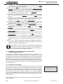
sure in the hydraulic circuit, slowly increase the pressure and watch
closely to observe at which pressure level the carriage is “dragged”
to start moving.
The drag pressure for moving the pipes has to be higher than
2.0 bar.
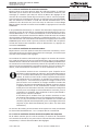
Drag Pressure
230°C
ACT.
3.5bar
Display 21
The START/SET key has to be pressed when the carriage starts moving,
in order to save the drag pressure applicable to this welding to
memory.
Important
The exact drag pressure depends on various conditions (pipe
size and material, position of the machine, etc.) and has to
be determined for every welding individually.
4.4.3 Possibility to Change Welding Parameters
Subsequent to setting the drag pressure, Display 23 shows on the
screen, provided that manual data input is enabled in the Reporting
sub-menu of the Configuration Menu.
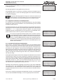
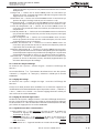
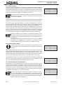
The two screens enabling manual input of welding parameters (Displays 22 and 23) allow value changes using the ñ, ò, ï, ð cursor keys
(se first Info in Sect. 4.1). The START/SET key serves to confirm the
inputs. By pressing the START/SET key, you also make the control unit
go on to the next screen.
Info
The parameters set manually are kept in memory when the
machine is turned off. Only the pressure values are computed
individually for every welding process. If the pipe parameters
change, all parameters have to be set once again. The machine recognizes the change of pipe parameters and brings
the operator directly to the menu that allows changing
them.
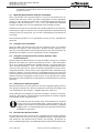
4.4.4 Setting the Maximum Pressure and Starting the Bead Build-up Stage
After butt facing, pipe alignment check, and confirmation of the
welding parameters are done, the welding process proper starts by
setting the maximum pressure that will be reached during the process,
in the bead build-up stage and at the end of the joining stage. While
the welder is setting the maximum pressure dislayed as the nominal
value on the screen, the actual pressure also shows (see Display 24),
and the control software moves on to the next step as soon as the
actual pressure is within tolerance.
At the start of the bead build-up stage, place the heating element
between the pipe butts. The display tells you so (Display 25). If the
heating element does not have the nominal temperature yet at this
point, an information message on the screen tells you so. For the
heating element temperature is continuously monitored by the data
logger. The Insert Heating Element screen is displayed only when the
heating element exhibits the required temperature.
When the heating element is ready in place, press the START/SET key
and set the machine to maximum pressure, so it pushes the pipes
against the heating element. Wait for the weld bead to reach the
required height or width, depending on the used welding standard.
When the nominal bead height, which is also indicated on the display,
is reached, the operator has to press the START/SET key to terminate
the build-up stage.
Bead B. Pr.:030.5bar
Heating Pr.:010.5bar
Heating Tm : 0120 s
Change Tm : 0005 s
Display 22
Cooling t5
Cooling t6
Cool Pr t6
Pres. Ramp
: 0727 s
: 0000 s
:002.0bar
: 012 s
Display 23
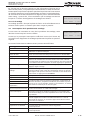
Max. Pressure
230°C
229°C
NOM.
ACT.
16.5bar
3.5bar
Display 24
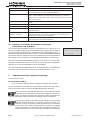
Insert Heating Elem.
222°C  NOM.  16.5bar
221°C  ACT.   0.5bar
Display 25
Bead Height   :2.0mm
Bead B. Time :68 s
230°C  NOM. 16.5bar
229°C  ACT. 12.5bar
Display 26
Version May 2014
HÜRNER SPG 2.0 User’s Manual
EN
15