1
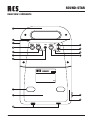
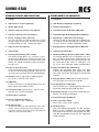
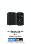
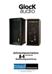
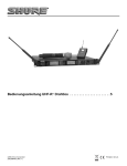
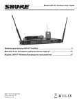
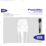
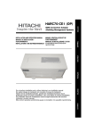
SS-040
SOUND-STAR
OPERATING INSTRUCTIONS / BEDIENUNGSANLEITUNG
- ENGLISH
- DEUTSCH
SOUND-STAR
SAFETY INSTRUCTIONS
SICHERHEITSHINWEISE
Read all instruction before operating!
1. Install equipment as follow condition:
• Install at flat place, not bending curved.
• Do not install near the water and moisture.
• Do not drop objects or spill liquids on to the
inside of amplifier.
• Locate power amplifier away from heat source.
Vor Inbetriebnahme des Gerätes bitten wir Sie die
Sicherheitshinweise aufmerksam zu lesen!
1. Installation nach folgenden Richtlinien:
• Stellen Sie den Verstärker immer auf eine
ebene und stabile Unterfläche.
• Wählen sie eine trockene Umgebung und
stellen sie keine Flüssigkeiten auf das Gerät.
• Vermeiden Sie die Nähe von Heizungen
und anderen Hitzequellen.
2. Keep in mind the following when connecting amplifier:
• Connect the amplifier after reading of manuals.
• Connect each connection of amplifier perfectly,
if not, it maybe caused hum, damage, electric
shock in case of misconnecting.
• To prevent electric shock, do not open top cover.
• Connect the power cord with safety after check
of AC power.
2. Beachten Sie folgendes, wenn sie den
Verstärker anschließen:
• Lesen Sie zuerst die Betriebsanleitung
• Öffnen sie niemals das Gehäuse des Gerätes
ohne den Netzstecker zu ziehen.
• Schließen Sie das Gerät nur an 230 V Netzspannung oder 12 V/DC Notstromversorgung an.
RCS SOUND-SYSTEMS
RCS SOUND-SYSTEME
Thank you for choosing an RCS-portable sound system. Our
products incorporate state-of-the-art design and the finest
quality of materials and workmanship. We’re proud of our
products and appreciate the confidence which you have
shown by selecting an RCS system. I hope you’ll take a few
minutes to review this manual. We’ve incorporated several
unique features into our products and your knowledge of
how to use them will enhance the performance and your
enjoyment of the system.
Vielen Dank, dass Sie sich für ein RCS-Beschallungssystem
entschieden haben. Alle RCS-Systeme werden für grösstmögliche Mobilität und für höchste Ansprüche entwickelt
und hergestellt. RCS-Mobil-Systeme sind leichtgewichtig
und begleiten Sie dank ihrer kompakten Grösse überall hin.
Mit leistungsstarken Verstärkern und wirkungsvollen Lautsprechersystemen kann jedes RCS-System Ihre individuellen
Beschallungsprobleme in Innenräumen und im Freien lösen.
Die gerätespezifischen Eigenschaften ermöglichen es, daß
die Systeme sowohl für Musik wie auch für reine Sprachanwendung verwandt werden können. In weniger als 1 Minute
Aufbauzeit ist fast jedes RCS-System einsatzbereit.
INSPECTION AND INVENTORY OF YOUR SYSTEM
AUSPACKEN UND KONTROLLE DES SYSTEMS
Check unit carefully for damage which may have occurred
during transit. Each RCS product is carefully inspected at the
factory and packed in a special carton for safe transport.
All damage claims must be made with the freight carrier.
Notify the freight carrier immediately if you observe any
damage to the shipping carton or product!
Repack the unit in the carton and await inspection by the
carrier’s claim agent. Notify your dealer of the pending freight claim. Returning your unit for service or repairs Should
your unit require service, contact your dealer.
Gerät senkrecht stellen und Deckkarton öffnen. In einem
Beipack befindet sich evtl. Zubehör. Öffnen Sie nun den
zweiten Karton an seiner Oberseite und ziehen Sie das Gerät
nach oben am eingelassenen Griff heraus.
Bitte überprüfen Sie das Gerät sofort auf evtl. Transportschäden.
Alle Transportschäden müssen sofort bei der Transportfirma reklamiert werden!
Rücksendung: Wenn es nötig sein sollte, ein defektes Gerät zurückzusenden, nehmen Sie bitte Kontakt mit Ihrem
Händler auf. Bitte versenden sie alle Rücksendungen in der
Originalverpackung.
Electromagnetic compatibility and low-voltage guidelines: RCS leaves all devices and products, which are subject to the CE guidelines by certified test laboratories test.
By the fact it is guaranteed that you may sell our devices in Germany and in the European Union domestic market without additional checks.
Elektromagnetische Verträglichkeit und Niederspannungsrichtlinien: RCS läßt alle Geräte und Produkte, die den CE-Richtlinien unterliegen durch zertifizierte Prüflabors
testen. Dadurch ist sichergestellt, daß Sie unsere Geräte in Deutschland und im EU-Binnenmarkt ohne zusätzliche Prüfungen verkaufen dürfen.
2
SOUND-STAR
QUICK USE GUIDE
KURZANLEITUNG
CAUTION with battery-devices: Make sure that the batteries are fully charged before use.
ACHTUNG bei Batteriegeräten: Laden Sie den Akku vor
der ersten Benutzung immer erst vollständig auf.
1. Set the unit in front of your audience on the floor, table or
on a speaker stand. Connect the plug of the mains cable
to a mains socket (230 V~/ 50Hz). If you possess a battery version, the connection to the mains socket is not necessarily.
1. Positionieren Sie Ihr Lautsprechersystem mit oder ohne
Stativ vor Ihrer Zuhörerschaft. Verbinden Sie das Netzkabel mit einer Netzsteckdose (230 V~/ 50Hz). Sollten Sie
eine Akku-Version besitzen, ist die Verbindung mit dem
Stromnetz nicht unbedingt erforderlich.
2. Plug a microphone into the MIC input, or plug an audio
source into the AUX IN input.
2. Schließen Sie ein Mikrophon an der MIC Buchse, bzw.
eine andere Tonquelle an der AUX IN-Buchse an.
3. Set all input level controls to minimum (left position).
3. Drehen Sie alle Volumen-Regler auf Minimum (nach links).
4. Turn the power switch „ON“ (the main switch position is
with nearly all RCS devices on the lower left side). The
red LED light up.
4. Schalten Sie den Hauptschalter auf „ON“ (der Hauptschalter befindet sich bei fast allen RCS-Geräten auf der
unteren linken Seite). Die rote LED leuchtet auf.
5. Slowly increase the level control adjacent to the input
used until desired volume is reached.
5. Drehen Sie nun den VOLUMEN-Regler langsam nach
rechts und steuern Sie so die richtige Lautstärke aus.
FEEDBACK INFORMATION
INFORMATIONEN ÜBER RÜCKKOPPLUNG
What causes feedback?
Feedback is a ringing, howling, or shrill sound that is selfgenerated by the sound system. It is the result of sound from
the speakers being picked up by the microphone(s) in use
and then reamplified by the system. This can form a selfsustaining loop that can damage the sound system if allowed
to continue.
Was ist eine Rückkopplung ?
Eine Rückkopplung ist ein pfeifender, schellender und sehr
greller Ton, der sich selbst erregt. Befinden sich ein Mikrofon
und ein Lautsprecher gleichzeitig in einem Raum, so besteht die Gefahr einer Rückkopplung. Die Voraussetzung
für akustische Rückkopplung ist ein in sich geschlossener
Übertragungskreis. Das Mikrofon nimmt ein Schallereignis
auf, es wird verstärkt und vom Lautsprecher abgestrahlt;
die Schallwellen des Lautsprechers treffen wieder auf das
Mikrofon, werden weiter verstärkt und wiederum dem Lautsprecher zugeführt usw.
How to prevent feedback?
ALWAYS STAND BEHIND THE SPEAKER WHEN USING A
MICROPHONE!
Wie vermeide ich Rückkopplung?
POSITIONIEREN SIE IHR MIKROFON WENN MÖGLICH
IMMER HINTER DEN LAUTSPRECHERN!
CAUTION: Feedback can damage your equipment and
may be hazardous to your hearing!
To avoid feedback, always make sure volume controls are at
minimum before turning unit on. If feedback occurs, immediately reduce the volume.
ACHTUNG: Ein durch Rückkopplung erzeugter Ton kann
zur Zerstörung des Systems und zu Gehörschäden führen!
Um eine Rückkopplung zu vermeiden, sollten Sie die Lautstärke bei Inbetriebnahme auf minimum stellen. Wenn Feedback auftritt, sollten Sie sofort die Lautstärke verringern.
3
SOUND-STAR
REAR VIEW / RÜCKSEITE
1
2
3
11
4
12
5
13
6
14
7
8
9
15
15
10
4
SOUND-STAR
OPERATING ELEMENTS AND CONNECTIONS
BEDIENELEMENTE UND ANSCHLÜSSE
1. Handle
1. Tragegriff
2. UHF-wireless receiver (optional)
2. UHF-Drahtlos-Empfänger (optional)
3. Sturdy ABS casing
3. Stabiles ABS-Gehäuse
4. Volume control for wireless-microphone
4. Lautstärkeregler für Drahtlos-Mikrofon
5. Volume control for wire-microphone
5. Lautstärkeregler für drahtgebundenes Mikrofon
6. Power & charge battery indicator:
The red LED light up during sufficiently internal
voltage supply. If the green LED flash the built-in
charging battery is weak – please recharge it.
6. Spannungs- & Akku-Zustandsanzeige:
Leuchtet rot bei ausreichend interner Spannungsversorgung. Leuchtet die LED grün, ist der Akku zu
schwach und muss wieder aufgeladen werden.
7. Input for wire-microphones
7. Eingangsbuchse drahtgebundenes Mikrofon
8. Cable holder
8. Halterung für Netzkabel
9. Rechargeable battery (12V / 1.2Ah):
The general charge time is 10 – 12 hours. In charging, insert AC power wire and put the switch (15)
at OFF/CHARGE position. To extend the life of the
battery you should immediately replanish the battery after use.
9. Wiederaufladbarer Wechsel-Akku (12V / 1.2Ah):
Die Ladezeit beträgt 10 bis 12 Stunden. Um zu laden, muß der AC Netzstecker angeschlossen sein.
Stellen Sie den Schalter (15) auf AUS/LADEN. Um
die Lebensdauer des Akku zu verlängern, sollten sie ihn nach Gebrauch sofort wiederaufladen.
10. Clips to open the Cover:
Press the two clips easily upward and solve the cover from the device by tilting upward. Now you have
acces to mains connection and rechargeable Battery.
10. Clips zum Öffnen der Abdeckung:
Drücken Sie die beiden Clips leicht nach oben
und lösen die Abdeckung durch Kippen nach oben
vom Gerät. Jetzt haben Sie Zugang zu Netzanschluß
und Akku.
11. AUX IN (Auxiliary signal input -20dB 500Ohm):
To connect a external audio source.
12. LINE OUT:
For the connection of recording equipment or amplifier (signal output 0dB 1K-Ohm)
13. Recieption LED: Light up when a signal is received from the wireless microphone.
14. AUX volume controller
15. Power- and Charge-switch:
up = ON; down = OFF / CHARGE
16. AC-Power plug:
Underneath the cover you will find the mains connection socket. To open the cover, follow the instructions of point 10. During the AC operation via
cable, you can close the cover.
11. Eingangsbuchse AUX (Signal -20dB 500Ohm):
Zum Anschluß einer externen Tonquelle.
12. Ausgangsbuchse LINE-OUT:
Zum Anschluß eines Aufnahmegerätes oder eines
Verstärkers (Signalausgang 0dB 1K-Ohm).
13. Empfangsanzeige: Leuchtet beim Empfang eines
Signals vom Drahtlosmikrophon.
14. Lautstärkeregler für AUX-IN
15. Netz- und Ladeschalter:
oben = EIN ; unten= AUS / LADEN
16. AC Netzstecker:
Unter der Abdeckung befindet sich die Anschlußbuchse für das Netzkabel. Zum öffnen der Abdeckung, gehen sie wie unter Punkt 10 erklärt vor. Während des Netzbetriebs können Sie die Abdeckung
wieder schließen.
5
SOUND-STAR OPTION
WH-800: HANDHELD WIRELESS MICROPHONE / DRAHTLOSES HANDMIKROPHON
1
3
2
5
6
4
7
8
WH-800 FEATURES
WH-800 EIGENSCHAFTEN
This Microphone incorporates ,,Noise-Lock“ dual-squelch
circuitry to reduce interference.
Das Mikrofon verfügt über einen Doppel-Squelch Schaltkreis
mit Pilotton für höchste Übertragungssicherheit.
The optional handheld wireless microphone WH-800 is modular in design.
Das drahtlose Handmikrofon WH-800 ist modular aufgebaut
und besteht aus folgenden Komponenten:
1. Grille:
Protects the microphone capsule and is additionally with
an integrated wind-protection against „POP“ noises.
1. Schutzgitter:
Schützt die Mikrofonkapsel und ist zusätzlich mit einem integrierten Windschutz gegen „POP“-Geräusche versehen.
2. Anti-Rolling colored-ring:
For frequency identification. lts polygonal shape also
prevents the microphone from rolling when placed on a
flat surface.
2. Anti-Roll Kennungsring:
Zur Identifikation des Mikrofons in verschiedenen Farben
erhältlich. Zudem verhindert die Form des Ringes, dass
das Mikrofon wegrollt.
3. Microphone capsule:
The high-fidelity condenser microphone capsule is ideal
for spech and vocals.
3. Mikrofonkapsel:
Die hochwertige Kondensatorkapsel mit hoher Wiedergabefähigkeit ist ideal für Sprache und Gesang.
4. Housing with transmitting unit:
The housing is provided with a special coating, which
dams hand noises. Upper section is connected at capsule module. lnternally, it houses the transmitter PCB and
battery compartment.
4. Gehäuse mit Sendeteil:
Das Gehäuse ist mit einer Spezialbeschichtung versehen, welche Handgeräusche dämmt. An der Oberseite
ist es mit der Mikrophonkapsel verbunden. Innen beherbergt es die Sende-Elektronik und das Batteriefach.
5. Battery Status indicator:
Display power and battery status. When the power
switch is turned ON, the red LED flashes briefly, indicating normal battery status. If after power and the indicator stays lighted, it warns that the battery is weak and
should be replaced.
5. Batterieanzeige:
Spannungs- und Batteriestatus-Anzeige. Beim Einschalten blitzt die rote LED kurz auf und zeigt normalen Batteriezustand an.
Leuchtet die Anzeige permanent, ist die Batterie schwach
und sollte ausgewechselt werden.
6. Power switch:
Turn the microphone ON or OFF
6. EIN-/AUS-Schalter:
Schaltet das Mikrofon EIN bzw. AUS.
7. Battery compartment:
Designed to accommodate one 9V battery or a 7,2V
Akku.
7. Batteriefach:
Zur Verwendung eines 7,2 V Akkus oder einer handelsüblichen 9Volt Batterie.
8. Battery Cap (s. battery installation)
8. Batterie-Deckel (s. Batterie auswechseln)
6
SOUND-STAR OPTION
WH-800 OPERATING INSTRUCTIONS
WH-800 BEDIENUNGSHINWEISE
As the microphone is switched on:
When the power is switched ON, the indicator will flash briefly indicating normal operation.
Einschalten des Mikrofons:
Beim Einschalten leuchtet die Batterieanzeige kurz auf. Leuchtet die LED permanent muss die Batterie ersetzt werden.
During Usage – if you work with the…
Während des Gebrauchs, wenn sie den…
… internal SOUND-STAR UHF-Receiver:
The green indicator beside the Volume controller (MIC1)
light up green if the receiving status is optimal and the signal strength is really good.
… internen SOUND-STAR UHF-Empfänger benutzen:
Das grüne Lämpchen neben dem Lautstärkeregler (MIC1)
leuchtet auf wenn der Sender eingeschaltet ist und ein
ausreichendes Empfangssignal aufgebaut wurde.
… external UHF-Receiver (RU-800):
The SIGNAL LED indicator on the receiver glows. The
more LEDs that glow indicate that the received signal
strength is stronger. If the red LED illuminates it indicates abnormal receiving status and insufficient signal
strength.
… externen UHF-Empfänger (RU-800) benutzen:
Die SIGNAL-LED‘s am Empfänger leuchten grün auf. Je
mehr Lämpchen aufleuchten, desto besser ist die Empfangsstärke. Wenn nur die rote LED leuchtet, signalisert
dies eine anormale bzw. eine zu niedrige Empfangsstärke.
The AUDIO LED indicator on the receiver will illuminate
according to the audio signal strength from the microphone (Level of 1 - 2 LEDs with normal speech usage).
When the red LED light up, it indicates that maximum
sound pressure level has been reached, but it does not
represent distortion.
Die AUDIO-LED‘s am Empfänger leuchten entsprechend
der Audiosignalstärke wenn in das Mikrophon gesprochen wird (Ausschlagpegel von 1 bis 2 Lämpchen bei
normalem Sprachgebrauch). Wenn die rote LED aufleuchtet, ist der maximale Schalldruckpegel erreicht worden (diese LED zeigt nicht Verzerrung an).
When the microphone is not in use:
Make sure that you turn off the microphone after use to
extend the battery life. Remove the battery from the battery
compartment if microphone is not be used for a while. If a
rechargeable battery was used, take it out and recharge it.
Wenn das Mikrofon nicht gebraucht wird…
Vergewissern Sie sich, dass das Mikrofon ausgeschaltet ist,
da ansonsten die Batterie verbraucht wird. Nehmen Sie die
Batterie aus dem Batteriefach, wenn Sie das Mikrofon längere Zeit nicht einsetzen. Wenn sie einen Akku verwenden,
können Sie diesen entnehmen und wieder aufladen.
BATTERY INSTALLATION
BATTERIE EINLEGEN
Unscrew battery cap in a counter-clockwise direction. Insert
a 9-V battery into the battery compartment according to the
correct polarity. The moment the battery touches the terminals, the indicator will flash briefly. This means the polarity
is correct. However, if a flash occurs, this indicates wrong
insertion or that the battery is weak. Please re-insert the
battery according to its correct polarity or exchange it for a
fresh battery.
Schrauben Sie den Batteriedeckel durch drehen gegen denUhrzeigersinn ab. Setzen Sie einen Akku (7.2 Volt) oder eine
9 Volt Batterie ein. Achten Sie dabei auf die korrekte Polariät
(+/–). Danach Batteriedeckel wieder zuschrauben. Die Baterieanzeige sollte nun beim Einschalten kurz aufleuchten.
Ist dies nicht der Fall, ist eventuell die Polarität falsch oder
die Batterie leer. Legen sie dann die Batterie erneut mit der
korrekten Polarität ein bzw. eine neue Batterie.
7
SOUND-STAR OPTION
WB-800: BODYPACK / TASCHENSENDER
1
2
3
4
5
6
7
10
8
9
10
WB-800 BODYPACK (TRANSMITTER)
TASCHENSENDER WB-800
1. Transmitting Antenna:
1/4λ Transmitting antenna. In usage it should be freely as
possible.
1. Sende-Antenne:
1/4λ Antenne, die beim Betrieb möchlichst frei stehen
sollte.
2. Battery Status indicator:
The LED flashes briefly, indicating normal battery status.
If the red LED indicator stays lighted, the battery is weak
and should be replaced.
2. Batterieanzeige:
Leuchtet nur kurz beim Einschalten. Leuchtet permanent, wenn die Batterie gewechselt werden sollte.
3. Power Switch:
Turn the transmitter and the microphone ON or OFF.
3. EIN-/AUS-Schalter:
Schaltet die Spannungsversorgung des Senders und Mikrofons EIN bzw. AUS.
4. AF Input Jack:
For the connection of Lavalier microphone, headset or
guitar.
4. 4-Pin Mini XLR-Stecker:
Zum Anschluss von einem Lavalier- u. Kopfbügel-Mikrofon oder einer Gitarre.
5. ABS Transmitter Housing
5. ABS Gehäuse
6. Frequency group
6. Frequenzcode
7. Gain Control:
Adjusts the desirous input gain (see 8).
7. Regler für Eingangsempfindlichkeit:
Zum justiert der gewünschten Sensibilität (siehe 8).
8. GT/MT Level Select Switch:
Switch GT position for electric guitar usage ONLY.
Gain Control is irrelevant for ,,GT“.
Switch to ,,MT‘ for condenser microphone, wired microphone. Recommended is rather a small adjustment, in
order to avoid feedbacks and over-regulation. Adjust the
optimal volume at the receiver..
8. GT-/MT-Schalter:
Steht der Schalter auf GT, so ist der Eingang auf eine
E-Gitarre abgestimmt.
Auf MT kann die Eingangsempfindlichkeit am kleinen
Poti neben dem Schalter verändert werden. Empfohlen
ist eher eine geringe Einstellung, um Rückkopplungen
und Übersteuerung zu vermeiden. Steuern Sie die optimale Lautstärke am Empfänger aus.
9. Transmitter Housing (transmitter electronic)
10. Battery Compartment
11. Detachable Belt Clip:
Pull arrow direction at release
8
9. Sendergehäuse (Sendeelektronik)
10. Batteriefach
11. Abnehmbare Gurtklammer:
Drehbar zur optimalen Positionierung.
SOUND-STAR OPTION
Plug the microphone connector into the XLR-input jack
and tighten the connecter screw by clockwise direction
as Shawn.
Stecken Sie das Mikrofon an den 4Pin-XLR-Steckers des
Taschensenders. Achten Sie dabei auf die korrekte Position des. Fixieren Sie den Stecker anschließend durch
schrauben im Uhrzeigersinn wie abgebildet.
Topview input connector
Draufsicht Gerätestecker
Technical information about input-Pins:
1 = 2-Wire Electret condenser microphone Capsule
2 = 3-Wire Electret condenser microphone Capsule
3 = Dynamic Microphone
4 = Electric Guitar
5 = Line-in
(Impedance 8K ATT. 10dB; AF 4-Pin Input)
Technische Information zur Pin-Belegung:
1 = 2-Draht Electret Kondensatormikrophone
2 = 3-Draht Electret Kondensatormikrophone
3 = Dynamisches Mikrophone
4 = 1-Draht-Gitarrenanschluß
5 = AUX / Line-Pegel
(Impedanz 8K-Ohm ATT. 10dB; AF 4-Pin Eingang)
BATTERY INSTALLATION
BATTERIE EINLEGEN
Pushing down both snatches on the sides of battery cover to
open it and proceed as shown underneath.
Insert a 9V battery into the battery compartment according
at the correct polarity as shown. Then push up to dose the
battery compartment as shown.
The LED indicator flashes briefly when power on indicating
normal battery status. If an flash occurs it has either no battery, the battery is drained or installed incorrectly. Change
accordingly.
Öffnen Sie den Batteriefachdeckel mit leichtem Druck auf
die seitlich angebrachten Griffe und gehen sie wie unten
abgebildet vor.
Setzen Sie einen Akku (7.2 Volt) oder eine 9 Volt Batterie ein.
Achten Sie dabei auf die korrekte Polariät (+/–). Danach Batteriedeckel wieder zuschrauben. Die Batterieanzeige sollte
nun beim Einschalten kurz aufleuchten. Ist dies nicht der
Fall, ist eventuell die Polarität falsch oder die Batterie leer.
Legen sie dann die Batterie erneut mit der korrekten Polarität
ein bzw. eine neue Batterie. (Einige wenige Batteriemarken
sind nicht kompatibel zum RCS Taschensender!)
9
SOUND-STAR
NOTES/NOTIZEN:
10
SOUND-STAR
SPECIFICATIONS
Power AC:
110 V/120 V or 220 V/240 V
Power DC:
12 V/1.2Ah
Ouput Power:
20/40 Watt
Frequency response:
50 Hz - 12.000 kHz, ± 3 dB
Mic:
Lo-Z, unbalanced, 1/4"-phone
AUX input:
Hi-Z, unbalanced, 1/4"-phone
Line output:
Lo-Z, 1/4"-phone
Options:
UHF-Wireless and div. microphones
Battery:
12 V, 1.2Ah valve regulated sealed lead-acid type rechargeable battery
Chargertime:
10~12 hours
Outside material:
ABS
Dimensions (WxHxD):
185 x 290 x 135 mm
Weight:
2,6 kg
*Specifications subject to change without notice.
11
SOUND-STAR
© Copyright by RCS AUDIO-SYSTEMS GmbH.
Publication and duplication of the contained data only allowed with our strict permission. Veröffentlichung und Vervielfältigung der enthaltenen Daten, auch auszugsweise, nur mit unserer ausdrücklichen Genehmigung.