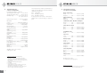
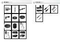
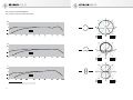
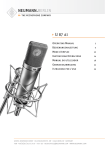
1
TLM 67
Bedienungsanleitung
2
Operating Manual
7
georg neumann gmbh · ollenhauerstr. 98 · 13403 berlin · germany
fon +49 (0)30 / 41 77 24-0 · fax -50 · [email protected] · www.neumann.com
1.
Verlegen Sie Kabel stets so, dass niemand darüber
stolpern kann.
Einleitung
In dieser Anleitung finden Sie alle wichtigen Informationen für den Betrieb und die Pflege des von
Ihnen erworbenen Mikrophons. Lesen Sie diese
Anleitung bitte sorgfältig und vollständig, bevor
Sie es benutzen. Bewahren Sie die Anleitung bitte
so auf, dass sie für alle momentanen und späteren
Nutzer jederzeit zugänglich ist.
Weitergehende Informationen, insbesondere
auch zu den verfügbaren Zubehörteilen und den
Neumann-Servicepartnern, finden Sie auf unserer
Website www.neumann.com. Die Servicepartner
können Sie auch telefonisch unter +49 (0) 30 /
41 77 24 – 0 erfragen.
Halten Sie Flüssigkeiten und elektrisch leitfähige
Gegenstände, die nicht betriebsbedingt notwendig sind, vom Gerät und dessen Anschlüssen fern.
3.
4.
Verwenden Sie das Gerät nur unter den in den
technischen Daten angegebenen Betriebsbedingungen.
Lassen Sie das Gerät auf Raumtemperatur akklimatisieren, bevor Sie es einschalten.
Nehmen Sie das Gerät nicht in Betrieb, wenn es
beim Transport beschädigt wurde.
D
2
5.
Hochpass einstellen
Mit einem Schalter auf der Rückseite des Mikrophons aktivieren Sie ein Hochpassfilter. Dieses
dämpft unerwünschte tiefe Frequenzen (Trittschall, Windgeräusche) oder dient der Kompensation des Nahbesprechungseffektes.
Störschallunterdrückung
Der Übertragungsbereich des TLM 67 reicht bis
unter 20 Hz. Entsprechend empfindlich ist das
Mikrophon natürlich auch für tieffrequente Störungen wie Körperschall oder Wind- und Popgeräusche. Daher empfiehlt sich ggf. die Verwendung einer elastischen Aufhängung, eines Windschutzes und/oder eines Popschirmes.
Kabellängen bis ca. 300 m zwischen Mikrophon
und nachfolgendem Verstärkereingang haben
keinen Einfluss auf den Frequenzgang des Mikrophons.
Lieferumfang
Besprechen Sie das Mikrophon von der Seite aus,
auf der sich das Neumann-Logo befindet.
Mikrophon TLM 67:
Erhöhen Sie an den weiterverarbeitenden Geräten
schrittweise den Lautstärkepegel.
Mikrophon einrichten
Befestigen Sie das Mikrophon auf einem ausreichend stabilen und standfesten Stativ. Verwenden
Sie ggf. eine elastische Aufhängung, um die Übertragung von Körperschallgeräuschen mechanisch
zu unterdrücken. Setzen Sie dafür das Mikrophon
von oben in den Innenkorb ein und schrauben
Sie es mit der Rändelmutter am Innenkorb fest.
Zur Dämpfung von Wind- oder Popgeräuschen
verwenden Sie bei Bedarf einen Wind- oder Popschutz aus unserem Zubehörprogramm.
Diese erhöht die Aussteuerungsgrenze um 10 dB,
um extrem laute Schallereignisse ohne Übersteuerung weiterzuleiten.
Verbinden Sie das Mikrophon über ein geeignetes
Kabel mit dem Mikrophoneingang Ihres weiterverarbeitenden Audiogerätes bzw. mit dem vorgesehenen P48-Speisegerät. Hinweise zur Anschlussbelegung finden Sie im Kapitel Technische Daten.
Achten Sie beim Anschließen von Kabeln auf die
korrekte Verriegelung der Steckverbinder. Verlegen Sie die Kabel so, dass sie keine Stolpergefahr
darstellen.
Inbetriebnahme
Vordämpfung einstellen
Mit einem Schalter auf der Rückseite des Mikrophons kann eine Vordämpfung zugeschaltet werden.
Minimieren Sie an den angeschlossenen Wiedergabe- und Aufnahmegeräten die Lautstärke, bevor
Sie das Mikrophon anschließen.
Die zuschaltbare Dämpfung senkt das Übertragungsmaß um –10 dB und ermöglicht so die Verarbeitung sehr hoher Schalldrücke.
• Mikrophon TLM 67
• Bedienungsanleitung
• Etui
Schließen Sie das Mikrophon nur an Mikrophoneingänge und Speisegeräte an, die
eine 48 V-Phantomspeisung nach IEC 61938
liefern.
Reparatur- und Servicearbeiten dürfen nur von
erfahrenem und autorisiertem Fachpersonal
durchgeführt werden. Wenn Sie das Gerät eigenmächtig öffnen oder umbauen, erlischt die Gewährleistung.
Vorsicht: Sehr laute Geräusche können Ihr
Gehör oder Ihre Lautsprecher schädigen!
Ein schaltbares Hochpassfilter hebt die untere
Grenzfrequenz an und reduziert so den Einfluss
von Nahbesprechungseffekt und Körperschall.
Sicherheitshinweise
Der bestimmungsgemäße Gebrauch dieses Mikrophons ist die Wandlung akustischer in elektrische
Signale.
Kurzbeschreibung
Die Verwendung der Kapsel K 67 und ein spezielles Schaltungsdesign mit charakteristischen
Eigenschaften der Originalröhre EF 86 geben dem
TLM 67 eine Klangabstimmung, die sich an das
U 67 anlehnt.
• Betrieb an unsymmetrischen oder mittengeerdeten Eingängen
• Hinweise zur Pflege des Mikrophons
Zum weltweiten Erfahrungsaustausch unter
Neumann-Anwendern bieten wir das Neumann
Online-Forum an, das sich durch die integrierte
Archivfunktion zu einem umfangreichen KnowHow-Pool entwickelt hat.
2.
Entsorgen Sie das Gerät nach den Bestimmungen
Ihres Landes.
Das TLM 67 ist ein Kondensator-Studiomikrophon
in transformatorloser Schaltungstechnik (TLM)
und verfügt über die Richtcharakteristiken Kugel,
Niere und Acht.
Auf unserer Website www.neumann.com finden
Sie in der Rubrik Downloads ergänzend folgende
PDF-Dateien:
Vorsicht: Eine falsche Versorgungsspannung
kann das Mikrophon beschädigen!
Schließen Sie das Mikrophon ausschließlich an
ein Netzgerät, einen Mikrophon-Vorverstärker,
ein Mischpult oder anderes Gerät mit 48 V-Phantomspeisung nach IEC 61938 an. Sie können alle
P48-Speisegeräte verwenden, die mindestens
3,5 mA je Kanal abgeben.
Verwenden Sie zum Reinigen keine Lösungsmittel
oder aggressiven Reinigungsmittel.
sicherheitshalber während des Umschaltens den
Signalpegel der nachfolgenden Geräte.
Mikrophon anschließen
Tontest
Sprechen Sie das Mikrophon einfach nur an. Anpusten oder „Anploppen“ führt zu gefährlichen
Schalldruckpegeln.
6.
Außerbetriebnahme und Aufbewahrung
Stellen Sie die Vorverstärkung (Gain) Ihres weiterverarbeitenden Gerätes so ein, dass bei höchstem
Pegel keine Verzerrungen auftreten.
Verringern Sie vor der Außerbetriebnahme und
Abziehen von Kabeln den Lautstärkepegel Ihres
weiterverarbeitenden Gerätes.
Richtcharakteristik wählen
Es stehen drei Charakteristiken zur Auswahl, die
eine individuelle Anpassung an die Aufnahmesituation ermöglichen: Kugel, Niere und Acht. Den
Schiebeschalter für die Richtcharakteristik finden
Sie auf der Vorderseite unterhalb des Korbes.
Schalten Sie erst dann die Phantomspeisung
aus bzw. trennen Sie erst dann die Kabelverbindungen.
Beim Umschalten der Richtcharakteristik kann für
einen Zeitraum bis ca. 30 s ein erhöhter Rauschpegel auftreten. Dieser entsteht durch die elektrische Umladung der Mikrophonkapsel auf die
jeweils notwendige Vorspannung und ist kein
Zeichen für ein Fehlverhalten. Reduzieren Sie
Ziehen Sie beim Lösen von Kabeln stets nur an
den Steckverbindern und nicht am Kabel.
Mikrophone, die nicht im Einsatz sind, sollte man
nicht auf dem Stativ einstauben lassen. Wird ein
Mikrophon längere Zeit nicht verwendet, sollte es
bei normalem Umgebungsklima staubgeschützt
aufbewahrt werden. Verwenden Sie hierfür einen
nicht fusselnden, luftdurchlässigen Staubschutzbeutel oder die Originalverpackung des Mikrophons.
3
D
7.
8.
Fehlercheckliste
Fehler
▶ Mögliche Ursachen
▶ Abhilfe
Keine
Funktion
Phantom-Speisespannung am
Mischpult oder am Speisegerät nicht
eingeschaltet.
Überprüfen Sie die entsprechenden Einstellungen auf dem Kanalzug.
Das Speisegerät ist nicht mit dem
Netzanschluss verbunden oder
Batterie fehlt.
Überprüfen Sie Netzanschluss oder Batterie des
Speisegeräts.
Keine Signalübertragung
Das Mikrophon ist nicht mit dem
richtigen MikrophonverstärkerEingang des nachfolgenden Gerätes
verbunden.
Überprüfen Sie den Signalweg
Ton verzerrt
Falsch eingestellte Eingangsempfindlichkeit oder Vorverstärkung des
nachfolgenden Verstärkers.
Verringern Sie die Eingangsempfindlichkeit oder
Vorverstärkung des nachfolgenden Gerätes so,
dass eine ausreichende Aussteuerungsreserve
bleibt.
Zu hohe Schalldrücke im aufzunehmendenTonsignal.
Schieben Sie den Schalter für die Vordämpfung
auf –10 dB.
Übersteuerung tieffrequenter Tonanteile durch Nahbesprechungseffekt.
Schieben Sie den Schalter für das Hochpassfilter
auf [Symbol].
Windeinfluss
Benutzen Sie einen geeigneten Windschutz
(Zubehör).
Explosivlaute
Benutzen Sie einen geeigneten Popschutz
(Zubehör).
Richtcharakteristik nicht beachtet
Prüfen Sie, ob das Mikrophon von der richtigen
Seite angesprochen wird. Orientieren Sie sich
am Neumann-Logo.
Ton klingt dumpf,
räumlich
Aktivieren Sie ggf. den entsprechenden Eingang
auf dem zugeordneten Kanalzug des Mischpults.
Korrigieren Sie ggf. die Einstellung der Richtcharakteristik.
Technische Daten und
Anschlussbelegungen
Zulässige klimatische Verhältnisse:1)
Betriebstemperaturbereich...............0 °C … +70 °C
Lagerungstemperaturbereich ...... –20 °C … +70 °C
Feuchtebereich ..... 0 %…90 % rel. hum. bei +20 °C
0 %…85 % rel. hum. bei +60 °C
Akust. Arbeitsweise ................... Druckgradientenempfänger
Richtcharakteristik .................... Kugel/Niere/Acht
Übertragungsbereich ......................20 Hz...20 kHz
Feldübertragungsfaktor2) ............................................ 10/18/9 mV/Pa
Nennimpedanz............................................ 50 Ohm
Nennlastimpedanz .................................1000 Ohm
Das Mikrophon besitzt einen symmetrischen,
übertragerlosen Ausgang. Der 3-polige XLR-Steckverbinder weist folgende normgerechte Belegung
auf:
Pin 1:
Pin 2:
Pin 3:
0 V/Masse
Modulation (+Phase)
Modulation (–Phase)
Bei einem Schalldruckanstieg vor der vorderen
Membran tritt an Stift 2 eine positive Spannung
auf.
Geräuschpegelabstand3),
CCIR4) .................................................. 65/70/64 dB
Geräuschpegelabstand3),
A-bewertet4) ........................................78/83/77 dB
Ersatzgeräuschpegel,
CCIR4) .................................................. 29/24/30 dB
Ersatzgeräuschpegel,
A-bewertet4) ..................................... 16/11/17 dB-A
Grenzschalldruckpegel (Röhrencharakteristik)5)
für k < 0,5 % .................................. 110/105/111 dB
für k < 5 % .......................................130/125/131 dB
Max. Ausgangsspannung für k < 5 %.............–1 dBu
Stromversorgung ............................................... P48
Erforderliche Steckverbinder:
Mikrophon .................................................... XLR 3 M
Gewicht ...........................................................490 g
Abmessungen ................................. Ø 56 x 200 mm
94 dBSPL entspr. 1 Pa = 10 µbar
0 dB entspr. 20 µPa
1)
2)
3)
4)
5)
D
4
Alle Werte für nicht-kondensierende Feuchtigkeit.
Die Werte gelten für saubere, gepflegte Mikrophone bzw.
Mikrophonkapseln. Schmutzablagerungen jeglicher Art
auf Kapseln oder Membranen können die genannten Werte
einschränken.
bei 1 kHz an 1 kOhm Nennlastimpedanz
bezogen auf 94 dB SPL
nach IEC 60268-1;
CCIR-Bewertung nach CCIR 468-3, Quasi-Spitzenwert;
A-Bewertung nach IEC 61672-1, Effektivwert
Klirrfaktor des Mikrophonverstärkers bei einer Eingangsspannung, die der von der Kapsel beim entsprechenden
Schalldruck abgegebenen Spannung entspricht.
5
D
9.
Ausgewähltes Zubehör*
(Fotos im Anhang)
1.
This manual contains essential information for the
operation and care of the microphone you have
purchased. Please read the instructions carefully
and completely before using the product. Please
keep this manual where it will be accessible at all
times to all current and future users.
Elastische Aufhängungen
EA 87........................ni ................ Best.-Nr. 007297
EA 87 mt ..................sw ............... Best.-Nr. 007298
Mikrophonneigevorrichtung
MNV 87 ....................ni ................ Best.-Nr. 006804
MNV 87 mt ...............sw ............... Best.-Nr. 006806
Do not use solvents or aggressive cleansers for
cleaning purposes.
Introduction
Dispose of the equipment in accordance with the
regulations applicable to the respective country.
3.
Additional information, in particular concerning available accessories and Neumann service
partners, can be found on our website: www.neumann.com. Information about service partners
can also be obtained by telephone: +49 (0) 30 /
41 77 24 - 0.
Stativgelenke, weitere mechanische Adapter
DS 120 .....................sw ............... Best.-Nr. 007343
SG 87........................sw ............... Best.-Nr. 008619
Use of the K 67 capsule and a special circuit design with characteristics based on the original EF
86 tube give the TLM 67 a sound quality similar to
that of the U 67.
The following related files are available in PDF
format in the Downloads section of our website
www.neumann.com:
Tisch- und Fußbodenständer
MF 3 .........................sw ............... Best.-Nr. 007321
MF 4 .........................sw ............... Best.-Nr. 007337
MF 5 .........................gr ................ Best.-Nr. 008489
• Operation with Unbalanced or Center Tap
Grounded Inputs
• Some Remarks on Microphone Maintenance
Our Neumann online forum enables Neumann
users worldwide to share their experiences.
Through its integrated archive function, the forum
has developed into an extensive knowledge pool.
Schaumstoff windschutz
WS 87 .......................sw ............... Best.-Nr. 006753
Popschutz
PS 15 .......................sw ............... Best.-Nr. 008472
PS 20 a ...................sw ............... Best.-Nr. 008488
Brief description
The TLM 67 is a condenser studio microphone
with transformerless (TLM) circuit technology the
directional characteristics omnidirectional, cardioid and figure-8.
A switchable high-pass filter increases the lower
cutoff frequency, thus reducing the influence of
the proximity effect and structure-borne sound.
The pre-attenuation switch reduces the microphone sensitivity by 10 dB, thus allowing the processing of very high sound pressure levels.
4.
Equipment supplied
TLM 67 microphone:
Batteriespeisegerät
BS 48 i .....................sw ............... Best.-Nr. 006494
BS 48 i-2 .................sw ............... Best.-Nr. 006496
Netzgerät
N 248 EU .................sw ............... Best.-Nr. 008537
N 248 US .................sw ............... Best.-Nr. 008538
N 248 UK .................sw ............... Best.-Nr. 008539
Anschlusskabel
IC 3 mt .....................sw ............... Best.-Nr. 006543
IC 4 ..........................ni ................ Best.-Nr. 006547
IC 4 mt .....................sw ............... Best.-Nr. 006557
Verbindungskabel
AC 25 .......................ni ................ Best.-Nr. 006600
Bedeutung der Farbcodierungen:
ni = nickel, sw = schwarz, gr = grau
* Ausführliche Beschreibungen und weitere Artikel finden Sie
in unserem Zubehörkatalog oder unter www.neumann.com
6
2.
Safety instructions
• TLM 67 microphone
• Operating manual
• Case
The microphone has the intended purpose of converting acoustic signals into electrical signals.
Connect the microphone only to microphone
inputs and devices which supply 48 V of phantom power in accordance with IEC 61938.
Repairs and servicing are to be carried out only
by experienced, authorized service personnel.
Unauthorized opening or modifi cation of the
equipment shall void the warranty.
Use the equipment only under the conditions
specified in the “Technical data” section.
Allow the equipment to adjust to the ambient temperature before switching it on.
Do not operate the equipment if it has been damaged during transport.
Always run cables in such a way that there is no
risk of tripping over them.
Unless required for operation, ensure that liquids
and electrically conductive objects are kept at a
safe distance from the equipment and its connections.
5.
Setup
Mounting the microphone
Attach the microphone to a stable, sturdy stand.
Use an elastic suspension, if necessary, for the
mechanical suppression of structure-borne noise.
For this purpose set the microphone into the inner
cage from above, and secure it to the inner cage
with the threaded nut. If required, use a windscreen or popscreen from our range of accessories in order to suppress wind or pop noise.
Connecting the microphone
Caution: An incorrect supply voltage can damage the microphone!
Attach the microphone only to a power supply
unit, a microphone preamplifier, a mixing console
or other equipment which has phantom power
with 48 V (P48), in accordance with IEC 61938.
Any P48 power supply equipment can be used
which supplies at least 3.5 mA per channel.
7
EN
Caution: Very loud noise can damage loudspeakers or your hearing!
Setting the high-pass filter
The high-pass filter is activated by means of a
switch on the back of the microphone. It can be
used to suppress low-frequency interference (e.g.
caused by impact sound or wind noise) or to compensate for the proximity effect.
Minimize the volume of connected playback and
recording equipment before connecting the microphone.
Using a suitable cable, connect the microphone
to the microphone input of the audio equipment
to be used for subsequent processing, or to the
designated P48 power supply equipment. Information concerning connector assignment can be
found in the “Technical data” section.
Address the microphone from the front, the side
on which the Neumann logo is located.
Gradually increase the volume of the connected
equipment
Set the gain of the connected equipment so that
no distortion occurs at the highest sound pressure level.
Selecting the directional characteristic
There are three selectable directional characteristics, which allow the microphone to be adapted
to individual recording situations: omnidirectional, cardioid and figure-8. The slide switch for the
directional characteristics is located on the front
of the microphone, below the headgrille.
When the directional characteristic is changed,
an increased noise level may occur for a period of
approximately 30 seconds. This does not indicate
a malfunction, but arises due to the electrical
recharging of the microphone capsule to the appropriate bias. As a precaution, reduce the signal
level of connected equipment when changing the
directional characteristic.
▶ Possible causes
▶ Solution
Microphone not
operating
The phantom power supply voltage is
not switched on at the mixing console
or at the power supply equipment
Check the corresponding channel settings
The power supply equipment is not
connected to the power supply line or
there is no battery
Check the connection to the power supply
line or check the battery of the power supply
equipment
No signal
transmission
The microphone is not connected
to the correct microphone amplifier
input of the subsequent equipment
Check the signal path
Distorted sound
Incorrect input sensitivity or gain
setting of subsequent amplifier
Decrease the input sensitivity or gain of the
subsequent device so as to provide sufficient
headroom
Excessive sound pressure level of the
signal to be recorded
Slide the pre-attenuation switch to –10dB.
Shutdown and Storage
Overloading with low frequencies due
to the proximity effect
Slide the switch for the high-pass filter to
<Symbol>
Before switching off the microphone or disconnecting the cables, reduce the volume of connected equipment.
Wind effects
Use an appropriate windscreen (accessory)
Plosives
Use an appropriate popscreen (accessory)
Incorrect directional characteristic
Disconnect the cables.
Check to ensure that the microphone is being
addressed from the correct side, as designated
by the Neumann logo.
When disconnecting a cable, always pull only on
the connector and not on the cable itself.
If necessary, correct the setting for the directional characteristic
Sound test
Simply speak into the microphone. Do not blow
into the microphone or subject it to pop noise,
since this can easily result in hazardous sound
pressure levels.
When connecting the cables, ensure that the connectors are locked correctly. Run the cables in
such a way that there is no risk of tripping over
them.
6.
Troubleshooting
Problem
Suppressing noise interference
The frequency response of the TLM 67 extends
below 20 Hz. The microphone is of course correspondingly sensitive to low-frequency interference such as structure-borne noise and wind or
pop noise. Depending upon the situation, the use
of an elastic suspension, a windscreen and/or a
popscreen is therefore recommended.
Cable lengths of up to approximately 300 m between the microphone and the subsequent amplifier input have no effect on the frequency response of the microphone.
7.
Only then should the phantom power be switched
off.
Sound is muffled
and reverberant
If necessary, activate the appropriate input
on the corresponding channel of the mixing
console
Microphones which are not in use should not be
allowed to remain on the stand gathering dust. A
microphone which is unused for a prolonged period should be stored under normal atmospheric
conditions, and should be protected from dust.
For this purpose, use a lint-free, air-permeable
dust cover or the original packaging of the microphone.
Setting the pre-attenuation
Pre-attenuation is activated by means of a switch
on the back of the microphone. It increases the
maximum signal level by 10 dB, in order to avoid
overloading when transmitting signals at extremely high sound pressure levels.
EN
8
9
EN
8.
Technical data and
connector assignments
The microphone has a balanced, transformerless
output. The 3-pin XLR connector has the following
standard pin assignments:
Permissible atmospheric conditions1)
Operating temperature range...........0 °C to +70 °C
Storage temperature range ...........–20 °C to +70 °C
Humidity range .....................0 % to 90 % at +20 °C
0 % … 85 % at +60 °C
Pin 1:
Pin 2:
Pin 3:
Acoustical op. principle .............Pressure gradient
transducer
Directional
pattern............................... Omni/cardioid/figure-8
Frequency range ............................ 20 Hz to 20 kHz
Sensitivity2) .................................... 10/18/9 mV/Pa
Rated impedance ....................................... 50 ohms
Rated load impedance ......................... 1000 ohms
Signal-to-noise ratio3),
CCIR4) .................................................. 65/70/64 dB
Signal-to-noise ratio3),
A-weighted4) ........................................78/83/77 dB
Equivalent noise level,
CCIR4) .................................................. 29/24/30 dB
Equivalent noise level,
A-weighted4) ..................................... 16/11/17 dB-A
Max. SPL 5)
for THD < 0.5 % ............................ 110/105/111 dB
for THD < 5 % ..................................130/125/131 dB
Max. output voltage for THD > 5 % ...............–1 dBu
Power Supply ..................................................... P48
Required connectors:
Microphone ...................................................XLR3M
Weight .............................................................490 g
Dimensions .................................... Ø 56 x 200 mm
94 dBSPL equiv. to 1 Pa = 10 µbar
0 dB equiv. to 20 µPa
0 V/Ground
Modulation (+phase)
Modulation (–phase)
A sound pressure rise in front of the front diaphragm causes a positive voltage to appear at
pin 2.
9.
Selected Accessories*
(see photos in appendix)
Elastic Suspensions
EA 87........................ni ..................Cat. No. 007297
EA 87 mt ..................blk ................Cat. No. 007298
Auditorium Hanger
MNV 87 ....................ni ..................Cat. No. 006804
MNV 87 mt ...............blk ................Cat. No. 006806
Stand Mounts, Misc. Mechanical Adapters
DS 120 .....................blk ................Cat. No. 007343
SG 87 .......................blk ................Cat. No. 008619
Table and Floor Stands
MF 3..........................blk ................Cat. No. 007321
MF 4 .........................blk ................Cat. No. 007337
MF 5 .........................gry ................Cat. No. 008489
Foam Windscreens
WS 87 .......................blk ................Cat. No. 006753
Popscreen
PS 15 .......................blk ................Cat. No. 008472
PS 20 a ...................blk ................Cat. No. 008488
Battery Supply
BS 48 i .....................blk ................Cat. No. 006494
BS 48 i-2 .................blk ................Cat. No. 006496
Power Supply
N 248 EU .................blk ................Cat. No. 008537
N 248 US .................blk ................Cat. No. 008538
N 248 UK .................blk ................Cat. No. 008539
Connecting Cables
IC 3 mt ....................blk ................Cat. No. 006543
IC 4 ...........................ni ..................Cat. No. 006547
IC 4 mt .....................blk ................Cat. No. 006557
Adapter Cables
AC 25 .............................................Cat. No. 006600
1)
2)
3)
4)
5)
EN
10
All values are for non-condensing humidity.
The values are valid for clean and well-looked-after
microphones or microphone capsules, respectively. Any
kind of pollution of capsules and membranes may restrict
the said values.
at 1 kHz into 1 kohm rated load impedance.
re 94 dB SPL
according to IEC 60268-1;
CCIR-weighting acccording to CCIR 468-3, quasi peak;
A-weighting according to IEC 61672-1, RMS
THD of microphone amplifi er at an input voltage equivalent to the capsule output at the specifi ed SPL.
Meaning of color codes:
ni = nickel, blk = black, gry = grey
* Detailed descriptions and additional articles can be found
in our accessories catalog or at: www.neumann.com
11
EN
12
EA 87 (mt)
MNV 87
DS 120
N 248
SG 87
MF 3
MF 4
AC 25
MF 5
WS 87
PS 15
PS 20 a
BS 48 i
BS 48 i-2
IC 3 mt
IC 4 (mt)
13
10. Frequenz- und Polardiagramme
10. Frequency responses and polar patterns
gemessen im freien Schallfeld nach IEC 60268-4, Toleranz ±2 dB
measured in free-fi eld conditions (IEC 60268-4), tolerance ±2 dB
14
15
Haftungsausschluss
Die Georg Neumann GmbH übernimmt keinerlei Haftung für einen Gebrauch des Produkts, der von den in der Bedienungsanleitung genannten
technischen Voraussetzungen abweicht (z.B. Bedienungsfehler, falsche
Spannung, Abweichung von empfohlenen Korrespondenzgeräten). Dies
gilt auch dann, wenn auf mögliche Schäden bei abweichendem Gebrauch
hingewiesen wurde. Jegliche Geltendmachung von Schäden und Folgeschäden, die dem Benutzer aufgrund eines solchen abweichenden Gebrauchs
entstehen sollten, wird ausgeschlossen. Ausgenommen von diesem Haftungsausschluss sind Ansprüche aufgrund des Produkthaftungsgesetzes.
Disclaimer
The product is sold “as-is” and the customer is assuming the entire risk as
to the product’s suitability for his needs, its quality and its performance. In
no event will Neumann be liable for direct, indirect, special, incidental or
consequential damages resulting from any defect in the product or from its
use in conjunction with any microphones / products from other manufacturers, even if advised of the possibility of such damages.
Konformitätserklärung
Die Georg Neumann GmbH erklärt, dass dieses Gerät die anwendbaren CE-Normen und -Vorschriften erfüllt.
®
Neumann ist in zahlreichen Ländern eine eingetragene Marke der Georg Neumann GmbH.
Declaration of Conformity
Georg Neumann GmbH hereby declares that this device conforms to
the applicable CE standards and regulations.
®
Neumann is a registered trademark of the Georg Neumann GmbH in
certain countries.
Irrtümer und technische Änderungen vorbehalten • Errors excepted, subject to changes
Printed in Germany • Publ. 04/08 527752