1
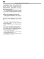
1. Fit the SDS-plus adapter P into the SDS-plus chuck as
described above.
2. Drill chucks with 1/2” x 20 UNF mounting threads can
be screwed onto the mounting shaft. Drill bits with cylindrical
shank or screwdriver bits N can be in-serted directly into the
chuck I.
2. Changing the position of the auxiliary handle
1. Unscrew the auxiliary handle M in an anticlockwise
direction.
2. Turn the auxiliary handle M to the required position.
3. Screw the auxiliary handle M in place again.
3. Setting the depth gauge
Make sure before you start that drill-bit is inserted in the
SDS-Plus chuck.
1. Slightly loosen the fixing wing nut K.
2. Hold the bit tip against the work surface. Push the depth
gauge L against the work surface, to the same depth as the
length of the bit.
3. Read the value in mm off the scale on the depth gauge
L and subtract the required drill depth.
4. Tighten the fixing wing nut K and adjust the resulting
value for the depth stop.
4. Mains connection
Warning! Connect only to a single-phase AC current supply
and only to the mains voltage specified on the rating plate.
Connection to sockets without earth protec-tion is possible as
the appliance features protective class II insulation according
to European Standard EN50114. Radio interference
suppression complies with the European Standard EN
55014.
FUNCTIONS
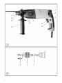
1. Speed selection (Fig.1)
The speed can be controlled in infinitely variable steps by
adjusting finger pressure on the On-/off switch H. Maximum
speed is set up by handwheel C.
2. Switching over between modes (Fig.1)
For switching over between modes lever E has to be turned.
To activate this lever, first press the button D.
WARNING! Only turn the lever E when the machine has
stopped.
3. Switching between forward and reverse (Fig.1)
Select direction of rotation with reversing lever G as shown
on label F.
Only change directions when the machine has stopped.
4. Switching the tool on and off (Fig.1)
Intermittent use
Switching on: Press trigger switch H.
Switching off: Release trigger switch H.
Continuous use
Switching on: Press the On-/off switch H and then the locking
button I, after that release on-off switch.
Switching off: Press the On-/off switch H and then release. The speed can be controlled continuously during the
operation by adjusting finger pressure on the On-/off switch.
OPERATION
Hammer-drilling
1. Set the following adjustments before starting work:
- Lever E in appropriate position.
- Clockwise rotation.
2. Fit the SDS-plus drill.
3. Place the drill against the material before switch-ing it
on, press it until the lengthways play is taken up, then switch
on and work exerting light pres-sure (e.g. 30N).
Note: Exerting greater pressure does not increase the
machine’s effectiveness!
Tips on drilling in masonry:
• Take the drill out of the hole from time to time to re-move
dust.
• Switch to percussion-drilling for concrete, hard bricks
and tiles, stone and hard cement (but not when drilling the
surface of marble).
• For tiles, paving-stones, soft bricks and tiles, soft
cement, breeze-block and plaster, switch to normal drilling.
• Use percussion carbide-tipped masonry drill-bits.
• When drilling a hard, smooth surface (e.g. tiles), cover
the point to be drilled with adhesive tape in order to prevent
the drill tip from skidding.
NOISE AND VIBRATION
This tool has been designed and made to reduce noise to a
minimum. However, in spite of this, in certain circumstances
the maximum noise level in the place of work could exceed 85
dBA. In this case, the operator should wear ear protection.
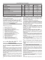
The machine’s noise and vibration levels, measured in
compliance with EN50144, usually reach:
Acoustic pressure = 88 dB(A)
Sound-power level = 99 dB(A)
Use ear protection!
Vibration acceleration = 8,0 m/s²
ACCESSORIES
Accessories and their corresponding order number can be
found in our catalogues.
MAINTENANCE AND CARE
WARNING-Always unplug the machine before carrying out
work on it.
- When you notice a decrease in hammer output, take the
machine to an Official Service Centre.
- Tool inspection: Using a blunt cutting tool leads to less
efficient work and could damage the motor, there-fore cutting
tools should be sharpened or replaced as soon as any wear
is noticed. Daily: Clean the tool-holder.
- Inspect the mounting screws: Regularly inspect all the
mounting screws and ensure they are firmly tight-ened.
Should any screw be loose, tighten it immedi-ately. Failure to
do so could put you at serious risk.
- Motor maintenance: Take the utmost care to ensure
that the motor winding is not damaged and does not become
damp with oil or water.
- Brush replacement: The brushes disconnect automatically and should be replaced after 150-200 hours use or
when they are less than 10 mm long. Have them replaced by
an Official Service Centre.
- Clean the machine thoroughly after each use with a
blast of dry air.
- The vents of the machine should be kept clear at all
times.
- Check that the mains lead is in good condition. If it is not,
take it to an Official Service Centre to have it re-placed.
- Use only Felisatti accessories and spares. The parts the
changing of which is not covered in this instruction manual,
should be replaced in a Felisatti Official Ser-vice Centre (See
Warranty/Official Service Centre ad-dress leaflet).