1
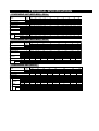
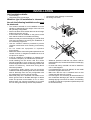
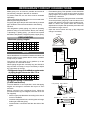
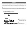
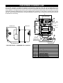
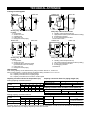
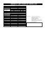
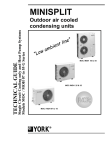
INSTALLATION & OWNER'S
MANUAL GUIDE
MINISPLIT CONDENSING UNIT
Models
MOC-MOH 07-65
SAFETY
Installation and maintenance of this air conditioning system should only be carried out by trained and qualified personnel.
Regular maintenance operations such as cleaning the coils and air filters must be performed to keep the units in proper
operating condition.
CAUTION
Before undertaking any work on the unit, make sure that the power supply has been disconnected.
ELECTRICAL CONNECTIONS
GENERAL PRECAUTIONS
All electrical wiring and connections must comply with
local standards. Power supply cord and interconnection
cord used must not be lighter than Polychloroprene
sheated cord (245 IEC 57 or H05RN-F).
Disconnecting device must have a contact separation of
at least 3 mm.
Check that the power supply available agrees with
nameplate voltage.
Use adequate line protection.
The unit must be grounded.
CRANK CASE HEATER
For units fitted with crankcase heater, the heater MUST
be on for a minimum of 6 hours before starting
compressor. Failure to observe this precaution may result
in damage to the compressor or reversing valve.
OUTDOOR UNITS
The units are shipped complete with a charge of R22 / R-407C refrigerant sufficient for a piping length of 7.5 metres.
Four vibration absorbing mounts are delivered with each unit as well as a drainage elbow connector for condensate
drain connection (on heat pump models only).
From size 25 upwards, outdoor units are fitted with transport handles to facilitate handling and placement.
Every compressor is delivered with a sound-proofing wrap to reduce noise levels to a strict minimum.
The unit support plate is shaped in such a way that water produced during defrost operations on heat pump units is
collected at a single point where it can easily drained off. No accessory drain pan is required.
TECHNICAL SPECIFICATIONS
CONDENSING UNIT (MOC-MOH) - 50 Hz
Models
Power Supply
Power Consumption
Running Current
Refrigerant Type
Refrigerant Charge
Compressor
Dimension
Weight
Piping
Pipe Size
Outdoor
Unit
V/Ph/Hz
Ph
kW
A
gr
Qty
Compressor Type
Height
mm
Width
mm
Depth
mm
kg
Type
Suction
inch
Liquid
inch
07
09
12
18
1
0.817
3.77
1
0.957
4.42
1
1.257
5.92
1
1.82
8.42
620 / 650 900 / 1,000 920 / 1,050
1
1
1
Rotary
492
492
492
764
764
764
230
230
230
38
39
41
3/8
1/4
3/8
1/4
MOC-MOH
25
35
40
45
55
220-240/1/50 or 380-415/3/50
1
3
1
3
1
1
3
3
2.71
2.64
3.29
3.216
3.2
3.7
4.62
5.461
12.8
5.02
15.8
3.16
18.8
21.0
8.62
10.22
R-22
1,750
2,600
3,900
3,650 3,000
3,800
1
1
1
1
1
1
Reciprocating
Scroll
Reciprocating
696
900
1,142
1,142 1,142
1,142
850
850
1,060
1,060
850
1,060
287
285
345
345
285
345
70
92
103.5
122.5
90
129
Flare + Nuts
5/8
5/8
5/8
3/4
3/4
3/4
3/8
3/8
3/8
3/8
3/8
3/8
1,620
1
590
820
280
63
1/2
1/4
5/8
3/8
65
3
5.87
11.22
4,700
1
Scroll
1,142
1,060
345
134
3/4
3/8
CONDENSING UNIT (MOC-MOH) - 60 Hz
Models
Power Supply
Power Consumption
Running Current
Refrigerant Type
Refrigerant Charge
Compressor
Dimension
Weight
Piping
Pipe Size
Outdoor
Unit
V/Ph/Hz
Ph
kW
A
gr
Qty
Compressor Type
Height
mm
Width
mm
Depth
mm
kg
Type
Suction
inch
Liquid
inch
09
12
18
1
0.97
4.8
1
1.2
5.5
1
2.314
13.62
900/1,000
920/1,050
1
1
Rotary
492
492
764
764
230
230
39
41
3/8
1/4
1,650
1
590
820
280
63
1/2
1/4
5/8
3/8
07G
09G
12G
1
0.777
3.52
1
0.937
4.32
MOC-MOH
25
35
208-230/1/60 or 460/3/60
1
1
3
3.024
3.65
3.995
14.02
16.77
6.67
R-22
1,750
2,600
1
1
Reciprocating
696
900
850
850
287
285
70
92
Flare + Nuts
5/8
5/8
3/8
3/8
45
55
65
3
6.74
11.24
3
7.01
12.04
3,000
1
3,800
1
1,142
850
285
104
1,142
1,060
345
129
5,500
1
Scroll
1,142
1,060
345
134
3/4
3/8
3/4
3/8
3/4
3/8
3
5.618
8.7
CONDENSING UNIT (R407C)
Models
Power Supply
Power Consumption
Running Current
Refrigerant Type
Refrigerant Charge
gr
Qty
Compressor Type
Height
mm
Dimension
Width
mm
mm
Depth
Weight
kg
Cooling
kg
Heating
Type
Piping
Suction
inch
Pipe Size Liquid
inch
Compressor
Outdoor Unit
Outdoor
Unit
V/Ph/Hz
Ph
kW
A
850/1000
1
720/1000
1
1
1.34
6.12
492
764
230
37
38
492
764
230
38
40
1150
1
Rotary
492
764
230
42
43
3/8
1/4
3/8
1/4
1/2
1/4
MOC-MOH
25G
35G
18G
220-240/1/50 or 380-415/3/50
1
1
1
3
2.658
3.729
3.489
1.77
12.42
18.47
7.07
8.12
R-407C
2100
3000/2500 3000/2500
1880
1
1
1
1
696
850
287
68
69
Flare + Nuts
5/8
5/8
3/8
3/8
590
820
280
62
63
45G
55G
3
4.868
9.48
3
5.168
13.94
900
1060
345
107
109
3000
1
Scroll
1142
1060
345
127
129
5/8
3/8
3/4
3/8
4000
1
1142
1060
345
127
129
3/4
3/8
DIMENSIONS
OVERALL DIMENSIONS
MOC/MOH 07-18
MOC/MOH 25-35
MOC/MOH 40-65
D
W
W
D
W
D
H
H
H
Unit dimensions are shown in Technical Specification table.
OUTDOOR UNIT CLEARANCES
A minimum of clearance is necessary around the units to ensure proper air circulation and easy access for maintenance.
MOC/MOH 07-18
MOC/MOH 25-35
MOC/MOH 40-65
A
A
A
B
D
B
D
B
D
E
E
E
C
C
MOC/MOH (mm)
07-18
25
35
40
45
55
65
A
400
200
200
200
200
200
200
B
200
400
400
400
400
400
400
C
100
100
100
100
100
100
100
D
600
210
210
300
210
300
300
E
190
600
800
800
800
800
800
NOTE
To prevent ice build up beneath the unit during
winter operation, it may be necessary to
increase the dimension of C by 50 to 100 mm.
Distances between mounting hole centres
MOC/MOH
L (cm)
I (cm)
07-09-12
49.7
24.8
18
51.7
29.6
25-35-45
55
31.5
40-55-65
74
37.5
L
I
INSTALLATION
Unit installation details:
– unit mounting
– refrigerant piping connections
– condensate water drainage connections
– unit wiring connection
Whatever type of installation is chosen for
the unit, the following installation rules must
be observed:
– The location selected for unit installation must be
capable of withstanding the weight of the unit in its
full operating configuration.
– Select a location where neither dust nor other foreign
bodies will clog the unit coil.
– If the outdoor unit is installed on the ground, make
sure that the location is not liable to flooding.
– Make sure that you know and apply any and all local
rules and regulations concerning the installation of
air conditioning equipment.
– Use the vibration isolators provided to prevent
vibration transmission and resulting unnecessary
noise.
– Do not install the equipment in explosive
environments.
– Make sure that the surrounding atmosphere does not
contain noxious or dangerous substances such as
oil vapours or sulphur.
– If the air conditioner is installed in a polluted area,
increase the frequency of maintenance operations.
– Avoid installing the unit where it will be in direct
sunlight, especially if it is a cooling only model since
direct sunlight will increase condensing pressure and
reduce unit efficiency. Install units facing North
whenever possible.
– In particularly windy places, the unit should be
installed so that the prevailing wind does not interfere
with air discharge from the unit (configuration with
the wind blowing onto the side of the unit).
– MOH heat pump unit : install the unit at least 10 cm
above ground level to facilitate drainage of defrost
water and prevent accumulation of ice. In effect,
defrost water can cause accumulation of ice under
the unit during subfreezing outdoor temperatures.
OK
– Wherever possible, install the unit where it will be
protected from rain, snow and runoff from overhanging
structures.
– In areas with heavy snowfall it is best to install the
unit on wall supports.
– If condensates are not to be drained, do not install
the elbow supplied with the unit.
– Make sure that the unit is installed level so that
condensate will drain off correctly.
– In some regions. It is necessary to heat the bottom of
the condensate drainage pan and the condensate
drainage piping to avoid ice formation, and resulting
ice build-up in the fan compartment (heater strip must
be at least 25 W/m).
REFRIGERANT CIRCUIT CONNECTIONS
Make piping runs as short as possible and avoid all
unnecessary changes in direction or elevation.
To prevent heat loss, the two lines must be insulated
separately.
Use an appropriate bending tool to form curves and avoid
flattening the refrigerant tubes.
Fix piping with pipe clamps and check that any eventual
pipe vibrations cannot be transmitted to the building
structure.
Use refrigeration quality piping only with an operating
pressure rating of at least 30 bars. Never use ordinary
<<plumbing>> quality piping : you MUST use special
deoxidized, dehydrated, refrigerant quality copper piping.
– Evacuate the piping. This operation, which should last
at least 15 minutes or even longer if there are large
piping lengths and changes in elevation, should be
followed by a leak test.
– To this effect, when the piping has been evacuated,
close the pressure gauge tap, note the value on the
gauge, then wait for 15 minutes. If the needle moves,
there is a leak in the system. Make the necessary
adjustments or repairs and repeat this procedure until
the needle no longer moves.
– Open the service valves and top up the refrigerant
charge if necessary.
Insulation
PIPE LENGTHS
• Maximum piping lengths
MOC-MOH 07
09
12
18
25
35
40
45
55
65
D(m)
12
12
15
15
22
22
26
26
26
26
L(m)
15
15
18
18
25
25
30
30
30
30
H(m)
10
10
12
12
20
20
24
24
24
24
Minimum thickness 6 mm
Heat pump
(discharge) L
NOTE
Heat pump
Where the difference in elevation between the indoor unit
and the outdoor unit is greater than 5 meters, install an
oil trap every 5 meters.
The suction line must have a 2% gradient up to the
compressor on horizontal sections.
Where piping lengths are unusually long and include a
large number of oil traps, it may be necessary to adjust
the compressor oil charge.
Liquid
D
Cooling
Heat pump
(discharge)
L
Heat pump
• Refrigerant charge to be added per extra meter
of piping length when more than 7.5 m.
Unit size
07
09
12
18
25
35
40
45
55
65
g/m
15
15
15
40
40
40
40
40
40
40
Cooling
(suction)
GAS
Cooling
(suction)
Liquid
H
Cooling
Refrigerant piping connections
(FLARE connections)
To avoid alteration of unit capacities, check that piping
lengths and changes in elevation are kept to a strict
minimum.
Before connecting the refrigerant lines, follow the
procedures below (if pre-charged connection lines are
not supplied):
– Select copper pipe diameters according to the size of
unit to be installed.
– Install the refrigeration lines, checking that no foreign
bodies get inside the piping.
– Install the flare connectors and flare the ends of the
pipes.
Low pressure High pressure
Manifold
Liquid valve
Pressure tap
Outdoor unit
Gas line
Gas valve
Indoor unit
Liquid line
R22 / R-407C
ELECTRICAL CONNECTIONS
MOC 07 - 35 - Cooling only
L
1
2
N
1
2
L
Outdoor unit
Power supply
220-240V/1Ph/50Hz
208-230V/1Ph/60Hz
MOC 25 - 55 - Cooling only
N
L1 L 2 L3
1
N
MOH 07 - 35 - Heat pump
Indoor unit
N
2
3
N
1
2
3
Outdoor unit
MOH 25 - 55 - Heat pump
N
2
1
1
Power supply
220-240V/1Ph/50Hz
208-230V/1Ph/60Hz
Indoor unit
L1 L 2 L3
2
1
2
N
1
Outdoor unit
Power supply
380-415V/3Ph/50Hz
460V/3Ph/60Hz
Power supply
380-415V/3Ph/50Hz
460V/3Ph/60Hz
Wire sizes
07 09 12
MOC-MOH
Power supply
mm2
Ph
3x2.5
A
3x4
25
35
40 45 55 65
5x2.5
5x4
1 1 1 1 3 1 3 1
3 1 1 3 3 3
3x2.5
2
Interconnection Cooling mm
(Indoor/Outdoor) Heating mm2
Fuse (slow-blow)
18
4x2.5
10
16 10 25 10 32 16 35 40 16 20 25
Indoor unit
N
Indoor unit
3
2
3
Outdoor unit
Terminals N and 1 (see diagrams above) correspond to
power supply to the indoor unit coming from the outdoor
unit.
Compressor power supply is established by terminal 2.
Power supply to the 4-way valve is established by
terminal 3.
For further details on wiring of these units, see the
diagrams pasted inside each unit.
START-UP
MOC 18 - MOH 18
Before starting the air conditioner, please check the following points:
- That the unit is installed according to instructions given in this
documentation.
- That the unit is correctly wired up.
- That flare connection nuts are tightened.
Compressor
- That the unit has been evacuated and leak-tested.
- That isolating valves have been fully opened.
- That the refrigerant charge has been topped-up if necessary.
Start the units and check operation in both the cooling and the heating mode.
Diagram n°1
Coil
Unit base plate
DEFROST
Defrost is handled via a defrost management electronic control board (model with two potential meters and 6 dip
switches, see diagram n°2). This enables defrost cycles to be initiated when the temperature reaches -5°C at the
condenser coil bend. The end of defrost cycle set point is +10°C. The duration of the defrost cycle varies depending
on operating conditions but it is limited to a maximum of 10 minutes. Time delay between successive defrost cycles
is 30 minutes.
The defrost cycle can be forced into action by shunting terminals DEF on the defrost control board in the outdoor
unit.
The time delay between successive defrost cycles and the maximum duration of each cycle are adjustable. If these
need to modified, please contact YORK first for technical advice.
If your unit does not defrost correctly, please check the follow points carefully:
- Is the refrigerant charge correct ?
- Is the sensor in the right location on the outdoor coil ?
- Low and high pressure switch settings on units :
MOC-MOH 35-45-55 LP = 1.5 Bars HP = 28 Bars
2
1
1 “Dip Switches” for adjusting time
delay between defrost cycles
and maximum defrost cycle
duration.
ON
Transformer
1
2
3 4
5 6
2 Female sensor connection
DEF
3
Diagram n°2 - Adjustable Defrost Control Board
3 Shunt these terminals to
stimulate a defrost cycle.
FAN SPEED CONTROLLER
A fan speed controller is provided as standard on full featured condensing units and can be installed also as an
accessory in the field on all N series condensing units that are equipped with a pressure tap (see diagram below) for
easy installation. The Saginomiya pressure type controller (YORK P/N 025T20003-000) is recommended. Fan speed
controllers should be added when the units are installed where operation in cool mode is required during periods
with low outdoor ambient temperatures. Complete installation instructions are included with every fan speed controller
kit ordered from the factory.
95
Slide Potentiometer
3
1
4
(CW)
Increase the
set valve
2
5
Indoor unit
Decrease the
set valve
(CCW)
100
Outdoor unit
10
Caution
7
Cut
Off
Risk of electric shock
8
Min
Speed
1
2
3
4
9
4- ø5.4
Capillary Tube
Conduit Gland
(900 mm Length)
1/4 Female Flare with Schrader
Copper Packing
PRESSURE TAP
COOLING CIRCUIT - PRESSURE TAP LOCATION
NO.
1.
Parts Name
Bellows
2.
Wiper
3.
Operating Plate
4.
Range Adjusting Screw
5.
Coil Spring
6.
7.
Terminal Board
Changeover Switch
8.
Pressure Connector
9.
Range Setting Pointer
PHASE ROTATION
Scroll compressors designed to operate only in one direction. If opposite direction is required, swamp any two
phases at the main terminal block. Reciprocating compressors are able to run in either direction without any loss of
performance or reliability.
Special Note for units fitted with Scroll Compressors
Phase sequencing: the Scroll compressor is designed to operate with motor running in only direction. Mis-wiring of
phase power (phase reversal) will cause the compressor to operate in the wrong direction. The Scroll compressor
will run without damaging itself if phasing is improper, but it will not pump refrigerant and will draw minimal current.
In such a case, the internal winding line break will ultimately shut off the compressor. Depending upon the conditions
it could take up to 30 minutes to trip the internal winding protection. The compressor will be noisy, vibrate excessively
and the oil sump will become warm to hot when running backwards.
Because of the scroll compressor design and its capability to accommodate liquid slugging, both oil and refrigerant,
without causing compressor damage, there are some characteristic sounds that differentiate if from those normally
associated with reciprocating type compressors.
These sounds described below, are characteristics and do not affect reliability or indicate that the compressor is
defective.
At Start-up:
Under conditions of low refrigerant flows (low suction pressures) such as start-up, a rating sound may emanate from
the compressor.
This is more like to be heard under conditions such as low ambient starts where it takes time to build sufficient head
pressure to allow the thermal expansion valve to flow sufficient refrigerant to increase the suction pressure. This
sound should diminish and disappear as the suction pressure increases.
At Shutdown:
The gas within the scroll expands and causes momentary reverse rotation until the discharge check valve seats.
This results in a "flutter" type noise.
Refrigerant Flooding:
If the compressor experience severe liquid slugging during the operation the compressor will make a loud rattling
sound.
This is normal because of the separation of the scrolls that allow the liquid refrigerant to pass through the compressor
without damaging it.
TROUBLESHOOTING GUIDE
Open the main unit power switch before proceeding with any repair operations.
Symptoms
Cause
Remedy
Symptoms
No heating or cooling
The compressor and outdoor fan
do not operate
The outdoor fans run but the
compressor will not start
Power failure
Fuse blown or circuit breaker open
Voltage is too low
Faulty contactor, thermostat or relay
Electrical connections loose
Faulty capacitor (single phase models)
Thermostat adjustment too low (in heating
mode) or too high (in cooling mode)
Incorrect wiring, terminals loose
Contact the electrical utility company
Replace the fuse or reset the breaker
Find the cause and fix it
Replace the faulty component
Retighten the connections if necessary
Find the cause, then replace capacitor
Check thermostat setting
Ice build-up indoor coil
Check and retighten
Faulty installation
Pressure switch tripped (depending on mode)
Find the cause, then reset
Make sure vibration isolators have been
installed.
Check piping collars
Compressor noisy
Make sure that the compressor is not losing
oil
Excessive oil or refrigerant charge
Motor windings cut or grounded
Check the wiring and the compressor winding
resistance
Faulty capacitor (single phase models)
Find the cause, then replace capacitor
Remove charge, repair, evacuate and recharge
insufficient airflow
Check the air filter, the damper positions
Check that air is not being recycled
Check cleanliness of unit coils
Capillaries obstructed or orifice plugged
(humidity)
Liquid and gas lines insulated together
Clean or replace, set the air damper to the right
position
Clean the coils
Remove charge, repair, evacuate and
recharge
Insulate them separately
Tighten any loose components
Repair and add oil
Repair or replace the thermostat
Thermostat
Thermostat incorrectly adjusted
Readjust the thermostat
Remove excess charge
Safety device
Check continuity through fuse
Safety thermostat opens
Replace faulty elements
Check indoor unit airflow
Check cleanliness of air filter and coil
Open air balancing dampers
If ducts are long, inhibit low, and perhaps even
medium fan speeds
Check that wiring complies with applicable
diagrams
Faulty unit wiring
Change the setting
Excessive or insufficient discharge pressure
Check condenser air circulation
Find leak, repair and recharge
Reduce load or use next unit size up
Remove charge, evacuate and recharge
Excessive discharge pressure
Out door coil dirty
Indoor unit fan (heating mode) or outdoor
unit fan (cooling mode) faulty
Excessive refrigerant charge
Air or incondensables in refrigerant circuit
Clean the coil
Replace the fan
Insufficient discharge pressure
Refrigerant charge too low
Find and repair the leak, top up refrigerant
charge
Find obstructions and eliminate them
Replace the compressor
Unit short-cycles
Too much or too little refrigerant
Air or incondensibles in refrigerant circuit
Faulty compressor
Power supply voltage too high or too low
Faulty condenser (single phase models)
Faulty thermostat
Restriction in the refrigeration circuit
Frostec or plugged expansion device
Poor airflow on indoor or outdoor unit
Repair the leak and recharge
Check the condition of the air filters
Check the cleanliness of the indoor coil
Check fan motor operation
Check that the air damper opens correctly
(on unit equipped with a damper)
Install a low temperature kit
Unit noisy
The Compressor runs too long or continuously
The compressor starts but shuts
down quickly on thermal
protection
Remedy
Electric heat does not work (on indoor units fitted with this option)
Make sure there are no leaks
Thermostat adjustment too high (in heating
mode) or too low (in cooling mode)
No fan operation or faulty fan
Reffrigerant charge too low, leakage
Heating/cooling load underestimated
Air or incondensables in refrigerant circuit
Low refrigerant charge, refrigerant leak
Insufficient airflow
Low operating temperature limit exceeded
Insufficient heating or cooling
Low refrigerant charge
The compressor runs
continuously
Cause
Frosted Indoor coil
Remove charge, evacuate and recharge
Remove charge, evacuate and recharge
Determine the cause and replace compressor
Solve the problem
Determine the cause and replace
Replace
Find restriction and repair
Remove charge, evacuate and recharge
Clean the coil and the filter if necessary, check
that motors are operating properly
Faulty power supply
Check wire gauges, etc
Changeover valve damaged or blocked open Replace it
(heat pump units)
Liquid line blocked or crushed
Compressor valves worn out or leaking
Remove excess charge
Check the circuit, evacuate, and recharge
Excessive or insufficient suction pressure
Excessive suction pressure
Refrigerant overcharge
Cycle changeover valve faulty or leaking
(heat pump units)
Remove excess refrigerant
Replace the valve
Insufficient suction pressure
Low refrigerant charge
Outdoor unit coil (heating mode) or indoor
unit coil (cooling mode frosted)
Insufficient airflow on the outdoor unit coil
(heating mode) or the indoor unit coil
(cooling mode)
Suction line obstructed
Expansion device obstructed or iced up
Poor contact the line and the defrost sensor
in the heating mode (heat pump units)
Condenser airflow too high (in the cooling
mode) in relation to outdoor air temperature
Add some refrigerant
Find cause and fix it
Make sure that the indoor or outdoor unit fan
is operation properly
Find obstruction and eliminate
Remove charge, evacuate, recharge
Reinstall the sensor correctly using a contact
compound. Insulate the assembly
Install a low temperature kit
TECHNICAL APPENDIX
Cooling circuit diagrams
Outdoor unit
Outdoor unit
Indoor unit
Indoor unit
7
9
5
5
6
6
1
1
4
2
4
2
8
8
6
6
5
3
5
3
10
Cooling only - MOC 07-09-12-18-25
Legend:
1. Compressor
2. Outdoor unit coil
3. Capillary tube
4. Indoor unit coil
5. Refrigerant circuit piping
Heat pump - MOH 07-09-12-18-25
Outdoor unit
Outdoor unit
6. Isolating valve with pressure tap
7. High pressure switch (intermediate season safety)
8. Anti-slugging receiver
9. 4-way cycle changeover valve
10. Non-return valve
Indoor unit
Indoor unit
5
5
3
6
2
3
8
4
4
1
1
6
5
10
10
10
Heat pump - MOH 07-09-12-18-25
Cooling only - MOC 35-40-45-55-65
Legend:
1. Compressor
2. Outdoor unit coil
3. Combined HP/LP pressure switch
(manual reset for the HP switch)
4. Indoor unit coil
5. Refrigerant circuit piping
6. Isolating valve with pressure tap
7. HP pressure switch (Interseason start-up safety)
8. 4-way cycle changeover valve
9. Anti-slugging receiver
10. Restrictor
Unit Capacity
Total cooling capacity can be determined by using correction factors C1, C2 and C3.
Given cooling capacity = Cooling capacity at standard rating conditions x C1 x C2 x C3.
C1 = Capacity correction factor for temperature
C2 = Capacity correction factor for piping length
C3 = Capacity correction factor for indoor unit fan speed
Capacity correction factor for temperature (C1)
Capacity correction factor for piping length (C2)
Cooling Capacity correction factor for
Indoor Temperature
ϒC WB
Indoor unit
Indoor Temperature ϒC DB
Piping length (m)
19
25
30
35
40
23
-
1.20
1.15
1.11
1.06
1
19
1.10
1.08
1.04
1
0.96
0.90
14
0.88
0.86
0.84
0.82
0.79
0.74
46
Correction factor C2
10
1.00
0.98
Capacity correction factor for indoor unit fan speed (C3)
Indoor unit
Fan speed
Correction factor C3
Heating Capacity correction factor for
5
High
Medium
Low
1
0.90
0.75
Operating temperature limits
Indoor Temperature ϒC WB
Indoor Temperature
ϒC WB
14
10
6
0
-8
23
1.20
1.04
0.96
0.77
0.58
21
1.25
1.10
1
0.80
0.69
17
1.30
1.13
1.04
0.83
0.63
Cooling mode
Heating mode
Maximum
Minimum
+ 46ϒC
+ 19ϒC
(-5 with low ambient kit)
+ 28ϒC (heat pump mode)
- 8ϒC
Correction factors (C1) determine the instantaneous capacity (which does not take account of defrosting on heat pump units).
These capacities may vary slightly, depending on the size of the unit.
MINISPLIT UNIT START-UP CHECK-LIST
Contractor
Equipment reference numbers
Location:
Indoor unit
Outdoor unit
Order/invoice number:
Type
Type
Installation start-up date:
Serial Number
Serial Number
Power supply and unit
3 Ph1-2=
V
A
Neutral
Earth
interconnection cables
Ph/N=
Single phase
V
Ph2-3=
V
A
yes
yes
with corresponding currents
Ph=
A
Ph3-1=
V
A
no
no
Power supply cable
Gauge=
mm2
Length=
m
Interconnection cable
Gauge=
mm2
Length=
m
Type of line protection
Type
Current=
A
Check that all electrical connections are light and that the unit is property earthed
Refrigeration piping
Ø liquid=
in.
l. liquid=
m
Ø gas=
in.
l. gas=
m
Position of indoor unit
Height of the unit=
m
Height of the room=
m
Dif. in elevation between units
indoor > outdoor
m
ext > int
m
Changes in direction
Number of oil traps=
Condensate pump
Pumping height=
Condensate drainage
U-Bend
Number of bends=
yes
m
Type of drainage=
no
Ø drainage piping=
cm
Check that you have:
Evaporator
Return air temperature=
°C
Air discharge temp.=
°C
Condenser
Inlet air temperature=
°C
Outlet air temp.=
°C
Temperature measurements
Superheat=
°C
Sub-cooling=
Low temperature kit
yes
Fan rotation correct (direction)
°C
no
yes
no
Suction pressure
LP at low speed=
Bar
LP at high speed=
Bar
Discharge pressure
HP at low speed=
Bar
HP at high speed=
Bar
Compressor Amps
l at low speed=
A
l at high speed=
A
Control thermostat
cut out (open)=
°C
cut out (closed)=
°C
Low pressure switch
trip=
Bar
reset=
High pressure switch
trip=
Bar
reset=
Refrigerant charge top-up
yes / quality=
Oil top-up
yes / quality=
Checked unit charge
g
g
yes
Bar
Bar
no
no
no
Completely opened the isolating valves.
Insulated the gas and liquid lines separately.
Tightened all flare connections.
Leak-tested the entire installation.
Evacuated the refrigeration circuit.
Tested all functions of the air conditioner in the heating
and the cooling mode.
Tested the crankcase heater for correct operation.
Installed the units in accordance with all instructions
given in the documentation.
Name, address and phone number of your contractor:
DECLARATION OF CONFORMITY
Type o Equipment
Brand Name York
Type Designation
Manufacturer
Application of Council
Directive(s)
DE - COMMISSIONING DISMANTLING & DISPOSAL
Air Conditioners
MHH/C07-35, MAH/C18-66, MCH/C09-55, MI12-35, MKH/C25-55
MOH/C07-65, HHH, HHW, HHY, HAW, HAY, HIW, HIY, HCH, HCW, HCY, MMH/C
York Industrial Thailand Co., Ltd.
Laemchabang Industrial Estate, Export Processing Zone 2,
49/40 Moo 5, Tambon Tungsukla, Amphur Sriracha, Chonburi 20230, Thailand.
Tel : (66-38) 493-400
Fax : (66-38) 493-421-4
Low Voltage Directive 73/23/EEC, EMC Directive 89/336/EEC, and CE Marking
Directive 93/68/EEC
This product contains refrigerant under pressure, rotating parts, and electrical connections which may be a
danger and cause injury!
All work must only be carried out by competent persons using suitable protective clothing and safety precautions.
Read the Manual
Risk of electric shock
Unit is remotely
controlled and may
start without warning
The following harmonized standards have been applied:
Standard(s)
Test report(s)
Issued by
Date(s)
EN 60 335-2-40:97
EN 60 335-1:94, A11, A1, A12, A13, A14
EN55014-1 (1993) and Amendment A1(1997)
EN60555-3 (1987) and Amendment A1(1991)
EN61000-3-2 (1995)
EN5014-2(1997)
0038222
0038222
0043237D, E
0043237D, E
0043237D, E
0043237D
SEMKO
SEMKO
SEMKO
SEMKO
SEMKO
SEMKO
2001-02-22
2001-02-22
2001-10-28
2000-10-28
2000-10-28
2000-10-28
The product complies with the harmonized European safety standards and harmonized EMC standards
listed above.
1. Isolate all sources of electrical supply to the unit including any control system supplies switched by the unit. Ensure
that all points of electrical and gas isolation are secured in the OFF position. The supply cables and gas pipework may
then be disconnected and removed. For points of connection refer to unit installation instructions.
2. Remove all refrigerant from each system of the unit into a suitable container using a refrigerant reclaim or recovery unit.
This refrigerant may then be reused, if appropriate, or returned to the manufacturer for disposal. Under No
circumstances should refrigerant be vented to atmosphere. Where appropriate, drain the refrigerant oil from each
system into a suitable container and dispose of according to local laws and regulations governing disposal of oily
wastes.
3. Packaged unit can generally be removed in one piece after disconnection as above. Any fixing down bolts should be
removed and then unit lifted from position using the points provided and equipment of adequate lifting capacity.
Reference MUST be made to the unit installation instructions for unit weight and correct methods of lifting. Note that
any residual or spilt refrigerant oil should be mopped up and disposed of as described above.
4. After removal from position the unit parts may be disposed of according to local laws and regulations.
We have internal production control system that ensures compliance between the manufacturer products and
the technical documentation.
The product is CE mark in 2001
We declare under our sole responsibility that the equipment follows the provisions of the Directives stated
above.
2001-3-05
York Industrial Thailand Co., Ltd.
Laemchabang Industrial Estate, Export Processing Zone 2,
49/40 Moo 5, Tambon Tungsukla, Amphur Sriracha, Chonburi 20230, Thailand.
Tel : (66-38) 493-400 Fax : (66-38) 493-421-4
YORK® International Corporation
Graham Joyce
Technical Director
035T83112-000