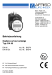
1
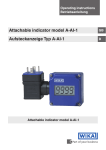
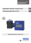
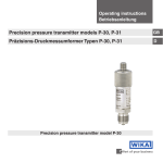
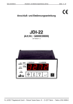
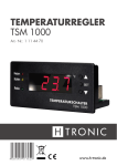
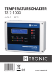
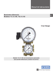
Operating instructions
Betriebsanleitung
Attachable indicator model A-AI-1
GB
Aufsteckanzeige Typ A-AI-1
D
Attachable indicator model A-AI-1
GB Operating instructions model A-AI-1
D Betriebsanleitung Typ A-AI-1
Page
3 - 22
Seite
23 - 42
Prior to starting any work, read the operating instructions!
Keep for later use!
Vor Beginn aller Arbeiten Betriebsanleitung lesen!
Zum späteren Gebrauch aufbewahren!
2
WIKA operating instructions attachable indicator model A-AI-1
2018357.05 08/2011 GB/D
© 2011 WIKA Alexander Wiegand SE & Co. KG
All rights reserved. / Alle Rechte vorbehalten.
WIKA® is a registered trademark in various countries.
WIKA® ist eine geschützte Marke in verschiedenen Ländern.
Contents
Contents
1.
2.
General information
Safety
2.1 Intended use
2.2 Personnel qualification
2.3 Special hazards
2.4 Labelling / Safety marks
3.
4.
Specifications
Design and function
4.1 Short description / Description
4.2 Scope of delivery
5.
Transport, packaging and storage
5.1 Transport
5.2 Packaging
5.3 Storage
6.
Commissioning, operation
6.1 Electrical connection
6.2 Pin assignment
6.3 Configuration of the display
7.
Maintenance and cleaning
7.1 Maintenance
7.2 Cleaning
8.
9.
Faults
Dismounting, return and disposal
2018357.05 08/2011 GB/D
9.1 Disassembly
9.2 Return
9.3 Disposal
Appendix 1: EC Declaration of conformity for model A-AI-1
4
5
5
6
7
8
10
11
11
12
12
12
12
12
13
13
13
15
18
18
18
19
20
20
20
21
22
Declarations of conformity can be found online at www.wika.com.
WIKA operating instructions attachable indicator model A-AI-1
3
GB
1. General information
1. General information
■■ The attachable indicator model A-AI-1 described in the operating
instructions has been manufactured using state-of-the-art technology. All
components are subject to stringent quality and environmental criteria
during production. Our management systems are certified to ISO 9001
and ISO 14001.
GB
■■ These operating instructions contain important information on handling the
model A-AI-1 attachable indicator. Working safely requires that all safety
instructions and work instructions are observed.
■■ Observe the relevant local accident prevention regulations and general
safety regulations for the model A-AI-1 attachable indicator's range of use.
■■ The operating instructions are part of the product and must be kept in the
immediate vicinity of the model A-AI-1 attachable indicator and readily
accessible to qualified personnel at any time.
■■ Skilled personnel must have carefully read and understood the operating
instructions prior to beginning any work.
■■ The manufacturer's liability is void in the case of any damage caused
by using the product contrary to its intended use, non-compliance with
these operating instructions, assignment of insufficiently qualified skilled
personnel or unauthorised modifications to the model A-AI-1 attachable
indicator.
■■ The general terms and conditions, contained in the sales documentation,
shall apply.
■■ Further information:
- Internet address:
- Relevant data sheet:
- Application consultant:
4
www.wika.de / www.wika.com
AC 80.07
Tel.:
(+49) 9372/132-9986
Fax:
(+49) 9372/132-8767
E-mail:
[email protected]
WIKA operating instructions attachable indicator model A-AI-1
2018357.05 08/2011 GB/D
■■ Subject to technical modifications.
1. General information / 2. Safety
Explanation of symbols
WARNING!
... indicates a potentially dangerous situation that can result in
serious injury or death, if not avoided.
CAUTION!
... indicates a potentially dangerous situation that can result in
light injuries or damage to equipment or the environment, if not
avoided.
Information
… points out useful tips, recommendations and information for
efficient and trouble-free operation.
DANGER!
...identifies hazards caused by electric power. Should the
safety instructions not be observed, there is a risk of serious or
fatal injury.
2. Safety
2018357.05 08/2011 GB/D
WARNING!
Before installation, commissioning and operation, ensure
that the appropriate instrument has been selected in terms of
measuring range, design and specific measuring conditions.
Non-observance can result in serious injury and/or damage to
the equipment.
Further important safety instructions can be found in the
individual chapters of these operating instructions.
2.1 Intended use
The model A-AI-1 attachable indicator is suitable for insertion between a
transmitter and the corresponding output connector (angular connector).
WIKA operating instructions attachable indicator model A-AI-1
5
GB
2. Safety
The attachable indicator has been designed and built solely for the intended
use described here, and may only be used accordingly.
Handle electronic precision measuring instruments with the required care
(protect from humidity, impacts, strong magnetic fields, static electricity and
extreme temperatures, do not insert any objects into the instrument or its
openings). Plugs and sockets must be protected from contamination.
If the attachable indicator is transported from a cold into a warm environment, the formation of condensation may result in instrument malfunction.
The manufacturer shall not be liable for claims of any type based on operation contrary to the intended use.
2.2 Personnel qualification
WARNING!
Risk of injury should qualification be insufficient!
Improper handling can result in considerable injury and
damage to equipment.
■■ The activities described in these operating instructions may
only be carried out by skilled personnel who have the qualifications described below.
■■ Keep unqualified personnel away from hazardous areas.
Skilled electrical personnel
Skilled electrical personnel are understood to be personnel who, based on
their technical training, know-how and experience as well as their knowledge
of country-specific regulations, current standards and directives, are capable
of carrying out work on electrical systems and independently recognising
and avoiding potential hazards.
6
WIKA operating instructions attachable indicator model A-AI-1
2018357.05 08/2011 GB/D
GB
The technical specifications contained in these operating instructions must
be observed. Improper handling or operation of the attachable indicator
outside of its technical specifications requires the instrument to be taken
out of service immediately and inspected by an authorised WIKA service
engineer.
2. Safety
The skilled electrical personnel have been specifically trained for the work
environment they are working in and know the relevant standards and regulations.
The skilled electrical personnel must comply with current legal accident
prevention regulations.
2.3 Special hazards
DANGER!
Danger of death caused by electric current
Upon contact with live parts, there is a direct danger of death.
■■ Electrical instruments may only be installed and connected
by skilled electrical personnel.
WARNING!
Do not use this instrument in safety or Emergency Stop
devices. Incorrect use of the instrument can result in injury or
material damage.
2018357.05 08/2011 GB/D
This instrument has been designed and tested in accordance
with the relevant safety regulations for electronic measuring
instruments.
The trouble-free operation and reliability of the instrument can
only be guaranteed if the general safety measures and the
instrument-specific safety instructions given in this manual are
followed.
WARNING!
■■ Observe the working conditions in accordance with chapter
"3. Specifications".
■■ Prior to opening the instrument, disconnect it from the power
supply. Take care that, in fitting the instrument and connections, all components are protected against direct contact.
■■ Observe standard regulations and safety rules for electrical,
low-power and high-power systems, especially any countryspecific safety regulations (for example VDE 0100).
WIKA operating instructions attachable indicator model A-AI-1
7
GB
2. Safety
WARNING!
■■ Design the wiring particularly carefully when connecting
to other devices (e.g. a PC). Under certain circumstances,
internal connections in third-party devices (e.g. GND
connected to the safety earth) can lead to impermissible
voltages.
■■ If the connected cable is longer than 30 metres, or it runs
outside the building, an additional and suitable overvoltage
protection should be provided.
GB
The safety of the operator may be endangered if, for example:
■■ there is visible damage to the instrument.
■■ the instrument is not working as specified.
■■ the instrument has been stored under unsuitable conditions for an
extended period of time.
If there is any doubt, please return the instrument to the manufacturer for
repair or maintenance.
2.4 Labelling / Safety marks
2.4.1 Product label
Eingang/Input
: 4 … 20 mA
2-Leiter/-wire
Spannungsabfall/Voltage Drop: DC 2 V
Bestell-/Order Code : A-AI-1-HZ-Z
Bestell-Nr./Order No. : 7082534
Serien-Nr./Serial No. : 1234567
YYYY-MM
Input current
Voltage supply
Order code
Order no.
Serial no.
Date of manufacture
WIKA Alexander Wiegand SE & Co. KG
D-63911 Klingenberg
Made in Germany
8
WIKA operating instructions attachable indicator model A-AI-1
2018357.05 08/2011 GB/D
Digital-Anzeige/-Indicator A-AI-1
For an explanation of
symbols, see next page
2. Safety / 3. Specifications
2.4.2 Explanation of symbols
Before mounting and commissioning the instrument, ensure
you read the operating instructions!
CE, Communauté Européenne
Instruments bearing this mark comply with the relevant
European directives.
GB
3. Specifications
Attachable indicator
Display
Principle
Indication range
Accuracy
Measuring rate
Voltage supply
Electrical connection
Power supply
Voltage drop
Permitted current carrying
capacity
7-segment LCD, 4-digit, character size 10 mm
-1999 ... 9999
± 0.2 % of the measuring span ± 1 digit
5 measurements/sec
To transmitters with 4 ... 20 mA output and
angular connector to DIN 43650.
Not required, since the attachable indicator is
powered by the 4 ... 20 mA loop
approx. DC 2 V
max. 40 mA
2018357.05 08/2011 GB/D
Case
Material
Ingress protection
Dimensions
Weight
ABS, front window from polycarbonate
IP 65 per EN 60529 / IEC 529
48.5 x 48.5 mm
approx. 80 g
WIKA operating instructions attachable indicator model A-AI-1
9
3. Specifications
Permissible ambient conditions
CE conformity
EMC directive
0 ... 50 °C
-20 ... +70 °C
< 80 % r.h. non-condensing
0.1 % / 10 K
2004/108/EC, EN 61326 emission (group 1,
class B) and interference immunity (industrial
application)
For further specifications see WIKA data sheet AC 80.07 and the order documentation.
Dimensions in mm
2018357.05 08/2011 GB/D
GB
Operating temperature
Storage temperature
Relative humidity
Temperature effect on the
indication
10
WIKA operating instructions attachable indicator model A-AI-1
4. Design and function
4. Design and function
4.1 Description
The model A-AI-1 attachable indicator is a general-purpose, microprocessorcontrolled indicator for standard 4 ... 20 mA signals. It does not require its
own power supply, but rather, it is powered directly from the measuring
current. The display of the measured value is made on a 4-digit LCD display
with a maximum indication range of -1999 ... 9999 digits.
The A-AI-1 has been designed for the connection of any transmitter
(with 4 ... 20 mA output). The matching of the indicator range to the transmitter is made without external aids through the direct input of the upper and
lower measuring range limits and the decimal point. The parameters and limit
values are entered using three keys, accessible on removal of the cover. All
programmable parameters are saved in an EEProm and are retained in the
event of a loss of power (for a minimum of 10 years).
The attachable indicator has its own integrated self-diagnostics, which
continuously checks that the key components of the instrument are working
properly. The integrated self-diagnostics, as well as the reporting of an overrange or under-range condition, ensure high operational safety.
2018357.05 08/2011 GB/D
The attachable indicator is delivered tested and fully calibrated. It is therefore
ready for operation, though it must first be configured for the particular application. See chapter "6.3 Configuration of the display".
4.2 Scope of delivery
The scope of delivery includes the following components:
■■ Attachable indicator
■■ 2 mounting screws (68 mm and 75 mm)
■■ Sealing
■■ Operating instructions
Cross-check scope of delivery with the delivery note.
WIKA operating instructions attachable indicator model A-AI-1
11
GB
5. Transport, packaging and storage
5. Transport, packaging and storage
5.2 Packaging
Do not remove packaging until just before mounting.
Keep the packaging as it will provide optimum protection during transport
(e.g. change in installation site, sending for repair).
5.3 Storage
Permissible conditions at the place of storage:
■■ Storage temperature: -20 ... +70 °C
■■ Humidity: 0 ... 80 % relative humidity (non condensing)
Avoid exposure to the following factors:
■■ Direct sunlight or proximity to hot objects
■■ Mechanical vibration, mechanical shock (putting it down hard)
■■ Soot, vapour, dust and corrosive gases
■■ Potentially explosive environments, flammable atmospheres
Store the attachable indicator in its original packaging in a location that fulfils
the conditions listed above. If the original packaging is not available, pack
and store the attachable indicator as described below:
1. Wrap the attachable indicator in an antistatic plastic film.
2. Place the attachable indicator, along with shock-absorbent material, in the
packaging.
3. If stored for a prolonged period of time (more than 30 days), place a bag
containing a desiccant inside the packaging.
WARNING!
Before storing the attachable indicator (following operation),
remove any residual media. This is of particular importance if
the medium is hazardous to health, e.g. caustic, toxic, carcinogenic, radioactive, etc.
12
WIKA operating instructions attachable indicator model A-AI-1
2018357.05 08/2011 GB/D
GB
5.1 Transport
Check the attachable indicator for any damage that may have been caused
during transportation.
Obvious damage must be reported immediately.
6. Commissioning, operation
6. Commissioning, operation
6.1 Electrical connection
The connection of the attachable indicator is made via simply plugging it
between an existing transmitter and connector using a specific adapter
design for connectors to DIN 43650.
No separate power supply is needed since the instrument is powered directly
from the measuring current.
The connection and commissioning should only be carried out
by skilled, qualified personnel. An incorrect connection could
damage the indicator.
CAUTION!
Note the maximum permissible input current of 40 mA!
6.2 Pin assignment
The assignment of the angular connector is designed for the most commonly-used configuration for the respective input signal. Since this assignment
is not standardised, it can happen that the assignment for the connected
transmitter does not match the assignment of the attachable indicator.
Standard assignment for the model A-AI-1 angular connector
Contact no.
Wiring colour Pin
Female connector
1
grey
Display +
Display -
3
--
n.c.
n.c.
2
2018357.05 08/2011 GB/D
4
red
--
connected
n.c.
n.c.
n.c. = not connected
WIKA operating instructions attachable indicator model A-AI-1
13
GB
6. Commissioning, operation
In the angular connector, the pin contact 2 is directly connected (1:1) with
the female contact. Between pin contact 1 (+) and female contact 1 (-) is the
A-AI-1.
Pin contacts
GB
Female connector
If the transmitter to be connected does not have the negative power terminal
on contact 2 and the positive power terminal is not on contact 1, then
the assignment of the A-AI-1 angular connector and the external angular
connector must be matched accordingly. To do this, open the A-AI-1 angular
connector and exchange the wires from contact 1 and contact 2, so that
these match the connection of the transmitter to be attached.
General information on changing the angular connector assignment
Lift out the coupling assembly using a screwdriver in the recess on the side.
Change the assignment in line with the instructions for the relevant input
signal.
Then snap the coupling assembly back into the cover. There are 4 different
output orientations to choose from - each at 90° to each other. Attach the
angular connector and screw the connector together using the long bolt
delivered with the unit (don't forget the seals).
14
WIKA operating instructions attachable indicator model A-AI-1
2018357.05 08/2011 GB/D
Now wire both contacts in the angular connector accordingly.
6. Commissioning, operation
6.3 Configuration of the display
To configure the instrument, the cover must first be carefully removed, in
order that the keys behind it can be reached. To do this, the four screws on
the corners of the case must be removed.
GB
Operating keys
Key 1:
Calling menu options and saving settings
Key 2:
Increasing the parameter values
Key 3:
Decreasing the parameter values
2018357.05 08/2011 GB/D
Key 1
Key 2
Key 3
Once the cover has been removed, to configure the instrument continue as
follows:
■■ To access the menu, while the actual value is displayed, press key 2 for 2
seconds until "dP" appears in the display.
■■ To set the parameter values, press keys 2 and 3.
■■ To save the set value, press key 1. The parameter name will then appear in
the display once more.
■■ To get to the next parameter to change, press key 1. The name of the
parameter will appear in the display.
If, during input, no key is pressed for 60 seconds, the configuration of the instrument will be interrupted. Previously-saved
values will not be lost.
WIKA operating instructions attachable indicator model A-AI-1
15
6. Commissioning, operation
Parameters of the A-AI-1 attachable indicator
Parameters Values
GB
dP
di.Lo
di.Hi
Li
FiLt
16
Keys 2 and 3
Description
Position of the decimal point (decimal point)
---Max. indication range: -1999 … 9999
---.Max. indication range: -199.9 … 999.9
--.-Max. indication range: -19.99 … 99.99
-.--Max. indication range: -1.999 … 9.999
Lower indication range limit (display low)
-1999 ... 9999 This value will be displayed when the input signal
= 4 mA
Upper indication range limit (display high)
-1999 ... 9999 This value will be displayed when the input signal
= 20 mA
Measuring range limit (limit)
oFF
deactivated
Exceeding the measuring range limits is permitted
up to the measuring limit (see note)
on.Er
active, (error display):
The measuring range is limited exactly to the input
signal. When this exceeds or drops below it, a
corresponding error message is displayed.
on.rG
active, (display measuring range limits):
The measuring range is limited exactly to the input
signal. When this exceeds or drops below it, the
indication range limit is displayed. (e.g. for a humidity of 0 ... 100 % r.H: by dropping below the limit 0 is
displayed, and by exceeding it 100 is displayed.
When the measuring limits are exceeded (at either end), independently of the limit settings, the corresponding error message
appears ("Err.1", below, or "Err.2", above). The measuring limits
are between approx. 3.7 and 20.8 mA.
Filter (filter)
oFF
0.1 ... 2.0
Filter deactivated
Activate the filter in order to prevent the display
from 'jumping' with every small fluctuation and to
suppress single spikes. The larger the number, the
stronger the filtering.
Warning: this causes a delay in the switching
response!
WIKA operating instructions attachable indicator model A-AI-1
2018357.05 08/2011 GB/D
Key 1
6. Commissioning, operation
Offset and slope correction
The offset and slope correction is used to compensate for sensor tolerances
and for the fine adjustment of deviations of the transmitter or signal transducer.
To set the offset and slope correction, carry out the following:
■■ While the actual value is being displayed, press key 3 for 2 seconds, until
"oFFS" appears in the display.
■■ To set the parameter values, press keys 2 and 3.
■■ To save the set value, press key 1. The parameter name will then appear in
the display once more.
■■ To get to the next parameter to change, press key 1. The name of the
parameter will appear in the display.
Parameters Values
Key 1
oFFS
ScAL
Keys 2 and 3
Description
Zero offset (offset)
-5.00 … 5.00 The input of the offset is made in digits. The set
offset value is subtracted from the measured value.
Slope (scale)
-5.00 … 5.00 The input of the slope correction factor is made
in %. The displayed value is calculated as per the
following equation:
Display = (measured value - Offset - di.Lo) * (1 +
slope correction [% / 100] ) + di.Lo
2018357.05 08/2011 GB/D
Example for offset and slope correction
Connection of a pressure transmitter
The instrument display without offset and slope correction is as follows:
at 0 bar = 0.08, at 20 bar = 20.02
From this is calculated:
Zero point:
0.08
Slope:
20.02 – 0.08 = 19.94
Deviation:
0.06 = set - slope - actual slope = 20.00 – 19.94
Therefore the following should be set:
Offset =
0.08 = zero error
Scale =
0.30 = deviation / actual slope = 0.06 /19.94 = 0.0030 = 0.30 %
WIKA operating instructions attachable indicator model A-AI-1
17
GB
6. Commissioning, operation / 7. Maintenance and cleaning
Min/Max value memory
The instrument has a Min/Max value memory. In this are stored the lowest
and the highest diplayed values. The Min/Max value memory is a volatile
memory, meaning the stored values are lost when the power is interrupted.
To recall Min
value:
To recall Max
value:
Key
Display
Press key 2 briefly
"Hi" will be displayed briefly and then
for approx. 2 s the Max value will be
shown.
Press key 3 briefly
To delete the
Press keys 2 and
Min/Max values: 3 simultaneously
for 2 s.
"Lo" will be displayed briefly and then
for approx. 2 s the Min value will be
shown.
"CLr" will briefly be shown in the
display, the Min/Max value will be reset
to the current display value.
7. Maintenance and cleaning
7.1 Maintenance
This attachable indicator is maintenance-free.
Repairs must only be carried out by the manufacturer.
7.2 Cleaning
CAUTION!
■■ Prior to cleaning, disconnect the attachable indicator from
the mains.
■■ Clean the attachable indicator with a moist cloth.
■■ Electrical connections must not come into contact with
moisture.
For information on returning the attachable indicator see
chapter "9.2 Return".
18
WIKA operating instructions attachable indicator model A-AI-1
2018357.05 08/2011 GB/D
GB
8. Faults
8. Faults
If the instrument detects any fault conditions, the corresponding error code
will be displayed.
The following error codes are defined:
2018357.05 08/2011 GB/D
Error
Causes
Measures
Err.1
Measuring range
exceeded
■■ Input signal too high
■■ Faulty connection
■■ The error message will reset
Err.2
Measured value
below allowable
range
■■ Input signal too low, or
■■ The error message will reset
Err.3
Indication range
exceeded
■■ Scaling incorrect
■■ The error message will be
Err.4
Under the indication range
■■ Scaling incorrect
■■ The error message will reset
Err.7
System error
■■ Permissible operating
Err.11
Value could not be
calculated
■■ Scaling incorrect
negative
■■ Current less than 4 mA
■■ Sensor burnout
itself once the input signal is
once more within the permissible limits.
■■ Check the transmitter and
the instrument configuration
(e.g. input signal).
itself once the input signal is
once more within the permissible limits.
■■ Check the transmitter and
the instrument configuration
(e.g. input signal).
reset once the display value
is once more < 9999.
itself once the display value
is once more within the
permissible limits.
■■ Abide by the operating
temperature too high or
temperature limits
■■ Replace instrument
too low.
■■ Instrument faulty
■■ Check the setting and the
input signal
WIKA operating instructions attachable indicator model A-AI-1
19
GB
8. Faults / 9. Dismounting, return and disposal
CAUTION!
If faults cannot be eliminated by means of the measures listed
above, the attachable indicator must be shut down immediately, and it must be ensured that signal is no longer present,
and it must be prevented from being inadvertently put back into
service.
In this case, contact the manufacturer.
If a return is needed, follow the instructions given in chapter
"9.2 Returns".
GB
9. Dismounting, return and disposal
WARNING!
Residual media in dismounted instruments can result in a risk
to persons, the environment and equipment.
Take sufficient precautionary measures.
9.1 Dismounting
First disconnect the power supply, then loosen the angle screw, with which
the angular connector, attachable indicator and transmitter are connected.
Remove the plug and the attachable indicator. Then replace the angular
connector onto the transmitter and secure it. For this, use the screw originally
supplied with the transmitter, it is shorter.
WARNING!
Strictly observe the following when shipping the attachable indicator:
All instruments delivered to WIKA must be free from any kind of
hazardous substances (acids, leachate, solutions, etc.).
When returning the instrument, use the original packaging or a suitable
transport package.
20
WIKA operating instructions attachable indicator model A-AI-1
2018357.05 08/2011 GB/D
9.2 Returns
9. Dismounting, return and disposal
To avoid damage:
1. Wrap the attachable indicator in an antistatic plastic film.
2. Place the attachable indicator, along with shock-absorbent material, in
the packaging. Place shock-absorbent material evenly on all sides of the
shipping box.
3. If possible, place a bag containing a desiccant inside the packaging.
4. Label the shipment as transport of a highly-sensitive measuring instrument.
Enclose the completed returns form with the instrument.
The return form is available on the internet:
www.wika.com / Service / Returns
2018357.05 08/2011 GB/D
9.3 Disposal
Incorrect disposal can put the environment at risk.
Dispose of instrument components and packaging materials in an environmentally compatible way and in accordance with the country-specific waste
disposal regulations.
WIKA operating instructions attachable indicator model A-AI-1
21
GB
Appendix 1: EC Declaration of conformity for model A-AI-1
2018357.05 08/2011 GB/D
GB
22
WIKA operating instructions attachable indicator model A-AI-1
Inhalt
Inhalt
1.
2.
Allgemeines
Sicherheit
2.1 Bestimmungsgemäße Verwendung
2.2 Personalqualifikation
2.3 Besondere Gefahren
2.4 Beschilderung / Sicherheitskennzeichnungen
3.
4.
Technische Daten
Aufbau und Funktion
4.1 Kurzbeschreibung / Beschreibung
4.2 Lieferumfang
5.
Transport, Verpackung und Lagerung
5.1 Transport
5.2 Verpackung
5.3 Lagerung
6.
Inbetriebnahme, Betrieb
6.1 Elektrischer Anschluss
6.2 Anschlussbelegung
6.3 Konfiguration der Anzeige
7.
Wartung und Reinigung
7.1 Wartung
7.2 Reinigung
8.
9.
Störungen
Demontage, Rücksendung und Entsorgung
2018357.05 08/2011 GB/D
9.1 Demontage
9.2 Rücksendung
9.3 Entsorgung
Anlage 1: EG-Konformitätserklärung Typ A-AI-1
24
25
25
26
27
28
30
31
31
32
32
32
32
32
33
33
33
35
38
38
38
39
40
40
40
41
42
Konformitätserklärungen finden Sie online unter www.wika.de.
WIKA Betriebsanleitung Aufsteckanzeige Typ A-AI-1
23
D
1. Allgemeines
1. Allgemeines
■■ Die in der Betriebsanleitung beschriebene Aufsteckanzeige Typ A-AI-1
wird nach den neuesten Erkenntnissen gefertigt.
Alle Komponenten unterliegen während der Fertigung strengen Qualitätsund Umweltkriterien. Unsere Managementsysteme sind nach ISO 9001
und ISO 14001 zertifiziert.
■■ Diese Betriebsanleitung gibt wichtige Hinweise zum Umgang mit der
Aufsteckanzeige Typ A-AI-1. Voraussetzung für sicheres Arbeiten ist die
Einhaltung aller angegebenen Sicherheitshinweise und Handlungsanweisungen.
■■ Die für den Einsatzbereich der Aufsteckanzeige Typ A-AI-1 geltenden
örtlichen Unfallverhütungsvorschriften und allgemeinen Sicherheitsbestimmungen einhalten.
■■ Die Betriebsanleitung ist Produktbestandteil und muss in unmittelbarer
Nähe der Aufsteckanzeige Typ A-AI-1 für das Fachpersonal jederzeit
zugänglich aufbewahrt werden.
■■ Das Fachpersonal muss die Betriebsanleitung vor Beginn aller Arbeiten
sorgfältig durchgelesen und verstanden haben.
■■ Die Haftung des Herstellers erlischt bei Schäden durch bestimmungs-
widrige Verwendung, Nichtbeachten dieser Betriebsanleitung, Einsatz
ungenügend qualifizierten Fachpersonals sowie eigenmächtiger Veränderung an der Aufsteckanzeige Typ A-AI-1.
■■ Es gelten die allgemeinen Geschäftsbedingungen in den Verkaufsunter-
lagen.
■■ Technische Änderungen vorbehalten.
■■ Weitere Informationen:
- Internet-Adresse:
- zugehöriges Datenblatt:
- Anwendungsberater:
24
www.wika.de / www.wika.com
AC 80.07
Tel.:
(+49) 9372/132-9986
Fax:
(+49) 9372/132-8767
E-Mail:
[email protected]
WIKA Betriebsanleitung Aufsteckanzeige Typ A-AI-1
2018357.05 08/2011 GB/D
D
1. Allgemeines / 2. Sicherheit
Symbolerklärung
WARNUNG!
… weist auf eine möglicherweise gefährliche Situation hin, die
zum Tod oder zu schweren Verletzungen führen kann, wenn sie
nicht gemieden wird.
VORSICHT!
… weist auf eine möglicherweise gefährliche Situation hin, die
zu geringfügigen oder leichten Verletzungen bzw. Sach- und
Umweltschäden führen kann, wenn sie nicht gemieden wird.
Information
… hebt nützliche Tipps und Empfehlungen sowie Informationen für einen effizienten und störungsfreien Betrieb hervor.
GEFAHR!
…kennzeichnet Gefährdungen durch elektrischen Strom. Bei
Nichtbeachtung der Sicherheitshinweise besteht die Gefahr
schwerer oder tödlicher Verletzungen.
2. Sicherheit
2018357.05 08/2011 GB/D
WARNUNG!
Vor Montage, Inbetriebnahme und Betrieb sicherstellen, dass
das richtige Gerät hinsichtlich Messbereich, Ausführung und
spezifischen Messbedingungen ausgewählt wurde.
Bei Nichtbeachten können schwere Körperverletzungen und/
oder Sachschäden auftreten.
Weitere wichtige Sicherheitshinweise befinden sich in den
einzelnen Kapiteln dieser Betriebsanleitung.
2.1 Bestimmungsgemäße Verwendung
Die Aufsteckanzeige Typ A-AI-1 ist zum Zwischenstecken zwischen einem
Transmitter und dem dazugehörigen Ausgangsstecker (Winkelstecker)
geeignet.
WIKA Betriebsanleitung Aufsteckanzeige Typ A-AI-1
25
D
2. Sicherheit
Die Aufsteckanzeige ist ausschließlich für den hier beschriebenen bestimmungsgemäßen Verwendungszweck konzipiert und konstruiert und darf nur
dementsprechend verwendet werden.
Elektronische Präzisionsmessgeräte mit erforderlicher Sorgfalt behandeln (vor Nässe, Stößen, starken Magnetfeldern, statische Elektrizität und
extremen Temperaturen schützen, keine Gegenstände in das Gerät bzw.
Öffnungen einführen). Stecker und Buchsen vor Verschmutzung schützen.
Wird die Aufsteckanzeige von einer kalten in eine warme Umgebung transportiert, so kann durch Kondensatbildung eine Störung der Gerätefunktion
eintreten. Vor einer erneuten Inbetriebnahme die Angleichung der Gerätetemperatur an die Raumtemperatur abwarten.
Ansprüche jeglicher Art aufgrund von nicht bestimmungsgemäßer Verwendung sind ausgeschlossen.
2.2 Personalqualifikation
WARNUNG!
Verletzungsgefahr bei unzureichender Qualifikation!
Unsachgemäßer Umgang kann zu erheblichen Personen- und
Sachschäden führen.
■■ Die in dieser Betriebsanleitung beschriebenen Tätigkeiten
nur durch Fachpersonal nachfolgend beschriebener Qualifikation durchführen lassen.
■■ Unqualifiziertes Personal von den Gefahrenbereichen
fernhalten.
Elektrofachpersonal
Das Elektrofachpersonal ist aufgrund seiner fachlichen Ausbildung, Kenntnisse und Erfahrungen sowie Kenntnis der landesspezifischen Vorschriften,
26
WIKA Betriebsanleitung Aufsteckanzeige Typ A-AI-1
2018357.05 08/2011 GB/D
D
Die technischen Spezifikationen in dieser Betriebsanleitung sind einzuhalten.
Eine unsachgemäße Handhabung oder ein Betreiben der Aufsteckanzeige
außerhalb der technischen Spezifikationen macht die sofortige Stilllegung
und Überprüfung durch einen autorisierten WIKA-Servicemitarbeiter erforderlich.
2. Sicherheit
geltenden Normen und Richtlinien in der Lage, Arbeiten an elektrischen
Anlagen auszuführen und mögliche Gefahren selbstständig zu erkennen und
zu vermeiden.
Das Elektrofachpersonal ist speziell für das Arbeitsumfeld, in dem es tätig ist,
ausgebildet und kennt die relevanten Normen und Bestimmungen.
Das Elektrofachpersonal muss die Bestimmungen der geltenden gesetzlichen Vorschriften zur Unfallverhütung erfüllen.
D
2.3 Besondere Gefahren
GEFAHR!
Lebensgefahr durch elektrischen Strom
Bei Berührung mit spannungsführenden Teilen besteht unmittelbare Lebensgefahr.
■■ Einbau und Montage des elektrischen Gerätes dürfen nur
durch das Elektrofachpersonal erfolgen.
WARNUNG!
Dieses Gerät nicht in Sicherheits- oder in Not-Aus-Einrichtungen benutzen. Fehlerhafte Anwendungen des Gerätes können
zu Verletzungen oder materiellen Schäden führen.
2018357.05 08/2011 GB/D
Dieses Gerät ist gemäß den Sicherheitsbestimmungen für
elektronische Messgeräte gebaut und geprüft.
Die einwandfreie Funktion und Betriebssicherheit des Gerätes
kann nur dann gewährleistet werden, wenn bei der Benutzung
die allgemein üblichen Sicherheitsvorkehrungen sowie die
gerätespezifischen Sicherheitshinweise in dieser Bedienungsanleitung beachtet werden.
WARNUNG!
■■ Betriebsparameter gemäß Kapitel "3. Technische Daten"
beachten.
■■ Das Gerät vor dem Öffnen von der Versorgungsspannung trennen. Darauf achten, dass bei der Montage von
Gerät und Anschlüssen alle Teile gegen direktes Berühren
geschützt sind.
WIKA Betriebsanleitung Aufsteckanzeige Typ A-AI-1
27
2. Sicherheit
WARNUNG!
■■ Die üblichen Vorschriften und Sicherheitsbestimmungen
für Elektro-, Schwach- und Starkstromanlagen, insbesondere die landesüblichen Sicherheitsbestimmungen (z. B.
VDE 0100) beachten.
■■ Die Beschaltung besonders sorgfältig beim Anschluss an
andere Geräte (z. B. PC) konzipieren. Unter Umständen
können interne Verbindungen in Fremdgeräten (z. B. Verbindung GND mit Schutzerde) zu nicht erlaubten Spannungspotentialen führen.
■■ Wenn die angeschlossene Leitung länger als 30 Meter ist
oder das Gebäude verlässt, muss ein zusätzlicher geeigneter Überspannungsschutz verwendet werden.
D
Die Sicherheit des Benutzers kann durch das Gerät beeinträchtigt sein, wenn
es zum Beispiel:
■■ sichtbare Schäden aufweist.
■■ nicht mehr wie vorgeschrieben arbeitet.
■■ längere Zeit unter ungeeigneten Bedingungen gelagert wurde.
In Zweifelsfällen das Gerät grundsätzlich an den Hersteller zur Reparatur
bzw. Wartung einschicken.
2.4 Beschilderung / Sicherheitskennzeichnungen
2.4.1 Typenschild
Eingang/Input
: 4 … 20 mA
2-Leiter/-wire
Spannungsabfall/Voltage Drop: DC 2 V
Bestell-/Order Code : A-AI-1-HZ-Z
Bestell-Nr./Order No. : 7082534
Serien-Nr./Serial No. : 1234567
YYYY-MM
Symbolerklärung siehe
nächste Seite
Eingangsstrom
Spannungsversorgung
Bestell-Code
Bestell-Nr.
Serien-Nr.
Herstellungsdatum
WIKA Alexander Wiegand SE & Co. KG
D-63911 Klingenberg
Made in Germany
28
WIKA Betriebsanleitung Aufsteckanzeige Typ A-AI-1
2018357.05 08/2011 GB/D
Digital-Anzeige/-Indicator A-AI-1
2. Sicherheit / 3. Technische Daten
2.4.2 Symbolerklärung
Vor Montage und Inbetriebnahme des Gerätes unbedingt die
Betriebsanleitung lesen!
CE, Communauté Européenne
Geräte mit dieser Kennzeichnung stimmen überein mit den
zutreffenden europäischen Richtlinien.
D
3. Technische Daten
Aufsteckanzeige
Anzeige
Prinzip
Display-Anzeigebereich
Genauigkeit
Messrate
Spannungsversorgung
Elektrischer Anschluss
Hilfsenergie
Spannungsabfall
Zulässige Strombelastbarkeit
7-Segment-LCD, 4-stellig, Ziffernhöhe 10 mm
-1999 ... 9999
± 0,2 % der Messspanne ± 1 Digit
5 Messungen/sek
An Messumformer mit Ausgang 4 ... 20 mA und
Winkelstecker nach DIN 43650.
Nicht erforderlich, da die Aufsteckanzeige aus
der 4 ... 20 mA-Schleife versorgt wird.
ca. DC 2 V
max. 40 mA
2018357.05 08/2011 GB/D
Gehäuse
Material
Schutzart
Abmessungen
Gewicht
ABS, Frontscheibe aus Polycarbonat
IP 65 nach EN 60529 / IEC 529
48,5 x 48,5 mm
ca. 80 g
WIKA Betriebsanleitung Aufsteckanzeige Typ A-AI-1
29
3. Technische Daten
Zulässige Umgebungsbedingungen
Betriebstemperatur
Lagertemperatur
Relative Luftfeuchte
Temperatureinfluss auf die
Anzeige
D CE-Konformität
EMV-Richtlinie
0 ... 50 °C
-20 ... +70 °C
< 80 % r. F. nicht kondensierend
0,1 % / 10 K
2004/108/EG, EN 61326 Emission (Gruppe
1, Klasse B) und Störfestigkeit (industrieller
Bereich)
Weitere technische Daten siehe WIKA Datenblatt AC 80.07 und Bestellunterlagen.
2018357.05 08/2011 GB/D
Abmessungen in mm
30
WIKA Betriebsanleitung Aufsteckanzeige Typ A-AI-1
4. Aufbau und Funktion
4. Aufbau und Funktion
4.1 Beschreibung
Die Aufsteckanzeige Typ A-AI-1 ist ein universell einsetzbares, mikroprozessorgesteuertes Anzeigegerät für 4 ... 20 mA Normsignale. Sie benötigt keine
eigene Hilfsspannung sondern versorgt sich direkt aus dem Messstrom.
Die Anzeige des Messwertes erfolgt auf einem 4-stelligen LCD-Display mit
einem maximalen Display-Anzeigebereich von -1999 ... 9999 Digit.
Die A-AI-1 ist für den Anschluss beliebiger Messumformer (mit 4 ... 20 mA
Ausgang) ausgelegt. Die Bereichsanpassung des Anzeigegerätes an
den Transmitter erfolgt ohne externe Hilfsmittel durch direkte Eingabe der
oberen und unteren Messbereichsgrenze und der Dezimalpunktposition. Die
Parameter und Grenzwerte werden über drei, nach Abnahme des Deckels,
zugängliche Tasten eingegeben. Alle programmierbaren Parameter werden
in einem EEProm gesichert und bleiben bei Stromausfall für mindestens
10 Jahre erhalten.
Die Aufsteckanzeige hat eine integrierte Eigendiagnose, die ständig
wesentliche Teile des Gerätes auf einwandfreie Funktion kontrolliert. Diese
Eigendiagnose, sowie die Überwachung des Messwertaufnehmers auf
Bereichsüber- bzw. Bereichsunterschreitung sind der Garant für eine hohe
Betriebssicherheit.
2018357.05 08/2011 GB/D
Die Aufsteckanzeige wird geprüft und komplett kalibriert geliefert. Damit sie
betriebsbereit ist, muss sie aber noch für die jeweilige Anwendung konfiguriert werden. Siehe Kapitel "6.3 Konfiguration der Anzeige".
4.2 Lieferumfang
Der Lieferumfang umfasst folgende Teile:
■■ Aufsteckanzeige
■■ 2 Befestigungsschrauben (68 mm und 75 mm)
■■ Dichtung
■■ Betriebsanleitung
Lieferumfang mit dem Lieferschein abgleichen.
WIKA Betriebsanleitung Aufsteckanzeige Typ A-AI-1
31
D
5. Transport, Verpackung und Lagerung
5. Transport, Verpackung und Lagerung
5.1 Transport
Aufsteckanzeige auf eventuell vorhandene Transportschäden untersuchen.
Offensichtliche Schäden unverzüglich mitteilen.
5.3 Lagerung
Zulässige Bedingungen am Lagerort:
■■ Lagertemperatur: -20 ... +70 °C
■■ Feuchtigkeit: 0 ... 80 % relative Feuchte (keine Betauung)
Folgende Einflüsse vermeiden:
■■ Direktes Sonnenlicht oder Nähe zu heißen Gegenständen
■■ Mechanische Vibration, mechanischer Schock (hartes Aufstellen)
■■ Ruß, Dampf, Staub und korrosive Gase
■■ Explosionsgefährdete Umgebung, entzündliche Atmosphären
Die Aufsteckanzeige in der Originalverpackung an einem Ort, der die oben
gelisteten Bedingungen erfüllt, lagern. Wenn die Originalverpackung nicht
vorhanden ist, dann die Aufsteckanzeige wie folgt verpacken und lagern:
1. Die Aufsteckanzeige in eine antistatische Plastikfolie einhüllen.
2. Die Aufsteckanzeige mit dem Dämmmaterial in der Verpackung platzieren.
3. Bei längerer Einlagerung (mehr als 30 Tage) einen Beutel mit Trocknungsmittel der Verpackung beilegen.
WARNUNG!
Vor der Einlagerung der Aufsteckanzeige (nach Betrieb) alle
anhaftenden Messstoffreste entfernen. Dies ist besonders
wichtig, wenn der Messstoff gesundheitsgefährdend ist, wie z.
B. ätzend, giftig, krebserregend, radioaktiv, usw.
32
WIKA Betriebsanleitung Aufsteckanzeige Typ A-AI-1
2018357.05 08/2011 GB/D
D
5.2 Verpackung
Verpackung erst unmittelbar vor der Montage entfernen.
Die Verpackung aufbewahren, denn diese bietet bei einem Transport einen
optimalen Schutz (z. B. wechselnder Einbauort, Reparatursendung).
6. Inbetriebnahme, Betrieb
6. Inbetriebnahme, Betrieb
6.1 Elektrischer Anschluss
Der Anschluss der Aufsteckanzeige erfolgt durch einfaches Dazwischenstecken an einen vorhandenen Transmitter mit Hilfe einer Spezial-Adapterkonstruktion für Würfelstecker nach DIN 43650.
Es ist keine separate Versorgungsspannung notwendig, da sich das Gerät
direkt aus dem Messstrom versorgt.
Der Anschluss bzw. die Inbetriebnahme darf nur durch fachlich
qualifizierte Personen erfolgen. Bei falschem Anschluss kann
das Anzeigegerät zerstört werden!
VORSICHT!
Unbedingt den max. zulässigen Eingangsstrom von 40 mA
beachten!
6.2 Anschlussbelegung
Die Winkelsteckerbelegung ist auf die gebräuchlichste Belegung des jeweiligen Eingangssignals ausgelegt. Da diese Belegung jedoch nicht genormt ist,
kann es vorkommen, dass die Belegung des anzuschließenden Transmitters
nicht mit der Belegung der Aufsteckanzeige übereinstimmt.
Standard-Belegung des Winkelsteckers Typ A-AI-1
Kontakt-Nr.
Adernfarbe
Stift
Buchse
1
grau
Anzeige +
Anzeige -
--
n.c.
n.c.
2
rot
4
--
2018357.05 08/2011 GB/D
3
verbunden
n.c.
n.c.
n.c. = not connected
WIKA Betriebsanleitung Aufsteckanzeige Typ A-AI-1
33
D
6. Inbetriebnahme, Betrieb
Im Winkelstecker ist der Stiftkontakt 2 direkt 1:1 mit der Buchse verbunden.
Zwischen Stiftkontakt 1 (+) und Buchsenkontakt 1 (-) befindet sich die A-AI-1.
Stiftkontakte
D
Buchse
Hat der anzuschließende Transmitter den negativen Versorgungsanschluss
nicht auf Kontakt 2 und den positiven Versorgungsanschluss nicht auf
Kontakt 1, so muss die Belegung des Winkelsteckers der A-AI-1 und des
externen Winkelsteckers dementsprechend angepasst werden. Hierzu den
Winkelstecker der A-AI-1 öffnen und die Drähte von Kontakt 1 und Kontakt
2 so austauschen, dass diese dem Anschluss des anzuschließenden Transmitters entsprechen.
Allgemeine Hinweise zum Ändern der Winkelsteckerbelegung
Den Kupplungseinsatz mit Hilfe eines Schraubendrehers an der entsprechenden seitlichen Vertiefung heraus anheben. Die Belegung entsprechend
der Hinweise des jeweiligen Eingangssignals ändern.
Den Kupplungseinsatz nun wieder in die Abdeckkappe einschnappen. Es
stehen hierbei 4 verschiedene - jeweils um 90° gedrehte - Ausgangsrichtungen zur Auswahl. Den Winkelstecker aufstecken und mit der mitgelieferten
längeren Schraube die Stecker zusammenschrauben (Dichtungen nicht
vergessen).
34
WIKA Betriebsanleitung Aufsteckanzeige Typ A-AI-1
2018357.05 08/2011 GB/D
Nun noch die beiden Kontakte im Winkelstecker der Zuleitung entsprechend
verdrahten.
6. Inbetriebnahme, Betrieb
6.3 Konfiguration der Anzeige
Für die Konfiguration des Gerätes muss zuerst der Deckel vorsichtig
abgenommen werden, um die darunter liegenden Tasten zu erreichen.
Hierzu die vier Schrauben an den Ecken des Gehäuses lösen.
Bedientasten:
Taste 1:
Aufrufen von Menüpunkten und Speichern von Einstellungen
Taste 2:
Erhöhen der Parameterwerte
Taste 3:
Erniedrigen der Parameterwerte
Taste 1
2018357.05 08/2011 GB/D
Taste 2
Taste 3
Nach Abnahme des Gehäusedeckels zur Konfiguration des Gerätes wie folgt
vorgehen:
■■ Um in das Menü zu gelangen, während der Istwertanzeige Taste 2 für
2 Sekunden drücken, bis im Display "dP" erscheint.
■■ Zur Einstellung der Parameterwerte die Tasten 2 und 3 drücken.
■■ Zum Speichern des eingestellten Wertes die Taste 1 drücken. Anschließend erscheint der Parametername wieder im Display.
■■ Um zum nächsten Parameter zu wechseln, Taste 1 drücken. Der Name
des Parameters erscheint im Display.
Wird bei der Eingabe länger als 60 Sekunden keine Taste
gedrückt, so wird die Konfiguration des Gerätes abgebrochen.
Bereits gespeicherte Werte gehen nicht verloren.
WIKA Betriebsanleitung Aufsteckanzeige Typ A-AI-1
35
D
6. Inbetriebnahme, Betrieb
Parameter der Aufsteckanzeige Typ A-AI-1
Parameter Werte
D
di.Lo
di.Hi
Li
FiLt
36
Bedeutung
Tasten 2 und 3
Position des Dezimalpunktes (decimal point)
---Max. Display-Anzeigebereich: -1999 … 9999
---.Max. Display-Anzeigebereich: -199,9 … 999,9
--.-Max. Display-Anzeigebereich: -19,99 … 99,99
-.--Max. Display-Anzeigebereich: -1,999 … 9,999
Untere Display-Anzeigebereichsgrenze (display low)
-1999 ... 9999 Dieser Wert wird bei Eingangssignal = 4 mA
angezeigt
Obere Display-Anzeigebereichsgrenze (display high)
-1999 ... 9999 Dieser Wert wird bei Eingangssignal = 20 mA
angezeigt
Messbereichsbegrenzung (limit)
oFF
deaktiviert:
Überschreitung der Messbereichsgrenzen bis zur
Messgrenze (siehe Hinweis) ist zulässig.
on.Er
aktiv, (Fehleranzeige):
Messbereich ist genau auf das Eingangssignal
begrenzt. Bei Über-/Unterschreitung wird eine
entsprechende Fehlermeldung angezeigt.
on.rG
aktiv, (Anzeige Messbereichsgrenze):
Messbereich ist genau auf das Eingangssignal
begrenzt. Bei Über-/Unterschreitung wird die
Display-Anzeigebereichsgrenze angezeigt. z. B. für
Feuchte 0 ... 100 % r.F: bei Unter-/Überschreitung
wird weiter 0 bzw. 100 angezeigt
Bei einer Unter-/Überschreitung der Messgrenzen wird unabhängig
von der Limit-Einstellung immer die entsprechende Fehlermeldung
("Err.1" bzw. "Err.2") angezeigt. Die Messgrenzen liegen bei ca. 3,7
und 20,8 mA.
Filter (filter)
oFF
0.1 ... 2.0
Filter deaktiviert
Filter aktiviert, um das "Springen" der Anzeige bei
kleinsten Änderungen zu vermeiden und um einzelne Störimpulse zu unterdrücken. Größere Zahlen
bedeuten stärkere Filterung.
Achtung: bewirkt Verzögerung der Schaltreaktion!
WIKA Betriebsanleitung Aufsteckanzeige Typ A-AI-1
2018357.05 08/2011 GB/D
Taste 1
dP
6. Inbetriebnahme, Betrieb
Offset- und Steigungskorrektur
Die Offset- und Steigungskorrektur dient zum Ausgleich von Sensortoleranzen bzw. zur Feinjustierung von Abweichungen des Messumformers bzw.
Signalgebers.
Zur Einstellung der Offset- und Steigungskorrektur wie folgt vorgehen:
■■ Während der Istwertanzeige die Taste 3 für 2 Sekunden drücken, bis im
Display "oFFS" erscheint.
D
■■ Zur Einstellung der Parameterwerte die Tasten 2 und 3 drücken.
■■ Zum Speichern des eingestellten Wertes die Taste 1 drücken. Anschlie-
ßend erscheint der Parametername wieder im Display.
■■ Um zum nächsten Parameter zu Wechseln, Taste 1 drücken. Der Name
des Parameters erscheint im Display.
Parameter Werte
Taste 1
oFFS
ScAL
Tasten 2 und 3
Bedeutung
Nullpunktverschiebung (offset)
-5.00 … 5.00 Die Eingabe des Offset erfolgt in Digit. Der eingestellte Offsetwert wird von dem gemessenen Wert
abgezogen.
Steigung (scale)
-5.00 … 5.00 Die Eingabe der Steigungskorrektur erfolgt in %.
Der Anzeigewert wird nach folgender Formel
berechnet:
Anzeige = (gemessener Wert - Offset - di.Lo) * (1 +
Steigungskorrektur [% / 100] ) + di.Lo
2018357.05 08/2011 GB/D
Beispiel für Offset- und Steigungskorrektur
Anschluss eines Druckmessumformers
Die Geräteanzeige ohne Offset und Steigungskorrektur ist wie folgt:
bei 0 bar = 0,08, bei 20 bar = 20,02
Hieraus errechnet sich:
Nullpunkt:
0,08
Steigung:
20,02 – 0,08 = 19,94
Abweichung: 0,06 = Soll-Steigung - Ist-Steigung = 20,00 – 19,94
Daher sind einzustellen:
Offset =
0.08 = Nullpunktabweichung
Scale =
0.30 = Abweichung / Ist-Steigung = 0,06 /19,94 = 0,0030 = 0,30 %
WIKA Betriebsanleitung Aufsteckanzeige Typ A-AI-1
37
6. Inbetriebnahme, Betrieb / 7. Wartung und Reinigung
Min-/Max-Wertspeicher
Das Gerät besitzt einen Min-/Max-Wertspeicher. Darin werden der niedrigste
und der höchste Anzeigewert gespeichert. Der Min-/Max-Wertspeicher ist ein
flüchtiger Speicher, d. h. die gespeicherten Messwerte gehen nach Abschalten der Hilfsenergie verloren.
Taste
Anzeige
Taste 2 kurz drücken
es wird kurz "Hi" und anschließend für
ca. 2 s der Max-Wert angezeigt.
Taste 3 kurz drücken
Abruf des
Max-Wertes:
Löschen
des Min-/
Max-Wertes:
Taste 2 und 3 gleichzeitig für 2 s drücken
es wird kurz "Lo" und anschließend für
ca. 2 s der Min-Wert angezeigt.
es wird in der Anzeige kurz "CLr"
angezeigt, der Min-/Max-Wert wird auf
den aktuellen Anzeigewert zurückgesetzt.
7. Wartung und Reinigung
7.1 Wartung
Diese Aufsteckanzeige ist wartungsfrei.
Reparaturen sind ausschließlich vom Hersteller durchzuführen.
7.2 Reinigung
VORSICHT!
■■ Vor der Reinigung die Aufsteckanzeige ordnungsgemäß von
vom Netz trennen.
■■ Die Aufsteckanzeige mit einem feuchten Tuch reinigen.
■■ Elektrische Anschlüsse nicht mit Feuchtigkeit in Berührung
bringen.
Hinweise zur Rücksendung der Aufsteckanzeige siehe Kapitel
"9.2 Rücksendung".
38
WIKA Betriebsanleitung Aufsteckanzeige Typ A-AI-1
2018357.05 08/2011 GB/D
D
Abruf des
Min-Wertes:
8. Störungen
8. Störungen
Erkennt das Gerät unzulässige Betriebszustände, wird ein entsprechender
Fehlercode angezeigt.
Folgende Fehlercodes sind definiert:
Fehler
Err.1
Messbereich
überschritten
Ursachen
Maßnahmen
■■ Eingangssignal zu groß ■■ Die Fehlermeldung wird
■■ Fehlanschluss
zurückgesetzt, sobald das
Eingangssignal wieder
innerhalb der zugelassenen
Grenzen liegt.
■■ Messumformer und Gerätekonfiguration überprüfen (z.
B. Eingangssignal).
2018357.05 08/2011 GB/D
■■ Eingangssignal zu klein ■■ Die Fehlermeldung wird
Err.2
Messbereich unterbzw. negativ
zurückgesetzt, sobald das
■■ Strom kleiner 4 mA
schritten
Eingangssignal wieder
■■ Fühlerbruch
innerhalb der zugelassenen
Grenzen liegt.
■■ Messumformer und Gerätekonfiguration überprüfen (z.
B. Eingangssignal).
■■ Skalierung fehlerhaft
Err.3
Display-Anzeigebereich überschritten
■■ Die Fehlermeldung wird
■■ Skalierung fehlerhaft
Err.4
Display-Anzeigebereich unterschritten
■■ Die Fehlermeldung wird
zurückgesetzt, sobald der
Anzeigewert wieder < 9999
ist.
zurückgesetzt, sobald
der Anzeigewert wieder
innerhalb der zugelassenen
Grenzen liegt.
Err.7
Systemfehler
■■ zulässige Betriebs-
■■ Betriebstemperatur einhalten
■■ Gerät austauschen
Err.11
Wert konnte nicht
berechnet werden
■■ Skalierung fehlerhaft
■■ Einstellung und Eingangs-
temperatur über- bzw.
unterschritten
■■ Gerät defekt
WIKA Betriebsanleitung Aufsteckanzeige Typ A-AI-1
signal überprüfen
39
D
8. Störungen / 9. Demontage, Rücksendung und Entsorgung
VORSICHT!
Können Störungen mit Hilfe der oben aufgeführten Maßnahmen nicht beseitigt werden, ist die Aufsteckanzeige unverzüglich außer Betrieb zu setzen, sicherzustellen, dass kein Signal
mehr anliegt und gegen versehentliche Inbetriebnahme zu
schützen.
In diesem Falle Kontakt mit dem Hersteller aufnehmen.
Bei notwendiger Rücksendung die Hinweise unter Kapitel "9.2
Rücksendung" beachten.
D
9. Demontage, Rücksendung und Entsorgung
WARNUNG!
Messstoffreste in ausgebauten Geräten können zur Gefährdung von Personen, Umwelt und Einrichtung führen.
Ausreichende Vorsichtsmaßnahmen ergreifen.
9.1 Demontage
Zunächst die Stromversorgung trennen, anschließend die Winkelschraube,
mit der Winkelstecker, Aufsteckanzeige und Transmitter verbunden sind,
lösen. Stecker und Aufsteckanzeige entfernen. Danach Winkelstecker wieder
auf den Transmitter aufstecken und festschrauben. Hierzu die Schaube aus
dem Originalzubehör des Transmitters verwenden, diese ist kürzer.
WARNUNG!
Beim Versand der Aufsteckanzeige unbedingt beachten:
Alle an WIKA gelieferten Geräte müssen frei von Gefahrstoffen
(Säuren, Laugen, Lösungen, etc.) sein.
Zur Rücksendung des Gerätes die Originalverpackung oder eine geeignete
Transportverpackung verwenden.
40
WIKA Betriebsanleitung Aufsteckanzeige Typ A-AI-1
2018357.05 08/2011 GB/D
9.2 Rücksendung
9. Demontage, Rücksendung und Entsorgung
Um Schäden zu vermeiden:
1. Die Aufsteckanzeige in eine antistatische Plastikfolie einhüllen.
2. Die Aufsteckanzeige mit dem Dämmmaterial in der Verpackung platzieren. Zu allen Seiten der Transportverpackung gleichmäßig dämmen.
3. Wenn möglich einen Beutel mit Trocknungsmittel der Verpackung beifügen.
4. Sendung als Transport eines hochempfindlichen Messgerätes kennzeichnen.
Dem Gerät das Rücksendeformular ausgefüllt beifügen.
Das Rücksendeformular steht im Internet zur Verfügung:
www.wika.de / Service / Rücksendung
2018357.05 08/2011 GB/D
9.3 Entsorgung
Durch falsche Entsorgung können Gefahren für die Umwelt entstehen.
Gerätekomponenten und Verpackungsmaterialien entsprechend den landesspezifischen Abfallbehandlungs- und Entsorgungsvorschriften umweltgerecht entsorgen.
WIKA Betriebsanleitung Aufsteckanzeige Typ A-AI-1
41
D
Anlage 1: Konformitätserklärung Typ A-AI-1
2018357.05 08/2011 GB/D
D
42
WIKA Betriebsanleitung Aufsteckanzeige Typ A-AI-1
WIKA global
Europe
Austria
WIKA Messgerätevertrieb
Ursula Wiegand GmbH & Co. KG
1230 Vienna
Tel.
(+43) 1 86916-31
Fax:
(+43) 1 86916-34
E-Mail: [email protected]
www.wika.at
Benelux
WIKA Benelux
6101 WX Echt
Tel.
(+31) 475 535-500
Fax:
(+31) 475 535-446
E-Mail: [email protected]
www.wika.nl
Belarus
WIKA Belarus
Ul. Zaharova 50B
Office 3H
220088 Minsk
Tel. (+375) 17-294 57 11
Fax: (+375) 17-294 57 11
E-mail: [email protected]
2018357.05 08/2011 GB/D
Bulgaria
WIKA Bulgaria EOOD
Bul. „Al. Stamboliiski“ 205
1309 Sofia
Tel.
(+359) 2 82138-10
Fax: (+359) 2 82138-13
E-Mail: [email protected]
Croatia
WIKA Croatia d.o.o.
Hrastovicka 19
10250 Zagreb-Lucko
Tel.
(+385) 1 6531034
Fax:
(+385) 1 6531357
E-Mail: [email protected]
www.wika.hr
Finland
WIKA Finland Oy
00210 Helsinki
Tel.
(+358) 9-682 49 20
Fax:
(+358) 9-682 49 270
E-Mail: [email protected]
www.wika.fi
France
WIKA Instruments s.a.r.l.
95610 Eragny-sur-Oise
Tel.
(+33) 1 343084-84
Fax:
(+33) 1 343084-94
E-Mail: [email protected]
www.wika.fr
Italy
WIKA Italia Srl & C. Sas
20020 Arese (Milano)
Tel.
(+39) 02 9386-11
Fax:
(+39) 02 9386-174
E-Mail: [email protected]
www.wika.it
Poland
WIKA Polska S.A.
87-800 Wloclawek
Tel.
(+48) 542 3011-00
Fax:
(+48) 542 3011-01
E-Mail: [email protected]
www.wikapolska.pl
Romania
WIKA Instruments Romania S.R.L.
Bucuresti, Sector 5
Calea Rahovei Nr. 266-268
Corp 61, Etaj 1
78202 Bucharest
Tel.
(+40) 21 4048327
Fax:
(+40) 21 4563137
E-Mail: [email protected]
Russia
ZAO WIKA MERA
127015 Moscow
Tel.
(+7) 495-648 01 80
Fax:
(+7) 495-648 01 81
E-Mail: [email protected]
www.wika.ru
Serbia
WIKA Merna Tehnika d.o.o.
Sime Solaje 15
11060 Belgrade
Tel. (+381) 11 2763722
Fax: (+381) 11 753674
E-Mail: [email protected]
www.wika.co.yu
WIKA operating instructions attachable indicator model A-AI-1
43
WIKA global
Spain
Instrumentos WIKA, S.A.
C/Josep Carner, 11-17
08205 Sabadell (Barcelona)
Tel.
(+34) 933 938630
Fax: (+34) 933 938666
E-Mail: [email protected]
www.wika.es
Switzerland
MANOMETER AG
6285 Hitzkirch
Tel.
(+41) 41 91972-72
Fax:
(+41) 41 91972-73
E-Mail: [email protected]
www.manometer.ch
Turkey
WIKA Instruments Istanbul
Basinc ve Sicaklik Ölcme Cihazlari
Ith. Ihr. ve Tic. Ltd. Sti.
Bayraktar Bulvari No. 21
34775 Yukari Dudullu - Istanbul
Tel.
(+90) 216 41590-66
Fax:
(+90) 216 41590-97
E-Mail: [email protected]
www.wika.com.tr
Ukraine
OOO WIKA Pribor
Mariny Raskovoj Str. 11
Building A, Office 705 and 708
Kiev, 02660
Business Center „NOVA“
Tel. (+38) 044 496-8380
Fax (+38) 044 496-8380
E-Mail: [email protected]
www.wika.ua
United Kingdom
WIKA Instruments Ltd
Merstham, Redhill RH13LG
Tel.
(+44) 1737 644-008
Fax:
(+44) 1737 644-403
E-Mail: [email protected]
www.wika.co.uk
WIKA Alexander Wiegand SE & Co. KG
Alexander-Wiegand-Straße 30
63911 Klingenberg • Germany
Tel.
(+49) 9372/132-0
Fax
(+49) 9372/132-406
E-Mail [email protected]
www.wika.de
44
WIKA operating instructions attachable indicator model A-AI-1
2018357.05 08/2011 GB/D
Further WIKA subsidiaries worldwide can be found online at www.wika.com.
Weitere WIKA Niederlassungen weltweit finden Sie online unter www.wika.de.