1
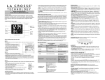
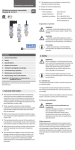
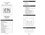
Operating instructions
Betriebsanleitung
Precision pressure transmitter models P-30, P-31
Präzisions-Druckmessumformer Typen P-30, P-31
Precision pressure transmitter model P-30
GB
D
GB Operating instructions models P30, P-31
D Betriebsanleitung Typen P30, P-31
Page
3 - 24
Seite
25 - 46
Prior to starting any work, read the operating instructions!
Keep for later use!
Vor Beginn aller Arbeiten Betriebsanleitung lesen!
Zum späteren Gebrauch aufbewahren!
2
WIKA operating instructions precision pressure transmitter model P-30, P-31
11473500.03 08/2011 GB/D
© 2011 WIKA Alexander Wiegand SE & Co. KG
All rights reserved. / Alle Rechte vorbehalten.
WIKA® is a registered trademark in various countries.
WIKA® ist eine geschützte Marke in verschiedenen Ländern.
Contents
Contents
GB
1.
General information
4
2.
Safety
6
3.
Specifications
9
4.
Design and function
13
5.
Transport, packaging and storage
14
6.
Commissioning, operation
14
7.
Maintenance and cleaning
21
8.
Faults
21
9.
Dismounting, return and disposal
23
11473500.03 08/2011 GB/D
??
Appendix 1: EC declaration of conformity for models P-30, P-31 24
Declarations of conformity can be found online at www.wika.com.
WIKA operating instructions precision pressure transmitter models P-30, P-31
3
1. General information
1. General information
■■ The pressure transmitter described in the operating instructions has been designed and
manufactured using state-of-the-art technology. All components are subject to stringent quality and
environmental criteria during production. Our management systems are certified to ISO 9001 and
ISO 14001.
■■ These operating instructions contain important information on handling the pressure transmitter.
Working safely requires that all safety instructions and work instructions are observed.
■■ Observe the relevant local accident prevention regulations and general safety regulations for the
pressure transmitter's range of use.
■■ The operating instructions are part of the product and must be kept in the immediate vicinity of the
pressure transmitter and readily accessible to skilled personnel at any time.
■■ Skilled personnel must have carefully read and understood the operating instructions prior to
beginning any work.
■■ The manufacturer's liability is void in the case of any damage caused by using the product contrary
to its intended use, non-compliance with these operating instructions, assignment of insufficiently
qualified skilled personnel or unauthorised modifications to the pressure transmitter.
■■ The general terms and conditions, contained in the sales documentation, shall apply.
■■ Subject to technical modifications.
■■ Further information:
- Internet address:
- Relevant data sheet:
- Application consultant:
4
www.wika.de / www.wika.com
PE 81.54
Tel.:
(+49) 9372/132-8976
Fax:
(+49) 9372/132-8008976
E-Mail: [email protected]
WIKA operating instructions precision pressure transmitter models P-30, P-31
11473500.03 08/2011 GB/D
GB
1. General information
Explanation of symbols
WARNING!
... indicates a potentially dangerous situation that can result in serious injury or death, if not
avoided.
CAUTION!
... indicates a potentially dangerous situation that can result in light injuries or damage to
equipment or the environment, if not avoided.
Information
… points out useful tips, recommendations and information for efficient and trouble-free
operation.
CAUTION!
... indicates a potentially dangerous situation that can result in burns, caused by hot
surfaces or liquids, if not avoided.
Abbreviations
2-wire
11473500.03 08/2011 GB/D
3-wire
U+
US+
Two of the connection lines are used for the voltage supply.
The measurement signal also provides the supply current.
Two of the connection lines are used for the voltage supply.
One connection line is used for the measurement signal.
Positive power terminal
Negative power terminal
Positive measurement terminal
WIKA operating instructions precision pressure transmitter models P-30, P-31
5
GB
2. Safety
2. Safety
WARNING!
Before installation, commissioning and operation, ensure that the appropriate pressure
transmitter has been selected in terms of measuring range, design and specific measuring
conditions.
Non-observance can result in serious injury and/or damage to the equipment.
GB
WARNING!
Open the connections only after the system has been depressurised.
Prior to opening the instrument, disconnect it from the mains.
Always operate the pressure transmitter within the overpressure limit.
Observe the working conditions in accordance with chapter 3 "Specifications".
For the application of the pressure transmitter in connection with aggressive / corrosive
media and for avoiding mechanical damages, see chapter 3 „Specifications“.
■■
■■
■■
■■
■■
Further important safety instructions can be found in the individual chapters of these
operating instructions.
2.1 Intended use
The pressure transmitter is used to convert pressure into an electrical signal.
The technical specifications contained in these operating instructions must be observed. Improper
handling or operation of the pressure transmitter outside of its technical specifications requires the
instrument to be taken out of service immediately and inspected by an authorised WIKA service
engineer.
The manufacturer shall not be liable for claims of any type based on operation contrary to the intended
use.
6
WIKA operating instructions precision pressure transmitter models P-30, P-31
11473500.03 08/2011 GB/D
The pressure transmitter has been designed and built solely for the intended use described here and
may only be used accordingly.
2. Safety
2.2 Personnel qualification
WARNING!
Risk of injury should qualification be insufficient!
Improper handling can result in considerable injury and damage to equipment.
The activities described in these operating instructions may only be carried out by skilled
personnel who have the qualifications described below.
Skilled personnel
Skilled personnel are understood to be personnel who, based on their technical training, knowledge
of measurement and control technology and on their experience and knowledge of country-specific
regulations, current standards and directives, are capable of carrying out the work described and
independently recognising potential hazards.
Special operating conditions require further appropriate knowledge, e.g. of aggressive media.
2.3 Special hazards
11473500.03 08/2011 GB/D
WARNING!
For hazardous media such as oxygen, acetylene, flammable or toxic gases or liquids,
and refrigeration plants, compressors, etc., in addition to all standard regulations, the
appropriate existing codes or regulations must also be followed.
WARNING!
Residual media in dismounted pressure transmitters can result in a risk to persons, the
environment and equipment.
Take sufficient precautionary measures.
WARNING!
When touching the pressure transmitter, please note that the surfaces of the instrument
components can become hot during operation.
WIKA operating instructions precision pressure transmitter models P-30, P-31
7
GB
2. Safety
2.4 Labelling / Safety marks
Pin assignment
Model
Measuring range
P# Product No.
S# Serial No.
Output signal
Power supply
Accuracy
If the serial number becomes illegible (e.g. due to mechanical damage or overpainting), traceability will
no longer be possible.
Explanation of symbols
General danger symbol
CE, Communauté Européenne
Instruments bearing this mark comply with the relevant European directives.
Voltage DC
8
WIKA operating instructions precision pressure transmitter models P-30, P-31
11473500.03 08/2011 GB/D
GB
Product label
3. Specifications
3. Specifications
3.1 Measuring ranges
Relative pressure
bar
psi
0 ... 0.25
0 ... 0.4
0 ... 0.6
0 ... 400
0 ... 600
0 ... 1000
0 ... 10
0 ... 5
0 ... 160
0 ... 800
0 ... 1
0 ... 1.6
0 ... 2.5
0 ... 4
0 ... 6
0 ... 15
0 ... 25
0 ... 30
0 ... 50
0 ... 60
0 ... 100
0 ... 1500
0 ... 2000
0 ... 3000
0 ... 5000
0 ... 10000
0 ... 0.4
0 ... 0.6
0 ... 1
0 ... 1.6
0 ... 2.5
0 ... 4
0 ... 6
0 ... 10
0 ... 15
0 ... 25
0 ... 30
0 ... 50
0 ... 60
0 ... 100
0 ... 16
psi
0 ... 0.25
0 ... 200
0 ... 1000 1)
0 ... 160
0 ... 200
0 ... 160
0 ... 200
0 ... 5
0 ... 25
0 ... 10
Absolute pressure
bar
GB
0 ... 250
0 ... 40
0 ... 300
Vacuum and +/- measuring range
bar
psi
-1 ... 0
-30 inHG ... 0
-1 ... 0.6
-30 inHG ... 15
-1 ... 1.5
-30 inHG ... 30
0 ... 60
0 ... 400
-1 ... 3
-30 inHG ... 60
-1 ... 5
0 ... 100
0 ... 160
0 ... 500
0 ... 600
-1 ... 9
0 ... 250
0 ... 750
-1 ... 15
-30 inHG ... 100 -30 inHG ... 160 -30 inHG ... 200
11473500.03 08/2011 GB/D
1) Applies only to P-30
Overpressure limit
■■ 3 times:
up to 16 bar
■■ 2 times:
from 16 bar
■■ 1.5 times: 0 ... 1000 psi, 0 ... 1500 psi, 0 ... 10000 psi
Vacuum resistance:
yes
WIKA operating instructions precision pressure transmitter models P-30, P-31
9
3. Specifications
3.2 Output signal
Value
4 ... 20 mA
Voltage (3-wire)
DC 0 ... 10 V
4 ... 20 mA
Current (3-wire)
-
USB
Current (2-wire, 3-wire):
Voltage (3-wire):
DC 0 ... 5 V
DC 1 ... 5 V
DC 0.5 ... 4.5 V
-
CANopen
Load in Ω
0 ... 20 mA
≤ (power supply - 9 V) / 0.02 A
> Umax / 1 mA
3.3 Voltage supply
Power supply
DC 9 ...30 V, DC 14 ... 30 V (for voltage output DC 0 ... 10 V)
Measuring rate
3-wire and CANopen: 1 ms
2-wire
2 ms
USB:
3 ms
Warm-up time
< 10 min
Total current consumption
Current output (2-wire):
Current output (3-wire):
Voltage output (3-wire):
USB:
CANopen:
10
max. 25 mA
max. 45 mA
max. 10 mA
40 mA
60 mA
WIKA operating instructions precision pressure transmitter models P-30, P-31
11473500.03 08/2011 GB/D
GB
Signal type
Current (2-wire)
3. Specifications
3.4 Accuracy
Non-linearity (IEC 61298-2)
≤ ± 0.04 % of span BFSL
GB
Accuracy at room temperature
Standard
Option
Accuracy class
≤ ± 0.1 % of span 1)
≤ ± 0.05 % of span 1) 2)
1) Including non-linearity, hysteresis, zero-point and full scale deviations (corresponds to measured error per IEC 61298-2). Calibrated in
vertical mounting position with process connection facing downwards.
2) Not possible with vacuum and +/- measuring ranges, as well as measuring ranges ≤ 0.4 bar.
Temperature error
-20 ... +10 °C: ≤ ± 0.2 % / 10 K
10 ... 60 °C:
no additional error (actively compensated)
60 ... 80 °C:
≤ ± 0.2 % / 10 K
Long-term drift per year
≤ ± 0.1 % of span
11473500.03 08/2011 GB/D
Total error band (10 ... 60 °C)
≤ ± 0.1 % of span
Adjustment and recalibration
Calibration via software "EasyCom 2011"
Zero point: -5 ... +20 % of span
Span:
-5 ... +20 % of span
WIKA operating instructions precision pressure transmitter models P-30, P-31
11
3. Specifications
3.5 Reference conditions (IEC 61298-1)
15 ... 25 °C
950 ... 1050 mbar
45 ... 75 % relative
Process connection lower mount (LM)
DC 24 V
see output signals
as required
3.6 Operating conditions
Mechanics
Vibration resistance:
Shock resistance:
Service life:
Free fall:
10 g (IEC 60068-2-6, under resonance)
200 g (IEC 60068-2-27, mechanical)
10 million load cycles
1m
Temperatures
Compensated temperature range:
Medium:
Ambient:
Storage:
-20 ... +80 °C
-20 ... +105 °C
-20 ... +80 °C
-40 ... +85 °C
3.7 Electrical safety
Short-circuit resistance:
S+ vs. 0V
CAN-High / CAN-Low vs. U+ / 0V
Reverse polarity protection: U+ vs. 0V
Overvoltage protection:
DC 36 V
Insulation voltage:
DC 500 V
12
WIKA operating instructions precision pressure transmitter models P-30, P-31
11473500.03 08/2011 GB/D
GB
Temperature:
Atmospheric pressure:
Humidity:
Nominal position:
Power supply:
Load:
Mounting position:
3. Specifications / 4. Design and function
3.8 Materials
Wetted parts
Stainless steel
Sealing material used
GB
Non-wetted parts
Stainless steel (additionally Elgiloy® for measuring ranges > 25 bar)
3.9 Approvals, directives and certificates
CE conformity
EMC directive:
Pressure equipment directive:
ROHS conformity:
1) Not with bayonet connector
2004/108/EC
EN 61326 emission (group 1, class B) and interference immunity (industrial
application)
97/23/EC
Yes 1)
11473500.03 08/2011 GB/D
4. Design and function
4.1 Description
By means of a sensor element and by applying power, the prevailing pressure is converted into an
amplified standardised electrical signal via the deformation of a diaphragm. This electrical signal varies
in proportion to the pressure and can be evaluated accordingly.
4.2 Scope of delivery
Cross-check scope of delivery with the delivery note.
Flush design (P-31) with pre-mounted sealings and protection cap.
For model P-31, the sealing ring is included in the delivery.
WIKA operating instructions precision pressure transmitter models P-30, P-31
13
5. Transport, packaging and storage / 6. Commissioning, ...
5. Transport, packaging and storage
5.1 Transport
Check the instrument for any damage that may have been caused during transportation.
Obvious damage must be reported immediately.
5.2 Packaging
Do not remove packaging until just before mounting.
Keep the packaging as it will provide optimum protection during transport (e.g. change in installation
site, sending for repair).
Keep the protection cap of the process connection for later transport or storage.
5.3 Storage
Permissible conditions at the place of storage:
■■ Storage temperature: -20 ... +80 °C
■■ Humidity: 45 ... 75 % relative humidity (no condensation)
WARNING!
Before storing the pressure transmitter (following operation), remove any residual media.
This is of particular importance if the medium is hazardous to health, e.g. caustic, toxic,
carcinogenic, radioactive, etc.
6. Commissioning, operation
CAUTION!
Prior to commissioning, the pressure transmitter must be subjected to a visual inspection.
■■ Check the diaphragm for any visible damage, since this is a safety-relevant component.
■■ Leaking fluid is indicative of damage.
■■ Only use the pressure transmitter if it is in perfect condition with respect to safety.
14
WIKA operating instructions precision pressure transmitter models P-30, P-31
11473500.03 08/2011 GB/D
GB
6. Commissioning, operation
6.1 Making the mechanical connection
Required tool: Open-ended spanner (spanner width 27 or 41)
GB
■■ With flush process connections, remove the protection cap not until shortly
before mounting. During installation, ensure that the diaphragm is not
damaged.
■■ During mounting, make sure that the sealing faces at the pressure
transmitter and the measuring point are clean and undamaged.
■■ Only ever screw in, or unscrew, the instrument via the spanner flats. Never
max. 10 Nm
use the case as a working surface.
■■ The correct torque depends on the dimensions of the process connection
and the sealing used (form/material).
■■ When screwing in, avoid any jamming of the threads.
■■ For information on tapped holes and welding sockets, see Technical Information IN 00.14 at
www.wika.com.
11473500.03 08/2011 GB/D
Types of sealing
Parallel threads
per EN 837
Tapered threads
NPT, R and PT
per DIN 3852-E
1
1
WIKA operating instructions precision pressure transmitter models P-30, P-31
15
6. Commissioning, operation
For further information on sealings see WIKA data sheet AC 09.08 or under www.wika.com.
Models P-30 and P-31 are high-quality precision measuring instruments. Installationrelated influences (e.g. position dependence, tightening torque) must be eliminated
by correcting the zero point in the application or via the software "EasyCom". Thus an
optimum measuring accuracy of the overall system is ensured.
Fitting a DIN 175301-803 angular connector
(D) Mounting hole
(2)
(1)
(3)
(4)
(5)
Line connector
(female)
1. Loosen the screw (1).
2. Loosen the cable gland (2).
3. Pull the angle housing (5), with the terminal block (6)
inside, away from the instrument.
4. Via the mounting hole (D), lever the terminal block (6) out
of the angle housing (5). Do not try to push the terminal
block (6) out using the screw hole (1) or the cable gland
(2), otherwise the sealing of the angle housing could be
damaged.
16
(6)
Sealing
Instrument
connector (male),
case with process
connection
WIKA operating instructions precision pressure transmitter models P-30, P-31
11473500.03 08/2011 GB/D
GB
Correct sealing of the process connections with parallel threads 1 must be made using suitable flat
gaskets, sealing rings or WIKA profile sealings.
The sealing of tapered threads (e.g. NPT threads) is made by providing the thread with additional
sealing material such as, for example, PTFE tape (EN 837-2).
6. Commissioning, operation
5. Select a conductor with an outer diameter matched to the angle housing's cable gland. Slide the
cable through the cable gland (2), ring (3), sealing (4) and angle housing (5).
6. Connect the cable ends to the appropriate connection terminals on the terminal block (6) (see table
"Connection diagrams").
7. Press the angle housing (5) onto the terminal block (6).
8. Tighten the cable gland (2) around the cable. Make sure that the sealings are not damaged and that
the cable gland and sealings are assembled correctly in order to ensure ingress protection.
9. Place the flat, square gasket over the pressure transmitter's connection pins.
10. Slide the terminal block (6) onto the pressure transmitter's connection pins.
11. Secure the angle housing (5) and terminal block (6) to the pressure transmitter with the screw (1).
6.2 Making the electrical connection
■■ The instrument must be earthed via the process connection.
■■ Select a cable diameter that matches the cable gland of the connector. Make sure that the cable
gland of the mounted connector has a tight fit and that the sealings are present and undamaged.
Tighten the threaded connection and check that the seal is correctly seated, in order to ensure a
tight seal.
11473500.03 08/2011 GB/D
■■ For cable outlets, make sure that no moisture enters at the cable end.
WIKA operating instructions precision pressure transmitter models P-30, P-31
17
GB
6. Commissioning, operation
Connection diagrams
Assignment
2-wire
3-wire
U+
0V
1
1
S+
2
2
3
Bayonet connector
Assignment
2-wire
3-wire
U+
S+
B
B
C
CANopen M12 x 1 (5-pin)
Assignment
U+
1
1
0V
3
3
S+
4
Assignment
2-wire
3-wire
U+
3
3
0V
1
4
S+
1
Cable outlet unshielded
UB+
UB-
Shield
CANHigh
2
3
1
4
18
2-wire
3-wire
Circular connector M16 x 0.75 (5-pin)
0V
A
A
Assignment
CANLow
5
Assignment
2-wire
3-wire
U+
brown
brown
0V
blue
blue
S+
black
WIKA operating instructions precision pressure transmitter models P-30, P-31
11473500.03 08/2011 GB/D
GB
Circular connector M12 x 1 (4-pin)
Angular connector DIN 175301-803 A
6. Commissioning, operation
Specifications
Description
Ingress protection
Angular connector DIN 175301-803 A
IP 65
Circular connector M16 x 0.75 (5-pin)
IP 67
Circular connector M12 x 1 (4-pin)
Bayonet connector
CANopen M12 x 1 (5-pin)
USB
GB
IP 67
IP 67
IP 67
IP 67
IP 67
Cable outlet
The stated ingress protection (per IEC 60529) only applies when plugged in using
mating connectors that have the appropriate ingress protection.
6.3 Functional check
The output signal must be proportional to the prevailing pressure. If this is not the case, this may indicate
a damaged diaphragm. In this case, see chapter 8 "Faults".
6.4 Installation of the service interface
Only required for analogue instruments
11473500.03 08/2011 GB/D
Hardware requirement:
■■ Spare USB port
■■ USB adapter cable (order No.: 13193075 incl. software CD)
■■ Suitable voltage supply for the pressure transmitter
System requirement:
■■ 32-bit operating system Microsoft® Windows® 2000, XP, Vista or Windows® 7
■■ WIKA software EasyCom 2011 (CD containing software included with order No.: 13193075 or is
available for download at www.wika.com)
WIKA operating instructions precision pressure transmitter models P-30, P-31
19
6. Commissioning, operation
Fitting of USB adapter cable
1. Switch the pressure transmitter to a depressurised state.
3. Connect the spade plug of the USB adapter cable to the
instrument‘s USB connection 1 .
4. Connect the USB connector of the adapter cable to the free
USB port of the computer.
Sealing
Clamping nut
Instrument connector
Sealing
1
Case with process
connection
5. Connect pressure transmitter to power supply.
6.5 Commissioning of USB instruments
For installing the driver, administrator rights are required.
Connect the USB connector with a USB 2.0 port to the computer.
Install the driver via the InstallWizard of the product software.
For further operation the P-3x data logger software is available (for details see instruction manual
P-3x data logger)
■■ Details on the interface protocol or the DLL (Dynamic Link Library) are available on the software CD
and in the download section at www.wika.com.
■■
■■
■■
■■
All files and documents are available for download at www.wika.com.
6.6 Commissioning of CANopen instruments
■■ Connect the CAN interface (e.g. PEAK PCAN-USB) to the PC and the pressure transmitter.
■■ Start the CAN software (e.g. PEAK PCAN-View).
■■ Make sure that the correct bit rate and node ID of the pressure transmitter is used.
For further information see "Quick Start Guide" under "Additional Instructions".
20
WIKA operating instructions precision pressure transmitter models P-30, P-31
11473500.03 08/2011 GB/D
GB
2. Remove the clamping nut and carefully pull out the instrument
connector.
Mating connector
7. Maintenance and cleaning / 8. Faults
7. Maintenance and cleaning
7.1 Maintenance
This instrument is maintenance-free.
Repairs must only be carried out by the manufacturer.
GB
7.2 Cleaning
CAUTION!
■■ Before cleaning, correctly disconnect the instrument from the pressure supply, switch it
off and disconnect it from the mains.
■■ Clean the instrument with a moist cloth.
■■ Residual media in dismounted instruments can result in a risk to persons, the
environment and equipment. Take sufficient precautionary measures.
■■ Do not use any pointed or hard objects for cleaning, since the diaphragm of the process
connection must not be damaged.
For information on returning the instrument see chapter 9.2 "Return".
8. Faults
11473500.03 08/2011 GB/D
In the event of any faults, first check whether the pressure transmitter is mounted correctly,
mechanically and electrically.
Faults
No output signal
Causes
Measures
Cable break
Check the through drilling
No / wrong power supply or current
pulse
Correct the power supply
WIKA operating instructions precision pressure transmitter models P-30, P-31
21
8. Faults
Faults
Constant output signal upon
change in pressure
No communication
No cyclic transmission
Signal span too small / drops
Signal span varies / inaccurate
Deviating zero point signal
Wiring error
Mechanical overload caused by
overpressure
Adjustment of node ID
Transmission rate incorrect
PDO mapping
Transmission type incorrect
Mechanical overload caused by overpressure
Measures
Observe the pin assignment
Replace instrument; if it fails repeatedly,
contact the manufacturer
Check the configuration parameters
Check the configuration parameters
Replace instrument; if it fails repeatedly,
contact the manufacturer
Diaphragm damaged, e.g. due to
Contact manufacturer and replace
impacts, abrasive / aggressive medium; instrument
corrosion at diaphragm / process
connection; transmission medium
missing
Clean the sealing/sealing face, replace
Sealing / sealing face damaged / soiled, sealing if applicable
sealing does not have a tight fit, threads
jammed
EMC interference sources in the environ- Shield instrument; cable shield; remove
ment; e.g. frequency converter
source of interference
Operating temperatures too high/low
Observe the permissible temperatures
Instrument not earthed
Earth the instrument
Strongly varying pressure of the process Damping; consulting by the manufacturer
medium
Operating temperature too high/low
Permissible temperatures
Other mounting position
Correct the zero point via potentiometer or
key pad or software
Overpressure limit exceeded
Observe the permissible overpressure limit
If complaint is unjustified, we will charge you the complaint processing fees.
22
WIKA operating instructions precision pressure transmitter models P-30, P-31
11473500.03 08/2011 GB/D
GB
Causes
No / wrong output signal
9. Dismounting, return and disposal
CAUTION!
If faults cannot be eliminated by means of the measures listed above, the instrument must
be shut down immediately, and it must be ensured that pressure and/or signal are no
longer present, and it must be prevented from being inadvertently put back into service. In
this case, contact the manufacturer. If a return is needed, follow the instructions given in
chapter 9.2 "Return".
9. Dismounting, return and disposal
WARNING!
Residual media in dismounted pressure transmitters can result in a risk to persons, the
environment and equipment.
Take sufficient precautionary measures.
9.1 Dismounting
Only disconnect the pressure transmitter once the system has been depressurised!
In order to protect the diaphragm of flush instruments, it is provided with a protection cap.
9.2 Return
WARNING!
Absolutely observe when shipping the pressure transmitter:
All pressure transmitters delivered to WIKA must be free from any kind of hazardous
substances (acids, leachate, solutions, etc.).
11473500.03 08/2011 GB/D
When returning the pressure transmitter, use the original packaging or a suitable transport package.
Enclose the completed returns form with the pressure transmitter.
The returns form is available on the internet:
www.wika.com / Service / Return
9.3 Disposal
Incorrect disposal can put the environment at risk.
Dispose of instrument components and packaging materials in an environmentally compatible way and
in accordance with the country-specific waste disposal regulations.
WIKA operating instructions precision pressure transmitter models P-30, P-31
23
GB
Appendix 1: EC declaration of conformity for models P-30, P-31
24
WIKA operating instructions precision pressure transmitter models P-30, P-31
11473500.03 08/2011 GB/D
GB
Inhalt
11473500.03 08/2011 GB/D
Inhalt
1.
Allgemeines
26
2.
Sicherheit
28
3.
Technische Daten
31
4.
Aufbau und Funktion
35
5.
Transport, Verpackung und Lagerung
36
6.
Inbetriebnahme, Betrieb
36
7.
Wartung und Reinigung
43
8.
Störungen
43
9.
Demontage, Rücksendung und Entsorgung
45
Anlage 1: EG-Konformitätserklärung Typen P-30, P-31
46
Konformitätserklärungen finden Sie online unter www.wika.de.
WIKA Betriebsanleitung Präzisions-Druckmessumformer Typen P-30, P-31
25
D
1. Allgemeines
1. Allgemeines
■■ Der in der Betriebsanleitung beschriebene Druckmessumformer wird nach den neuesten
■■ Diese Betriebsanleitung gibt wichtige Hinweise zum Umgang mit dem Druckmessumformer.
Voraussetzung für sicheres Arbeiten ist die Einhaltung aller angegebenen Sicherheitshinweise und
Handlungsanweisungen.
■■ Die für den Einsatzbereich des Druckmessumformers geltenden örtlichen Unfallverhütungsvorschriften
und allgemeinen Sicherheitsbestimmungen einhalten.
■■ Die Betriebsanleitung ist Produktbestandteil und muss in unmittelbarer Nähe des Druckmessumformers
für das Fachpersonal jederzeit zugänglich aufbewahrt werden.
■■ Das Fachpersonal muss die Betriebsanleitung vor Beginn aller Arbeiten sorgfältig durchgelesen und
verstanden haben.
■■ Die Haftung des Herstellers erlischt bei Schäden durch bestimmungswidrige Verwendung,
Nichtbeachten dieser Betriebsanleitung, Einsatz ungenügend qualifizierten Fachpersonals sowie
eigenmächtiger Veränderung am Druckmessumformer.
■■ Es gelten die allgemeinen Geschäftsbedingungen in den Verkaufsunterlagen.
■■ Technische Änderungen vorbehalten.
■■ Weitere Informationen:
- Internet-Adresse:
- zugehöriges Datenblatt:
- Anwendungsberater:
26
www.wika.de / www.wika.com
PE 81.54
Tel.:
(+49) 9372/132-8976
Fax:
(+49) 9372/132-8008976
E-Mail: [email protected]
WIKA Betriebsanleitung Präzisions-Druckmessumformer Typen P-30, P-31
11473500.03 08/2011 GB/D
D
Erkenntnissen konstruiert und gefertigt.
Alle Komponenten unterliegen während der Fertigung strengen Qualitäts- und Umweltkriterien.
Unsere Managementsysteme sind nach ISO 9001 und ISO 14001 zertifiziert.
1. Allgemeines
Symbolerklärung
WARNUNG!
… weist auf eine möglicherweise gefährliche Situation hin, die zum Tod oder zu schweren
Verletzungen führen kann, wenn sie nicht gemieden wird.
VORSICHT!
… weist auf eine möglicherweise gefährliche Situation hin, die zu geringfügigen oder
leichten Verletzungen bzw. Sach- und Umweltschäden führen kann, wenn sie nicht
gemieden wird.
Information
… hebt nützliche Tipps und Empfehlungen sowie Informationen für einen effizienten und
störungsfreien Betrieb hervor.
VORSICHT!
… weist auf eine möglicherweise gefährliche Situation hin, die durch heiße Oberflächen
oder Flüssigkeiten zu Verbrennungen führen kann, wenn sie nicht gemieden wird.
Abkürzungen
2-Leiter
11473500.03 08/2011 GB/D
3-Leiter
U+
US+
Zwei Anschlussleitungen dienen zur Spannungsversorgung.
Der Speisestrom ist das Messsignal.
Zwei Anschlussleitungen dienen zur Spannungsversorgung.
Eine Anschlussleitung dient für das Messsignal.
Positiver Versorgungsanschluss
Negativer Versorgungsanschluss
Positiver Messanschluss
WIKA Betriebsanleitung Präzisions-Druckmessumformer Typen P-30, P-31
27
D
2. Sicherheit
2. Sicherheit
WARNUNG!
Vor Montage, Inbetriebnahme und Betrieb sicherstellen, dass der richtige
Druckmessumformer hinsichtlich Messbereich, Ausführung und spezifischen
Messbedingungen ausgewählt wurde.
Bei Nichtbeachten können schwere Körperverletzungen und/oder Sachschäden auftreten.
D
WARNUNG!
Anschlüsse nur im drucklosen Zustand öffnen.
Vor dem Öffnen das Gerät ordnungsgemäß vom Netz trennen.
Druckmessumformer nur innerhalb der Überlast-Druckgrenze betreiben.
Betriebsparameter gemäß Kapitel 3 „Technische Daten“ beachten.
Zur Verwendung des Druckmessumformers in Verbindung mit aggressiven / korrosiven
Medien und zur Vermeidung von mechanischen Gefährdungen ist Kapitel 3 „Technische
Daten“ zu beachten
■■
■■
■■
■■
■■
Weitere wichtige Sicherheitshinweise befinden sich in den einzelnen Kapiteln dieser
Betriebsanleitung.
Der Druckmessumformer ist ausschließlich für den hier beschriebenen bestimmungsgemäßen
Verwendungszweck konzipiert und konstruiert und darf nur dementsprechend verwendet werden.
Die technischen Spezifikationen in dieser Betriebsanleitung sind einzuhalten. Eine unsachgemäße
Handhabung oder ein Betreiben des Druckmessumformers außerhalb der technischen Spezifikationen
macht die sofortige Stilllegung und Überprüfung durch einen autorisierten WIKA-Servicemitarbeiter
erforderlich.
Ansprüche jeglicher Art aufgrund von nicht bestimmungsgemäßer Verwendung sind ausgeschlossen.
28
WIKA Betriebsanleitung Präzisions-Druckmessumformer Typen P-30, P-31
11473500.03 08/2011 GB/D
2.1 Bestimmungsgemäße Verwendung
Der Druckmessumformer dient zum Umwandeln von Druck in ein elektrisches Signal.
2. Sicherheit
2.2 Personalqualifikation
WARNUNG!
Verletzungsgefahr bei unzureichender Qualifikation!
Unsachgemäßer Umgang kann zu erheblichen Personen- und Sachschäden führen.
Die in dieser Betriebsanleitung beschriebenen Tätigkeiten nur durch Fachpersonal nachfolgend beschriebener Qualifikation durchführen lassen.
Fachpersonal
Das Fachpersonal ist aufgrund seiner fachlichen Ausbildung, seiner Kenntnisse der Mess- und
Regelungstechnik und seiner Erfahrungen sowie Kenntnis der landesspezifischen Vorschriften,
geltenden Normen und Richtlinien in der Lage, die beschriebenen Arbeiten auszuführen und mögliche
Gefahren selbstständig zu erkennen.
Spezielle Einsatzbedingungen verlangen weiteres entsprechendes Wissen, z. B. über aggressive
Medien.
2.3 Besondere Gefahren
11473500.03 08/2011 GB/D
WARNUNG!
Bei gefährlichen Messstoffen wie z. B. Sauerstoff, Acetylen, brennbaren oder giftigen
Stoffen, sowie bei Kälteanlagen, Kompressoren etc. müssen über die gesamten
allgemeinen Regeln hinaus die einschlägigen Vorschriften beachtet werden.
WARNUNG!
Messstoffreste in ausgebauten Druckmessumformern können zur Gefährdung von
Personen, Umwelt und Einrichtung führen.
Ausreichende Vorsichtsmaßnahmen ergreifen.
WARNUNG!
Beim Berühren des Druckmessumformer beachten, dass die Oberflächen der Gerätekomponenten während des Betriebes heiß werden können.
WIKA Betriebsanleitung Präzisions-Druckmessumformer Typen P-30, P-31
29
D
2. Sicherheit
2.4 Beschilderung / Sicherheitskennzeichnungen
Typenschild
Anschlussbelegung
D
Typ
Messbereich
P# Erzeugnis-Nr.
S# Serien-Nr.
Ausgangssignal
Hilfsenergie
Genauigkeit
Wird die Seriennummer unleserlich (z. B. durch mechanische Beschädigung oder Übermalen), ist eine
Rückverfolgbarkeit nicht mehr möglich.
Symbolerklärung
CE, Communauté Européenne
Geräte mit dieser Kennzeichnung stimmen überein mit den zutreffenden europäischen
Richtlinien.
Gleichspannung
30
WIKA Betriebsanleitung Präzisions-Druckmessumformer Typen P-30, P-31
11473500.03 08/2011 GB/D
Allgemeines Gefahrensymbol
3. Technische Daten
3. Technische Daten
3.1 Messbereiche
Relativdruck
bar
psi
0 ... 0,25
0 ... 0,4
0 ... 0,6
0 ... 400
0 ... 600
0 ... 1000
0 ... 10
0 ... 5
0 ... 160
0 ... 800
Absolutdruck
bar
psi
0 ... 0,25
0 ... 1
0 ... 1,6
0 ... 2,5
0 ... 4
0 ... 6
0 ... 15
0 ... 25
0 ... 30
0 ... 50
0 ... 60
0 ... 100
0 ... 1000 1)
0 ... 1500
0 ... 2000
0 ... 3000
0 ... 5000
0 ... 10000
0 ... 0,4
0 ... 0,6
0 ... 1
0 ... 1,6
0 ... 2,5
0 ... 4
0 ... 6
0 ... 10
0 ... 15
0 ... 25
0 ... 30
0 ... 50
0 ... 60
0 ... 100
0 ... 16
0 ... 10
0 ... 200
0 ... 160
0 ... 200
0 ... 160
0 ... 200
0 ... 5
0 ... 25
0 ... 250
0 ... 40
0 ... 300
Vakuum- und +/- Messbereich
bar
psi
-1 ... 0
-30 inHG ... 0
-1 ... 0,6
-30 inHG ... 15
-1 ... 1,5
-30 inHG ... 30
0 ... 60
0 ... 400
-1 ... 3
-30 inHG ... 60
-1 ... 5
0 ... 100
0 ... 160
0 ... 500
0 ... 600
-1 ... 9
D
0 ... 250
0 ... 750
-1 ... 15
-30 inHG ... 100 -30 inHG ... 160 -30 inHG ... 200
11473500.03 08/2011 GB/D
1) nur für P-30 gültig
Überlast-Druckgrenze
■■ 3-fach:
bis 16 bar
■■ 2-fach:
ab 16 bar
■■ 1,5-fach: 0 ... 1000 psi, 0 ... 1500 psi, 0 ... 10000 psi
Vakuumfestigkeit: ja
WIKA Betriebsanleitung Präzisions-Druckmessumformer Typen P-30, P-31
31
3. Technische Daten
3.2 Ausgangssignal
Signalart
4 ... 20 mA
Spannung (3-Leiter)
DC 0 ... 10 V
4 ... 20 mA
Strom (3-Leiter)
-
USB
0 ... 20 mA
DC 0 ... 5 V
DC 1 ... 5 V
DC 0,5 ... 4,5 V
-
CANopen
Bürde in Ω
Strom (2-Leiter, 3-Leiter): ≤ (Hilfsenergie - 9 V) / 0,02 A
Spannung (3-Leiter):
> Umax / 1 mA
3.3 Spannungsversorgung
Hilfsenergie
DC 9 ...30 V, DC 14 ... 30 V (für Spannungsausgang DC 0 ... 10 V)
Messrate
3-Leiter und CANopen: 1 ms
2-Leiter
2 ms
USB:
3 ms
Aufwärmzeit
< 10 min
Gesamtstromaufnahme
Stromausgang (2-Leiter):
Stromausgang (3-Leiter):
Spannungausgang (3-Leiter):
USB:
CANopen:
32
max. 25 mA
max. 45 mA
max. 10 mA
40 mA
60 mA
WIKA Betriebsanleitung Präzisions-Druckmessumformer Typen P-30, P-31
11473500.03 08/2011 GB/D
D
Wert
Strom (2-Leiter)
3. Technische Daten
3.4 Genauigkeit
Nichtlinearität (IEC 61298-2)
≤ ± 0,04 % der Spanne BFSL
Genauigkeit bei Raumtemperatur
Standard
Option
D
Genauigkeitsklasse
≤ ± 0,1 % der Spanne 1)
≤ ± 0,05 % der Spanne 1) 2)
1) Einschließlich Nichtlinearität, Hysterese, Nullpunkt- und Endwertabweichung (entspricht Messabweichung nach IEC 61298-2). Kalibriert
bei senkrechter Einbaulage mit Prozessanschluss nach unten.
2) Nicht möglich bei Vakuum- und +/- Messbereichen, sowie bei Messbereichen ≤ 0,4 bar.
Temperaturfehler
-20 ... +10 °C: ≤ ± 0,2 % / 10 K
10 ... 60 °C:
kein zusätzlicher Fehler (aktiv kompensiert)
60 ... 80 °C:
≤ ± 0,2 % / 10 K
Langzeitdrift pro Jahr
≤ ± 0,1 % der Spanne
11473500.03 08/2011 GB/D
Gesamtfehlerband (10 ... 60 °C)
≤ ± 0,1 % der Spanne
Einstellbarkeit und Nachkalibrierung
Kalibrierung über Software „EasyCom 2011“
Nullpunkt: -5 ... +20 % der Spanne
Spanne:
-5 ... +20 % der Spanne
WIKA Betriebsanleitung Präzisions-Druckmessumformer Typen P-30, P-31
33
3. Technische Daten
3.5 Referenzbedingungen (IEC 61298-1)
15 ... 25 °C
950 ... 1050 mbar
45 ... 75 % relativ
Prozessanschluss unten
DC 24 V
siehe Ausgangssignale
beliebig
3.6 Einsatzbedingungen
Mechanik
Vibrationsfestigkeit:
Schockfestigkeit:
Lebensdauer:
Freier Fall:
10 g (IEC 60068-2-6, bei Resonanz)
200 g (IEC 60068-2-27, mechanisch)
10 Millionen Lastwechsel
1m
Temperaturen
Kompensierter Temperaturbereich: -20 ... +80 °C
Medium:
-20 ... +105 °C
Umgebung: -20 ... +80 °C
Lager:
-40 ... +85 °C
3.7 Elektrische Sicherheit
Kurzschlussfestigkeit:
Verpolschutz:
Überspannungsschutz:
Isolationsspannung:
34
S+ gegen 0V
CAN-High / CAN-Low gegen U+ / 0V
U+ gegen 0V
DC 36 V
DC 500 V
WIKA Betriebsanleitung Präzisions-Druckmessumformer Typen P-30, P-31
11473500.03 08/2011 GB/D
D
Temperatur:
Luftdruck:
Luftfeuchte:
Nennlage:
Hilfsenergie:
Bürde:
Einbaulage:
3. Technische Daten / 4. Aufbau und Funktion
3.8 Werkstoffe
Messstoffberührte Teile
CrNi-Stahl
Verwendetes Dichtungsmaterial
D
Nicht messstoffberührte Teile
CrNi-Stahl (zusätzlich Elgiloy® für Messbereiche > 25 bar)
3.9 Zulassungen, Richtlinien und Zertifikate
CE-Konformität
EMV-Richtline:
Druckgeräterichtlinie:
RoHS-Konformität:
1) Nicht mit Bajonettstecker
2004/108/EG
EN 61326 Emission (Gruppe 1, Klasse B) und Störfestigkeit (industrieller Bereich)
97/23/EG
Ja 1)
11473500.03 08/2011 GB/D
4. Aufbau und Funktion
4.1 Beschreibung
Mittels Sensorelement und unter Zuführung von Hilfsenergie wird über die Verformung einer Membrane
der anstehende Druck in ein verstärktes standardisiertes elektrisches Signal umgewandelt. Dieses
elektrische Signal verändert sich proportional zum Druck und kann entsprechend ausgewertet werden.
4.2 Lieferumfang
Lieferumfang mit dem Lieferschein abgleichen.
Frontbündige Ausführung (P-31) mit vormontierten Dichtungen und Schutzkappe.
Bei Typ P-31 ist der Dichtring im Lieferumfang enthalten.
WIKA Betriebsanleitung Präzisions-Druckmessumformer Typen P-30, P-31
35
5. Transport, Verpackung und Lagerung / 6. Inbetriebnahme, ...
5. Transport, Verpackung und Lagerung
5.2 Verpackung
Verpackung erst unmittelbar vor der Montage entfernen.
Die Verpackung aufbewahren, denn diese bietet bei einem Transport einen optimalen Schutz
(z. B. wechselnder Einbauort, Reparatursendung).
Die Schutzkappe des Prozessanschlusses für den späteren Transport oder eine Lagerung aufbewahren.
5.3 Lagerung
Zulässige Bedingungen am Lagerort:
■■ Lagertemperatur: -20 ... +80 °C
■■ Feuchtigkeit: 45 ... 75 % relative Feuchte (keine Betauung)
WARNUNG!
Vor der Einlagerung des Druckmessumformers (nach Betrieb) alle anhaftenden
Messstoffreste entfernen. Dies ist besonders wichtig, wenn der Messstoff
gesundheitsgefährdend ist, wie z. B. ätzend, giftig, krebserregend, radioaktiv, usw.
6. Inbetriebnahme, Betrieb
VORSICHT!
Vor der Inbetriebnahme den Druckmessumformer optisch prüfen.
■■ Die Membrane optisch auf Beschädigung überprüfen, diese ist ein sicherheitsrelevantes
Teil.
■■ Auslaufende Flüssigkeit weist auf eine Beschädigung hin.
■■ Den Druckmessumformer nur in sicherheitstechnisch einwandfreiem Zustand einsetzen.
36
WIKA Betriebsanleitung Präzisions-Druckmessumformer Typen P-30, P-31
11473500.03 08/2011 GB/D
D
5.1 Transport
Gerät auf eventuell vorhandene Transportschäden untersuchen.
Offensichtliche Schäden unverzüglich mitteilen.
6. Inbetriebnahme, Betrieb
6.1 Montage mechanischer Anschluss
Benötigtes Werkzeug: Gabelschlüssel (Schlüsselweite 27 bzw. 41)
D
■■ Bei frontbündigen Prozessanschlüssen die Schutzkappe erst kurz vor
der Montage entfernen. Während dem Einbau sicherstellen, dass die
Membrane nicht beschädigt wird.
■■ Bei der Montage auf saubere und unbeschädigte Dichtflächen am Gerät
und an der Messstelle achten.
■■ Das Gerät nur über die Schlüsselflächen ein- bzw. ausschrauben. Niemals
max. 10 Nm
das Gehäuse als Angriffsfläche verwenden.
■■ Das richtige Drehmoment ist abhängig von der Dimension des
Prozessanschlusses sowie der verwendeten Dichtung (Form/Werkstoff).
■■ Beim Einschrauben die Gewindegänge nicht verkanten.
■■ Angaben zu Einschraublöchern und Einschweißstutzen siehe Technische Information
IN 00.14 unter www.wika.de.
Dichtungsarten
11473500.03 08/2011 GB/D
Zylindrische Gewinde
nach EN 837
Kegelige Gewinde
NPT, R und PT
nach DIN 3852-E
1
1
WIKA Betriebsanleitung Präzisions-Druckmessumformer Typen P-30, P-31
37
6. Inbetriebnahme, Betrieb
Zur Abdichtung der Prozessanschlüsse mit zylindrischem Gewinde an der Dichtfläche 1 sind Flachdichtungen, Dichtlinsen oder WIKA-Profildichtungen einzusetzen.
Bei kegeligem Gewinde (z. B. NPT-Gewinde) erfolgt die Abdichtung im Gewinde, mit zusätzlichen Dichtwerkstoffen, wie z. B. PTFE-Band (EN 837-2).
D
Hinweise zu Dichtungen siehe WIKA Datenblatt AC 09.08 oder unter www.wika.de.
Die Typen P-30 und P-31 sind hochwertige Präzisionsdruckmessgeräte. Einbaubedingte
Einflüsse (z. B. Lageabhängigkeit, Anzugsmoment) sind durch Korrektur des Nullpunktes
in der Anwendung oder über die Software „EasyCom“ zu beseitigen. Dadurch ist eine
optimale Messgenauigkeit des Gesamtsystems sichergestellt.
Montage Winkelstecker DIN 175301-803
(2)
(1)
(3)
(4)
(5)
Leitungsstecker
(Buchse)
1. Die Schraube (1) lösen.
2. Die Kabelverschraubung (2) lösen.
3. Das Winkelgehäuse (5) mit Klemmblock (6) vom Gerät
abziehen.
4. Über die Montageöffnung (D) den Klemmblock (6)
aus dem Winkelgehäuse (5) hebeln. Den Klemmblock
(6) nicht durch die Schraubenöffnung (1) bzw.
Kabelverschraubung (2) herausdrücken, sonst wird die
Dichtung des Winkelgehäuses beschädigt.
38
(6)
Dichtung
Gerätestecker
(male), Gehäuse
mit Prozessanschluss
WIKA Betriebsanleitung Präzisions-Druckmessumformer Typen P-30, P-31
11473500.03 08/2011 GB/D
(D) Montageöffnung
6. Inbetriebnahme, Betrieb
5. Den Leitungsaußendurchmesser passend zur Kabeldurchführung des Winkelgehäuses wählen.
Das Kabel durch Kabelverschraubung (2), Ring (3), Dichtung (4) und Winkelgehäuse (5) schieben.
6. Die Kabelenden entsprechend in den Anschlussklemmen des Klemmblocks (6) anschließen (siehe
Tabelle „Anschlussschemen“).
7. Das Winkelgehäuse (5) auf den Klemmblock (6) drücken.
8. Das Kabel über die Kabelverschraubung (2) verschrauben. Darauf achten, dass die Dichtungen
unbeschädigt sind und Kabelverschraubung und Dichtungen korrekt sitzen, um die Schutzart zu
gewährleisten.
9. Die quadratische Flachdichtung über die Anschlusspins des Druckmessumformers legen.
10. Den Klemmblock (6) auf die Anschlusspins des Druckmessumformers schieben.
11. Mit der Schraube (1) das Winkelgehäuse (5) mit dem Klemmblock (6) am Druckmessumformer
verschrauben.
6.2 Montage elektrischer Anschluss
■■ Das Gerät über den Prozessanschluss erden.
■■ Den Kabeldurchmesser passend zur Kabeldurchführung des Steckers wählen. Darauf achten, dass
die Kabelverschraubung des montierten Steckers korrekt sitzt und dass die Dichtungen vorhanden
und nicht beschädigt sind. Verschraubung festziehen und den korrekten Sitz der Dichtungen
überprüfen, um die Schutzart zu gewährleisten.
11473500.03 08/2011 GB/D
■■ Bei Kabelausgängen sicherstellen, dass am Ende des Kabels keine Feuchtigkeit eintritt.
WIKA Betriebsanleitung Präzisions-Druckmessumformer Typen P-30, P-31
39
D
6. Inbetriebnahme, Betrieb
Anschlussschemen
Winkelstecker DIN 175301-803 A
Belegung
2-Leiter
3-Leiter
U+
0V
1
1
S+
2
2
3
Bajonettstecker
Belegung
2-Leiter
3-Leiter
2-Leiter
3-Leiter
U+
1
1
0V
3
3
S+
4
Rundstecker M16 x 0,75 (5-polig)
U+
0V
A
A
S+
B
B
C
CANopen M12 x 1 (5-polig)
Belegung
Belegung
2-Leiter
3-Leiter
U+
3
3
0V
1
4
S+
1
Kabelausgang ungeschirmt
UB+
UB-
Schirm
CANHigh
2
3
1
4
40
Belegung
CANLow
5
Belegung
2-Leiter
3-Leiter
U+
braun
braun
0V
blau
blau
S+
schwarz
WIKA Betriebsanleitung Präzisions-Druckmessumformer Typen P-30, P-31
11473500.03 08/2011 GB/D
D
Rundstecker M12 x 1 (4-polig)
6. Inbetriebnahme, Betrieb
Spezifikationen
Bezeichnung
Schutzart
Winkelstecker DIN 175301-803 A
IP 65
Rundstecker M16 x 0,75 (5-polig)
IP 67
Rundstecker M12 x 1 (4-polig)
Bajonettstecker
CANopen M12 x 1 (5-polig)
USB
Kabelausgang
IP 67
D
IP 67
IP 67
IP 67
IP 67
Die angegebenen Schutzarten (nach IEC 60529) gelten nur im gesteckten Zustand mit
Gegensteckern entsprechender Schutzart.
6.3 Funktionsprüfung
Das Ausgangssignal muss sich dem anstehenden Druck proportional verhalten. Wenn dies nicht so ist,
kann das ein Hinweis auf eine Beschädigung der Membrane sein. In diesem Fall in Kapitel 8 „Störungen“
nachlesen.
6.4 Installation der Service Schnittstelle
Nur bei Analog-Geräten erforderlich
11473500.03 08/2011 GB/D
Hardwarevoraussetzung:
■■ Einen freien USB-Port
■■ USB-Adapterkabel (Bestellnr.: 13193075 inkl. Software-CD)
■■ Geeignete Spannungsversorgung für den Druckmessumformer
Systemvoraussetzung:
■■ 32-Bit Betriebssystem Microsoft® Windows® 2000, XP, Vista oder Windows® 7
■■ WIKA Software EasyCom 2011 (CD mit Software ist enthalten bei Bestellnr.: 13193075 oder steht
unter www.wika.de zum download bereit)
WIKA Betriebsanleitung Präzisions-Druckmessumformer Typen P-30, P-31
41
6. Inbetriebnahme, Betrieb
Montage USB-Adapterkabel
1. Druckmessumformer drucklos schalten.
2. Griffring lösen und Gerätestecker vorsichtig herausziehen.
3. D
en Flachstecker des USB-Adapterkabels mit dem
USB-Anschluss 1 des Gerätes verbinden.
4. U
SB-Stecker des Adapterkabels an freien USB-Port des Computers anschließen.
Dichtung
Griffring
Gerätestecker
Dichtung
1
Gehäuse mit
Prozessanschluss
5. Druckmessumformer an Hilfsenergie anschließen.
6.5 Inbetriebnahme USB-Geräte
Zur Installation des Treibers werden Administratorrechte benötigt.
USB-Stecker mit einem USB 2.0 Port mit dem Rechner verbinden.
Den Treiber über den InstallWizard der Produktsoftware installieren.
Für den weiteren Betrieb steht die P-3x Datenlogger Software zur Verfügung (Details siehe Bedienungsanleitung P-3x Datenlogger)
■■ Details bezüglich des Schnittstellenprotokolls oder der DLL (Dynamic Link Library) stehen auf der
Software-CD und im Downloadbereich unter www.wika.de zur Verfügung.
■■
■■
■■
■■
Alle Dateien und Dokumente stehen zum Download unter www.wika.de zur Verfügung.
6.6 Inbetriebnahme CANopen-Geräte
■■ Die CAN-Schnittstelle (z. B. PEAK PCAN-USB) mit dem PC und dem Druckmessumformer verbinden.
■■ CAN-Software (z. B. PEAK PCAN-View) starten.
■■ Darauf achten, dass die richtige Bitrate und Node-ID des Druckmessumformers verwendet wird.
Für weitere Informationen siehe „Quick Start Guide“ in den „Additional Instructions“.
42
WIKA Betriebsanleitung Präzisions-Druckmessumformer Typen P-30, P-31
11473500.03 08/2011 GB/D
D
Gegenstecker
7. Wartung und Reinigung / 8. Störungen
7. Wartung und Reinigung
7.1 Wartung
Dieses Gerät ist wartungsfrei.
Reparaturen sind ausschließlich vom Hersteller durchzuführen.
D
7.2 Reinigung
VORSICHT!
■■ Vor der Reinigung das Gerät ordnungsgemäß von der Druckversorgung trennen,
ausschalten und vom Netz trennen.
■■ Das Gerät mit einem feuchten Tuch reinigen.
■■ Messstoffreste in ausgebauten Geräten können zur Gefährdung von Personen, Umwelt
und Einrichtung führen.
Ausreichende Vorsichtsmaßnahmen ergreifen.
■■ Keine spitzen bzw. harten Gegenstände zur Reinigung verwenden, denn die Membrane
des Prozessanschlusses darf nicht beschädigt werden.
Hinweise zur Rücksendung des Gerätes siehe Kapitel 9.2 „Rücksendung“.
8. Störungen
11473500.03 08/2011 GB/D
Bei Störungen zuerst überprüfen ob der Druckmessumformer mechanisch und elektrisch
korrekt montiert ist.
Störungen
Kein Ausgangssignal
Ursachen
Leitungsbruch
Maßnahmen
Durchgang überprüfen
Keine / falsche Hilfsenergie oder Stromstoß Hilfsenergie korrigieren
WIKA Betriebsanleitung Präzisions-Druckmessumformer Typen P-30, P-31
43
8. Störungen
Ursachen
Maßnahmen
Gleichbleibendes Ausgangssignal bei Druckänderung
Mechanische Überlastung durch Überdruck Gerät austauschen; bei wiederholtem
Ausfall Rücksprache mit Hersteller
Anschlussbelegung beachten
Keine Kommunikation
Konfigurationsparameter prüfen
Keine zyklische Übertragung
Signalspanne zu klein / fällt ab
Einstellung Node-ID
Übertragungsrate fehlerhaft
PDO-Mapping
Transmission Type fehlerhaft
Konfigurationsparameter prüfen
Mechanische Überlastung durch Überdruck Gerät austauschen; bei wiederholtem
Ausfall Rücksprache mit Hersteller
Membranbeschädigung, z. B. durch
Hersteller kontaktieren und Gerät
Schläge, abrasives / agressives Medium;
austauschen
Korrosion an Membran / Prozessanschluss;
Übertragungsmedium fehlt
Signalspanne schwankend /
ungenau
Dichtung / Dichtfläche beschädigt /
verschmutzt, Dichtung sitzt nicht korrekt,
Gewindegänge verkantet
Dichtung/-Fläche säubern, evtl. Dichtung austauschen
EMV-Störquellen in Umgebung, z. B.
Frequenzumrichter
Gerät abschirmen; Leitungsabschirmung; Störquelle entfernen
Zu hohe / niedrige Einsatztemperaturen
Zulässige Temperaturen einhalten
Gerät nicht geerdet
Gerät erden
Stark schwankender Druck des Prozessmediums
Dämpfung; Beratung durch Hersteller
Abweichendes Nullpunkt-Signal Zu hohe/niedrige Einsatztemperaturen
Zulässige Temperaturen
Abweichende Einbaulage
Nullpunkt mittels Potentiometer oder
Bedienfeld oder Software korrigieren
Überlast-Druckgrenze überschritten
Zulässige Überlast-Druckgrenze
einhalten
Im unberechtigten Reklamationsfall berechnen wir die Reklamationsbearbeitungskosten.
44
WIKA Betriebsanleitung Präzisions-Druckmessumformer Typen P-30, P-31
11473500.03 08/2011 GB/D
D
Störungen
Kein / Falsches Ausgangssignal Verdrahtungsfehler
8. Störungen / 9. Demontage, Rücksendung und Entsorgung
VORSICHT!
Können Störungen mit Hilfe der oben aufgeführten Maßnahmen nicht beseitigt werden,
ist das Gerät unverzüglich außer Betrieb zu setzen, sicherzustellen, dass kein Druck bzw.
Signal mehr anliegt und gegen versehentliche Inbetriebnahme zu schützen. In diesem
Falle Kontakt mit dem Hersteller aufnehmen. Bei notwendiger Rücksendung die Hinweise
unter Kapitel 9.2 „Rücksendung“ beachten.
9. Demontage, Rücksendung und Entsorgung
WARNUNG!
Messstoffreste in ausgebauten Druckmessumformern können zur Gefährdung von
Personen, Umwelt und Einrichtung führen.
Ausreichende Vorsichtsmaßnahmen ergreifen.
9.1 Demontage
Druckmessumformer nur im drucklosen Zustand demontieren!
Zum Schutz der Membrane bei frontbündigen Geräten ist diese mit einer Schutzkappe zu versehen.
9.2 Rücksendung
WARNUNG!
Beim Versand des Druckmessumformers unbedingt beachten:
Alle an WIKA gelieferten Druckmessumformer müssen frei von Gefahrstoffen (Säuren,
Laugen, Lösungen, etc.) sein.
11473500.03 08/2011 GB/D
Zur Rücksendung des Druckmessumformers die Originalverpackung oder eine geeignete Transportverpackung verwenden.
Dem Druckmessumformer das Rücksendeformular ausgefüllt beifügen.
Das Rücksendeformular steht im Internet zur Verfügung:
www.wika.de / Service / Rücksendung
9.3 Entsorgung
Durch falsche Entsorgung können Gefahren für die Umwelt entstehen.
Gerätekomponenten und Verpackungsmaterialien entsprechend den landesspezifischen
Abfallbehandlungs- und Entsorgungsvorschriften umweltgerecht entsorgen.
WIKA Betriebsanleitung Präzisions-Druckmessumformer Typen P-30, P-31
45
D
Anlage 1: EG-Konformitätserklärung Typen P-30, P-31
46
WIKA Betriebsanleitung Präzisions-Druckmessumformer Typen P-30, P-31
11473500.03 08/2011 GB/D
D
WIKA global
Europe
Austria
WIKA Messgerätevertrieb
Ursula Wiegand
GmbH & Co. KG
1230 Vienna
Tel.
(+43) 1 86916-31
Fax: (+43) 1 86916-34
E-Mail: [email protected]
www.wika.at
Benelux
WIKA Benelux
6101 WX Echt
Tel.
(+31) 475 535-500
Fax: (+31) 475 535-446
E-Mail: [email protected]
www.wika.nl
11473500.03 08/2011 GB/D
Belarus
WIKA Belarus
Ul. Zaharova 50B
Office 3H
220088 Minsk
Tel. (+375) 17-294 57 11
Fax: (+375) 17-294 57 11
E-mail: [email protected]
Bulgaria
WIKA Bulgaria EOOD
Bul. „Al. Stamboliiski“ 205
1309 Sofia
Tel.
(+359) 2 82138-10
Fax: (+359) 2 82138-13
E-Mail: [email protected]
Croatia
WIKA Croatia d.o.o.
Hrastovicka 19
10250 Zagreb-Lucko
Tel.
(+385) 1 6531034
Fax: (+385) 1 6531357
E-Mail: [email protected]
www.wika.hr
Finland
WIKA Finland Oy
00210 Helsinki
Tel.
(+358) 9-682 49 20
Fax: (+358) 9-682 49 270
E-Mail: [email protected]
www.wika.fi
France
WIKA Instruments s.a.r.l.
95610 Eragny-sur-Oise
Tel.
(+33) 1 343084-84
Fax: (+33) 1 343084-94
E-Mail: [email protected]
www.wika.fr
Germany
WIKA Alexander Wiegand
SE & Co. KG
63911 Klingenberg
Tel.
(+49) 9372 132-0
Fax: (+49) 9372 132-406
E-Mail: [email protected]
www.wika.de
Italy
WIKA Italia Srl & C. Sas
20020 Arese (Milano)
Tel.
(+39) 02 9386-11
Fax: (+39) 02 9386-174
E-Mail: [email protected]
www.wika.it
Poland
WIKA Polska S.A.
87-800 Wloclawek
Tel.
(+48) 542 3011-00
Fax: (+48) 542 3011-01
E-Mail: [email protected]
www.wikapolska.pl
Romania
WIKA Instruments Romania S.R.L.
Bucuresti, Sector 5
Calea Rahovei Nr. 266-268
Corp 61, Etaj 1
78202 Bucharest
Tel.
(+40) 21 4048327
Fax: (+40) 21 4563137
E-Mail: [email protected]
Russia
ZAO WIKA MERA
127015 Moscow
Tel.
(+7) 495-648 01 80
Fax: (+7) 495-648 01 81
E-Mail: [email protected]
www.wika.ru
WIKA operating instructions precision pressure transmitter models P-30, P-31
47
WIKA global
Serbia
WIKA Merna Tehnika d.o.o.
Sime Solaje 15
11060 Belgrade
Tel. (+381) 11 2763722
Fax: (+381) 11 753674
E-Mail: [email protected]
www.wika.co.yu
Switzerland
MANOMETER AG
6285 Hitzkirch
Tel.
(+41) 41 91972-72
Fax: (+41) 41 91972-73
E-Mail: [email protected]
www.manometer.ch
Spain
Instrumentos WIKA, S.A.
C/Josep Carner, 11-17
08205 Sabadell (Barcelona)
Tel.
(+34) 933 938630
Fax: (+34) 933 938666
E-Mail: [email protected]
www.wika.es
Turkey
WIKA Instruments Istanbul
Basinc ve Sicaklik Ölcme Cihazlari
Ith. Ihr. ve Tic. Ltd. Sti.
Bayraktar Bulvari No. 21
34775 Yukari Dudullu - Istanbul
Tel.
(+90) 216 41590-66
Fax: (+90) 216 41590-97
E-Mail: [email protected]
www.wika.com.tr
Ukraine
OOO WIKA Pribor
Mariny Raskovoj Str. 11
Building A, Office 705 and 708
Kiev, 02660
Business Center „NOVA“
Tel. (+38) 044 496-8380
Fax (+38) 044 496-8380
E-Mail: [email protected]
www.wika.ua
United Kingdom
WIKA Instruments Ltd
Merstham, Redhill RH13LG
Tel.
(+44) 1737 644-008
Fax: (+44) 1737 644-403
E-Mail: [email protected]
www.wika.co.uk
WIKA Alexander Wiegand SE & Co. KG
Alexander-Wiegand-Straße 30
63911 Klingenberg • Germany
Tel.
(+49) 9372/132-0
Fax
(+49) 9372/132-406
E-Mail [email protected]
www.wika.de
48
WIKA operating instructions precision pressure transmitter models P-30, P-31
11473500.03 08/2011 GB/D
WIKA subsidiaries worldwide can be found online at www.wika.com.
WIKA Niederlassungen weltweit finden Sie online unter www.wika.de.