1
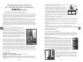
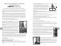
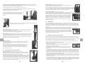
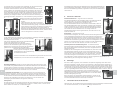
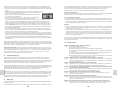
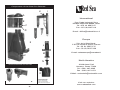
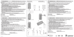
Installation and Operation Manual for Red Seas Prizm Pro Protein Skimmer GB TM 1. Introduction to Protein Skimming Protein skimming removes suspended or dissolved organic materials from the aquarium water by a mechanical process called foam fractionation. These materials consist of protein fragments and other waste, produced by the living organisms in the marine aquarium. Since these compounds are potentially harmful to the aquarium inhabitants, rapid removal is essential. The waste products are surface-active substances (surfactants), which collect at air/water surfaces in a one molecule thick layer. Inside a good Protein Skimmer a very large air-water contact area is created by blowing numerous fine air bubbles into the seawater. Protein molecules and other organic matter collect on the surface of these bubbles. As the protein covered bubbles rise to the water surface of the Skimmer, a protein rich foam is formed, which is pushed into the collection cup by the constant airflow. The great advantage of Protein skimming lies in the fact that as waste material is removed, it is separated from the water flow. In contrast, the particulate matter collected in a mechanical filter, stays in contact with the water flow and if not removed breaks down, increasing the organic loading of the aquarium. 2. The Prizm Principle of Operation The Prizm Pro Skimmer consists of 4 basic components; Main Body, Collection Cup, Inlet Pipe and Pump. It is designed to either hang-on the aquarium or to be installed next to or inside a sump. The Prizm Pro combines an efficient 18 blade Turbo air/water injector together with Red Sea's Patented convergent-divergent flow technology Reaction Chamber. Water and air are drawn into the skimmer through the Inlet Pipe by the 18 blade air/water mixer, which has been designed to generate the optimum ratio between the water/air flow rates, producing a constant stream of superfine air bubbles in a homogenous air/water mixture. The unique reaction chamber is divided into 2 compartments consisting of a convergent upward flow first stage, followed by a divergent downward flow second stage. The decreasing cross-sectional area of the convergent first stage, causes great turbulence and extended contact time between the air bubbles and water. The increasing cross-sectional area of the divergent second stage, causes the air bubbles to flow both co-andcounter-current before arriving to the water surface. The combined action of the 2 compartments creates a protein loaded, stable foam at the throat of the skimmer, positively pushing dry foam up into the collection cup. The bubble-trap under the reaction chamber redirects any escaping air bubbles ensuring that bubble free water is returned to the aquarium via the cascade. In addition, the bubble-trap acts as a Mechanical filter by trapping small particulate matter, thus removing it from the water flow. The Flow Regulator located on the Inlet Pipe allows the skimmers performance to be optimised for all aquarium conditions. 3. a. Do not operate any appliance if it has a damaged cord or plug, if it is malfunctioning, or if it is dropped or damaged in any manner. b. To avoid the possibility of the appliance plug or receptacle getting wet, position aquarium stand and tank to one side of a wall Power mounted receptacle to prevent water from dripping onto the Cord receptacle or plug. A "drip loop" shown in the figure, should be arranged by the user for each cord connecting an aquarium appliance to a receptacle. The "drip loop" is that part of the cord Aquarium below the level of the receptacle, or the connector. Use an extension cord if necessary, to prevent water traveling along the cord and coming into contact with the receptacle. If the plug or receptacle does get wet, DON'T unplug the cord. Disconnect the fuse or circuit breaker that supplies power to Drip Loop the appliance. Then unplug the device and examine for presence of water in the receptacle. c. Close supervision is necessary when any appliance is used by or near children. d. To avoid injury, do not contact moving parts. e. Always unplug an appliance from an outlet when not in use, before putting on or taking off parts, and before cleaning. Never yank cord to pull plug from outlet. Grasp the plug and pull to disconnect. f. Do not use an appliance for other than intended use. The use of attachments not recommended or sold by the appliance manufacturer may cause an unsafe condition. g. Do not install or store the appliance where it will be exposed to the weather or to temperatures below freezing. h. Make sure an appliance mounted on a tank is securely installed before operating it. i. Read and observe all the important notices on the appliance. j. If an extension cord is necessary, a cord with a proper rating should be used. A cord rated for less amperes or watts than the appliance rating may overheat. Care should be taken to arrange the cord so that it will not be tripped over or pulled. SAVE THESE INSTRUCTIONS 4. Assembly Instructions To prevent breakage during shipping the Prizm Pro comes unassembled. Before using, familiarize yourself with the components by assembling and disassembling the unit as described hereafter. To ensure watertight seals the parts are connected with o-rings. When assembling for the first time wet the o-rings with water of use a small amount of lubricant such as cooking oil. Inlet Pipe & Pump Assembly The pump is supplied ready for installation; however before use familiarize yourself with the pump assembly by disassembling and reassembling as described below. The Pump Cover is connected to the Pump Body with a bayonet connector, holding the inlet port in position. To remove the Cover, rotate counter clockwise and pull the cover away from the Body. The Inlet Port is positioned by 3 locators on the Body and sealed with an o-ring. To remove the Inlet Port simply pull away from the Body. The Rotor/Impeller assembly can be lifted out of the Pump Body. Reassemble; replace the Rotor/Impeller assembly, place the Inlet Port above the Pump Body ensuring that the 3 locators are positioned correctly and press down evenly. Place the Cover above the Inlet port, press the Cover to the Body while rotating the Cover clockwise. If you experience difficulty in rotating the Cover check that the Inlet Port is positioned correctly. Position 2 Safety IMPORTANT SAFETY INSTRUCTIONS WARNING - To guard against injury, basic safety precautions should be observed, including the following. READ AND FOLLOW ALL SAFETY INSTRUCTIONS DANGER - To avoid possible electric shock, special care should be taken since water is employed in the use of aquarium equipment. For each of the following situations, do not attempt repairs yourself; return the appliance to an authorized service facility for service or discard the appliance. 1 Position 1 In addition to being the water inlet, the Inlet Pipe houses the Air Inlet Tube and Flow Regulator. To attach the Inlet Pipe to the Pump; Place the Inlet Pipe above the Pump in Position 1 as shown in the diagram below aligning the arrows on the Inlet Pipe with those on the Cover. With small movements clockwise and counter clockwise of a few degrees, push the Inlet Pipe downwards and thereafter lock the Inlet Pipe in position by rotating it clockwise 90 degrees to position 2. 2 GB