1
English
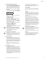
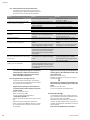
9.4 Enabling the parameter input mode
When the product is delivered, only the parameters in the menus 1.0x (menu select operational
mode) can be changed. It is not possible to change
parameters in any other menus. To be able to
make changes in those as well, you first have to
enable those menus.
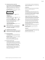
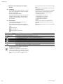
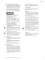
• Go to the default display by pressing the “go back”
or “go forward”
buttons.
P: 4.3bar H: cm
> automatic RW <
• Press the confirmation button
for about
10 seconds.
The display shows
> password * 00 * <.
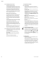
• Press the confirmation button
again in order
to change the second digit.
• Use the “go back”
and “go forward”
buttons to set the desired password.
• Press the confirmation button
in order to
confirm the entered password.
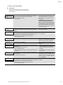
The display briefly shows
> select operational mode <.
The green LED flashes, indicating that you are in
parameter input mode.
NOTE: If no parameters are entered within five
minutes, the input mode will be disabled again
automatically. You can disable it manually by
entering the password 00.
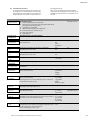
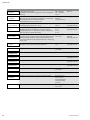
9.5 Configuration of the switchgear
NOTE: First read section 6 “Description of product
and accessories” and section 9.3. The assignment
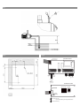
of levels to the various menus is shown in Fig. 4.
The selected tank form affects the indication of
the water level (see section 10.1). The tank form is
factory-set to standard.
Preparations
• Enable the switchgear using the password 01 for
parameter input (see section 9.4).
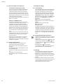
Tank height
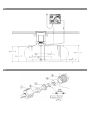
The height of the collector tank must be set for
correct functioning of the level indicator. For cylinders lying horizontally, for example, the height
corresponds to the cylinder diameter (see Fig. 4).
• Set the tank height in menu 2.05.
Height of the level sensor and the overflow
The height at which the level sensor and the overflow are fitted is specified as an absolute value to
the floor of the collector tank. Only the range
above the level sensor (menu 2.06) and below the
overflow (menu 2.07) is used to calculate the
water level. The areas beneath the sensor and
above the overflow cannot be used by the unit.
• The height at which the level sensor is fitted can
be viewed with menu 2.06.
NOTE: The height of the overflow must be above
the height of the level sensor and below the
height of the tank.
• Set the height of the overflow in menu 2.07.
Tank form
The exact water level is calculated on the basis of
your entries for the geometric shape (“form”) and
height of the collector tank.
• Select the tank form in menu 2.04.
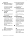
9.5.1 Setting the language
The switchgear is factory-set to German as the
menu language. You can change this to another
language as needed.
• Enable the switchgear using the password 01 for
parameter input (see section 9.4).
• Select the correct language in menu 2.02.
• Go back to the main menu via menu 2.99.
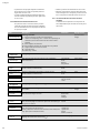
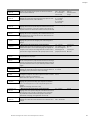
9.5.2 Setting the collector tank
The functioning of the unit must be adapted to
suit the particular collector tank. This means setting the shape of the tank (“tank form”), the tank
height, and the height of the overflow. After
entering the tank height (menu 2.05) and the
overflow level (menu 2.07) you can select either
the standard tank form or other tank forms
(square and rectangular, vertical cylinder, horizontal cylinder or spherical).
Installation and operating instructions RainSystem AF Comfort
29