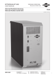
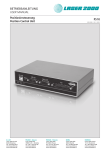
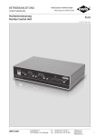
1
BETRIEBSANLEITUNG USER MANUAL Universal-Positioniersteuerung Universal Position Control Unit PS 90 9013.0180 / 21.11.2012 D-A-CH Laser 2000 GmbH 82234 Wessling Tel. +49 8153 405-0 [email protected] www.laser2000.de France – Telecom Laser 2000 SAS 78860 St-N. l. Bretèche Tel. +33 1 30 80 00 60 [email protected] www.laser2000.fr France – Photonic Laser 2000 SAS FR-33600 Pessac Tel. +33 5 57 10 92 80 [email protected] www.laser2000.fr Iberia Laser 2000 SAS 28034 Madrid Tel. +34 650 529 806 [email protected] www.laser2000.es Nordics Laser 2000 GmbH 112 51 Stockholm Tel. +46 8 555 36 235 [email protected] www.laser2000.se 1 Änderungen vorbehalten 2 Copyright reserved by OWIS (2006) Subject to change without notice Inhalt Content 1. Allgemeines..............................................................................5 2. Ausführung und Lieferumfang...................................................5 2.1 Standard..............................................................................5 2.2 Zubehör..............................................................................5 2.3 Optionen.............................................................................5 3. Sicherheit..................................................................................6 Ströme und Spannungen........................................................6 Erwärmung des Kühlkörpers bis max. 70° C............................6 4. Normen und Richtlinien.............................................................6 5. Technische Übersicht.................................................................6 6. Aufbau der Steuerung...............................................................7 Ein-/Aus-Taster.......................................................................7 Reset-Taster...........................................................................7 6.1 Anschlüsse..........................................................................8 USB- und RS-232-Schnittstelle................................................8 Anybus® -Schnittstelle............................................................8 NOT-AUS-Funktion.................................................................8 Stromversorgung....................................................................8 Universal-Motoranschluss......................................................8 End- und Referenzschalter......................................................8 Encodereingang.....................................................................9 6.2 Eingänge und Ausgänge......................................................9 7. Steuerungsarchitektur und Funktion........................................10 7.1 Aufbau..............................................................................10 Hauptplatine........................................................................10 Antriebsplatine....................................................................10 Motorplatine........................................................................10 Sicherungskonzept ..............................................................10 7.2 Betrieb unterschiedlicher Motortypen................................. 11 Schrittmotoren..................................................................... 11 DC-Motoren......................................................................... 11 BLDC-Motoren..................................................................... 11 7.3 Einstellelemente der Motorendstufe................................... 11 2-Phasen-Schrittmotor (Open Loop)...................................... 11 DC-Servomotor..................................................................... 11 7.4 Strombereichsumschaltung der Motorendstufe........................12 Vorwahl des Phasenstromes für 2-Phasen-Schrittmotoren.....12 Strombereichseinstellung für DC-Servomotoren.....................12 8. Steuerungsfunktionen.............................................................12 8.1 Trapezförmiges Punkt-zu-Punkt-Profil.................................12 8.2 S-Kurven-Punkt-zu-Punkt-Profil.........................................13 8.3 Geschwindigkeitsmodus....................................................13 8.4 Referenzierung..................................................................14 8.5 Linearinterpolation............................................................14 Begriffsbestimmung.............................................................14 Funktionsprinzip..................................................................14 8.6 Funktionsweise der allgemeinen Bahnsteuerung........................15 Definition.............................................................................15 Realisierung des Vektormodus..............................................15 Kreisinterpolation.................................................................16 9. Wegerfassung.........................................................................17 Encoder...............................................................................17 Linearmesssystem................................................................17 Auswertung des Linearmesssystems.....................................17 Lageregelung.......................................................................17 Funktionsweise der Nachlaufregelung..................................18 10. PID-Regelschleifenalgorithmus..............................................19 11. Positioniergeschwindigkeit und - beschleunigung, Berechnung.19 11.1 2-Phasen-Schrittmotor (Open Loop)..................................19 Allgemeines.........................................................................19 Periodendauer.....................................................................19 1. General Information................................................................44 2. Setup and Scope of Delivery....................................................44 2.1 Standard............................................................................44 2.2 Accessories........................................................................44 2.3 Options ............................................................................44 3. Safety.....................................................................................45 Currents and Voltages..........................................................45 Heat Sink Temperature up to 70° C max. .............................45 4. Standards and Directives.........................................................45 5. Technical Overview.................................................................45 6. Setup of the Control Unit........................................................46 On/Off Switch .....................................................................46 Reset Button........................................................................46 6.1 Connections......................................................................47 USB and RS-232 Interfases...................................................47 Anybus® Interface ..............................................................47 Emergency-Stop Function.....................................................47 Power Supply.......................................................................47 Universal Motor Connector .................................................47 Limit and Reference Switches...............................................47 Encoder Input .....................................................................48 6.2 Inputs and Outputs...........................................................48 7. Control Unit Architecture and Function....................................49 7.1 Assembly...........................................................................49 Main Board .........................................................................49 Drive Controller Board .........................................................49 Motor Driver Board..............................................................49 Safety Fuse Concept.............................................................49 7.2 Operation of Different Motor Types ...................................50 Step Motors.........................................................................50 DC Motors...........................................................................50 BLDC Motors.......................................................................50 7.3 Settings of the Motor Output Stage....................................50 2-Phase Step Motor (Open Loop)..........................................50 DC Servo Motor...................................................................50 7.4 Selection of the Current Range for the Motor Power Stage.51 Phase Current Setting for 2-Phase Step Motors..................... 51 Current Range Setting for DC Servo Motors.......................... 51 8. Control Functions ................................................................... 51 8.1 Trapezoidal Point-to-Point Profile....................................... 51 8.2 S-Curve Point-to-Point Profile............................................52 8.3 Velocity Mode...................................................................52 8.4 Reference run....................................................................53 8.5 Operating Mode of Linear Interpolation.............................53 Definition.............................................................................53 Functional Principle..............................................................53 8.6 Operation mode of the General Continuous Path Control...54 Definition.............................................................................54 Realisation of Vector Mode..................................................54 Circular interpolation............................................................55 9. Travel Measuring.....................................................................56 Encoder...............................................................................56 Linear Measuring System......................................................56 Evaluation of Linear Measuring Systems...............................56 Position Feedback Control....................................................56 Function of the follow up control..........................................57 10. PID Servo Loop Algorithm.....................................................58 11. Positioning Velocity and Acceleration, Calculation..................58 11.1 2-Phase Step Motor (Open Loop)......................................58 General Information.............................................................58 Cycle Time...........................................................................58 Subject to change without notice Betriebsanleitung-User Manual PS 90 Änderungen vorbehalten 3 Endgeschwindigkeit.............................................................19 Beschleunigung bei Trapezprofil...........................................20 11.2 DC-Servomotor und 2-Phasen-Schrittmotor (Closed-Loop).20 Allgemeines.........................................................................20 Abtastzeit............................................................................20 Endgeschwindigkeit.............................................................20 Beschleunigung bei Trapezprofil...........................................20 12. Nano-Hybrid-Ansteuerung.....................................................21 Allgemeines.........................................................................21 Technische Übersicht und Aufbau der Steuerung..................21 Sicherheit.............................................................................21 Steuerungsarchitektur und Funktion.....................................21 Anschluss............................................................................21 Positionierung im Nano-Hybrid-Betrieb................................21 Allgemeine Beschreibung der Nachlaufregelung für Piezo-Antriebe.22 13. Inbetriebnahme der PS 90......................................................23 13.1 Vorbereitung der Steuerung..............................................23 Aufstellung..........................................................................23 NOT-AUS-Funktion...............................................................23 13.2 Anschluss der Peripherie und Geräte................................23 13.3 Systemstart......................................................................23 Initialisierung.......................................................................23 Software..............................................................................23 14. Fehlerüberwachung...............................................................24 14.1 Endschalter......................................................................24 Funktion der Endschalter-Überwachung...............................24 Konfiguration der End- und Referenzschalter........................24 Wiederinbetriebnahme nach Achsenfehler............................24 14.2 Endstufen-Fehlerüberwachung.........................................24 14.3 Motion-Controller-Fehlerüberwachung.............................24 14.4 Time-Out-Überwachung..................................................24 15. Handterminal........................................................................25 15.1 Grundfunktionen des Handterminals................................25 Kurzbeschreibung der Menü-Ebenen....................................25 16. Joystick.................................................................................25 17. Hinweise zum Aufbau einer eigenen Applikationssoftware.....26 18. Befehlssatz der PS 90............................................................27 Final Velocity.......................................................................58 Acceleration for Trapezoidal Velocity Profiling.......................59 11.2 DC Servo Motor and 2-Phase Step Motor (Closed-Loop)...59 General Information.............................................................59 Servo Loop Cycle Time.........................................................59 Final Velocity.......................................................................59 Acceleration for Trapezoidal Velocity Profiling.......................59 12. Nano-Hybrid Control.............................................................60 General Information.............................................................60 Technical Overview and Setup of the Control Unit................60 Safety..................................................................................60 Control Architecture and Function........................................60 Connection..........................................................................60 Positioning in nano-hybrid mode..........................................60 General Description of Follow-up Control for piezo-drives.....61 13. Initial Operation of the PS 90 ................................................62 13.1 Installation and Preparing ...............................................62 Installation...........................................................................62 Emergency-Stop Function.....................................................62 13.2 Connection of Peripherals and Devices.............................62 13.3 Getting Started................................................................62 Initialization.........................................................................62 Software..............................................................................62 14. Malfunction Monitoring.........................................................63 14.1 Limit Switches..................................................................63 Working Principle of the Limit Switch Monitoring..................63 Configuration of Limit and Reference Switches.....................63 Reconnection after Axis Error...............................................63 14.2 Output-Stage Error Monitoring.........................................63 14.3 Motion-Controller Error Monitoring .................................63 14.4 Time-Out Monitoring ......................................................63 15. Hand-Held Terminal...............................................................64 15.1 Basic Functions of the Hand-Held Terminal.......................64 Short Description of the Menu Sections................................64 16. Joystick.................................................................................64 17. Instructions Concerning the Setup of an Own Application Software...65 18. Command Set for the PS 90 ..................................................66 Anhang I Befehlstabelle........................................................................28 II Relevanz der Parameter für verschiedene Motortypen...........38 III Belegungstabellen...............................................................39 TTL-Ein- /Ausgänge..............................................................39 Analog-Ein- /Ausgänge.........................................................39 SPS-Ein- /Ausgänge..............................................................39 RS-232.................................................................................39 Universal-Motorstecker........................................................40 Anschlusskabel....................................................................41 Wegmessystem/Encoder.......................................................41 Kabelvorschlag für RS-232-Schnittstelle................................41 Firmware-Update über RS-232-Schnittstelle..........................41 EU Konformitätserklärung........................................................81 Attachment: I Command Table....................................................................67 II Parameter Relevance for the different Motor Types................77 III Connecting Table.................................................................78 TTL In- / Outputs...................................................................78 Analog In- / Outputs.............................................................78 SPS In- / Outputs..................................................................78 RS-232.................................................................................78 Universal Motor Connector..................................................79 Connecting Cable................................................................80 Linear Measuring System/Encoder........................................80 Recommendation for a RS-232 Interface Cable.....................80 Firmware Update over the RS-232 Interface..........................80 UE Declaration of Conformity...................................................81 Änderungen vorbehalten 4 Betriebsanleitung-User Manual PS 90 Subject to change without notice 1. Allgemeines 2. Ausführung und Lieferumfang OWIS® Die Steuerung PS 90 ist eine universelle Positioniersteuerung, die für anspruchsvolle Steuerungsaufgaben eingesetzt wird. Sie ist modular aufgebaut und wird flexibel auf den jeweiligen Anwendungsbereich konfiguriert. Die PS 90 ist sehr leistungsstark und kann bis zu neun Achsen, mit Schrittmotoren, DC-, oder BLDC- Servomotoren in Kombination zu jeweils drei Achsen, oder bis zu sechs Nano-Hybrid-Achsen betreiben. Die in einem stabilen Metallgehäuse untergebrachte Steuerung kann eigenständig (Stand-Alone) oder mit einem Rechner betrieben werden. Für den Stand-Alone-Betrieb stehen ein Handterminal mit LC-Display und Folientastatur sowie ein Joystick zur Verfügung. Für die Kommunikation mit unterschiedlicher Peripherie sind zahlreiche Ein- und Ausgänge integriert, zum Beispiel:TTL/SPS/ Analog und PWM. Ist eine erhöhte Präzision gefordert, kann an jeder Achse ein zusätzliches Inkremental- oder Wegmesssystem angeschlossen werden (Option). Die Steuerung bietet außerdem die Möglichkeit, Schrittmotoren mit einem zusätzlichen Encoder im Closed-Loop-Modus zu betreiben. Bei Applikationen, für die höchste Präzision gefordert ist, können mit der PS 90 bis zu sechs Nano-Hybrid-Achsen betrieben werden. Die Hybrid-Technologie verbinden die Vorteile der spindelbetriebene Positionierung mit der Präzision von Piezo-Aktoren. Die PS 90 kann Punkt-zu-Punkt-Positionierbetrieb, Trapez- oder S-förmige Geschwindigkeitsprofile, sowie komplexe, mehrachsige Bahnsteuerungen, wie Linearinterpolation oder Kreisinterpolation, ausführen. Zum Lieferumfang der Steuerung gehört auch das Softwaretool OWISoft. Damit kann die PS 90 komfortabel konfiguriert und betrieben werden. OWIS® Positioniereinheiten sind in OWISoft hinterlegt und müssen nur dem jeweiligen Antrieb zugeordnet werden. Integration und Betrieb von Fremdmotoren ist ebenfalls möglich. Die PS 90 besteht aus einem Grundgerät für unterschiedliche Leistungen und Motorspannungen und wird entsprechend den Kundenanforderungen mit Achsmodulen, zusätzlichen Funktionen und Anschlüssen bestückt. Ein Nachrüsten mit Achsmodulen, Funktionen und Anschlüssen ist ebenso möglich. Das Gerät wird bei OWIS® komplett aufgebaut, getestet und anschlussfertig geliefert. Die gültige Firmware für die Steuerung ist eingespielt. Sie kann gegebenenfalls über die USB- oder RS-232-Schnittstelle aktualisiert werden. Zum Lieferumfang der Steuerung gehören: • PS 90 in der gewünschten Motorkonfiguration • Netzkabel mit 2,5 m Länge • USB-Kabel mit 2 m Länge • CD mit OWISoft und Dokumentation in Deutsch und Englisch • gedruckte Version der Betriebsanleitung in Deutsch und Englisch • Datenblatt in Deutsch und Englisch 2.1 Standard Die Steuerung verfügt über: • USB-Anschluss • RS-232-Anschluss • Anschluss für Handterminal • Anschluss für externen NOT-AUS-Taster • 4 Eingänge für Referenz- bzw. Endschalter je Achse • 4 TTL-Eingänge • 4 Analogeingänge • 4 TTL-Ausgänge • 4 Analogausgänge • Motoranschluss D-Sub 37-polig mit Anschluss für Motorhaltebremse (Option), End-/Referenzschalter und weitere Signale (siehe Pinbelegung, S.38) 2.2 Zubehör Folgendes Zubehör ist erhältlich: • Anschlusskabel mit Stecker für unterschiedliche Positioniersysteme • Joystick für drei Achsen, analog, mit 3 m Kabel • Handterminal mit LC-Display • NOT-AUS-Taster mit 3 m Kabel • Auswertung Wegmesssystem für 3 Achsen (Wegmessplatine) • Anschluss eines zusätzlichen Wegmesssystems/Encoder für eine Achse (siehe Kapitel „Anschlüsse“ S. 8) • Anschlusskabel mit Stecker für zusätzlichen Encoderanschluss • 4 zusätzliche TTL- und Analogeingänge • 4 zusätzliche TTL- und Analogausgänge • 8 zusätzliche SPS-Ein- und Ausgänge • 4 zusätzliche Ausgänge für Motor-Haltebremsen 2.3 Optionen Es sind folgende Optionen verfügbar: • Stand-Alone-Compiler mit USB-Dongle • Anybus®-Schnittstelle (Modbus/TCP) • Betrieb von BLDC-Servomotoren Subject to change without notice Betriebsanleitung-User Manual PS 90 Änderungen vorbehalten 5 3. Sicherheit 4. Normen und Richtlinien Die Steuerung hat je nach Ausführung ein Gewicht von etwa 15 kg. An der Frontseite unten befindet sich eine Griffmulde und an der Rückseite oben ein Handgriff. Damit kann die PS 90 sicher transportiert werden. Die Verwendung der PS 90 sollte ausschließlich von autorisiertem Fachpersonal und unter Berücksichtigung der Vorschriften der Unfallverhütung sowie den Vorschriften der Elektroindustrie durchgeführt werden. Beachten Sie hierzu auch die entsprechenden (im Datenblatt aufgeführten) Sicherheitshinweise. Nicht qualifizierte Personen dürfen die Steuerung nicht in Betrieb nehmen. Das Steuergerät ist für Betriebstemperaturen von + 10 bis + 40°C und Lagertemperaturen von - 10 bis + 50°C konzipiert. Es muss vor hoher Luftfeuchtigkeit, Erschütterungen sowie explosiven Gasen geschützt werden. Vor dem Öffnen des Gerätes muss es spannungsfrei geschaltet und von der Stromversorgung getrennt sein. Anschluss- und Montagearbeiten dürfen nur im stromlosen Zustand des Gerätes ausgeführt werden. Montage und Einsatz von Betriebsmitteln muss gemäß den Normen der Konformitätserklärung erfolgen. Die PS 90 hat eine NOT-AUS-Schaltung, deren Funktion an die EN 418 angelehnt ist. Sie unterbricht die Leistungsversorgung der Motorendstufen auf der Sekundärseite (Kleinspannungsbereich 24 V bzw. 48 V). Ferner wird der an einer Motorendstufe angeschlossene Motortyp über einen Codierwiderstand erkannt. So wird verhindert, dass ein versehentlich falsch angeschlossener Motortyp (z.B. ein DC-Motor an einer Schrittmotor-Endstufe) unkontrolliert losläuft. Die jeweiligen Achsmodule der Steuerungen dürfen nur mit den für sie konfigurierten Motortypen betrieben werden. Andere oder weiterführende Nutzungen entsprechen nicht dem vorgesehenen Verwendungszweck. Die Universal-Positioniersteuerung PS 90 erfüllt folgende Normen und Richtlinien: • RoHS-konform • CE-Richtlinie • EMV-Richtlinie 2004/108/EG • Niederspannungs-Richtlinie 2006/95/EG Ströme und Spannungen Das Schaltnetzteil der PS 90 besitzt einen Weitbereichseingang für eine Primärspannung von 100 bis 240 VAC. Der Netzeingang ist über eine Feinsicherung 10 AT (240 W) oder 16 AT (480 W) abgesichert. Ausgangsseitig sind keine besonderen Sicherheitsvorkehrungen erforderlich, da die PS 90 ausschließlich mit Kleinspannung (PELV) bis 48VDC arbeitet. Falls die PS 90 zur Ansteuerung von Nano-HybridAchsen konfiguriert ist, wird der Piezozweig mit Spannungen im Bereich von -71 V bis +71 V betrieben. Besondere Sicherheitshinweise finden Sie im Kapitel „Nano-Hybrid-Ansteuerung“. Erwärmung des Kühlkörpers bis max. 70° C Während des Betriebs der Steuerung wird die Abwärme der eingebauten Motorplatinen (Endstufen) über den seitlich angebrachten Kühlkörper an die Außenluft abgegeben. Je nach Anzahl und Größe (Stromaufnahme) der angeschlossenen Motoren, sowie der Betriebsart (Kurzzeit-, Aussetz-, Dauerbetrieb) erwärmt sich der Kühlkörper und kann eine Temperatur von maximal 70° C erreichen. Wärmestau in der Steuerung oder am Kühlkörper ist zu vermeiden. Es muss ein Mindestabstand von 15 cm zu geschlossenen Flächen und Wänden eingehalten werden. Bei Nichtbeachtung der Sicherheitshinweise der Betriebsanleitung sind Sachschäden sowie Personenschäden möglich. Daher müssen diese jedem Nutzer zugänglich gemacht und eingehalten werden. Die Universal-Positioniersteuerung PS 90 ist nach den anerkannten sicherheitstechnischen Regeln gebaut und erfüllt die im folgenden Kapitel aufgeführten Normen und Richtlinien. Änderungen vorbehalten 6 Störfestigkeit nach Fachgrundnorm EN 61000-6-1 mit: - Störfestigkeit gegen elektrostatische Entladung (ESD), Basisnorm: EN 61000-4-2 - Störfestigkeit gegen elektromagnetische Felder, Basisnorm: EN 61000-4-3 - Störfestigkeit gegen schnelle transiente Störgrößen (Burst), Basisnorm: EN 61000-4-4 - Störfestigkeit gegen Stoßspannungen (Surge), Basisnorm: EN 61000-4-5 Störaussendung nach Fachgrundnorm EN 61000-6-3 mit: - Störspannungen auf Netzleitungen, Basisnorm: EN 55014-1 (Hausgeräte) - Störstrahlung, Basisnorm: EN 55014-1 (Hausgeräte) - Grenzwerte für Oberschwingungsströme, Basisnorm: EN 61000-3-2 - Grenzwerte für Begrenzung von Spannungsänderungen, Spannungsschwankungen und Flicker, Basisnorm: EN 61000-3-3 5. Technische Übersicht Stromversorgung: Anzahl der Antriebe: Antriebsverband: Antriebsart: Kommunikation: Aufbau: Schutzart: Encoder: Dual-Encoder: Funktionen: Bewegungsabläufe: Betriebsanleitung-User Manual PS 90 Schaltnetzteil mit Strombegrenzung bis zu 9 Achsen (SM, DC und BLDC), bis zu 6 Nano-Hybrid-Achsen (SM) je 3 Achsen bilden einen koordinierten Antriebsverband, für eine Antriebsart 2-Phasen Schrittmotoren Open Loop (OL), 2-Phasen Schrittmotoren Closed-Loop (CL), DC-Servomotoren, BLDC-Servomotoren, Nano-Hybrid-Achsen USB 2.0, RS-232, optional Anybus®-Schnittstelle (Modbus/TCP) Tischgerät in hochwertigem Metallgehäuse IP 20 Quadratur-Signale A/B und Index, RS-422- oder TTL-Pegel, mit 4-fachAuswertung, max. Zählfrequenz 2 MHz (Signal) bzw. 8 MHz (Quadratur) Option zum Anschluss eines zweiten Encoders bzw. Wegmesssystems für Nachlaufregelung (sog. „Dual-Loop“). Auflösung 32 Bit, max. Zählfrequenz 5,5 MHz (Signal) Parametrierbare Beschleunigungsrampe ( / Bremsrampe), Dreieckiges- bzw. trapezförmiges Geschwindigkeitsprofil oder S-Kurve Punkt-zu-Punkt Positionierbetrieb und Linear- und Kreisinterpolation Subject to change without notice 6. Aufbau der Steuerung -Nr. Lüftungsschlitze Handterminal-Anschluss ® M1 F1 M2 F2 M3 RS-232-Schnittstelle EIN-Taster USB-Anschluss AUS-Taster F3 M4 F4 Anybus®-Schnittstelle M5 F5 M6 F6 M7 F7 Reset-Taster M8 PS 90 F8 M9 Griffmulde F9 Bild 1: Gehäuse Frontansicht Seriennummer TTL-Ein-/Ausgänge SPS-Ein-/Ausgänge Analog-Ein-/Ausgänge NOT-AUS-Anschluss Handgriff Lüftungsschlitze Ser.-Nr. Hauptschalter Netzansschluss M1 E1 F1 M2 E2 F2 M3 E3 F3 M4 E4 Anschlüsse für System-/Wegmess-Encoder F4 M5 E5 F5 M6 E6 F6 M7 E7 F7 M8 E8 F8 M9 E9 F9 1 2 3 4 5 6 7 8 9 Kühlkörper Sicherung Motorplatine Universal-Motoranschluss PS 90 Bild 2: Gehäuse Rückansicht Die PS 90 ist in einem hochwertigen und stabilen Metallgehäuse untergebracht. Zur internen Kühlung sind auf der Gehäusevorder- und Rückseite im oberen Bereich Lüftungsschlitze angebracht. Die Abwärme der eingebauten Motorplatinen (Endstufen) wird über den seitlich angebrachten Kühlkörper an die Außenluft abgegeben. Ein-/Aus-Taster Hauptschalter sowie Ein-/Aus-Taster der Steuerung sind beleuchtet. Die Beleuchtung des Hauptschalters zeigt die Aktivierung der Steuerungan. Die Taster werden nach dem Einschalten der EndstufenLeistungsversorgung durch Betätigung des Ein-Tasters zur Betriebskontrolle mit maximaler Intensität beleuchtet. Betätigung des AusTasters schaltet die Motorendstufen aus und reduziert die Hintergrundbeleuchtung der Taster auf ein Minimum. Subject to change without notice Ein- und Aus-Taster können geräteintern mittels Jumper aktiviert bzw. deaktiviert werden, um versehentliche Fehlbedienung zu verhindern. Ferner besteht die Möglichkeit, intern per Jumper eine Startautomatik zu aktivieren. Die Startautomatik bewirkt ein automatisches Einschalten der Endstufen etwa eine Sekunde nach Betätigung des Hauptschalters. Dies ist erforderlich, falls die PS 90 in einer Applikation eingesetzt wird, die eine manuelle Bedienung nicht erlaubt. Die Startautomatik ist standardmäßig aktiviert. Reset-Taster Falls die PS 90 nicht mehr reagiert oder unerwartete Fehler auftreten, kann der versenkte Reset-Taster z.B. mittels einer Kugelschreiberspitze betätigt werden. Alternativ ist es möglich, das Gerät aus- und wiedereinzuschalten. Betriebsanleitung-User Manual PS 90 Änderungen vorbehalten 7 6.1 Anschlüsse Die Anschlüsse der PS 90 befinden sich auf der Gehäusevorder- und auf der Gehäuserückseite. Dies sind Schnittstellen zur Kommunikation, Ein- und Ausgänge für Peripherie, sowie Anschlüsse für die Positionierer (siehe Bild 1 und 2). Anschluss USB-Slave Funktionen Kommunikation mit einem PC RS-232 Kommunikation mit einem PC RS-485 Buchse USB-Buchse Typ B D-Sub 9-poliger Stecker D-Sub 9-polige Buchse Analogeingänge 1, 2, 3 D-Sub 25-poliger Stecker D-Sub 25-poliger Stecker D-Sub 25-polige Buchse D-Sub 37-polige Buchse Fernbedienung der Steuerung mit dem Handterminal Joystick Manuelles Verfahren von maximal 3 Achsen TTL-Ein-/Ausgänge Interaktion mit externen Sensoren und Aktoren AnalogInteraktion mit externen Sensoren Ein-/Ausgänge und Aktoren, Joystick SPS-Ein-/Ausgänge Interaktion mit externer (SPS)-Steuerung UniversalMotorversorgung mit Anschlussstecker Motor-Haltebremse und Encoder-/Endschalteranschluss Wegmesssystem/ Anschluss von Wegmesssystemen CONNEI 12-polige Encoder Buchse Netzanschluss Spannungsversorgung Kaltgerätebuchse Option: Anybus®-Modul Modbus/TCP Kommunikation mit einem PC über Ethernet RJ 45 USB- und RS-232-Schnittstelle Die PS 90 hat eine USB 2.0-Slave-Schnittstelle, der Anschluss befindet sich auf der Geräterückseite. Die Schnittstelle ist USB 1.1 und 2.0 kompatibel. Die USB-Schnittstelle der PS 90 ist als sogenannte COM-Brücke realisiert. Der Windows-Gerätetreiber erkennt die PS 90 als „USB-Serial-Port“ und weist ihr eine COM-Portnummer zu, die vom Anwender bei Bedarf verändert werden kann. Die USB-Schnittstelle wird nach erfolgreicher Installation als virtuelle RS-232-Schnittstelle angesprochen. Alternativ zur USB-Schnittstelle kann die Steuerung über die RS-232 mit einem PC kommunizieren. Die PS 90 kann mit Übertragungsraten von 9 600, 19 200, 38 400, 57 600 oder 115 200 Baud arbeiten. Es ist unbedingt darauf zu achten, dass die Übertragungsrate der PS 90 mit der im Gerätetreiber eingestellten Übertragungsrate übereinstimmt, sonst ist keine Kommunikation möglich. Voreinstellung ist 9 600 Baud. (Kann aus dem Abnahmeprotokoll entnommen werden.) Anybus® -Schnittstelle Die PS 90 kann optional mit einer Anybus®-Modul „Modbus/TCP“ geliefert werden. Mit diesem Modul ist es möglich, über Ethernet Kommandos zur PS 90 zu schicken und entsprechende Rückmeldungen zu erhalten. NOT-AUS-Funktion An der Geräterückseite ist ein Anschluss für einen externen NOT-AUS-Taster vorgesehen, an welchem standardmäßig ein Kurzschlussstecker eingesteckt ist. Soll ein NOT-AUS-Taster angeschlossen werden, ist der Kurzschlussstecker zu entfernen. Änderungen vorbehalten 8 ! Hinweis: Wird der Kurzschlussstecker entfernt und kein NOT‑AUS-Taster angeschlossen, ist die Funktion der Motorplatinen (Motorendstufen) blockiert. Die NOT-AUS-Schaltung der PS 90 ist angelehnt an die EN 418 und unterbricht die Leistungsversorgung der Motorendstufen auf der Sekundärseite (Kleinspannungsbereich 24 V oder 48 V). Die Funktion wird durch ein selbsthaltendes Relais mit zwangsgeführten Kontakten (2 Öffnerkontakte in Reihe) umgesetzt. Bei Abschaltung der Endstufen wird zusätzlich zur Endstufenversorgung die Endstufenfreigabe weggeschaltet (doppelte Sicherheit). Stromversorgung Die Stromversorgung der PS 90 ist für eine Eingangsspannung von 100 VAC bis 240 VAC mit 50/60 Hz ausgelegt (Weitbereichseingang). Ein Schaltnetzteil generiert 24 VDC und versorgt die Ein- und Ausgänge auf der Hauptplatine. Die Logikspannungen + 5 V, + 2,5 V und + 3,3 V für Haupt- und Antriebsplatine werden aus dieser 24 VDC-Versorgung erzeugt. Ein zweites Schaltnetzteil generiert die Zwischenkreisspannung für die Motorplatinen (wahlweise 24 oder 48 VDC). Diese Spannung speist die Leistungsendstufen der Motorplatinen. Die Versorgungsspannungen für Logik und Leistung sind galvanisch getrennt. Universal-Motoranschluss Mit dem passenden OWIS® Anschlusskabel werden die OWIS® Positioniereinheiten angeschlossen. Über diesen Anschluss stecker wird der Motor mit Leistung versorgt, die Signale des Encoders und der Endschalter übertragen, sowie die Motor-Haltebremse, falls vorhanden, gesteuert. Die Endstufe hat eine zusätzliche Schutzeinrichtung, die dafür sorgt, dass ein versehentlich falsch angeschlossener Motortyp (z.B. ein DC-Motor an einer Schrittmotor-Endstufe) nicht unkontrolliert startet. Am Motoranschlusskabel ist zwischen Pin 14 und Pin 15 ein Widerstand zur Codierung des Motortyps eingebaut. Codierung: • 0 Ohm: DC-Servomotor • Widerstand unendlich: 2-Phasen-Schrittmotor • 470 Ohm: BLDC Beim Einschalten misst die Steuerung den Widerstandswert und signalisiert einen Fehler, wenn der gemessene Wert nicht zu der jeweiligen Steuerplatine passt. Die Fehlermeldung der Endstufe wird über das Kommando „?ASTAT“ ausgelesen (siehe Befehlssatz ab S. 26). Der Steckerbelegungsplan ist im Anhang aufgeführt. Die Belegung entspricht dem OWIS®-Standard. End- und Referenzschalter Pro Achse können maximal 4 Schalter angeschlossen werden. Dies können 24 V-Induktivschalter, Mikroschalter, TTL-Hall-EffektEndschalter oder TTL-Lichtschranken sein. An die Eingänge können beliebige Pegel, ± 5 V – ± 24 V, Öffner oder Schließer, gegen + Ub oder Masse schaltend, angeschlossen werden. Einer der vier Schalter ist zusätzlich als Referenzschalter definiert. Der aktive Pegel und die Zuordnung der Schalter werden per Software konfiguriert. Betriebsanleitung-User Manual PS 90 Subject to change without notice Encodereingang Der Encodereingang ermöglicht sowohl den Anschluss von Encodern mit Leitungstreibern (antivalente Signale für CHA, CHB und optional Index I), als auch von Encodern mit TTL-/CMOS-Signalen. Folgende Eingangssignale sind definiert: Versorgung Kanal Kanal Kanal Kanal Kanal Kanal schaltend. Sie können induktive Lasten ansteuern, die kurzzeitig einen hohen Anzugsstrom und anschließend nur noch einen geringen Haltestrom brauchen, wie Haltebremsen oder Hubmagnete. Die Leistungsausgänge können als Haltebremsenansteuerung konfiguriert werden. Die NOT-AUS-Schaltung der PS 90 ist angelehnt an die EN 418 und unterbricht die Leistungsversorgung der Motorendstufen auf der Sekundärseite (Kleinspannungsbereich 24 V oder 48 V). Die Funktion wird durch ein selbsthaltendes Relais mit zwangsgeführten Kontakten (2 Öffnerkontakte in Reihe) umgesetzt. Bei Abschaltung der Endstufen wird zusätzlich zur Endstufenversorgung die Endstufenfreigabe weggeschaltet (doppelte Sicherheit). Vcc (+ 5 V); GND A (TTL oder CMOS) A invertiert B (TTL oder CMOS) B invertiert I (TTL oder CMOS) I invertiert Die Umsetzung der antivalenten Signale auf TTL-Signale erfolgt mit RS-422-Leitungsempfängern. Schließt man einen Encoder mit TTL-/CMOS-Signalen an, so bleibt der Eingang für das invertierte Signal offen und wird intern mit einem hochohmigen Spannungsteiler auf 1,4 V gezogen. Die Leiterbahnen der invertierten Signale haben geräteintern auf den Antriebsplatinen Trennstellen mit beidseitigen Überbrückungs-Pads, um eine Unterbrechung der invertierten Signalleitungen zu ermöglichen, falls dies erforderlich sein sollte. Am nichtinvertierenden Eingang ist ein Pullup-Widerstand nach + 5 V vorgesehen. 6.2 Eingänge und Ausgänge Zur Interaktion mit externen Sensoren und Aktoren sind entsprechende digitale und analoge Ein- und Ausgänge vorgesehen. An die TTL-kompatiblen Eingänge können einfache Gabellichtschranken etc. angeschlossen werden. Mit den TTL-Ausgängen ist es möglich, digitale Hardware in der Anwendung direkt anzusteuern. Die SPS-kompatiblen Eingänge ermöglichen die Verwendung der im Anlagenbau üblichen 24 VDC-Induktiv-Sensoren in Zweidraht- und Dreidraht-Technik. Die Arbeitswiderstände der SPS-Eingänge können per Software gemeinsam als Pull-Up oder Pull-Down geschaltet werden. Die SPS-Ausgänge steuern Magnetventile oder sonstige induktive und ohmsche Lasten direkt an (gegen + 24 V schaltend). Die Ausgänge sind kurzschlussfest. Eigenschaften Pegel TTL-Eingänge SPS-Eingänge Analogeingänge TTL-Ausgänge SPS-Ausgänge Analogausgänge Leistungsausgänge 0-5 V 0-24 VDC 0-4,096 VDC 0-5 V 0-24 VDC 0-4,096 VDC 0-24 VDC Strom Sonstiges 10 mA 300 mA 10 mA 1,0 A — 2-Draht/3-Draht Auflösung 10 Bit — kurzschlußfest Auflösung 10 Bit PWM Die analogen Eingänge können Spannungen zwischen 0 V und 4,096 V direkt messen und mit 10-Bit-Auflösung wandeln (Referenzspannung: 4,096 V). Die Ein- und Ausgänge sind nicht galvanisch getrennt. Die Abfragebefehle „?ANIN<uv>“ und „?INPUTS“ beziehen sich auf dieselben Eingänge der PS 90 (siehe Befehlssatz ab S. 26). Die Auswertung der Eingänge erfolgt entweder analog oder digital. Die vier Leistungsausgänge sind pulsweitenmoduliert und nach Masse Subject to change without notice Betriebsanleitung-User Manual PS 90 Änderungen vorbehalten 9 7. Steuerungsarchitektur und Funktion den Antriebsplatinen, verwaltet die digitalen und analogen Ein- und Ausgänge und kommuniziert mit dem Handterminal. 1 2 3 4 Bild 3: Gehäuse Seiten- und Innenansicht Die Hauptplatine hat einen USB-Anschluss für die Kommunikation mit einem PC. Eine weitere RS-232-Schnittstelle ist als alternative Kommando-Schnittstelle zum PC implementiert. Über die USB- oder RS-232-Schnittstelle ist auch ein Update der Firmware möglich. Über die RS-485-Schnittstelle wird das Handterminal angeschlossen. Mit dem optionalen Anybus®-Modul „Modbus/TCP“ ist die Kommunikation mit einem PC über Ethernet möglich. Antriebsplatine Jede Antriebsplatine beinhaltet ferner einen Motion-Prozessor, der drei Achsen steuern bzw. regeln kann. Der Motion-Prozessor verarbeitet die Befehle des Mikrocontroller und generiert entsprechend die Ansteuersignale für die Endstufenmodule. Die Schnittstelle zu den Endstufen ist mittels Optokoppler galvanisch getrennt. Wird ein zweites Wegmesssystem zur Nachlaufregelung verwendet (Option), muss eine entsprechende Wegmessplatine auf der Antriebsplatine aufgesteckt werden. Motorplatine Die Steuerung besteht im Wesentlichen aus folgenden Komponenten: 1. ein eingebautes Netzteil 2. eine Hauptplatine 3. max. 3 Antriebsplatinen 4. max. 9 Motorplatinen (Endstufen) 7.1 Aufbau 4 1 Bild 6: Funktion Antriebsplatine mit Motorplatine Die PS 90 kann mit maximal neun Motorplatinen bestückt werden. Auf der Motorplatine befindet sich die Endstufe, die die Wicklung(en) des Motors mit Strom versorgt und damit das Drehmoment steuert. Die Motorplatine ist mit dem Universal-Anschlussstecker verbunden, an dem der Motor mit seinen Wicklungen, der Encoder, evtl. die Hall-Effekt-Kommutierungssensoren und alle Schalter, die zu dieser Antriebsachse gehören, angeschlossen sind. Bild 4: Steuerungsarchitektur Hauptplatine Sicherungskonzept Für jede Motorplatine ist eine eigene Schmelzsicherung (5 x 20 mm) vorhanden, die entsprechend dem maximal auftretenden Strom ausgelegt ist. Sie soll helfen, im Falle eines Hardwaredefektes größeren Schaden zu vermeiden. Die Sicherung ist von der Geräterückseite zugänglich und kann von außen getauscht werden. Standardmäßige Absicherung: 6,3 AT. Bild 5: Steuerungsarchitektur Hauptplatine Die Hauptplatine ist das Kernstück der PS 90. Sie übernimmt die Steuerung des Hauptablaufs, kommuniziert mit dem PC und mit Änderungen vorbehalten 10 Betriebsanleitung-User Manual PS 90 Subject to change without notice 7.2 Betrieb unterschiedlicher Motortypen Schrittmotoren Die PS 90 ist für den Betrieb von 2-Phasen-Schrittmotoren ausgelegt, die sowohl gesteuert (Open Loop), als auch geregelt (Closed-Loop) betrieben werden können. DC-Motoren Die PS 90 kann ebenfalls DC-Motoren (bürstenbehaftete Servomotoren) ansteuern. Die Endstufe ist als H-Brücke mit Strombegrenzung ausgeführt, die mit einem PWM-Signal und einem Richtungssignal angesteuert wird. Es ist eine automatische Strombegrenzung eingebaut, die beim Überschreiten des maximalen Motorstroms anspricht. BLDC-Motoren Ein Betrieb von BLDC-Motoren (bürstenlose Servomotoren) mit drei Motorphasen ist auch möglich. Die Endstufe steuert drei Motorwicklungen mit drei vom Motion-Controller generierten 50/50-PWM-Signalen an. In allen 3 Brückenzweigen wird der Summenstrom gemessen. Treten zu hohe Motorströme auf, so wird der Strom mittels Stromchopper begrenzt. 7.3 Einstellelemente der Motorendstufe • 4-fach-Dipschalter S1, S2 • Jumper JP10 und JP11 2-Phasen-Schrittmotor (Open Loop) JP10 und JP11 müssen sich in Stellung 2 befinden. Beide Jumpereinstellungen dürfen unter keinen Umständen verändert werden! Die Vorwahl einer Strombegrenzung ist nicht möglich. Vorwahl von PWM-Chopper-Betriebsmodus und -Zeitkonstante mittels DIP-Schalter S1: S1 4-3-2-1 1-1-1-1 1-1-1-0 1-1-0-1 1-1-0-0 1-0-1-1 PWM-Modus Schnellentregung aus Schnellentregung ein, Timing kurz, bei Vorzeichenwechsel Schnellentregung ein, Timing lang, bei Vorzeichenwechsel Schnellentregung ein, Timing kurz, fester Rhythmus Schnellentregung ein, Timing kurz, fester Rhythmus Die Einstellung des PWM-Choppermodus beeinflusst das Geräuschverhalten der Endstufe bei ruhendem und drehendem Motor, sowie die Drehmomentcharakteristik des Motors, insbesondere bei hohen Drehzahlen. Die Standardeinstellung ist in obiger Tabelle grau markiert und sollte in den meisten Anwendungsfällen ein optimales Ergebnis liefern. Wir empfehlen, die werksseitige Voreinstellung nicht zu ändern. DC-Servomotor JP10 und JP11 müssen sich in Stellung 3 befinden. Beide Jumpereinstellungen dürfen unter keinen Umständen verändert werden! Vorwahl der Strombegrenzung für Strombereich 1 (I max=4,65 A) bzw. Strombereich 2 (I max=7,15 A) mittels DIP-Schalter S2: S2 4-3-2-1 1-1-1-1 1-1-1-0 1-1-0-1 1-1-0-0 1-0-1-1 1-0-1-0 1-0-0-1 1-0-0-0 0-1-1-1 0-1-1-0 0-1-0-1 0-1-0-0 0-0-1-1 0-0-1-0 0-0-0-1 0-0-0-0 Strombereich 1 Strombegrenzung 0,15 A 0,45 A 0,75 A 1,05 A 1,35 A 1,65 A 1,95 A 2,25 A 2,55 A 2,85 A 3,15 A 3,45 A 3,75 A 4,05 A 4,35 A 4,65 A Strombereich 2 Strombegrenzung 0,34 A 1,01 A 1,70 A 2,39 A 3,06 A 3,74 A 4,43 A 5,11 A 5,79 A 6,47 A 7,15 A (7,84 A) (8,51 A) (9,20 A) (9,88 A) (10,6 A) Die Werte in Klammern ( ) sind für die Standardversion der Motorendstufe nicht zulässig. Bild 7: Werkseitige Dipschalter- und Jumpervoreinstellungen OFF ^ =0 1 2 3 4 Bild 8: DIP-Schalter S1, S2, S3 ON ^ =1 O N Vorwahl der PWM-Chopper-Zeitkonstante mit DIP-Schalter S1-1: S1 4-3-2-1 1-1-1-1 1-1-1-0 Schnellentregung aus ein Die Standardeinstellung ist in obiger Tabelle grau markiert und sollte in den meisten Anwendungsfällen ein optimales Ergebnis liefern. Wir empfehlen, die werksseitige Voreinstellung nicht zu ändern. Subject to change without notice Betriebsanleitung-User Manual PS 90 Änderungen vorbehalten 11 Die PS 90-Endstufe besitzt zwei umschaltbare Strombereiche, um möglichst hohe Auflösung der Stromeinstellung bzw. möglichst feinen Mikroschrittbetrieb zu ermöglichen. Der gewählte Strombereich wird im statischen RAM abgespeichert. Um den neuen Strombereich zu aktivieren, ist es erforderlich, die Achse <n> nach der Bereichsumschaltung neu zu initialisieren. Vorwahl von Strombereich 2 (hoch) für Achse <n> erfolgt über folgende Kommandofolge: AMPSHNT<n>=1 INIT<n> Zurückschalten in Strombereich 1 (niedrig) kann mittels folgender Befehlssequenz vorgenommen werden: AMPSHNT<n>=0 INIT<n> Zeit t –D A D Zeit t ! Es sollte generell der kleinstmögliche Strombereich gewählt werden, um eine optimale Mikroschrittauflösung zu erhalten. Strombereichseinstellung für DC-Servomotoren Für DC-Servomotoren ist der geeignete Strombereich unter Berücksichtigung des thermisch zulässigen Dauerstroms des jeweiligen Motortyps vorzuwählen. Eine Strombegrenzung kann im Inneren des Gerätes per Dipschalter auf der jeweiligen Motorplatine konfiguriert werden. (Weitere Hinweise sind im Kapitel „Einstellelemente der Motorendstufe” zu finden.) 8. Steuerungsfunktionen 8.1 Trapezförmiges Punkt-zu-Punkt-Profil Die folgende Tabelle umfasst die spezifischen Profilparameter für den trapezförmigen Punkt-zu-Punkt-Modus: Bereich -2.147.483.648…+2.147.483.647 Counts (1…2.147.483.647)/65.536 Counts/Cycle (1…2.147.483.647)/65.536 Counts/Cycle² (1…2.147.483.647)/65.536 Counts/Cycle² Geschwindigkeit v Bild 10: Trapez-Kurven Profil, A = Beschleunigung, D = Verzögerung Hinweis: Alle Strombereich 2 darf bei der Standardversion der Endstufe maximal ein Phasenstrom von 3,6 A, entsprechend 66% des Endwerts, eingestellt werden. Änderungen vorbehalten D Bild 9: A = Beschleunigung, D = Verzögerung Geschwindigkeit v Fahrstrom: DRICUR<n>=<uv> Haltestrom: HOLCUR<n>=<uv> Maximaler Phasenstrom Strombereich 1 (entsprechend 100%): 2,4 A Maximaler Phasenstrom Strombereich 2 (entsprechend 100%): 5,45 A 12 A –A Vorwahl des Phasenstromes für 2-Phasen-Schrittmotoren Für 2-Phasen-Schrittmotoren können Fahrstrom und Haltestrom separat voreingestellt werden. Die Einstellung für Achse <n> kann wie nachfolgend beschrieben vorgenommen werden. Die Angabe <uv> erfolgt als ganzzahliger Prozentwert des Maximalstromes im vorgewählten Strombereich (1 oder 2). Profilparameter Format Wortlänge Position 32.0 32 bit Geschwindigkeit 16.16 32 bit Beschleunigung 16.16 32 bit Verzögerung 16.16 32 bit Für dieses Profil errechnet der Host eine Beschleunigung, eine Verzögerung, eine Geschwindigkeit und eine Endposition. Das Profil ist nach der Kurvenform (Bild 9, 11) benannt: Die Achse beschleunigt linear (anhand des programmierten Beschleunigungs wertes), bis sie die programmierte Geschwindigkeit erreicht. Die Achse bremst dann linear ab (den Verzögerungsgswert nutzend), bis sie an der vorgegebenen Position stehen bleibt. Falls die programmierte Fahrdistanz so kurz ist, dass die Verzögerung einsetzen muss, bevor die Achse die programmierte Geschwindigkeit erreicht, wird das Profil keinen konstanten Geschwindigkeitsbereich aufweisen, und das Trapez wird zum Dreieck (Bild 10). Geschwindigkeit v 7.4 Strombereichsumschaltung der Motorendstufe Geschwindigkeit ändern Zielposition ändern A D Richtungsumkehr D -A Zeit t -D Bild 11: A = Beschleunigung, D = Verzögerung Die Beschleunigungs- und Verzögerungsrampen können symmetrisch (wenn die Beschleunigung gleich der Verzögerung ist) oder asymmetrisch sein (wenn die Beschleunigung nicht gleich der Verzögerung ist). Der Beschleunigungsparameter wird immer am Anfang der Bewegungssequenz benutzt. Danach wird der Wert für die Beschleunigung in dieselbe Richtung verwendet, und der Wert für die Verzögerung wird in entgegengesetzter Richtung eingesetzt. Falls keine Bewegungsparameter während der Bewegungssequenz verändert werden, wird der Beschleunigungswert verwendet bis die maximale Geschwindigkeit erreicht wurde. Der Verzögerungswert wird für die Abbremsrampe eingesetzt, bis die Geschwindigkeit auf Null sinkt. Es ist möglich, einen der Profilparameter zu verändern, während die Achse sich in diesem Profilmodus befindet. Der Profilgenerator wird immer versuchen, die Bewegung innerhalb der durch die Parameter vorgegebenen gesetzten Bedingungen auszuführen. Wird während der Bewegung die Endposition in solch einer Weise verändert, dass die restliche Fahrdistanz das Vorzeichen wechselt, wird die PS 90 mit Rampe bis zum Stopp abbremsen und dann in entgegengesetzte Richtung beschleunigen, um sich zu der neuen angegebenen Position zu bewegen. Betriebsanleitung-User Manual PS 90 Subject to change without notice 8.2 S-Kurven-Punkt-zu-Punkt-Profil Die folgende Tabelle fasst die Profilparameter für den S-Kurven-Punkt-zu-Punkt-Modus zusammen: -2.147.483.648…+2.147.483.647 Counts (1…2.147.483.647)/65.536 Counts/Cycle (1…2.147.483.647)/65.536 Counts/Cycle² (1…2.147.483.647)/65.536 Counts/Cycle² (1…2.147.483.647)/4.294.967.296 Counts/Cycle³ Das S-Kurven-Punkt-zu-Punkt-Profil fügt im Vergleich zum Trapezprofil einen weiteren Parameter („Jerk“ oder „Ruck“) hinzu. Dieser gibt die Änderungsrate der Beschleunigung an. Wenn in diesem Profilmodus eine Positionierung durchgeführt wird, wird zunächst die Beschleunigung linear mit dem eingestellten Wert Jerk erhöht, bis sie den programmierten Wert erreicht. Der Übergang von konstanter Beschleunigung zu konstanter Geschwindigkeit erfolgt ebenfalls mit einem linearen Anwachsen der Verzögerung. Das Verhalten am Ende der Bewegung ist analog dazu. Im S-Kurven-Profilmodus muss der gleiche Wert sowohl für die Beschleunigungs- als auch für die Verzögerunsrampe benutzt werden. Asymmetrische Profile sind nicht erlaubt. Dies ist nur im trapezförmigen Profilmodus möglich. Geschwindigkeit v I II III –J Segmente IV A J V –J VI VII Geschwindigkeit v Bereich Segmente IV III V –J J VII –J A D J Zeit t Bild 13: S-Kurve erreicht nicht die maximale Beschleunigung, A = Beschleunigung, D = Verzögerung, J = Beschleunigungsänderung Falls eine Position derart angegeben wird, dass die Endgeschwindigkeit nicht erreicht werden kann, wird es kein Segment IV geben (siehe Bild 14). I Geschwindigkeit v Profilparameter Format Wortlänge Position 32.0 32 bit Geschwindigkeit 16.16 32 bit Beschleunigung 16.16 32 bit Verzögerung 16.16 32 bit Jerk 0.32 32 bit I –J III Segmente V –J J VII J Zeit t Bild 14: S-Kurve ohne maximales Geschwindigkeitssegment, A = Beschleunigung, D = Verzögerung, J = Beschleunigungsänderung Im Gegensatz zum trapezförmigen Profilmodus erlaubt der S-KurvenProfilmodus keine Änderungen an einem der Profilparameter, während die Achse in Bewegung ist. Ebenfalls darf die Achse nicht in den S-Kurven-Modus geschaltet werden, während die Achse in Bewegung ist. Es ist allerdings erlaubt, vom S-Kurven-Modus zu einem anderen Profilmodus während der Bewegung zu wechseln. 8.3 Geschwindigkeitsmodus D J Zeit t Bild 12: S-Kurven Profil, A = Beschleunigung, D = Verzögerung, J = Beschleunigungsänderung Bild 12 zeigen ein typisches S-Kurven-Profil. In Segment I erhöht sich der Beschleunigungswert um den per Jerk gesetzten Wert, bis die maximale Beschleunigung erreicht wurde. Im nächsten Segment wird die Achse linear (Jerk = 0) beschleunigt. Das Profil wendet dann im Segment III den negativen Wert des Jerks an, um die Beschleunigung zu reduzieren. Im Segment IV verfährt die Achse jetzt mit maximaler (programmierter) Geschwindigkeit (V). Das Profil wird dann in einer dem Beschleunigungswert ähnlichen Weise abbremsen, indem in umgekehrter Richtung der negative Jerk verwendet wird, um zuerst die maximale Verzögerung zu erreichen (A), und dann die Achse zu einem Halt an der Endposition zu bringen. Ein S-Kurven-Profil enthält u.U. nur einen Teil der in Bild 12 gezeigten Segmente. Dies kann z.B. der Fall sein, wenn nicht die maximale Beschleunigung vor dem „Halbweg“ in Richtung Endgeschwindigkeit oder Endposition erreicht werden kann. Hier würde das Profil dann nicht die Segmente II und VI enthalten (siehe Bild 13). Die folgende Tabelle fasst die Profilparameter für den Geschwindigkeitsmodus zusammen: Profilparameter Format Wort- Bereich länge Geschwindigkeit 16.16 32 bit (-2.147.483.648…+2.147.483.647) /65.536 Counts/Cycle Beschleunigung 16.16 32 bit (1…2.147.483.647)/65.536 Counts/Cycle² Verzögerung 16.16 32 bit (1…2.147.483.647)/65.536 Counts/Cycle² Im Gegensatz zu den trapezförmigen und S-Kurven-Profilmodi, bei denen die Endposition bestimmt, ob positive oder negative Geschwindigkeit vorgegeben wird, bestimmt das Vorzeichen des im Geschwindigkeitsmodus übergebenen Geschwindigkeitswerts, ob in positiver oder negativer Richtung gefahren werden soll. Deswegen kann der Geschwindigkeitswert der zur PS 90 übermittelt wird, positive Werte (für positive Bewegungsrichtung) oder negative Werte (für entgegengesetzte Bewegungsrichtung) annehmen. Bei diesem Profil wird keine Endposition angegeben. Die Bahn wird ausgeführt, indem die Achse mit dem angegebenen Wert kontinuierlich beschleunigt, bis die jeweilige Endgeschwindigkeit erreicht wird. Die Achse fängt an abzubremsen, wenn eine neue Geschwindigkeit angegeben wird, die einen kleineren Wert hat als die aktuelle Geschwindigkeit oder ein anderes Vorzeichen hat als die aktuelle Richtung vorgibt. Ein einfaches Geschwindigkeitsprofil sieht aus wie ein einfaches trapezförmiges Punkt-zu-Punkt-Profil, wie in Bild 9 dargestellt. Subject to change without notice Betriebsanleitung-User Manual PS 90 Änderungen vorbehalten 13 Bild 15 zeigt ein komplizierteres Profil, in dem beides, die Geschwindigkeit als auch die Bewegungsrichtung, zweimal wechseln. Bild 15: Geschwindigkeitsprofil ! Hinweis: Im Geschwindigkeitsmodus ist die Achsenbewegung nicht an eine Endposition gebunden. Es liegt in der Verantwortung des Anwenders, Geschwindigkeits- und Beschleunigungswerte zu verwenden, die einen sicheren Bewegungsablauf garantieren. 8.4 Referenzierung Geschwindigkeit v Bei der Referenzfahrt wird einer der vier Endschalter angefahren. Die Position kann an dieser Stelle genullt werden. Dazu werden zwei Referenzfahrtgeschwindigkeiten mit Betrag und Vorzeichen und eine Referenzbeschleunigung parametriert. Der Endschalter wird mit großer Geschwindigkeit angefahren und mit kleiner Geschwindigkeit verlassen, dann wird gestoppt. A -A -D Bild 16: Referenzfahrt, A = Beschleunigung, D = Verzögerung D Zeit t 8.5 Linearinterpolation Begriffsbestimmung Linearinterpolation bezeichnet hier die Synchronisation der Bewegung aller beteiligten Achsen derart, dass die Achsen quasi-simultan starten und ihre Ziele praktisch gleichzeitig erreichen. Die Bewegung erfolgt hierbei mittels trapezförmiger Geschwindigkeitsprofile, wobei die Beschleunigungs- und Bremsrampen so angepasst werden, dass alle Achsen ebenfalls synchron beschleunigen bzw. bremsen. Die Bewegung eines aus Linearachsen bestehenden XYZ-Systems, das über Linearinterpolation angesteuert wird, beschreibt somit im kartesischen Koordinatensystem näherungsweise eine Gerade im Raum. Die Achse mit der niedrigsten Achsnummer, welche den längsten Verfahrweg (umgerechnet in Inkremente) zurückzulegen hat, wird als Führungsachse f bezeichnet. Auf diese Achse werden die restlichen an der Linearinterpolation beteiligten Achsen steuerungsintern per Software synchronisiert. Funktionsprinzip Welche der maximal 9 Achsen an der Linearinterpolation beteiligt sind, wird über einen Binärcode beim Start der Achsen angegeben. Ein gesetztes Bit bedeutet hierbei, dass die entsprechende Achse aktiv ist. Für jede Achse muss vor Verwendung der Linearinterpolation ein maximaler Geschwindigkeits- sowie ein maximaler Beschleunigungswert definiert werden, der während des Positioniervorganges nicht überschritten werden darf. Das Geschwindigkeit-Zeit-Profil eines linearinterpolierten Bewegungsablaufes ist symmetrisch. Unter Berücksichtigung der digitalen Systemzeit (Abtastzeit bzw. Periodendauer des Profilgenerators) für jede Achse werden die Maximalwerte in der Weise umgerechnet, dass die Führungsachse f schnellstmöglich (mit maximal möglicher Geschwindigkeit vmax (f ) und Beschleunigung amax (f )) ihr Ziel erreicht. Die restlichen Achsen werden auf die Führungsachse synchronisiert, wobei die gegebenen Grenzwerte von der Steuerung einzuhalten sind. Die Linearinterpolationsachsen seien nachfolgend mit (i) bezeichnet. Das folgende Diagramm zeigt den prinzipiellen Verlauf des Geschwindigkeitsprofils der Führungsachse vf (t) und einer beliebigen Linear interpolationsachse vn (t) an einem Beispiel: vi(t) am ax vmax (n) vf vn an <0 -vmax (n) t1 Zeit t t2 t3 Bild 17: Linearinterpolation Die Fahrdistanz der Achse (n) ist im Beispiel negativ, die Fahrdistanz der Führungsachse (f) positiv. Zum Zeitpunkt t1 ist die Beschleunigungsphase beendet. Die Bremsung wird bei t2 eingeleitet, und alle Achsen stoppen gemeinsam zum Zeitpunkt t3. Änderungen vorbehalten 14 Betriebsanleitung-User Manual PS 90 Subject to change without notice 8.6 Funktionsweise der allgemeinen Bahnsteuerung Definition Die PS 90 ermöglicht, beliebige Bahnkurven über Ketten von Einzelvektoren zu approximieren, die in Form einer Vektortabelle an die Steuerung übergeben werden. Die allgemeine Bahnsteuerung wird somit über einen Vektormodus realisiert. In die Vektortabelle werden relative Positionswerte eingetragen, die zu bestimmten, diskreten Zeitpunkten möglichst genau erreicht werden sollen. Bezugspunkt bzw. Startpunkt der Tabellenvektoren ist die jeweilige aktuelle Sollposition der Achsen. Die approximierten Bahnkurven werden im Geschwindigkeitsmodus mit Trapezprofil gefahren. Realisierung des Vektormodus Vektortabelle Jeder Tabelleneintrag n definiert ein komplettes Fahrsegment und enthält den relativen Fahrtvektor Dx für maximal acht Achsen (a bis h, entsprechend den Achsnummern 1 bis 8), das für die Fahrt des Vektors vorgegebene Zeitintervall Dt, einen 16-Bit-Funktionscode F, einen 8-Bit-Fehlercode E und einen 8-Bit-Achsfreigabecode T: Dx Dt F E T D x , D x , D x , D x , D x , D x , D x , D x 1 a1 b1 c1 d1 e1 f1 g1 h1 t1 t1 e1 t1 n ... ... ... ... ... D x , D x , D x , D x , D x , D x , D x , D x N aN bN cN dN eN fN gN hN DtN fN eN tN ... Es können maximal 2000 Vektoren definiert werden (Nmax = 2000). Die Elemente des Fahrtvektors (Einzeldistanzen) werden als ganzzahlige Werte mit Vorzeichen (Integer 16-Bit) dargestellt. Die maximale Wegdistanz für ein Zeitintervall Dtn beträgt 32760 Inkremente, d.h. als Wertebereich für einen Positionseintrag ist ein Zahlenwert von -32760 bis +32760 zulässig. Segmentdauer Das Zeitintervall Dtn für Fahrsegment <n> wird als ganzzahliges Vielfaches von 1,024 ms angegeben. Der Wertebereich reicht von 20 bis 1638, woraus sich eine definierbare Segmentzeit von minimal 20,48 ms bis maximal 1,677312 s in Schritten von 1,024 ms ergibt: Dtn = 20 · 1,024 ms = 20,48 ms Dtn = 1638 · 1,024 ms = 1,677312 s min Betriebsarten In den nachfolgenden Diagrammen werden beide über den Funktionscode F vorwählbaren Betriebsarten anhand des Geschwindigkeit-ZeitVerlaufes am Beispiel veranschaulicht. Die Zeitintervalle der fünf dargestellten Fahrsegmente werden mit „Dt1“ bis „Dt5“ bezeichnet, die Geschwindigkeitswerte am Ende des jeweiligen Segments mit „v1“ bis „v5“ und die Beschleunigungswerte mit „a1“ bis „a5“. Geschwindigkeit-Zeit-Diagramm für Betriebsart v=const. (Beispiel): v(t) v2 a2=+amax v1 a3=-amax a1=+amax v3 ∆t1 ∆t2 v5 v4 Der 8-Bit-Fehlercode E gibt an, ob und gegebenenfalls bei welcher der maximal 8 im Vektormodus aktiven Achsen während der Plausibilitätsüberprüfung der Vektortabelle ein Fehler aufgetreten ist. Hierbei zeigt ein gesetztes Bit 0 einen Fehler bei Achse 1 an, ein ∆t5 Zeit t a5=+amax Die Fahrgeschwindigkeit wird im Konstantgeschwindigkeits-Modus mit der vorgegebenen Maximalbeschleunigung geändert und bleibt danach konstant. Sie wird während der Abarbeitung der Vektortabelle für jedes Segment zyklisch neu berechnet. Eine eventuell auftretende Lageabweichung am Ende eines Segments fließt im darauffolgenden Segment als Korrekturwert ein, um eine Akkumulation des Positionierfehlers zu vermeiden. Geschwindigkeit-Zeit-Diagramm für Betriebsart a=const. (Beispiel): v(t) v2 a2 > 0 v1 ∆t1 v5 v4 Der Funktionscode F wird als 16-Bit-Wert dargestellt. In der aktuellen Firmware-Version wird Bit 15 zur Vorwahl der Betriebsart, d.h. „konstante Geschwindigkeit“ (v=const., Bit 15 gelöscht) oder „konstante Beschleunigung“ (a=const., Bit 15 gesetzt), verwendet. Die restlichen Bits sind reserviert für eventuelle künftige Erweiterungen. Somit ist für die Standard-Betriebsart „konstante Geschwindigkeit“ f = 0 zu setzen und für „konstante Beschleunigung“ dementsprechend f = 32768. ∆t4 Bild 18: Geschwindigkeit-Zeit-Diagramm für Betriebsart v=const. v3 Steuercodes Alle hier verwendeten Codes (F, E und T) sind prinzipiell Binärcodes, die grundsätzlich als positive ganzzahlige Werte (Integer) repräsentiert und an die Steuerung übergeben werden, unabhängig von dem mittels „TERM=...“ vorgewählten Terminalmodus. ∆t3 a4=-amax a3 < 0 a1 > 0 max Subject to change without notice gesetztes Bit 1 einen Fehler bei Achse 2 usw. Der 8-Bit-Freigabecode T definiert, welche der Achsen 1 bis 8 im Vektormodus aktiv ist. Die Zuordnung der einzelnen Bits zur Achsnummer entspricht dem Fehlercode E, d.h. ein gesetztes Bit 0 bedeutet, dass Achse 1 aktiv ist usw.. ∆t2 ∆t3 ∆t4 a4 < 0 ∆t5 Zeit t a5 > 0 Bild 19: Geschwindigkeit-Zeit-Diagramm für Betriebsart a=const. Die Fahrgeschwindigkeit ändert sich im KonstantbeschleunigungsModus stetig. Der Beschleunigungswert ist innerhalb eines Segments für jede Achse konstant. Endgeschwindigkeit und Beschleunigung innerhalb des Segments werden während der Abarbeitung der Vektortabelle für jedes Segment zyklisch neu berechnet. Eine eventuell auftretende Lageabweichung am Ende eines Segments fließt im darauffolgenden Segment, analog zur Betriebsart v=const., als Korrekturwert ein. Maximalgeschwindigkeit und -beschleunigung Die maximal zulässige Geschwindigkeit bzw. Beschleunigung im Vektormodus wird für jede Achse separat mittels der Befehle „IVEL“ und „IACC“ gesetzt. Diese Grenzwerte gelten gleichermaßen für den Vektormodus als auch für den Betrieb mit Linearinterpolation. Betriebsanleitung-User Manual PS 90 Änderungen vorbehalten 15 Plausibilitätsprüfung Über das Kommando „PTABPLAUS“ kann eine Vektortabelle auf Plausibilität geprüft werden. Falls die gegebene Zielposition einer Achse nur bei Überschreitung des vorgegebenen Geschwindigkeitsoder Beschleunigungslimits erreicht werden könnte, wird für die betreffende Achse das entsprechende Bit im Fehlercode E gesetzt. Gesetzte Fehlerbits werden während des Positioniervorgangs ignoriert und dienen nur der Information des Anwenders. Der Tabelleneintrag kann auch dann ausgeführt werden, wenn E ungleich Null ist, jedoch ist dann mit einem sehr großen Positionierfehler zu rechnen. Achsenfreigabe Für jede innerhalb eines Fahrsegments aktive Achse muss im Freigabecode T ein Bit gesetzt werden. Achsen mit gelöschtem Bit werden im Fahrtvektor nicht berücksichtigt bzw. mit der programmierten Maximalbeschleunigung auf Geschwindigkeit Null abgebremst, falls die aktuelle Fahrgeschwindigkeit ungleich Null sein sollte. 100 ms ~ 98 1,024 ms t0 = 20 + 21 + 22 = 7 Folgende Befehle sind zu senden, um die Geschwindigkeits- und Beschleunigungslimits zu setzen sowie den ersten Tabelleneintrag zu definieren: IVEL1=800000 IVEL2=500000 IVEL3=300000 IACC1=2000 IACC2=4000 IACC3=10000 POSTAB0=1000,-500,2000,0,0,0,0,0,98,32768,0,7 Plausibilitätskontrolle mittels Syntax Der Tabelleneintrag <n> wird über den Befehl „POSTAB“ generiert und zur Steuerung übertragen. Die Syntax ist wie folgt: ?PTABPLAUS0 POSTAB <n> = Dxan, Dxbn, Dxcn, Dxdn, Dxen, Dxfn, Dxgn, Dxhn, ergibt als Antwort: Dtn,fn, en, tn Die Plausibilitätsprüfung für die Fahrsegmente <n> bis zum Ende der Tabelle wird mittels PTABPLAUS <n> vorgenommen. Hierbei werden für alle aktiven Achsen jedes Segments die Geschwindigkeits- bzw. Beschleunigungswerte berechnet und die Einhaltung der gesetzten Grenzwerte überprüft. Im Fehlerfall wird das der Achse entsprechende Bit im Fehlercode E gesetzt. Der berechnete Geschwindigkeits- und Beschleunigungswert (Veli and Acci ) für Segment <n> der letzten aktiven Achse <i> (d.h. derjenigen aktiven Achse mit der höchsten Achsnummer <i>) wird zu Kontrollzwecken ebenfalls in der Tabelle gespeichert und kann mittels „?POSTAB“ ausgelesen werden. Beide Kontrollwerte dienen insbesondere der Fehlersuche bzw. der erweiterten Plausibilitätskontrolle von Fahrsegmenten mit einer einzigen aktiven Achse. ?POSTAB <n> liefert als Antwort: Dxan, Dxbn, Dxcn, Dxdn, Dxen, Dxfn, Dxgn, Dxhn, Dtn,fn, en, tn Veli, Acci Beispiel: Das nachfolgende Beispiel soll die grundlegenden Funktionen zur Erstellung der Tabelleneinträge veranschaulichen. Gegeben seien: Segmentnummer: 0 (erster Tabelleneintrag) Segmentzeit: ca. 100 ms aktive Achsen für die Bahnsteuerung: Achsen 1, 2, 3 Geschwindigkeitslimits Achse 1, 2, 3 : 800000, 500000, 300000 Beschleunigungslimits Achse 1, 2, 3 : 2000, 4000, 10000 Fahrdistanzen Achse 1, 2, 3 (relativ, in Inkrementen): 1000, -500, 2000 Betriebsart a=const. Zu berechnen sind die normierte Segmentzeit Dt0 und der Freigabecode t0: Änderungen vorbehalten und Auslesen des Tabellenelements über ?POSTAB0 1000,-500,2000,0,0,0,0,0,98,32768,4,7,668734,1705, Als Wert für den Fehlercode E sollte immer Null übergeben werden, damit eventuell gesetzte Fehlerbits gelöscht werden. 16 Dt0 = Der Fehlercode „4“ zeigt an, dass der Eintrag für die dritte (und letzte) Achse fehlerhaft ist. Es wurden ein Geschwindigkeitswert von 668734 und eine Beschleunigung von 1705 bei einer gegebenen Fahrstrecke von 2000 Inkrementen für diese Achse berechnet. Der Geschwindigkeitswert liegt über dem zulässigen Grenzwert 300000. Fahrtende Nach Abarbeitung des letzten Tabelleneintrags oder bei gelöschtem Freigabe-Bit bremsen die dann nicht mehr aktiven Achsen mit der jeweiligen Maximalbeschleunigung auf Geschwindigkeit Null ab. Danach wird der Geschwindigkeitsmodus deaktiviert und die Achsen werden von Bahnsteuerungskontrolle auf Positionshaltung umgeschaltet. Daraus ergibt sich bei Beendung der Bahnkurve ein Nachlaufen um eine gewisse durch die Ausgangsgeschwindigkeit am Ende des letzten Segments und die Maximalbeschleunigung bestimmte Distanz. Kreisinterpolation Die approximative Bahnkurvenerzeugung über tabellierte Segmente ermöglicht auch, mit zwei beliebigen Achsen X und Y eine kreisähnliche Figur bzw. einen Teil davon zu generieren. Hierbei wird der gewünschte Kreisbogen durch eine Sequenz von Kreissekanten angenähert. Über einen speziellen Befehl kann die Vektortabelle ab einem bestimmten Index mit entsprechenden Kreisdaten gefüllt werden, sofern die entsprechenden Basisparameter vorher korrekt gesetzt worden sind. Über einen Skalierungsfaktor, der die Weginkremente der beiden Achsen in eine bestimmte Beziehung zueinander setzt, ist es möglich, unterschiedliche Achsauflösungen zu kompensieren oder elliptische Konturen zu erzeugen. Definitionen: Nummer der Sekanten: k∈(1,..., m); m = Gesamtanzahl Sekanten Startwinkel (Winkeloffset) des Kreissegments: α Vom Kreissegment abzudeckender Winkelbereich: Dα Radius des Kreissegments: r Betriebsanleitung-User Manual PS 90 Subject to change without notice 9. Wegerfassung Veranschaulichung am Diagramm: Encoder Der Encoder ist ein auch als Drehgeber bezeichnetes Wegerfassungssystem zur Positionsrückmeldung, das für den Motorcontroller im geregelten (Closed-Loop) Betrieb genutzt wird. y k=2 k=3 ∆α k=1 k=4 α x k=5 Bild 20: Geschwindigkeit-Zeit-Diagramm für Betriebsart hier: Teilkreis mit Radius r, Winkeloffset α = 10°, Winkelbereich ∆α = +190°, m = 5 Sekanten Berechnung Das zu approximierende Kreissegment wird über den Radius, die Sekantenanzahl, Winkeloffset und Winkelbereich definiert. Die Drehrichtung wird über das Vorzeichen der Winkelbereichs angabe festgelegt. Hierbei entspricht ein positiver Winkel einer Drehung im Gegenuhrzeigersinn bei entsprechender Anordnung der Achsen (siehe auch Lage des Koordinatensystems in oben genanntem Diagramm). Der Startwinkel der einzelnen Sekantenvektoren k ergibt sich zu: αk = α + ∆α · k - 1 m Die x- und y-Koordinaten der Sekantenvektoren sind dann: ∆xk = -2r · sin ∆yk = 2r · sin Mit 2r · sin ∆α 2 m ∆α 2 m ∆α 2 m · sin αk + · cos αk + ∆α 2 m und ∆α 2 m wird die Länge eines Sekantenvektors bezeichnet. Skalierungsfaktor Der Skalierungsfaktor zum Ausgleich unterschiedlicher Auflösungswerte der beiden Kreisinterpolations-Achsen bzw. zur Realisierung von Ellipsen wird über Zähler und Nenner dargestellt, die über zwei separate Kommandos gesetzt werden können. Der Nenner sei mit N, der Zähler mit Z bezeichnet. Falls N > Z, führt die Y-Achse und die Wegangaben für X werden durch (N / Z) dividiert. Falls Z > N, führt die X-Achse und die Weg‑ angaben für Y werden durch (N / Z) dividiert. Der Standardwert ist Z = N = 1, falls seitens des Anwenders keine Angaben gemacht werden. Syntax Ab Tabellenelement <n> werden über den Befehl „PTABCIRCLE“ Kreisdaten in Form von <m> Sekantenvektoren generiert und zur Steuerung übertragen. Hierbei bedeutet Angabe von Null für eine Achsnummer, dass die Achse nicht verwendet wird. Die Syntax ist wie folgt: PTABCIRCLE <n> = <Achsnummer x>, <Achsnummer y>, ∆tn, fn, mn, rn, αn, ∆αn, Zn, Nn Beispiel: PTABCIRCLE0=1,2,326,0,5,1000,10,190,1,1 generiert einen Teilkreis ab Tabellenelement 0 mit Achse 1 als Xund Achse 2 als Y-Achse, Segmentzeit 1/3 Sekunde, Betriebsart v=const., 5 Sekanten, Radius 1000 Inkremente, Startwinkel 10°, Winkelbereich 190° und Skalierung 1/1. Subject to change without notice Ohne Encoder ist nur der gesteuerte Betrieb (Open Loop) mit Schrittmotoren möglich. Um BLDC- oder DC-Motoren betreiben zu können, muss ein Wegerfassungssystem angeschlossen sein. Dies kann ein Encoder sein. Üblicherweise besitzen sie 500, 1250 oder 2500 Linien pro Umdrehung. Über den Encoder erfasst der MotionController die aktuelle Position der Achse und berechnet aus der zeitlichen Veränderung der Positionswerte die aktuelle Geschwindigkeit des Rotors. Encoder sind fest am Motor angeflanscht und direkt mit dem Rotor verbunden. Die Signale des Encoders sind Kanal A und B (CHA und CHB), 90 Grad versetzt (sog. Quadratur-Signale), und ggf. ein Index-Impuls pro Umdrehung. Die PS 90 kann als Encodersignale TTL-Pegel oder antivalente Signale (über Leitungstreiber) verarbeiten. Die Signale werden nach einer Pegelumwandlung und Filterung direkt an den Motion-Controller weitergegeben. Linearmesssystem Ein Messsystem, welches direkt an die Bewegung des Aktors gekoppelt ist, nennt man Linearmesssystem. Das Wegmesssystem kann entweder alternativ zum Encoder der Wegerfassung dienen oder zusätzlich zu einem vorhandenen Encoder zum Nachführen des Positioniersystems auf die Zielposition verwendet werden. Dieses Verfahren nennt sich Nachlaufregelung. Hierbei ist dann Korrektur systematischer Fehler (z.B. Spindelsteigungsfehler) möglich. Die Zielposition wird bei Verwendung eines Wegmesssystems zur Nachlaufregelung separat (ebenfalls mit einer Auflösung von 32 Bit) angegeben. Der eigentliche Positioniervorgang wird dann vom Motion-Controller über Encoder durchgeführt. Meldet dieser „Position erreicht“, dann führt der Hauptprozessor die Position solange nach, bis die vom Messsystem erfaßte exakte Zielposition innerhalb des definierten Zielfensters liegt. Auswertung des Linearmesssystems Die PS 90 kann optional mit Wegmessplatinen erweitert werden. Die Wegmessplatine werden auf der Antriebsplatine aufgesteckt und kann jeweils 1 bis 3 Achsen (Antriebsverbund) auswerten. Sollen an der PS 90 alle neun Achsen mit Wegmesssystem angeschlossen werden, so sind drei Wegmessplatinen erforderlich. Wird ein Positionierer mit Encoder und Wegmesssystem angeschlossen, kann die o.g. Nachlaufregelung realisiert werden. Der Anschluss befindet sich auf der Geräterückseite. Die Signale des Wegmesssystems entsprechen den vorher genannten Encodersignalen (Quadratur A und B, sowie Index). Auf der Wegmessplatine ist für jede Achse ein 32-Bit-Zähler vorgesehen, der die Signale des Wegmesssystems zählt. Die Signale werden vom Hauptprozessor ausgelesen. Die maximale Zählfrequenz beträgt 5,5 MHz (Signal) bzw. 22 MHz (Quadratur). Lageregelung Für den Betrieb von Servomotoren (DC- oder BLDC-Motoren) sind zwei Encodereingänge vorhanden. Der erste Encodereingang dient der Datengewinnung für den Lage-Regelkreis (PID-Lageregelung). Der zweite Encodereingang (optionaler Dual-Loop-Encoder) kann für Positions-Nachlaufregelung benutzt werden. Betriebsanleitung-User Manual PS 90 Änderungen vorbehalten 17 Funktionsweise der Nachlaufregelung Um eine Nachlaufregelung für eine bestimmte Positioniereinheit realisieren zu können, ist es erforderlich, die Positioniereinheit mit einem zusätzlichen inkrementalen Linearmesssystem auszustatten, welches die reale Absolutposition des Schlittens unter Zuhilfenahme einer eindeutigen Referenzmarke erfasst. Die aus Motor und Antriebs‑ spindel bestehende Antriebseinheit (nachfolgend als “Aktor” bezeichnet) wird über die Steuerung auf die reale Absolutposition nachgeführt (nachgeregelt). Dies kann durch iterative Korrektur bewegungen oder Korrekturfahrt mit konstanter Geschwindigkeit erfolgen. Eine Kombination beider Verfahren ist ebenfalls möglich. Die Auswahl wird über die Betriebsartenvorwahl der Nachlauf regelung vorgenommen. Die Werte für die rechnerische Auflösung von Linearmesssystem und Positioniereinheit sind in der Regel unterschiedlich. Vor Verwendung der Nachlaufregelung ist eine Referenzierung in Referenzfahrmodus 6 oder 7 durchzuführen. Hierbei wird der insgesamt zur Verfügung stehende Hub in Inkrementen des Linearmesssystems gemessen und der Absolutpositionszähler automatisch bei Überfahren der Referenzmarke des Linearmesssystems auf Null gesetzt. Die Zielposition einer nachlaufgeregelten Positioniereinheit wird über die nach erfolgreicher Referenzfahrt definierte Absolutposition des Linearmesssystems angegeben, d.h. eine Zielposition wird als Absolut- oder Relativdistanz angegeben, bezogen auf ein ganz zahliges Vielfaches des Weginkrements des Linearmesssystems, den Referenzpunkt und ggf. die aktuelle Position. Zur steuerungsinternen Berechnung der Wegstrecke des Aktors wird das Verhältnis zwischen Weginkrement des Aktors und Weginkrement des Linearmesssystems über einen Umrechnungsfaktor F := Z / N definiert, der sich aus dem Quotienten beider Auflösungswerte ergibt. Ein Positioniervorgang mit Nachlaufregelung entspricht folgendem 3-Phasen-Schema: • Mittels des gegebenen Umrechnungsfaktors (Z / N) wird aus den gegebenen Positionsdaten die zu verfahrende Relativdistanz des Aktors berechnet. • Die so berechnete Distanz wird verfahren (Phase 1, Grobpositio nierung) und die Abweichung zur Sollposition berechnet. • Liegt die Istposition außerhalb des definierten Zielfensters, erfolgt, falls gewünscht, eine iterative Annäherung, d.h. es wird zyklisch eine Relativdistanz des Aktors berechnet und an den Motor ausgegeben usw. (Phase 2, Iteration). • Hierbei gilt als Konvergenzkriterium, dass sich der Betrag der Lageabweichung bei jedem Iterationsschritt verringern muss, bis die Istposition schließlich innerhalb des Zielfensters liegt. Daraus folgt als Divergenzkriterium für die Iteration, dass der Abbruch der Iteration dann erfolgt, wenn der Betrag der Lageabweichung nach Korrekturfahrt (n) größer oder gleich dem Betrag der Lageabweichung nach Korrekturfahrt (n-1) ist. • Nach erfolgreichem Abschluß (Konvergenz, Istposition liegt innerhalb Zielfenster) oder Abbruch (Divergenz) der Iteration folgt optional eine Korrekturphase im Geschwindigkeitsmodus (Phase 3). Ob Phase 3 aktiv ist oder nicht, ist wählbar, d.h. sie wird über einen Parameter vorgegeben. definierten Nachlaufgeschwindigkeit als Parameter aufgerufen. Sobald die Istposition innerhalb des Zielfensters liegt, stoppt der Nachführvorgang, d.h. es wird eine Bremsrampe ausgelöst. Fährt der Aktor über das Ziel hinaus, erfolgt eine Drehrichtungsumkehr usw. • Über einen weiteren Parameter kann vorgegeben werden, ob die Nachführung im Geschwindigkeitsmodus ständig aktiv sein soll oder beim ersten Erreichen des Zielfensters abschaltet. Berechnung des Umrechnungsfaktors F: Bei nachlaufgeregeltem Betrieb werden Fahrdistanzen grundsätzlich in Vielfachen der Messsystemauflösung (Weginkrement des Linearmesssystems) angegeben. Die Auflösung des Aktors ist bestimmt durch die Motorauflösung (z.B. Mikroschrittfaktor, Encoderinkrement) und die mechanischen Parameter (z.B. Spindelsteigung). Aus der gegebenen Fahrdistanz muss die zurückzulegende Relativdistanz des Aktors vor jeder Fahrt berechnet werden. Nachfolgend soll die Berechnung beispielhaft für einen Lineartisch mit Spindel-Direktantrieb und 2-Phasen-Schrittmotor (ungeregelt) durchgeführt werden. Z N F = rs rm = = Auflösung des Aktors Auflösung des Messsystems Berechnung von rs: h n · m rs = wobei: h = Spindelsteigung (Verstellweg pro Motorumdrehung), n = Motorschrittzahl (Vollschritte pro Motorumdrehung), m = Mikroschrittfaktor (Mikroschritte pro Vollschritt) Beispiel: h = 5 mm, n = 200, m = 50 Es ergibt sich: rs = 5 mm = 0,5µm 200 · 50 Die Auflösung des Messsystems rm ist gegeben, z.B.: rm = 0,1 µm Somit ist im Beispiel F = rs rm = 0,5 µm 5 Z = =: 0,1 µm 1 N und damit: Z = 5 N = 1. • In der anschließenden Korrekturphase wird die Istposition des Linearmesssystems abgefragt. Liegt die Istposition außerhalb des Zielfensters, wird der Geschwindigkeitsmodus mit der vorher Änderungen vorbehalten 18 Betriebsanleitung-User Manual PS 90 Subject to change without notice 10. PID-Regelschleifenalgorithmus Das in der PS 90 benutzte Servofilter arbeitet nach einem PID-Algorithmus. Ein Integrationslimit sichert nach oben gegen einen akkumulierten Fehler ab. Die PID-Formel lautet wie folgt: n K Outputn=KpEn+Kd(En–E(n-1))+S Ej 2_5i_6 j=0 Hierbei ist: En Ki Kd KP Regelabweichung zum diskreten Zeitpunkt n Integralanteil des Lagereglers Differentialanteil des Lagereglers Proportionalanteil des Lagereglers Alle Filterparameter und die Drehmomentsignalbegrenzung sind programmierbar, so dass der Filter durch den Anwender fein abgestimmt werden kann. Wertebereiche und Formate werden in der folgenden Tabelle aufgelistet: Terminus Name Ilim Begrenzung Integralanteil Ki Integralanteil des Lagereglers Kd Differentialanteil des Lagereglers Kp Proportionalanteil des Lagereglers Bereich 32 bit unsigned (0…2.124.483.647) 16 bit unsigned (0…32.767) 16 bit unsigned (0…32.767) 16 bit unsigned (0…32.767) 11. Positioniergeschwindigkeit und beschleunigung, Berechnung 11.1 2-Phasen-Schrittmotor (Open Loop) Allgemeines Jede schrittmotorgetriebene Mechanik besitzt eine insbesondere von Motortyp, Systemreibung und Last (Trägheitsmoment!) abhängige sog. Start-Stop-Frequenz. Die Start-Stop-Frequenz bezeichnet die maximale Fahrfrequenz des betreffenden Schrittmotors, mit welcher dieser noch aus dem Stillstand ohne Beschleunigungsphase loslaufen kann. Es ist üblich, diese und andere Kennfrequenzen von Schrittmotoren in Hertz Vollschritt („HzVS“), d.h. Vollschritte pro Sekunde, anzugeben. Die Welle eines Schrittmotors mit Schrittwinkel 1,8°, d.h. R = 200 Vollschritte pro Motorumdrehung, der z.B. mit 400 HzVS läuft, dreht mit einer Geschwindigkeit von zwei Umdrehungen pro Sekunde oder 120 Umdrehungen pro Minute. Um höhere Geschwindigkeiten als die Start-Stop-Frequenz zu erreichen, muss der Schrittmotor über diese Frequenz hinaus mittels geeigneter Beschleunigungsrampe beschleunigt, bzw. unter diese Frequenz mittels geeigneter Bremsrampe abgebremst werden. Diese Beschleunigung bzw. Bremsung erfolgt mittels trapezförmigem oder S-förmigem Geschwindigkeit-Zeit-Profil. Gegebenenfalls ist eine Dämpfung (Viskosedämpfer, am zweiten Wellenende des Motors montiert) erforderlich, um überhaupt höhere Drehzahlen erreichen zu können. Fast alle Standard-Schrittmotoren, die bei OWIS® eingesetzt werden, sind in der Lage, einer Frequenz von 400 HzVS im Start-Stop-Betrieb zu folgen. Die PS 90 besitzt einen digitalen Profilgenerator. Die Geschwindigkeitsprofile werden periodisch berechnet und an den 2-Phasen-Schrittmotor ausgegeben. – Periodendauer Die Periodendauer des digitalen Profilgenerators ist durch die Hardware festgelegt. TP = 256 µs Endgeschwindigkeit Die Positionierung der Achsen wird im Punkt-zu-Punkt-Verfahren vorgenommen. Hierbei beschleunigt jede Achse wahlweise mit trapezförmigem oder S-förmigem Geschwindigkeits-Profil. Die Endgeschwindigkeit V nach der Beschleunigungsrampe wird als 32-Bit-Wort angegeben. Ihr Wertebereich reicht von 1 bis 2147483647. Bild 21: Struktur des digitalen Filters ! Hinweis: Keinesfalls darf eine höhere Geschwindigkeit vorgegeben werden, als die Mechanik in der Lage ist, zu fahren, da sonst die angeschlossene Mechanik beschädigt oder zerstört werden kann. Bei gegebener Geschwindigkeit V und gegebenem Mikroschrittfaktor Mcstp errechnet sich die Schrittfrequenz f wie folgt: fMcstp = 1 TP · V 65536 (Schrittfrequenz im Mikroschrittmodus) bzw. fVS = Subject to change without notice 1 V · Mcstp · TP 65536 Betriebsanleitung-User Manual PS 90 (auf Vollschrittmodus normierte Schrittfrequenz) Änderungen vorbehalten 19 Hieraus ergibt sich die Motordrehzahl nRPM (ohne Berücksichtigung eines evtl. vorhandenen Getriebes) bei einem Schrittmotor mit R Vollschritten pro Motorumdrehung: nRPM = 60 1 V · · min Mcstp · R · TP 65536 (Umdrehungen/Minute) 1 1 V · · s Mcstp · R · TP 65536 (Umdrehungen/Sekunde) bzw. nRPS = Für die Umrechnung von der Motordrehzahl in eine Positioniergeschwindigkeit der Mechanik sind zusätzlich die mechanischen Daten, wie z.B. Spindelsteigung und ggf. die Getriebeübersetzung, zu berücksichtigen. Beschleunigung bei Trapezprofil Als Beschleunigung („ACC“) ist ein 32-Bit-Wort anzugeben, der Wertebereich reicht von 1 bis 2147483647. Dauer der Trapezprofil-Beschleunigungsrampe bei gegebener Geschwindigkeit V und Beschleunigung ACC: Dt = 1 s · V · TP ACC (Anlauf-/Nachlaufdauer in Sekunden) Zurückgelegte Distanz während der Trapezprofil-Beschleunigungsrampe: V2 Ds = 1 Mikroschritt · 131072 · ACC (Nachlaufweg in Mikroschritten) 11.2 DC-Servomotor und 2-Phasen-Schrittmotor (Closed-Loop) Allgemeines Die PS 90 hat einen digitalen Lage-/Geschwindigkeits-Regler. Stell- und Regelgröße werden periodisch berechnet. Die Erfassung des Positions-Istwertes geschieht im einfachsten Fall mittels eines Drehgebers (auch „Encoder“ genannt), der am 2. Wellenende des Motors angeflanscht ist. Wichtigste Kenngröße des Encoders ist die Encoder-Strichzahl R. Sie gibt die Anzahl der sog. Linien, d.h. Hell-Dunkel-Perioden je Motorwellenumdrehung, an. Die Signale durchlaufen eine Vierfach-Auswertung, woraus sich generell eine 4-fach höhere Auflösung als die Encoder-Strichzahl ergibt. Abtastzeit Die Periodendauer des digitalen Reglers wird auch als Abtastzeit bezeichnet und ist durch die Hardware festgelegt. Die minimale Abtastzeit beträgt 204,8 µs. Sie kann bei Bedarf um ganzzahlige Vielfache von 51,2 µs erhöht werden: Ts = 204,8 µs+n·51,2 µs; n∈[0, 1, ..., 386] entsprechend einer Abtastzeit von ! Hinweis: Keinesfalls darf eine höhere Geschwindigkeit vorgegeben werden, als die Mechanik in der Lage ist, zu fahren, da sonst die angeschlossene Mechanik beschädigt oder zerstört werden kann. Bei gegebener Geschwindigkeit V und der Encoder-Linienzahl R errechnet sich die Motordrehzahl (ohne Berücksichtigung eines evtl. vorhandenen Getriebes) wie folgt: n = 60 · min 1 TS · 1 4R · V 65536 (Umdrehungen pro Minute) 1 TS · 1 4R · V 65536 (Umdrehungen pro Sekunde) 1 Inkrement s · 1 TS · V 65536 (Inkremente pro Sekunde) bzw. n = 1 s · bzw. n = Die letzte Formel kann auch wie folgt verstanden werden: Der Controller verfährt V / 65536 Inkremente je Abtastintervall TS. Für die Umrechnung von der Motordrehzahl in eine Positioniergeschwindigkeit der Mechanik sind zusätzlich die mechanischen Daten, wie z.B. Spindelsteigung und ggf. die Getriebeübersetzung, zu berücksichtigen. Beispiel: Es ist eine Positionierung mit einer Nenndrehzahl n = 1800 U/min auszuführen. Es wird ein Encoder mit R = 500 Linien (entspr. 2000 Impulsen/Umdrehung) am Motor eingesetzt. Wie ist V zu wählen? Lösung: Es ergibt sich allgemein nach Umstellen der Drehzahlgleichung für die Geschwindigkeit: V = n 60 · 4 · R · 65536 · TS Damit wird V = 1006633 für n = 1800 U/min bei Einsatz eines 500‑Linien-Encoders. Unter Verwendung einer direktgetriebenen Spindel mit 1 mm Steigung entspricht dies einer Verstellgeschwindigkeit von genau 1,8 m/min. bzw. 30 mm/s. Beschleunigung bei Trapezprofil Als Beschleunigung („ACC“) ist ein 32-Bit-Wort anzugeben, der Wertebereich reicht von 1 bis 2147483647. Ts = [204,8 µs, 256 µs, ..., 19986 µs] Dauer der Trapezprofil-Beschleunigungsrampe bei gegebener Geschwindigkeit V und Beschleunigung ACC: Als Abtastzeit können nur ganzzahlige Werte an die PS 90 übergeben werden. Der Wert wird intern auf den nächsten gültigen Wert gerundet. Dt = 1 s · Standardwert (Voreinstellung): Ts = 256 µs Endgeschwindigkeit Die Positionierung der Achsen wird im Punkt-zu-Punkt-Verfahren vorgenommen. Hierbei beschleunigt jede Achse wahlweise mit trapezförmigem oder S-förmigem Geschwindigkeits-Profil. Änderungen vorbehalten 20 Die Endgeschwindigkeit V nach der Beschleunigungsrampe wird als 32-Bit-Wort angegeben. Ihr Wertebereich reicht von 1 bis 2147483647. V · TS ACC (Anlauf-/Nachlaufdauer in Sekunden) Zurückgelegte Distanz während der Trapezprofil-Beschleunigungsrampe: V2 131072 · ACC Ds = 1 Inkrement · Betriebsanleitung-User Manual PS 90 (Nachlaufweg in Inkrementen) Subject to change without notice 12. Nano-Hybrid-Ansteuerung Seriennummer TTL-Ein-/Ausgänge SPS-Ein-/Ausgänge Analog-Ein-/Ausgänge NOT-AUS-Anschluss Handgriff Lüftungsschlitze Ser.-Nr. Hauptschalter Netzansschluss M1 E1 F1 M2 E2 F2 M3 E3 F3 M4 E4 F4 M5 E5 F5 M6 E6 F6 M7 E7 F7 M8 E8 F8 M9 E9 F9 1 2 3 4 5 6 7 8 9 Kühlkörper Sicherung Motorplatine Universal-Motoranschluss Bild 22: Gehäuse Rückansicht Allgemeines Um OWIS® Positioniereinheiten mit Nano-Hybrid-Technik ansteuern zu können, ist eine entsprechend ausgestattete PS 90 notwendig. In diesem Kapitel werden die Unterschiede und Besonderheiten dieser Ausstattungsvariante sowie die Betriebsmodi erklärt. Alle allgemeinen Eigenschaften, insbesondere die Bedien- und Sicherheitshinweise gelten uneingeschränkt. Vor der Benutzung der PS 90 zur Ansteuerung von OWIS® Nano-Hybrid-Positioniereinheiten ist die Kenntnis der vorherigen Kapitel notwendig. Technische Übersicht und Aufbau der Steuerung Nano-Hybrid Positioniereinheiten von OWIS® besitzen einen hybriden Antrieb. Die Grobpositionierung erfolgt über einen hochauflösenden Schrittmotor. Die Feinpositionierung erfolgt durch einen Piezoaktor. Eine PS 90, die zur Ansteuerung dieser Nano-Hybrid-Positioniereinheiten ausgerüstet ist, kann nur noch mit zwei statt drei Antriebsverbänden zu je drei Achsen ausgerüstet sein. Statt des dritten Antriebsverbandes ist die Ansteuerelektronik für die Piezoaktoren vorhanden. Die Positioniereinheiten werden über den Universal-Motorstecker angeschlossen. Zusätzlich wird der Piezozweig über ein weiteres Kabel verbunden. Die Anschlüsse dafür befinden sich für die ersten drei Nano-Hybrid-Positioniereinheiten auf Position 7. Falls vier bis sechs solcher Einheiten angesteuert werden sollen, ist auch Position 8 belegt. Position 9 ist immer unbelegt. Sicherheit Die Ansteuerung der Piezozweige erfolgt mit einer Spannung im Bereich zwischen -71 V und +71 V und kann schwerste Verletzungen verursachen. Die Benutzung darf nur durch Personal erfolgen, welches im Umgang mit solchen Spannungen unterwiesen ist. Die allgemeinen Unfallverhütungsvorschriften müssen beachtet werden. Subject to change without notice Steuerungsarchitektur und Funktion Eine Nano-Hybrid-PS 90 besteht im Wesentlichen aus folgenden Komponenten: 1. Ein eingebautes Netzteil 2. Eine Hauptplatine 3. Maximal zwei Antriebsplatinen 4. Maximal sechs Motorplatinen (Endstufen) 5. Maximal zwei Wegmessplatinen 6. Eine D/A-Wandlerkarte für die Piezoaktoren 7.Maximal zwei Steuermodule für die Piezoaktoren Anstelle der dritten Antriebsplatine wird eine D/A-Wandlerkarte für die Piezoaktoren eingesetzt. Diese kann drei oder sechs Achsen ansteuern. Besteht nur der erste Antriebsverband aus Nano-HybridPositioniereinheiten, so wird zusätzlich ein Steuermodul für Piezoaktoren benötigt. Sind beide Antriebsverbände in Nano-HybridTechnik, so werden davon zwei benötigt. Das Steuermodul für den Piezozweig besitzt eine Schutzeinrichtung, die prüft, ob auch eine entsprechende OWIS®-Nano-Hybrid-Einheit angeschlossen ist. Die grundsätzliche Ansteuerung der Schrittmotoren bleibt unverändert. Anschluss Der Anschluss erfolgt über zwei Kabel. Zum einen wird ein Motorkabel an den 37-poligen D-Sub-Stecker der Steuerung angeschlossen, welches am Tisch an der 18-poligen Lemo-Buchse befestigt wird. Zum anderen wird das Piezo-Kabel sowohl am Tisch als auch an der Steuerung am 4-poligen Lemo-Anschluss befestigt. Positionierung im Nano-Hybrid-Betrieb Zur Positionierung mit einer Nano-Hybrid-Positioniereinheit stehen drei Möglichkeiten zur Verfügung. Normale Positionierungen können wie mit jeder Einheit mit Schrittmotor erfolgen. Da jede NanoHybrid-Positioniereinheit mit einem integrierten Messsystem ausgestattet ist, kann auch die Nachlaufregelung (Modi 0 bis 5) als Betriebsart gewählt werden. Betriebsanleitung-User Manual PS 90 Änderungen vorbehalten 21 Um die Möglichkeiten der hochgenauen Positionierung mit Hilfe des Piezo-Antriebs nutzen zu können, sind spezielle Modi (6 bis 9) der Nachlaufregelung vorhanden, die im Folgenden erklärt werden: Allgemeine Beschreibung der Nachlaufregelung für Piezo-Antriebe Bei der Nachlaufregelung erfolgt die Positionierung in mehreren, aufeinander folgenden Schritten. Der erste Schritt ist dabei immer eine Grobpositionierung über den Motor. Anschließend erfolgt eine Korrektur des Positionierfehlers durch den Schrittmotor und dann durch den Piezo-Antrieb. Folgende Werte sind für die Positionierung mit Hilfe des Piezo-Antriebs relevant: -PWMSSET Dieser Wert gibt die Sollposition für den zu startenden Positioniervorgang an. Im absoluten Positioniermodus wird der Wert als Absolutposition betrachtet. Im relativen Positioniermodus entscheidet das Vorzeichen die Fahrtrichtung. -PWMSPWIN Dieser Wert beschreibt ein zulässiges Zielfenster, welches vor und hinter der Zielposition PWMSSET liegt. Er wird in Inkrementen des Messsystems angegeben. Die Positionierung wird erfolgreich beendet, sobald die Istposition zwischen PWMSSET-PWMSPWIN und PWMSSET+PWMSPWIN liegt. PWMSPWIN muss immer positiv sein und sollte im Bereich zwischen 2 und 10 Inkremente liegen. Dieser Wert kann die Geschwindigkeit, mit der eine Positionierung erfolgt, beeinflussen. Wird er zu groß gewählt, so ist die Positionier- und Wiederholgenauigkeit zu grob. Wird er zu klein gewählt, so kann die Positionierung möglicherweise nicht zu einer stabilen Endposition führen. -WMSOFFS Der Schrittmotor muss den Schieber mit einem Versatz zur Sollposition positionieren, damit die Sollposition durch den Piezo-Antrieb angefahren werden kann. Dieser Versatz wird durch WMSOFFS in Messsysteminkrementen angegeben. WMSOFFS muss immer negativ sein und sollte im Bereich zwischen -20 und -100 liegen. Wird der Wert unpassend gewählt, so muss möglichweise eine zusätzliche Korrektur durch den Motor erfolgen und der Positioniervorgang dauert länger. Es wird dabei je nach Modus das folgende Schema abgearbeitet: - Mittels des gegebenen Umrechnungsfaktors (Z/N) wird aus den gegebenen Positionsdaten die zu verfahrende Relativdistanz des Aktors berechnet. - Die so berechnete Distanz wird verfahren (Phase 1) und die Abweichung zur Sollposition berechnet. - Liegt die Istposition außerhalb des Fensters (PWMSSET+WMSOFFS)+/-PWMSWIN, so wird eine Korrekturphase (Phase 2) gestartet. Liegt die Istposition innerhalb des Fensters, so wird die Positionierung mit dem PiezoAntrieb gestartet (Phase 3). - Falls Phase 2 notwendig ist, so hängt die Art und Weise der Korrektur vom gewählten Modus ab. In den Modi 6 und 7 wird eine erneute Grobpositionierung (Phase 1) durchgeführt. Das heißt, dass von der aktuellen Position ausgehend eine neue Zielposition berechnet wird, die anschließend vom Schrittmotor mit den eingestellten Werten durchgeführt wird. Phase 2 wird beendet, falls am Ende die Istposition innerhalb des Fensters liegt oder falls sich der Fehler im Vergleich zum vorherigen Schritt vergrößert hat. In den Modi 8 und 9 wird die Korrektur durch eine Bewegung im Geschwindigkeitsmodus durchgeführt. Die Geschwindigkeitsfahrt wird beendet, sobald das Fenster erreicht ist. Sollte das Fenster überfahren werden, so wird eine erneute Fahrt im Geschwindigkeitsmodus in die andere Richtung gestartet. - Nachdem die Positionierung mit dem Schrittmotor abgeschlossen ist, wird die Feinpositionierung mit dem Piezo-Antrieb gestartet. Die Positionierung endet, sobald die Istposition im Bereich PWMSSET+/-PWMSPWIN liegt. Sollte der Piezo-Antrieb das Zielfenster nicht erreichen, wird in Phase 2 gesprungen und eine erneute Korrektur mit dem Schrittmotor gestartet. - In den Modi 7 und 9 bleibt die Phase 3 auch nach erfolgreicher Positionierung aktiv. Das heißt, dass Änderungen der Istposition zum Beispiel aufgrund von externen Kräften auf den Schieber fortlaufend durch den Piezo-Antrieb korrigiert werden. Sollte der Piezo-Antrieb alleine nicht in der Lage sein, das Zielfenster zu erreichen, wird automatisch Phase 2 gestartet. -PWMSWIN Dieser Wert beschreibt ein zulässiges Zielfenster, welches vor und hinter dem Ziels der Positionierung mit dem Schrittmotor liegt. Er wird in Inkrementen des Messsystems angegeben. Die Positionierung mit dem Schrittmotor wird erfolgreich beendet, wenn zu diesem Zeitpunkt die Istposition in einem Bereich zwischen (PWMSSET+WMSOFFS)-PWMSWIN und (PWMSSET+WMSOFFS)+PWMSWIN liegt. PWMSWIN muss immer positiv sein und sollte im Bereich zwischen 10 und 50 Inkrementen liegen. Dieser Wert kann die Dauer der Positionierung beeinflussen. Ist er ungünstig gewählt, so muss gegebenenfalls eine zusätzliche Korrektur durch den Schrittmotor oder den Piezo-Antrieb erfolgen. -WMSVEL Dieser Wert legt die Geschwindigkeit fest, mit der in den Modi 7 und 9 die Korrekturfahrt in Phase 2 durchgeführt wird. WMSVEL muss immer positiv sein. Änderungen vorbehalten 22 Betriebsanleitung-User Manual PS 90 Subject to change without notice 13. Inbetriebnahme der PS 90 13.3 Systemstart 13.1 Vorbereitung der Steuerung Durch das Betätigen des Hauptschalters wird die Steuerung aktiviert. Der Mikrocontroller startet die im Flash geladenen Programme und initialisiert sich und seine Peripherie. Der Initialisierungsvorgang dauert ca. 10 Sekunden. Danach ist die Steuerung bereit, Kommandos vom PC zu empfangen und zu bearbeiten. Beim ersten WindowsStart mit angeschlossener PS 90 sollte das Betriebssystem die neue Hardware erkennen. Die Treiber können nun installiert werden. Hierzu sind ggf. Administratorrechte erforderlich. Aufstellung Die Steuerung ist für den Einsatz in Forschung, Entwicklung sowie für industrielle Anwendungen konzipiert. Sie darf nur in trockener, staubarmer Umgebung betrieben werden. Grundsätzlich wird sie freistehend betrieben. Zur internen Kühlung sind auf der Gehäusevorder- und Rückseite im oberen Bereich Lüftungsschlitze angebracht. Die Abwärme der Motorplatinen (Endstufen) wird über den seitlich angebrachten Kühlkörper an die Außenluft abgegeben. Die Steuerung darf nicht in ein Gehäuse oder einen Schrank ohne ausreichende Luftzirkulation eingebaut werden. ! Hinweis: Wärmestau in der Steuerung oder am Kühlkörper ist zu vermeiden. Es soll ein Mindestabstand von 15 cm zu geschlossenen Flächen und Wänden eingehalten werden. NOT-AUS-Funktion An der Geräterückseite ist ein Anschluss für einen externen NOT-AUS-Taster vorgesehen, an welchem standardmäßig ein Kurzschlussstecker eingesteckt ist. Soll ein NOT-AUS-Taster angeschlossen werden, ist der Kurzschlussstecker zu entfernen. ! Hinweis: Wird der Kurzschlussstecker entfernt und kein NOT‑AUS-Taster angeschlossen, ist die Funktion der Motorplatinen (Motorendstufen) blockiert. 13.2 Anschluss der Peripherie und Geräte Vor dem Einschalten der Steuerung müssen sämtliche Anschluss stecker für Geräte und Peripherie angeschlossen sein, damit sie von der Steuerung erkannt und initialisiert werden. Zunächst sind die Positioniereinheiten an die entsprechenden Achsen anzuschließen (siehe Abnahmeprotokoll). Mögliche zugehörige Wegmesssysteme sind mit den entsprechenden Anschlüssen zu verbinden. Es müssen: • die Positioniereinheit • die Stromversorgung • der Computer angeschlossen werden. Die Verbindung zum Computer erfolgt über die USB- oder RS-232Schnittstelle. Mit dem optionalen Anybus®-Modul „Modbus/TCP“ ist die Kommunikation mit einem PC über Ethernet möglich. Die PS 90 kann mit dem Handterminal (optionales Zubehör), sowie dem Joystick (optionales Zubehör) direkt in Betrieb genommen werden. Lesen Sie hierfür bitte das nachfolgende Kapitel „Handterminal”, bzw. „Joystick”. Initialisierung Nachdem die Stromversorgung eingeschaltet und das Gerät aktiviert wurde, muss jede Achse, die verwendet werden soll, zunächst per INIT-Befehl oder über das Handterminal initialisiert werden. Achsenparameter, die verändert wurden, werden ebenfalls mit der Initialisierung übernommen. Software Für die Inbetriebnahme gehören zum Lieferumfang der Steuerung das Softwaretool OWISoft, der USB-Treiber und die Software-Schnittstelle (SDK / API) für C, C++, C# und LabView (ab Version 5.0). Der USB-Treiber ist für Windows 2000, Windows XP, Windows Vista (32 / 64-Bit), Windows 7 (32 / 64-Bit) geeignet. Die Software-Schnittstelle enthält Beispielprogramme mit dem Quellcode und Hilfedateien. Für die Inbetriebnahme mit OWISoft sind die jeweiligen Parameter der Positionierer für die Achsen hinterlegt, die nur noch angewählt werden müssen. ! Hinweis: Die hinterlegten Parameter sind für unbelastete Positionierer voreingestellt. Für optimalen Lauf müssen die Reglerparameter der konkreten Belastungen angepasst werden. Lesen Sie hierfür bitte die Bedienungsanleitung OWISoft. Für die Inbetriebnahme mittels eigener Applikationssoftware lesen Sie bitte das Kapitel „Hinweise zum Aufbau einer eigenen Applikationssoftware”. Dort ist im Anschluss auch eine Tabelle mit den Befehlssätzen der PS 90 angefügt. Für USB-Schnittstelle ist eine Treiberinstallation notwendig. Der Treiber befindet sich auf der mitgelieferten CD. Für die Installation starten Sie bitte „setup. exe“. ! Hinweis: Jegliche Geräte und Peripherie müssen vor dem Systemstart angeschlossen sein, da sie sonst von der Steuerung nicht initialisiert und somit erkannt werden. Subject to change without notice Betriebsanleitung-User Manual PS 90 Änderungen vorbehalten 23 14. Fehlerüberwachung 4.MAXSTOP: Die Reaktion ist äquivalent zum MINSTOP-Endschalter, jedoch wirkt dieser Endschalter nur bei Fahrt in positiver Richtung. 14.1 Endschalter Die PS 90 besitzt vier Endschaltereingänge, davon jeweils zwei Eingänge für Limit-Schalter (MINSTOP, MAXSTOP) und zwei für Bremsschalter (MINDEC, MAXDEC), sowie Auswertemöglichkeit für einen Referenzschalter je Achse. Einer der vier Schalter ist als Referenzschalter definiert. Konfiguration der End- und Referenzschalter Welche Endschalter an der jeweils angeschlossenen Positioniereinheit vorhanden sind, kann mit dem Befehl „SMK...“ definiert werden. Ein gesetztes Bit (=1) bedeutet, dass der jeweilige Schalter ausgewertet wird. Die Endschalterpolarität wird mit dem Kommando „SPL...“ vorgewählt. Der übergebene Wert definiert, ob Endschalter bzw. Referenzschalter „low“ oder „high“ aktiv sein sollen. Ein gelöschtes Bit bedeutet, dass der jeweilige Schalter „low“ aktiv ist (z.B. Schließerkontakt nach Masse, d.h. offen in nicht betätigtem Zustand). Ein gesetztes Bit (Standardkonfiguration) bedeutet, dass der jeweilige Schalter „high“ aktiv ist (z.B. Öffnerkontakt nach Masse, d.h. geschlossen in nicht betätigtem Zustand). Bild 23: Endschalterkennzeichnung Die Endschalter in negativer Fahrrichtung (Bewegung des Schiebers zum Motor hin) werden mit MINDEC und MINSTOP bezeichnet. Die Endschalter in positiver Fahrrichtung (Bewegung des Schiebers vom Motor weg) werden mit MAXDEC und MAXSTOP bezeichnet. Endschalter positiver Bereich Endschalter negativer Bereich Die Endschaltereingänge arbeiten standardmäßig mit 5 V-CMOS-Pegel, wobei Open-Collector-NPN- oder Push-Pull-Ausgänge gleichermaßen angeschlossen werden können, da hochohmige Pullup-Widerstände (4,7 kOhm) nach + 5 V bereits geräteintern vorgesehen sind. Die Endschaltereingänge sind tolerant gegen eine Fremdspannung von bis zu + 24 V. Wiederinbetriebnahme nach Achsenfehler Nachdem ein Achsenfehler durch Betätigung eines Limit-Schalters (MINSTOP oder MAXSTOP) aufgetreten ist, wird die Achse <n> wie folgt wieder in Betrieb genommen: 1.Initialisierung mittels Befehl INIT<n> 2.Freifahren des Limit-Schalters mittels Befehl EFREE<n> 14.2 Endstufen-Fehlerüberwachung verbotener erlaubter Bewegungsbereich positiver Bereich Bild 24: Endschalterfunktionen verbotener negativer Bereich Funktion der Endschalter-Überwachung 1.MINSTOP: Auslösen dieses Schalters bei Fahrt in negative Richtung bewirkt nach einer gewissen Reaktionszeit, die einige Millisekunden betragen kann, einen sofortigen, abrupten Motorstop. Der Motor wird hierbei stromlos geschaltet. DC-Servomotor: Der Motor wird stromlos geschaltet, jedoch führt die vorhandene kinetische Energie zu einer Restbewegung, bis sie durch Reibung oder mechanische Anschläge verbraucht wurde. Schrittmotor (Open Loop): Fals die aktuelle Fahrfrequenz, von der aus gestoppt wurde, höher gewesen ist als die Start-StopFrequenz des Systems, führt dies auf Grund der kinetischen Energie im System dazu, dass der Motor noch eine Bewegung ausführt. Dies kann von der Steuerung nicht erfasst werden, so dass der angezeigte Positionswert falsch ist. Eine Referenzfahrt ist nötig, um die Motorschritte wieder mit der angezeigten Position übereinstimmen zu lassen. 2.MINDEC: Dieser Endschalter löst bei Betätigung während negativer Fahrt eine Bremsrampe mit programmierbarer Verzögerung aus. Der Motor wird nach ausgeführter Bremsrampe nicht abgeschaltet, sondern bleibt weiterhin aktiv. Falls der Nachlaufweg der Bremsrampe zu groß gewesen sein sollte, und die Positioniereinheit anschließend den MINSTOP-Endschalter erreicht, siehe 1. Jedes Endstufe meldet mit einer digitalen Leitung ihren Status an den Mikrocontroller zurück. Dieses Signal wird zyklisch kontrolliert. Meldet eine Endstufe einen Fehler, so wird der Antrieb stromlos geschaltet, d.h. die Regelschleife wird geöffnet und das Endstufen-Freigabe-Signal wird inaktiv gesetzt. 14.3 Motion-Controller-Fehlerüberwachung Die Kommunikation mit den Motion-Controllern wird ebenfalls überwacht. Treten dabei Fehler oder Unplausibilitäten auf, so wird der Antrieb stromlos geschaltet, d.h. die Regelschleife wird geöffnet und das Endstufen-Freigabe-Signal wird inaktiv gesetzt. 14.4 Time-Out-Überwachung Für jede Achse kann zusätzlich als Parameter eine Timeout-Zeit (in ms, Wertebereich 32 Bit) definiert werden. Die Überwachung kann durch die Einstellung Timeout-Zeit = 0 abgeschaltet werden. Während eine Bewegung (PGO, REF, EFREE, PWMSGO, LIGO) durchgeführt wird, wird zyklisch diese Timeout-Zeit überwacht. Dauert die Bewegung länger als diese Zeit, so wird der Antrieb stromlos geschaltet (?ASTAT „Z“, siehe Befehlssatz ab S.25), d.h. die Regelschleife wird geöffnet und das Endstufen-FreigabeSignal wird inaktiv gesetzt. Diese Funktion ist nützlich, wenn z.B. bei der Referenzfahrt der Referenzschalter nicht gefunden wird. 3.MAXDEC: Die Reaktion ist äquivalent zum MINDEC-Endschalter, jedoch wirkt dieser Endschalter nur bei Fahrt in positiver Richtung. Änderungen vorbehalten 24 Betriebsanleitung-User Manual PS 90 Subject to change without notice 15. Handterminal Kurzbeschreibung der Menü-Ebenen Positionieren 1 Anzeige Einstellungen Das Handterminal wird als Fernbedienung der Steuerung verwendet. Es können Achsparameter geändert und Aktionen ausgelöst werden. Das Handterminal muss vor dem Einschalten der Steuerung angeschlossen werden, damit es bei der Initialisierung erkannt wird. Über die Tasten und das LC-Display ist eine einfache Menü steuerung möglich. 2 Achse initialisieren, Endstufe bestromen und Positionsregler ein Achsennummer und Zielposition eingeben, Zielposition anfahren Achsennummer eingeben und Antrieb mit den Pfeiltasten verfahren Referenzfahrtmodus eingeben und Referenzfahrt durchführen Achsen auswählen und im Joystickmodus starten, Joystickmodus stoppen Demonstrationsmodus starten, Achsennummer und Position eingeben, Achse fährt hin und her, Abbruch mit Taste Schnittstellen-Parameter, Baudrate usw. eingeben Achsen freigeben Achsen-Parameter, Motortyp, Filterparameter, Geschwindigkeiten, Beschleunigungen, Positionseingabemodus (absolut/relativ) usw. eingeben Achsen-Eingänge anzeigen (Endschalter) Eingänge anzeigen (digital und analog) Ausgänge (digital und analog) anzeigen/setzen/rücksetzen Firmware-Version anzeigen Achse auswählen und aktuelle Position einer Achse anzeigen, Achse stromlos schalten, aktuelle Position setzen/löschen Bild 25: Handterminal Die Sprache der Benutzerführung am LC-Display ist englisch. 15.1 Grundfunktionen des Handterminals Nachfolgende Grundfunktionen können per Handterminal ausgeführt werden: 16. Joystick Zusätzlich zum Handterminal besteht die Möglichkeit, einen Joystick an die Steuerung anzuschließen, der als Zubehör erhältlich ist. Mit ihm können maximal drei Achsen manuell verfahren werden. Der XYZ-Joystick wird an den Analogeingänge (1, 2, 3) der PS 90 angeschlossen. • Achse freigeben („Release“) • Achse initialisieren • Achsparameter verändern • RS-232-Schnittstelle konfigurieren • Achse mit Pfeiltasten fahren • Achse auf Zielposition fahren • Achse auf Referenzposition fahren • Joystick konfigurieren und Achsen per Joystick fahren • Demonstrations-Modus für eine Achse einschalten • Eingänge auslesen • Ausgänge setzen • aktuelle Position einer Achse anzeigen • Firmware-Version der Hauptplatine und Motion-Controller anzeigen Bild 26: Joystick Subject to change without notice Betriebsanleitung-User Manual PS 90 Änderungen vorbehalten 25 17. Hinweise zum Aufbau einer eigenen Applikationssoftware Eine PS 90-Applikation besteht allgemein aus einem Initialisierungsteil, welcher die erforderlichen Achsparameter für alle zu verwendenden Achsen <n> setzt und die Achsen einschaltet, einer Schleife, die eine Referenzfahrt für alle Achsen durchführt, und dem eigentlichen Anwenderprogramm, welches die vom Anwender gewünschte Funktionalität beinhaltet. Soll eine Referenzfahrt für eine Achse durchgeführt werden, sind Referenzmaske und Referenzpolarität vorher zu setzen, falls dies nicht bereits erfolgt ist oder entsprechende Werte in den Standardeinstellungen hinterlegt worden sind. Danach wird die Referenzfahrt gestartet. Bild 29: PS 90-Referenzfahrt für Achse Bild 27: PS 90-Applikations-Architektur Die Initialisierung der gewünschten Achsen geschieht im einfachsten Fall über das INIT-Kommando, falls die im statischen RAM gespeicherten Parameter übernommen werden sollen. Andernfalls ist es erforderlich, die gewünschten Parameter vor Senden des INIT-Kommandos zu übertragen. Zwischen zwei einzelnen Befehlen, die zur PS 90 gesendet werden, ist eine Verarbeitungszeit (Interpreterzeit) von ca. 20 bis 40 Millisekunden zu berücksichtigen. Empfangene Gerätemeldungen können z.B. Zeichen für Zeichen im Millisekunden-Takt abgeholt werden, bis die definierte Stringende-Kennung empfangen wird. Eine Verwendung des mitgelieferten Softwarepakets OWISoft (inklusive SDK und DLL) erleichtert die Inbetriebnahme wesentlich, da häufig verwendete Befehlsfolgen bereits als Funktionen bzw. Prozeduren zusammengefasst sind, und der erforderliche Laufzeitabgleich ebenfalls implementiert ist. Bild 28: PS 90-Initialisierungs-Architektur Änderungen vorbehalten 26 Betriebsanleitung-User Manual PS 90 Subject to change without notice 18. Befehlssatz der PS 90 Generelles zum Format der Befehle: Jeder Befehl wird über die Schnittstelle (RS-232 oder USB) in Form von ASCII-Zeichen übertragen. Die einzelnen Zeichen eines Befehls werden automatisch in Großbuchstaben umgewandelt. Jeder Befehl wird mit CR oder CR+LF oder LF (einstellbar) abgeschlossen. Weiterhin ist der Antwortmodus einstellbar (TERM). Dazu gibt es drei Einstellungen: 1) Beim Auslesen des Message-Ausgangs-Buffers wird nur eine zweistellige Zahl zurückgegeben (Fehlercode). Diese Einstellung wird vorzugsweise bei Ansteuerung über Software gewählt, da die Gerätemeldungen hier am kürzesten sind, womit der Befehlsdurchsatz optimiert wird. 2) Beim Auslesen des Message-Ausgangs-Buffers wird eine zwei stellige Zahl mit Klartext ausgegeben. 3) Wie 2) und zusätzlich wird jeder ausgeführte Befehle, der keinen Wert zurückmeldet, mit „OK“ quittiert. Rückmeldungen werden auch entweder mit CR oder CR + LF oder LF zurückgesendet (einstellbar). Im ersten Antwortmodus (TERM=0) werden die binären Informationen (z.B. Endschalterkonfiguration, Endschalterstatus, digitale/analoge Eingänge/Ausgänge usw.) als Bits einer Dezimalzahl angegeben. In den anderen Modi (TERM=1, TERM=2) werden diese Werte als binäre Zahl angegeben. Dies gilt sowohl für die Abfrage als auch für die Einstellung eines Wertes. Alle Parameter werden resident abgespeichert und mit einer Checksumme versehen. Nach dem Aus- und erneutem Einschalten des Gerätes ist der letzte Stand der Parameter wieder gültig. Sollte die Checksumme nicht mehr stimmen, so werden beim Einschalten automatisch die Werte aus dem FRAM geladen und eine Fehlermeldung in den Fehlerspeicher eingetragen. Bei Befehlen mit einer Rückantwort (z.B. Abfragen von Parametern) wird die Antwort sofort zum PC zurückgeschickt. <n> = Achsennummer 1...9 (bzw. höchste Achsennummer) <uv>= Zahlenwert ohne Vorzeichen <sv>= Zahlenwert mit Vorzeichen <v> = vorzeichenbehaftete Wegangabe Subject to change without notice Betriebsanleitung-User Manual PS 90 Änderungen vorbehalten 27 Anhang I Befehlstabelle Allgemeine Statusabfragen BefehlsKommando gruppe ?ASTAT ?MSG ?ERR ERRCLEAR Änderungen vorbehalten 28 Funktionsbeschreibung Beispiel Antwort Statusabfrage der Achsen, pro Achse wird ein Zeichen zurückgeschickt, das den aktuellen Zustand der Achse beschreibt: „I“ = Achse nicht initialisiert „O“= Achse stromlos in Ruhe „R“ = Achse bestromt in Ruhe „T“ = Achse positioniert im Trapez-Profil „S“ = Achse positioniert im S-Kurven-Profil „V“ = Achse arbeitet im Geschwindigkeitsmodus „P“ = Achse fährt auf Referenzposition „F“ = Achse fährt einen Endschalter frei „J“ = Achse arbeitet im Joystick-Betrieb „L“ = Achse stromlos, nachdem sie auf Limitschalter (MINSTOP, MAXSTOP) gefahren ist „B“ = Achse wird gestoppt, nachdem sie auf einen Bremsschalter (MINDEC, MAXDEC) gefahren ist „A“ = Achse stromlos nach Endstufen-Fehler „M“= Achse stromlos nach Motion-Controller-Fehler „Z“ = Achse stromlos nach Timeout-Fehler „H“ = Phaseninitialisierung aktiv (Schrittmotor-Achse) „U“ = Achse nicht freigegeben „E“ = Achse stromlos nach Bewegungsfehler „W“ = Achse positioniert im Trapez-Profil mit WMS „X“ = Achse positioniert im S-Kurven-Profil mit WMS „Y“ = Achse arbeitet im Geschwindigkeitsmodus mit WMS „C“ = Achse arbeitet im Bahnsteuerungsgeschwindigkeitsmodus „N“ = Achse arbeitet im Piezo-Nachführmodus mit WMS „?“ = Fehler, unbekannter Achsenstatus Liest den Message-Ausgangs-Buffer aus, der Message-Ausgangs-Buffer wird nur für Fehlermeldungen, die die Kommando-Schnittstelle betreffen (falscher Befehl, fehlende Parameter, ungültiger Wert) verwendet. Folgende Meldungen sind möglich: „00 NO MESSAGE AVAILABLE“ (wird ausgegeben, wenn der Meldungspuffer ausgelesen wird, obwohl keine Meldung verfügbar ist) „01 PARAMETER BEFORE EQUAL WRONG“ (wird in den Meldungspuffer geschrieben, wenn der Befehlsinterpreter den Parameter vor dem Gleichheitszeichen nicht korrekt in einen Zahlenwert umwandeln konnte) „02 AXIS NUMBER WRONG“ (wird in den Meldungspuffer geschrieben, wenn der Befehlsinterpreter die übergebene Achsennummer nicht auswerten konnte; zulässig z.B. 1 bis 9) „03 PARAMETER AFTER EQUAL WRONG“ (wird in den Meldungspuffer geschrieben, wenn der Befehlsinterpreter den Parameter nach dem Gleichheitszeichen nicht korrekt in einen Zahlenwert umwandeln konnte) „04 PARAMETER AFTER EQUAL RANGE“ (wird in den Meldungspuffer geschrieben, wenn der Befehlsinterpreter erkannt hat, dass der Parameter hinter dem Gleichheitszeichen außerhalb des zulässigen Wertebereichs liegt) „05 WRONG COMMAND ERROR“ (wird in den Meldungspuffer geschrieben, wenn der gesendete Befehl syntaktisch nicht korrekt war, d.h. vom Befehlsinterpreter nicht erkannt wurde) „06 REPLY IMPOSSIBLE“ (wird ausgegeben, wenn die Antwort nicht gesendet werden konnte, z.B., weil der Sendepuffer nocht nicht leer ist) „07 AXIS IS IN WRONG STATE“ (wird in den Meldungspuffer geschrieben, wenn ein Fahr- oder Konfigurierungsbefehl gesendet wurde, der nicht ausgeführt werden konnte, da sich die Achse momentan in einem anderen Fahrzustand befindet) Abfrage eines Fehlers aus dem Fehlerspeicher mit einer Speichertiefe von 20. Die Fehlernummer wird immer als 4-stellige Zahl zurückgegeben. Anhand des Fehlercodes kann die Ursache ermittelt werden. Wird 0 zurückgegeben, so sind keine weiteren Fehler mehr gespeichert. Fehlerspeicher löschen. ?ASTAT IIOURTTJV ?MSG 00 NO MESSAGE... ?ERR 1211 Betriebsanleitung-User Manual PS 90 ERRCLEAR Subject to change without notice BefehlsKommando gruppe Funktionsbeschreibung Beispiel Antwort Auslesen des aktuellen logischen Zustandes der Endschalter und Endstufenrückmeldung einer Achse. Bit 0 = MINSTOP, Bit 1 = MINDEC, Bit 2 = MAXDEC, Bit 3 = MAXSTOP, Bit 4 = Rückmeldung der Endstufe. Hardware-Achsen-Signale einer Achse abfragen. Bit 0 = Encoder CHA, Bit 1 = Encoder CHB, Bit 2 = Encoder Index, Bit 3 = Encoder Home, Bit 4 = MAXSTOP, Bit 5 = MINSTOP, Bit 6 = AxisIn-Pin, Bit 7 = Hall A, Bit 8 = Hall B, Bit 9 = Hall C, Bit 10 = AxisOut-Pin, Bit 11-15 = reserviert. ?ESTAT 10101 ?AXSIGNALS1 0000011101101001 AXIS<n>=<uv> Eine Achse freigeben bzw. sperren. Mit diesem Befehl kann eine Achse freigegeben (1) oder gesperrt (0) werden. AXIS5=1 ?AXIS<n> Freigabezustand einer Achse auslesen. Ist die Achse freigegeben, so wird eine 1 angezeigt, ansonsten eine 0. ?AXIS5 MOTYPE<n>=<uv> 0 = DC-Brush 2 = Schrittmotor Open Loop 3 = Schrittmotor Closed-Loop 4 = BLDC MOTYPE1=0 ?MOTYPE<n> Motortyp für eine Achse auslesen. ?MOTYPE1 Basis-Konfiguration Allgemeine Statusabfragen ?ESTAT<n> ?AXSIGNALS<n> 1 0 AMPSHNT<n>=<uv> Stombereich für eine Achse einstellen: 0 = Strombereich 1 (niedrig) 1 = Strombereich 2 (hoch) AMPSHNT1=0 ?AMPSHNT<n> Vorgewählten Strombereich für eine Achse auslesen. ?AMPSHNT1 TERM=<uv> Terminalmodus einstellen: TERM=2 Modus 0 = kurze Antwort Modus 1 = Antwort mit Klartext Modus 2 = Antwort mit Klartext und OK nach jedem Befehl ohne Rückmeldung ?TERM Terminalmodus abfragen. ?TERM BAUDRATE Baudrate der seriellen Schnittstelle einstellen, erlaubte Werte sind: 9 600, 19 200, 38 400, 57 600, 115 200. Diese Einstellung wird erst nach dem nächsten Reset aktiv. BAUDRATE=9600 ?BAUDRATE Aktuelle Baudrate der seriellen Schnittstelle abfragen. ?BAUDRATE COMEND Befehlsendekennung einstellen: 0 = CR, 1 = CR+LF, 2 = LF. COMEND=0 ?COMEND Befehlsendekennung abfragen. ?COMEND SAVEGLOB Globale Parameter im seriellen FRAM abspeichern. SAVEGLOB LOADGLOB Globale Parameter aus dem seriellen FRAM abrufen. LOADGLOB SAVEAXPA<n> Achsen-Parameter einer Achse im seriellen FRAM abspeichern. SAVEAXPA1 LOADAXPA<n> Achsen-Parameter einer Achse aus dem seriellen FRAM abrufen. LOADAXPA1 ?SERNUM Serien-Nummer der Steuerung abfragen. ?SERNUM 09080145 ?VERSION Software-Version HP-Firmware auslesen. ?VERSION PS90-V6.2-270412 ?MCTRVER Versionsdaten des Motion-Controller-Chips zurückgeben. ?PCHECK Checksumme über den Programmspeicher berechnen und auslesen. ?PCHECK 12227 JZONE=<uv> Inaktive Zone des Joysticks einstellen (0-256). JZONE=25 ?JZONE Inaktive Zone des Joysticks auslesen. ?JZONE JZEROX=<uv> Nullpunkt des X-Joysticks setzen. JZEROX=505 ?JZEROX Nullpunkt des X-Joysticks auslesen. ?JZEROX JZEROY=<uv> Nullpunkt des Y-Joysticks setzen. JZEROY=515 ?JZEROY Nullpunkt des Y-Joysticks auslesen. ?JZEROY JZEROZ=<uv> Nullpunkt des Z-Joysticks setzen. JZEROZ=508 ?JZEROZ Nullpunkt des Z-Joysticks auslesen. ?JZEROZ JBUTTON=<uv> Auswertung des Joystickbuttons ein-/ ausschalten. JBUTTON=1 ?JBUTTON Auslesen, ob der Joystickbutton ausgewertet wird oder nicht. ?JBUTTON Subject to change without notice Betriebsanleitung-User Manual PS 90 1 2 9600 0 25 505 515 508 1 Änderungen vorbehalten 29 BefehlsKommando gruppe INIT<n> PSET<n>=<sv> ?PSET<n> PCHANGE<n>=<sv> ?CMDPOS VVEL<n>=<sv> ?VVEL<n> PGO<n> Positionierbetrieb VGO<n> STOP<n> VSTP<n> EFREE<n> MON<n> MOFF<n> JOYON JOYOFF CNT<n>=<sv> ?CNT<n> CRES<n> ?POSERR<n> ?VACT<n> ?ENCPOS<n> Änderungen vorbehalten 30 Funktionsbeschreibung Beispiel Endstufe Freigabe einschalten und Positionsregler aktivieren. Mit diesem Befehl wird die Achse komplett initialisiert und befindet sich anschließend im bestromten Zustand mit aktivem Positionsregler. Dieser Befehl muss nach dem Einschalten der Steuerung übermittelt werden, damit die Achse anschließend mit den Befehlen REF, PGO, VGO etc. bewegt werden kann. Vorher müssen folgende Parameter eingestellt worden sein: Motortyp, Limitschalter-Maske und -Polarität, Achsparameter/ Regelparameter, Strombereich der Motorendstufe. Zielposition bzw. Relativweg (ABSOL/RELAT) für eine Achse setzen. Ist absolutes Positionsformat eingeschaltet, so wird der Parameter als absolute Position mit Vorzeichen interpretiert, ist relative Positionsangabe gewählt, so wird der Parameter als Weg mit Vorzeichen interpretiert. Die neue absolute Zielposition berechnet sich dann aus der Summe von letzter absoluter Zielposition und übergebenem Weg. Zielposition bzw. Relativweg für eine Achse auslesen. arbeitet wie PSET, aber ändert zusätzlich bei laufender Trapez-Positionierung die Zielposition "on the fly". aktuelle Kommando-Position für eine Achse auslesen. Dieser Befehl liefert die aktuelle Zielposition für den Lagerregler zurück. Sollgeschwindigkeit für Geschwindigkeitsmodus einer Achse setzen. Mit diesem Befehl wird die Startgeschwindigkeit und auch evtl. eine neue Geschwindigkeit, während die Achse im Geschwindigkeitsmodus fährt, übergeben. Sollgeschwindigkeit für Geschwindigkeitsmodus auslesen. Positionierung einer Achse starten. Die Achse fährt die neue Zielposition entweder im Trapez- oder S-Kurven-Profil an (siehe „PMOD"). Geschwindigkeitsmodus einer Achse starten. Bewegung einer Achse stoppen. Jegliche aktive Bewegung einer Achse wird abgebrochen. Der Antrieb stoppt mit der programmierten Bremsrampe und bleibt stehen. Geschwindigkeitsmodus einer Achse stoppen. Arbeitet eine Achse im Geschwindigkeitsmodus, so wird dieser mit diesem Befehl beendet und die Achse gestoppt. Endschalter einer Achse freifahren. Nachdem ein Antrieb in einen Limit-Schalter (MINSTOP, MAXSTOP) oder Bremsschalter (MINDEC, MAXDEC) gefahren ist, kann mit diesem Befehl der Antrieb aus dem Schalter herausgefahren werden. Die Richtung der Bewegung wird dabei selbsttätig entschieden, je nach dem, ob ein positiver oder negativer Endschalter aktiviert ist. Endstufe Freigabe einschalten und Positionsregler aktivieren. Mit diesem Befehl wird die Achse, nachdem der Motor stromlos geschaltet war, wieder eingeschaltet und befindet sich anschließend im bestromten Zustand mit aktivem Positionsregler. Endstufe Freigabe ausschalten und Positionsregler deaktivieren. Mit diesem Befehl wird der Positionsregler deaktiviert und die Freigabe-Leitung für die Endstufe deaktiviert. Startet das Verfahren von 1 bis 3 Achsen mit dem Joystick. Anschließend bewegen sich diese Achsen im Geschwindigkeitsmodus. Die Geschwindigkeit und das Vorzeichen werden mit dem Joystick vorgegeben. Stoppt das Verfahren von 1 bis 3 Achsen mit Joystick. Aktuellen Positionszähler für eine Achse setzen. Aktuellen Positionszähler für eine Achse auslesen. Aktuellen Positionszähler für eine Achse nullen. Auslesen des aktuellen Positionsfehlers einer Achse. Zurückgegeben wird die Differenz zwischen Encoder-Position und Sollposition. Kann auch „on the fly“ benutzt werden um den Schleppfehler auszulesen. Aktuelle Geschwindigkeit einer Achse auslesen. Die aktuelle Geschwindigkeit wird im Format 16.16 mit Vorzeichen zurückgegeben, der fraktionale Anteil ist jedoch 0, weil die aktuelle Geschwindigkeit aus der Positionsdifferenz zwischen zwei Sample-Zeiten berechnet wird. Aktuellen Positionszähler des Encoders für eine Achse auslesen. Dieser Befehl liefert bei Open-Loop-Schrittmotorachsen, die aber mit Encoder betrieben werden, die aktuelle Encoder-Position zurück (umgerechnet in Schritte). INIT1 Betriebsanleitung-User Manual PS 90 Antwort PSET2=100000 ?PVEL1 PCHANGE2= 50000 ?CMDPOS1 10000 5000 VVEL1=-20000 ?VVEL1 PGO2 -20000 VGO2 VSTP2 MON1 MOFF1 JOYON JOYOFF CNT1=5000 ?CNT1 CRES1 ?POSERR1 5000 ?VACT2 1000 ?ENCPOS1 5000 -15 Subject to change without notice Positionierparameter Positionierbetrieb BefehlsKommando gruppe Funktionsbeschreibung Beispiel Antwort ?MXSTROKE<n> Gemessenen Tischhub auslesen. Bei der Referenzierung in den Modi 6 und 7 wird der Tischhub ermittelt und kann mit diesem Kommando ausgelesen werden. ?MXSTROKE1 340000 RELAT<n> Positionsangaben für eine Achse auf „relativ" umschalten (= Angabe des Weges mit Vorzeichen). RELAT1 ABSOL<n> Positionsangaben für eine Achse auf „absolut" umschalten (= Angabe der Zielposition mit Vorzeichen). ABSOL2 ?MODE<n> Abfrage des aktuell eingestellten Positionsformates für eine Achse. ?MODE2 PMOD<n>=<uv> Positioniermodus Trapez/S-Kurve für eine Achse setzen. (0 = Trapez-Profil, 1 = S-Kurven-Profil). PMOD1=0 ?PMOD<n> Positioniermodus Trapez/S-Kurve für eine Achse auslesen. ?PMOD1 PVEL<n>=<uv> Max. Positioniergeschwindigkeit für eine Achse setzen, wird für das Trapez- und S-Kurven-Profil verwendet. PVEL1=10000 ?PVEL<n> Max. Positioniergeschwindigkeit für eine Achse auslesen. ?PVEL1 FVEL<n>=<uv> Endschalterfreifahrtgeschwindigkeit für eine Achse setzen (ohne Vorzeichen). FVEL1=1000 ?FVEL<n> Endschalterfreifahrtgeschwindigkeit für eine Achse auslesen. ACC<n>=<uv> Beschleunigung (= Anfahrrampe) für eine Achse setzen, ACC1=100 wird für alle Modi verwendet (Trapez, S-Kurve, Geschwindigkeitsmodus etc). ?ACC<n> Beschleunigung für eine Achse auslesen. ?ACC1 DACC<n>=<uv> Verzögerung (= Bremsrampe) für eine Achse setzen, wird für alle Modi ausser S-Kurve verwendet. DACC2=68 ?DACC<n> Verzögerung für eine Achse auslesen. ?DACC2 JACC<n>=<uv> Maximalen Jerk („Ruck“) für eine Achse setzen, wird nur beim S-Kurven-Profil verwendet. JACC9=5 ?JACC<n> Maximalen Jerk („Ruck“) für eine Achse auslesen. ?JACC9 EDACC<n>=<uv> NOT-AUS-Verzögerung (Bremsbeschleunigung) für eine Achse einstellen. EDACC1=1000 Diese Verzögerung wird benutzt, wenn ein Bremsschalter angesprochen hat. ?EDACC<n> NOT-AUS-Verzögerung einer Achse auslesen. JVEL<n>=<sv> Max. Geschwindigkeit der Achse bei „Joystickfahrt“ einstellen. JVEL3=1000 Mit diesem Befehl wird die maximale Geschwindigkeit bei voller Auslenkung des Joysticks definiert. ?JVEL<n> Max. Geschwindigkeit der Achse bei Fahren mit Joystick auslesen. JOYACC<n>=<uv> Beschleunigung und Verzögerung der Achse bei Fahren mit Joystick einstellen. ?JOYACC<n> Beschleunigung/Verzögerung der Achse bei Fahren mit Joystick auslesen. JPLAX=<n> Joystickebenenzuordnung X-Ebene Achsen-Nummer setzen. JPLAX=2 Die übergebene Achsen-Nummer ist danach dem X-Joystick zugeordnet. Übergibt man „0", so ist anschließend keine Achse dem X-Joystick zugeordnet. ?JPLAX Joystickebenenzuordnung X-Ebene Achsen-Nummer auslesen. JPLAY=<n> Joystickebenenzuordnung Y-Ebene Achsen-Nummer setzen. JPLAY=3 Die übergebene Achsen-Nummer ist danach dem Y-Joystick zugeordnet. Übergibt man „0", so ist anschließend keine Achse dem Y-Joystick zugeordnet. ?JPLAY Joystickebenenzuordnung Y-Ebene Achsen-Nummer auslesen. JPLAZ=<n> Joystickebenenzuordnung Z-Ebene Achsen-Nummer setzen. JPLAZ=3 Die übergebene Achsen-Nummer ist danach dem Z-Joystick zugeordnet. Übergibt man „0", so ist anschließend keine Achse dem Z-Joystick zugeordnet. ?JPLAZ Joystickebenenzuordnung Z-Ebene Achsen-Nummer auslesen. LIGO=<uv> Positionierung mit Linearinterpolation für eine Achsengruppe (binäre Defini- LIGO=000000111 tionsmaske) starten. Bit-Reihenfolge :<Achse 9, Achse 8, Achse 7, Achse 6,..., Achse 2, Achse 1>. IVEL<n>=<uv> Maximalgeschwindigkeit <uv> für Linearinterpolationsachse <n> einstellen. IVEL1=50000 Subject to change without notice Betriebsanleitung-User Manual PS 90 ABSOL 1 10000 ?FVEL1 1000 100 68 5 ?EDACC1 1000 ?JVEL3 1000 ?JOYACC3 100 ?PLAX 2 ?JPLAY 3 ?JPLAZ Änderungen vorbehalten 31 BefehlsKommando gruppe Funktionsbeschreibung Beispiel Antwort ?IVEL<n> Maximalgeschwindigkeit für Linearinterpolationsachse <n> auslesen. ?IVEL1 50000 IACC<n>=<uv> Maximalbeschleunigung <uv> für Linearinterpolationsachse <n> einstellen. IACC3=2000 ?IACC<n> Maximalbeschleunigung für Linearinterpolationsachse <n> auslesen. Positionierparameter POSTAB<uv>=<v>, <v>,... Eine Tabellenzeile in die Bahntabelle herunterladen; vor dem „=“-Zeichen steht die Tabellen-Zeilennummer (0 bis ...), hinter dem „=“-Zeichen folgen durch Komma getrennt die Werte für die Tabellen-Spalten. Parameter-Liste: 1. Weg mit Vorzeichen Achse 1 (-32760 bis 32760) 2. Weg mit Vorzeichen Achse 2 (-32760 bis 32760) 3. Weg mit Vorzeichen Achse 3 (-32760 bis 32760) 4. Weg mit Vorzeichen Achse 4 (-32760 bis 32760) 5. Weg mit Vorzeichen Achse 5 (-32760 bis 32760) 6. Weg mit Vorzeichen Achse 6 (-32760 bis 32760) 7. Weg mit Vorzeichen Achse 7 (-32760 bis 32760) 8. Weg mit Vorzeichen Achse 8 (-32760 bis 32760) 9. Segmentzeit in ms 10. Funktionscode Bit 15 im Funktionscode gesetzt: Verfahren mit a=const. Bit 15 im Funktionscode gelöscht: Verfahren mit v=const. 11. Fehlerbyte 12. Freigabe-Byte (immer als Zahlenwert) ?POSTAB<uv> Eine Tabellenzeile aus der Bahntabelle hochladen. Als Parameter wird die Tabellen-Zeilennummer (0 bis ...) übergeben. Die Tabellenwerte werden durch Komma getrennt aufgelistet. Parameter-Liste: 1. Weg mit Vorzeichen Achse 1 (-32760 bis 32760) 2. Weg mit Vorzeichen Achse 2 (-32760 bis 32760) 3. Weg mit Vorzeichen Achse 3 (-32760 bis 32760) 4. Weg mit Vorzeichen Achse 4 (-32760 bis 32760) 5. Weg mit Vorzeichen Achse 5 (-32760 bis 32760) 6. Weg mit Vorzeichen Achse 6 (-32760 bis 32760) 7. Weg mit Vorzeichen Achse 7 (-32760 bis 32760) 8. Weg mit Vorzeichen Achse 8 (-32760 bis 32760) 9. Segmentzeit in ms (16 Bit) 10. Funktionscode (16 Bit) 11. Fehlerbyte (8 Bit) 12. Freigabe-Byte (8 Bit) 13. Bei der Plausibilitätskontrolle berechnete Geschwindigkeit (32 Bit) 14. Bei der Plausibilitätskontrolle berechnete Beschleunigung (32 Bit) PTABPLAUS<uv> Plausibilitätskontrolle der Bahntabelle durchführen. Die Grenzwerte für Geschwindigkeit und Beschleunigung werden geprüft und die Fehlerbytes entsprechend gesetzt. Die Geschwindigkeiten und Beschleunigungen in den einzelnen Tabellenzeilen werden berechnet und deren Werte für die aktive Achse mit der höchsten Achsnummer eingetragen. PTABGO<uv> Bahnsteuerung ab einem bestimmten Tabelleneintrag starten. PTABSTP Eine laufende Bahnsteuerung abbrechen; die beteiligten Achsen verhalten sich wie am Ende der Bahntabelle. PTABCLR Tabelle für Bahnsteuerung löschen. PTABCIRCLE Kreisinterpolation berechnen und in die Positionstabelle ab der angegebenen <uv>=<uv>, ... Startzeile eintragen. Die Parameter werden als Liste durch Komma getrennt übergeben.Die Achsen-Freigabebits werden mit den evtl. bereits bestehenden Einträgen der aktuellen Tabelle bitweise ODER-verknüpft. 1. Achsennummer für X (0 für keine X-Achse) 2. Achsennummer für Y (0 für keine Y-Achse) 3. Segmentzeit in ms (16 Bit) 4. Funktionscode (OR-Maske) für die Segmente (16 Bit) 5. Anzahl der Kreissegmente (16 Bit) 6. Kreisradius mit Vorzeichen (32 Bit) 7. Anfangswinkel in Grad mit Vorzeichen (16 Bit) 8. Winkelbereich in Grad mit Vorzeichen (16 Bit) 9. Optional Skalierung Zähler mit Vorzeichen (16 Bit) 10. Optional Skalierung Nenner mit Vorzeichen (16 Bit) PTABCPY Einen Bereich der Tabelle für Bahnsteuerung kopieren. Der Wert vor dem <uv>=<uv>,<uv> “=“-Zeichen gibt den Zielindex in der Positionstabelle an, der Wert hinter dem “=“-Zeichen gibt den Quellindex an und der Wert hinter dem Komma die Anzahl Zeilen die kopiert werden sollen. PTABCLR<uv>=<uv> Einen Bereich der Tabelle für Bahnsteuerung löschen. Der Wert vor dem „=“-Zeichen gibt den Zeilenindex an, ab dem gelöscht werden soll; der Wert hinter dem „=“-Zeichen gibt die Anzahl Zeilen an, die gelöscht werden sollen. Änderungen vorbehalten 32 Betriebsanleitung-User Manual PS 90 ?IACC3 2000 POSTAB0=1000, 2000, 0, 0, 0, 0, 0, 0, 100, 0, 0, 192 ?POSTAB0 1000, 2000, 0, 0, 0, 0, 0, 0, 100, 0, 0, 192, 2100, 50, PTABPLAUS0 PTABGO0 PTABSTP PTABCPY 50=10, 20 PTABCLR50=20 Subject to change without notice BefehlsKommando gruppe MCSTP<n>=<uv> ?MCSTP<n> DRICUR<n>=<uv> ?DRICUR<n> HOLCUR<n>=<uv> ?HOLCUR<n> ATOT<n>=<uv> Achsparameter ?ATOT<n> FKP<n>=<uv> ?FKP<n> FKD<n>=<uv> ?FKD<n> FKI<n>=<uv> ?FKI<n> FIL<n>=<uv> ?FIL<n> FST<n>=<uv> ?FST<n> FDT<n>=<uv> ?FDT<n> MXPOSERR<n>=<uv> ?MXPOSERR<n> MAXOUT<n>=<uv> ?MAXOUT<n> INPOSMOD<n>=<uv> ?INPOSMOD<n> INPOSTIM<n>=<uv> ?INPOSTIM<n> INPOSWND<n>=<uv> ?INPOSWND<n> AMPPWMF<n>=<uv> ?AMPPWMF<n> ENCLINES<n>=<uv> ?ENCLINES<n> MOTPOLES<n>=<uv> ?MOTPOLES<n> BLDCCT<n>=<uv> ?BLDCCT<n> ELCYCNT<n>=<uv> ?ELCYCNT<n> PHINTIM<n>=<uv> ?PHINTIM<n> PHINAMP<n>=<uv> ?PHINAMP<n> Subject to change without notice Funktionsbeschreibung Beispiel Antwort Mikroschrittauflösung bei Schrittmotorachsen einstellen. Mikroschrittauflösung bei Schrittmotorachsen auslesen. Fahrstrom bei Schrittmotorachsen als ganzzahliger Prozentwert des Maximalstromes im vorgewählten Strombereich (1 oder 2) in Prozent einstellen. Fahrstrom bei Schrittmotorachsen in Prozent auslesen. Haltestrom bei Schrittmotorachsen in Prozent einstellen. Haltestrom bei Schrittmotorachsen in Prozent auslesen. Achsen-Timeout-Zeit einstellen in Millisekunden, 0 schaltet die Timeout-Überwachung ab. Achsen-Timeout-Zeit abfragen. Regelparameter KP für eine Achse einstellen. Regelparameter KP für eine Achse abfragen. Regelparameter KD für eine Achse einstellen. Regelparameter KD für eine Achse abfragen. Regelparameter KI für eine Achse einstellen. Regelparameter KI für eine Achse abfragen. Regelparameter Integrationslimit für eine Achse einstellen. Regelparameter Integrationslimit für eine Achse abfragen. Sample-Zeit für eine Achse einstellen (in Mikrosekunden). Sample-Zeit für eine Achse abfragen (in Mikrosekunden). Verzögerungszeit des D-Anteils für eine Achse einstellen (in Sample-Zeit-Zyklen). Verzögerungszeit des D-Anteils für eine Achse abfragen (in Sample-Zeit-Zyklen). Maximalen Positionierfehler für eine Servo-Achse setzen. Wird dieser Wert überschritten, so schaltet die Achse ab. Diese Abschaltung gilt nur für die Motortypen DC-Brush, Schrittmotor Closed Loop und BLDC. Maximalen Positionierfehler einer Achse abfragen. Maximalen Ausgabewert der Servoregelschleife in Prozent einstellen. Mit diesem Befehl kann der maximale Wert für eine Achse, der an den Servo-Verstärker ausgegeben wird, eingestellt werden. Max. zulässiger Wert: 99 % Maximalen Ausgabewert in Prozent auslesen. Bewegungsfertigmeldemodus einstellen: 0 = Zielposition erreicht 1 = für eine gewisse Zeit im Fenster um die Zielposition Bewegungsfertigmeldemodus abfragen. Bewegungsfertigmeldezeit einstellen in Sample-Zeit-Zyklen. Bewegungsfertigmeldezeit abfragen. Bewegungsfertigmeldefenster einstellen in Encoder-Counts. Bewegungsfertigmeldefenster abfragen. PWM-Frequenz für Endstufe einstellen, 20000 oder 80000 ist möglich. MCSTP1=50 ?MCSTP1 DRICUR1=50 50 PWM-Frequenz für Endstufe abfragen. Linien-Anzahl des Encoders für eine Achse einstellen. Linien-Anzahl des Encoders für eine Achse abfragen. Polanzahl des Motors für eine Achse einstellen. Polanzahl des Motors für eine Achse auslesen. Kommutierungsmodus bei BLDC einstellen: 0 = Blockkommutierung mit Hallsensoren 1 = Sinuskommutierung mit Encoder Kommutierungsmodus bei BLDC abfragen. Encoder-Counts für einen elektrischen Kommutierungszyklus einstellen. Encoder-Counts für einen elektrischen Kommutierungszyklus abfragen. Phasen-Initialisierungszeit in Sample-Zeit-Zyklen einstellen. Phasen-Initialisierungszeit in Sample-Zeit-Zyklen abfragen. Phasen-Initialisierungsamplitude in % einstellen. Phasen-Initialisierungsamplitude in % abfragen. Betriebsanleitung-User Manual PS 90 ?DRICUR1 HOLCUR1=30 ?HOLCUR1 ATOT1=20000 50 ?ATOT1 FKP1=25 ?FKP1 FKD1=5 ?FKD1 FKI1=10 ?FKI1 FIL1=100000 ?FIL1 FST1=500 ?FST1 FDT1=5 ?FDT1 MXPOSERR1=50 20000 ?MXPOSERR1 MAXOUT1=95 50 ?MAXOUT1 INPOSMOD1=0 95 ?INPOSMOD1 INPOSTIM1=1000 ?INPOSTIM1 INPOSWND1=50 ?INPOSWND1 AMPPWMF1 =20000 ?AMPPWMF1 ENCLINES1=500 ?ENCLINES1 MOTPOLES1=25 ?MOTPOLES1 BLDCCT1=0 0 ?BLDCCT1 ELCYCNT1=128 ?ELCYCNT1 PHINTIM1=10 ?PHINTIM1 PHINAMP1=50 ?PHINAMP1 0 30 25 5 10 100000 500 5 1000 50 20000 500 25 128 10 50 Änderungen vorbehalten 33 Endschalterkonfiguration und Referenzfahrt BefehlsKommando gruppe Beispiel Antwort REF<n>=<uv> Referenzfahrt mit Angabe des Referenzfahrtmodus für eine Achse starten: Modus 0 = nächsten Index-Impuls suchen und stehenbleiben Modus 1 = Referenzschalter anfahren und stehenbleiben Modus 2 = Referenzschalter anfahren, nächsten Index-Impuls suchen und stehenbleiben Modus 3 = Modus 0, zusätzlich akt. Positon auf 0 setzen Modus 4 = Modus 1, zusätzlich akt. Positon auf 0 setzen Modus 5 = Modus 2, zusätzlich akt. Positon auf 0 setzen Modus 6 = Maximalen Referenzschalter anfahren, minimalen Referenzschalter anfahren, aktuelle Position auf 0 setzen Modus 7 = Minimalen Referenzschalter anfahren, maximalen Referenzschalter anfahren, aktuelle Positon auf 0 setzen RVELS<n>=<sv> Referenzfahrtgeschwindigkeit „langsam" für eine Achse setzen. Mit dieser Geschwindigkeit wird der Index gesucht bzw. aus dem Referenzschalter herausgefahren (vorzeichenbehaftet). RVELS2=2000 ?RVELS<n> Referenzfahrtgeschwindigkeit „langsam" für eine Achse auslesen. ?RVELS2 RVELF<n>=<sv> Referenzfahrtgeschwindigkeit „schnell" für eine Achse setzen. Mit dieser Geschwindigkeit fährt der Antrieb auf den Referenzschalter (vorzeichenbehaftet). RVELF2=-20000 ?RVELF<n> Referenzfahrtgeschwindigkeit „schnell" für eine Achse auslesen. ?RVELF2 RDACC<n>=<uv> Referenzfahrt-Verzögerung für eine Achse einstellen. Diese Verzögerung wird benutzt, wenn der Referenzpunkt angefahren wird. RDACC1=1000 ?RDACC<n> Referenzfahrt-Verzögerung einer Achse auslesen. ?RDACC1 SMK<n>=<uv> Endschaltermaske für eine Achse setzen. SMK3=0110 Mit diesem Befehl werden die Endschalter und die Bremsschalter aktiv bzw. inaktiv gesetzt. Wird auf einen Endschalter gefahren, so wird die Bewegung abrupt gestoppt und der Motor danach stromlos geschaltet. Bit-Reihenfolge: <MAXSTOP, MAXDEC, MINDEC, MINSTOP>. ?SMK<n> Endschaltermaske für eine Achse auslesen. ?SMK3 SPL<n>=<uv> Endschalterpolarität für eine Achse setzen. Mit diesem Befehl wird der aktive Pegel für die Endschalter und Bremsschalter festgelegt. Bit-Reihenfolge: <MAXSTOP, MAXDEC, MINDEC, MINSTOP>. SPL3=1111 ?SPL<n> Endschalterpolarität für eine Achse auslesen. ?SPL3 RMK<n>=<uv> Referenzschaltermaske für eine Achse setzen. Mit dem Befehl wird definiert, welcher der 4 Endschalter einer Achse als Referenzschalter interpretiert werden soll. Es muss eine Maske mit genau einer „1" übergeben werden. Bit-Reihenfolge: <MAXSTOP, MAXDEC, MINDEC, MINSTOP>. RMK3=0001 ?RMK<n> Referenzschaltermaske für eine Achse auslesen. ?RMK3 RPL<n>=<uv> Referenzschalterpolarität für eine Achse setzen. Dieser Befehl definiert den aktiven Pegel des Referenzschalters. Bit-Reihenfolge: <MAXSTOP, MAXDEC, MINDEC, MINSTOP>. RPL3=1110 ?RPL<n> Referenzschalterpolarität für eine Achse auslesen. ?RPL3 1110 ?HYST<n> Referenzschalterhysterese einer Achse auslesen. Nach erfolgter Referenzfahrt kann mit dem Kommando die Hysterese des Schalters ausgelesen werden. ?HYST1 28 ?REFST<n> Abfrage der Gültigkeit der Referenzfahrt. ?REFST Nach erfolgter Referenzfahrt wird der Status auf 1 = „Gültig“ gesetzt. Schaltet man einen Antrieb ohne Encoder (z.B. Schrittmotor Open-Loop) stromlos, so wird die Gültigkeit auf 0 zurückgesetzt. Limit-Positionsüberwachungsmaske für die Achse setzen. Mit diesem Befehl LMK1=01 wird die Limit-Positionsüberwachung für die untere und/oder die obere Grenzposition aktiv bzw. inaktiv geschaltet. Die Limit-Positionsüberwachung verhält sich beim Überschreiten der Grenzen wie der entsprechende DECSchalter. Bit-Reihenfolge: <MAXDEC, MINDEC> Limit-Positionsüberwachungsmaske für die Achse auslesen. ?LMK1 LMK<n>=<uv> ?LMK<n> Änderungen vorbehalten 34 Funktionsbeschreibung Betriebsanleitung-User Manual PS 90 2000 -20000 1000 0110 1111 1 1 01 Subject to change without notice Nachlaufregelung Ein-/Ausgänge Endschalterkonfiguration und Referenzfahrt BefehlsKommando gruppe ?LSTAT<n> SLMIN<n>=<uv> ?SLMIN<n> SLMAX<n>=<uv> Funktionsbeschreibung Beispiel Antwort Aktuellen, logischen Zustand der Limit-Positionsüberwachung der Achse auslesen. Bit 0 = MINDEC untere Grenze überschritten Bit 1 = MAXDEC obere Grenze überschritten Negative Limit-Position für die Achse einstellen. Negative Limit-Position für die Achse auslesen. Positive Limit-Position für die Achse einstellen. ?LSTAT1 01 ?SLMAX<n> Positive Limit-Position für die Achse auslesen. ?ETTLIN Aktuellen Zustand der TTL-Eingänge von den Endstufen abfragen. ETTLOUTS<n>=<bin> TTL-Ausgänge zur Endstufe einer Achse setzen. Übergeben wird die Achsennummer und eine binäre Setzmaske. ETTLOUTC<n>=<bin> TTL-Ausgänge zur Endstufe einer Achse rücksetzen. Übergeben wird die Achsennummer und eine binäre Löschmaske. ?INPUTS Aktuellen Zustand der Eingänge auslesen (16-Bit-Binärzahl). ?INPTTL aktuellen Zustand der TTL-Eingänge auslesen (8-Bit Binärzahl). ?INPSPS OUTPUT<uv>=<uv> ?OUTPUTS OUTTTL<uv>=<uv> ?OUTTTL OUTSPS<uv>=<uv> ?OUTSPS INMODE=<uv> ?INMODE ?ANIN<uv> aktuellen Zustand der SPS-Eingänge auslesen (8-Bit Binärzahl). Aktuellen Zustand eines Ausgangs ändern. Aktuellen Zustand aller Ausgänge auslesen. Aktuellen Zustand eines TTL-Ausgangs ändern. Aktuellen Zustand aller TTL-Ausgänge auslesen. Aktuellen Zustand eines SPS-Ausgangs ändern. Aktuellen Zustand aller SPS-Ausgänge auslesen. Eingangspegel TTL/SPS umschalten (0 = TTL, 1 = SPS). Aktuellen eingestellten Eingangspegel TTL/SPS abfragen. Analog-Eingang abfragen, angegeben wird die Kanal-Nummer von 1 bis 8, zurückgegeben wird der gewandelte 10-Bit Wert. DAOUT<uv>=<uv> Analog-Ausgang setzen, angegeben wird die Kanal-Nummer von 1 bis 8 und der Ausgabewert für den DA-Wandler. ?DAOUT<uv> Analog-Ausgang abfragen, angegeben wird die Kanal-Nummer von 1 bis 8, zurückgegeben wird der zuletzt eingestellte Digital-Wert. OPWM<uv>=<uv> PWM-Ausgang setzen, angegeben wird die Kanal-Nummer von 1 bis 4 und der Aussteuerungswert von 0 bis 100%. ?OPWM<uv> PWM-Ausgang abfragen, angegeben wird die Kanal-Nummer von 1 bis 4 und zurückgegeben wird der zuletzt eingestellte Aussteuerungswert von 0 bis 100%. AXOUTPUT<n>=<uv> AxisOut-Pin einer Achsen auf High/Low setzen. ?IOCONFIG aktuell eingestellte IO-Konfiguration auslesen. ?APWMS<n> Aktuelle Position des Wegmesssystems einer Achse auslesen. WMSRES<n> Aktuelle Position des Wegmesssystems einer Achse auf 0 setzen (wird nicht benötigt bzw. darf nach erfolgter Referenzierung nicht mehr benutzt werden, da sonst die Position verloren geht). ?MXWMSSTRK<n> Den nach Referenzfahrt mit Modus 6 oder 7 ermittelten maximalen Gesamthub in Inkrementen des Wegmesssystems abfragen. WMSFAKZ<n>=<uv> Faktor für die Positionierung mit Nachlaufregelung Zähler setzen. ?WMSFAKZ<n> Faktor für die Positionierung mit Nachlaufregelung Zähler abfragen. WMSFAKN<n>=<uv> Faktor für die Positionierung mit Nachlaufregelung Nenner setzen. ?WMSFAKN<n> Faktor für die Positionierung mit Nachlaufregelung Nenner abfragen. PWMSSET<n>=<sv> Zielposition bzw. Relativweg (Vorwahl erfolgt, analog zur normalen Positionierung ohne Nachlaufregelung, über die Kommandos ABSOL bzw. RELAT) für eine Achse setzen; ist die absolute Positionsangabe eingeschaltet, so wird der Parameter als absolute Position mit Vorzeichen interpretiert, ist relative Positionsangabe gewählt, so wird der Parameter als Weg mit Vorzeichen interpretiert. Die neue absolute Zielposition berechnet sich dann aus der letzten absoluten Zielposition plus Weg. ?PWMSSET<n> Zielposition bzw. Relativweg für eine Achse auslesen. Positionierung mit WMS bei einer Achse starten, die Achse fährt die neue PWMSGO<n> Zielposition entweder im Trapez- oder S-Kurven-Profil an (siehe PMOD). Halbe Zielfensterbreite für die Positionierung mit WMS einstellen (gesamte PWMSWIN<n>=<uv> Breite des Zielfensters = ±PWMSWIN). ?PWMSWIN<n> Halbe Zielfensterbreite für die Positionierung mit WMS abfragen. Subject to change without notice Betriebsanleitung-User Manual PS 90 SLMIN1=100 ?SLMIN1 SLMAX1= 100000 ?SLMAX1 ?ETTLIN1 ETTLOUTS1=10 100 100000 1 ETTLOUTC1=01 ?INPUTS ?INPTTL 0010100100101101 00110011 ?INPSPS OUTPUT1=0 ?OUTPUTS OUTTTL1=0 ?OUTTTL OUTSPS1=0 ?OUTSPS INMODEO ?INMODE ?ANIN3 00110011 0010100100101101 00101001 00101001 0 234 DAOUT2=250 ?DAOUT2 250 OPWM1=55 ?OPWM1 55 ?IOCONFIG APWMS4 WMSRES4 15 3000 ?MXWMSSTRK2 WMSFAKZ1=1 ?WMSFAKZ1 WMSFAKN1=5 ?WMSFAKN1 1 5 PWMSSET2= 100000 ?PWMSSET2 100000 PWMSGO2 PWMSWIN1=10 ?PWMSWIN1 10 Änderungen vorbehalten 35 Nachlaufregelung BefehlsKommando gruppe Beispiel PWMSMODE<n>=<uv> Positioniermodus für die Positionierung mit WMS einstellen. Modus 0 : Nur Grobpositionierung mit Phase 1, Iteration durch mehrmaligen Aufruf. Modus 1: Grobpositionierung Phase 1 und Iteration mit Phase 2 Modus 2: Grobpositionierung Phase 1 und Iteration mit Phase 2 und Korrekturfahrt mit Phase 3, Phase 3 bleibt aktiv und muss mit PWMSSTP vor nächster Positionierung beendet werden. Modus 3: Grobpositionierung Phase 1 und Korrekturfahrt mit Phase 3, Phase 3 bleibt aktiv und muss mit PWMSSTP vor nächster Positionierung beendet werden. Modus 4: Grobpositionierung Phase 1 und Iteration mit Phase 2 und Korrekturfahrt mit Phase 3, Phase 3 wird bei Erreichen des Zielfensters beendet. Modus 5: Grobpositionierung Phase 1 und Korrekturfahrt mit Phase 3, Phase 3 wird bei Erreichen des Zielfensters beendet. Modus 6: Grobpositionierung (Phase 1), Iteration (Phase 2), Phase 3 mit Hybrid-Nachführung, Phase 3 wird im Zielfenster beendet. Modus 7: Grobpositionierung (Phase 1), Iteration (Phase 2), Phase 3 mit Hybrid-Nachführung, Phase 3 bleibt aktiv. Modus 8: Grobpositionierung (Phase 1), Korrekturfahrt (Phase 2), Phase 3 mit Hybrid-Nachführung, Phase 3 wird im Zielfenster beendet. Modus 9: Grobpositionierung (Phase 1), Korrekturfahrt (Phase 2), Phase 3 mit Hybrid-Nachführung, Phase 3 bleibt aktiv. PWMSMODE1=6 ?PWMSMODE<n> Positioniermodus für die Positionierung mit WMS abfragen. ?PWMSMODE1 WMSVEL<n>=<uv> Nachfahrgeschwindigkeit beim Positionieren mit WMS einstellen (ohne Vorzeichen). WMSVEL1=100 ?WMSVEL<n> Nachfahrgeschwindigkeit beim Positionieren mit WMS auslesen. ?WMSVEL1 PWMSSTP<n> Positionierung mit WMS bei einer Achse stoppen, befindet sich die Achse PWMSSTP1 beim Positionieren mit WMS in Phase 3, so muss vor dem Verfahren der Achse mit einem neuen Befehl diese Betriebsart mit diesem Befehl beendet werden. ?PWMSSTATE<n> Antwort 6 100 Zustand beim Positionieren einer Achse mit WMS auslesen Bit 0: Axse positioniert mit WMS Bit 1: Achse positioniert mit WMS und ist in Phase 1 Bit 2: Achse positioniert mit WMS und ist in Phase 2 Bit 3: Achse positioniert mit WMS und ist in Phase 3 Bit 4: Achse ist im vorgegebenen Zielfenster ?PWMSSTATE1 16 ?PWMSERR<n> Auslesen des aktuellen Positionsfehlers einer Achse beim Positionieren mit WMS. ?PWMSERR1 0 WMSINV<n>=<uv> Zählrichtung des WMS invertieren (1=ja / 0=nein). WMSINV1=0 ?WMSINV<n> Auslesen, ob Zählrichtung WMS invertieren (ja/nein). ?WMSINV1 WMSOFFS<n>=<sv> Positionsoffset mit Vorzeichen für die Grobposition bei Piezo-Positionierung mit WMS einstellen. WMSOFFS1=-80 ?WMSOFFS<n> Positionsoffset mit Vorzeichen für die Grobposition bei Piezo-Positionierung mit WMS abfragen. ?WMSOFFS1 PWMSPWIN<n>=<uv> Zielfensterbreite für die Feinpositionierung mit WMS und Piezo einstellen (Phase 3). PWMSPWIN1=0 ?PWMSPWIN<n> Zielfensterbreite für die Feinpositionierung mit WMS und Piezo abfragen (Phase 3). ?PWMSPWIN1 ?PVOLTG<n> Anfragen des aktuellen Piezo-Ausgangswertes bei WMS-Positionierung mit Piezo. ?PVOLTG1 487 Hybrid-Fehlerstatus abfragen (als Bitmuster). Bit 0: Fehler, Hybrid-Achse 1 Bit 1: Fehler, Hybrid-Achse 2 Bit 2: Fehler, Hybrid-Achse 3 Bit 3: Fehler, Hybrid-Betriebsspannung 1 Bit 4: Fehler, Hybrid-Achse 4 Bit 5: Fehler, Hybrid-Achse 5 Bit 6: Fehler, Hybrid-Achse 6 Bit 7: Fehler, Hybrid-Betriebsspannung 2 ?DACINPUTS 11110001 ?DACINPUTS Änderungen vorbehalten 36 Funktionsbeschreibung Betriebsanleitung-User Manual PS 90 0 80 0 Subject to change without notice Beispiel PWMSPTIM<n>= <uv> Zykluszeit der Hybrid-Positionierung einer Achse mit Nachlaufregelung einstellen. PWMSPTIM1=1 ?PWMSPTIM<n> Zykluszeit der Hybrid-Positionierung einer Achse mit Nachlaufregelung abfragen. ?PWMSPTIM1 PWMSPMXO<n>= <uv> Maximalen Hybrid-Ausgabewert einer Achse setzen. PWMSPMXO1= 4095 ?PWMSPMXO<n> Maximalen Hybrid-Ausgabewert einer Achse abfragen. ?PWMSPMXO1 HBCH<n>=<uv> PWM-Ausgang für Haltebremse einer Achse zuordnen: <Achsennummer> = <PWM-Kanal> PWM-Kanal = 0 für Haltebremsenfunktion aus. HBCH8=3 ?HBCH<n> Zuordnung Haltebremse PWM-Kanal einer Achse abfragen. ?HBCH8 HBFV<n>=<uv> Ersten PWM-Wert (zum Anziehen) bei der Ansteuerung der Haltebremse einstellen: <Achsennummer> = <Prozentwert>. HBFV8=50 ?HBFV<n> Ersten PWM-Wert (zum Anziehen) bei der Ansteuerung der Haltebremse abfragen ?HBFV8 HBSV<n>=<uv> Zweiten PWM-Wert (zum Halten) bei der Ansteuerung der Haltebremse einstellen: <Achsennummer> = <Prozentwert>. ?HBSV<n> Zweiten PWM-Wert (zum Halten) bei der Ansteuerung der Haltebremse abfragen. ?HBSV8 HBTI<n>=<uv> Zeit für ersten PWM-Wert bei der Ansteuerung der Haltebremse einstellen: <Achsennummer> = <Zeit für ersten PWM-Wert in ms> HBTI8=300 ?HBTI<n> Zeit für ersten PWM-Wert bei der Ansteuerung der Haltebremse abfragen ?HBTI8 Reset RESETAC Reset Antriebsplatinen auslösen. RESETAC RESETMB Reset Hauptplatine auslösen. RESETMB SAMEM Merker-Wert setzen. SAMEM38=50 ?SAMEM Marker-Wert abfragen. ?SAMEM38 SAEXEC Stand-Alone-Programm-Ausführung starten (1) /stoppen (0). SAEXEC0 SASTEP Eine Stand-Alone-Programm-Zeile ausführen, der Zeilen-Index wird übergeben SASTEP1 und zurückgegeben wird der Zeilen-Index der nächsten Zeile. SALOAD Eine Stand-Alone-Programm-Zeile laden, übergeben wird der Zeilen-Index und der Inhalt der Programm-Zeile (16 Byte) als Hex-Dump im ASCII-Format. SACHKS Checksumme über das Stand-Alone-Programm aktualisieren, nachdem ein neues Stand-Alone-Programm geladen wurde. ABNETADR Anybus®-Netzwerkadresse einstellen, z.B. die IP-Adresse. In Abhängigkeit vom Anybus®-Modultyp werden bis zu 4 Byte benötigt. ABNETADR= 168430130 ?ABNETADR Anybus®-Netzwerkadresse abfragen. ?ABNETADR ABNETSUB Anybus®-Netzwerk-Subadresse einstellen, z.B. die SUBNet-Mask. In Abhängigkeit vom Anybus®-Modultyp werden bis zu 4 Byte benötigt. ABNETSUB= 4278190080 ?ABNETSUB Anybus®-Netzwerkadresse abfragen. ?ABNETSUB ABNETCOM Anybus®-Netzwerk-Kommunikationsparameter ?ABNETCOM Anybus®-Netzwerk-Kommunikationsparameter abfragen. Anybus®-Modul Haltebremsenansteuerung Nachlaufregelung Funktionsbeschreibung Stand-Alone-Programmierung BefehlsKommando gruppe Subject to change without notice einstellen, z.B. die Bitrate. Betriebsanleitung-User Manual PS 90 Antwort 1 4095 3 50 HBSV8=20 20 300 50 2 SALOAD11= 04000015F900... 168430130 4278190080 ABNETCOM=10 ?ABNETCOM 10 Änderungen vorbehalten 37 2-Phasen-Schrittmotor Closed-Loop BLDC DC-Brush 2-Phasen-Schrittmotor Open Loop 2-Phasen-Schrittmotor Closed-Loop BLDC + + + + MOTPOLES – – + + AXIS + + + + ENCLINES – – + + FKP + – + + ELCYCNT – – + + FKD + – + + BLDCCT – – + + FDT + – + + PHINTIM – – + + FKI + – + + PHINAMP – – + + FIL + – + + ATOT + + + + FST + – + + INPOSTIM + – + + MAXOUT + +1) + + INPOSWND + – + + MXPOSERR + – + + INPOSMOD + – + + SMK + + + + HBCH (+) (+) (+) (+) SPL + + + + HBFV (+) (+) (+) (+) RMK + + + + HBTI (+) (+) (+) (+) RPL + + + + HBSV (+) (+) (+) (+) RVELF + + + + JPLAX (+) (+) (+) (+) RVELS + + + + JPLAY (+) (+) (+) (+) ACC + + + + JPLAZ (+) (+) (+) (+) DACC + + + + JOYACC (+) (+) (+) (+) JACC + + + + JVEL (+) (+) (+) (+) PVEL + + + + JZONE (+) (+) (+) (+) EDACC + + + + JZEROX (+) (+) (+) (+) FVEL + + + + JZEROY (+) (+) (+) (+) ABSOL + + + + JBUTTON (+) (+) (+) (+) RELAT + + + + PMOD + + + + AMPPWMF + + + + MCSTP – + – – DRICUR – + + – HOLCUR – + + – AMPSHNT + + + + Änderungen vorbehalten 38 Parameter 2-Phasen-Schrittmotor Open Loop MOTYPE Parameter DC-Brush II Relevanz der Parameter für verschiedene Motortypen +benötigt – nicht benötigt (+)optional 1) Verwendung ist möglich, jedoch ist darauf zu achten, dass der hier gesetzte Wert größer oder gleich dem maximalen PWM-Wert für DRICUR bzw. HOLCUR ist. Der Ausgang wird auf jeden Fall auf den per MAXOUT definierten Wert begrenzt. Wird ein zu kleiner Wert gewählt, funktioniert der Mikroschrittbetrieb nicht mehr ordnungsgemäß. Betriebsanleitung-User Manual PS 90 Subject to change without notice III Belegungstabellen TTL-Ein- /Ausgänge SPS-Ein- /Ausgänge Pinbelegung des 25-poligen D-Sub (male) Pinbelegung des 25-poligen D-Sub (female) TTL-I/O Pin SPS-I/O Pin Input 1 16 Input 1 16 Input 2 17 Input 2 17 Input 3 18 Input 3 18 Input 4 19 Input 4 19 Input 5 20 Input 5 20 Input 6 21 Input 6 21 Input 7 22 Input 7 22 Input 8 23 Input 8 23 Output 1 3 Output 1 3 Output 2 4 Output 2 4 Output 3 5 Output 3 5 Output 4 6 Output 4 6 Output 5 7 Output 5 7 Output 6 8 Output 6 8 Output 7 9 Output 7 9 Output 8 10 Output 8 10 + 5 V, max. 300 mA Gesamtstrom 1, 2, 14, 15 +24 V, max. 1000 mA Gesamtstrom 1, 2, 14, 15 GND 11, 12, 24, 25 GND 11, 12, 24, 25 n. c. 13 n. c. 13 Analog-Ein- /Ausgänge Pinbelegung des 25-poligen D-Sub (male) RS-232 Pinbelegung des 9-poligen D-Sub (male) Analog-I/O Pin RS-232 Pin Input 1 16 n.c. 1 Input 2 17 TXD 2 Input 3 18 RXD 3 Input 4 19 DSR 4 Input 5 20 GND 5 Input 6 21 n.c. 6 Input 7 22 Input 8 23 CTS 7 Output 1 3 RTS 8 Output 2 4 n.c. 9 Output 3 5 Output 4 6 Output 5 7 Output 6 8 Output 7 9 Output 8 10 + 5 V, max. 300 mA Gesamtstrom 1, 2, 14, 15 GND 11, 12, 24, 25 Uref Output 4,096 V 13 Subject to change without notice Betriebsanleitung-User Manual PS 90 Änderungen vorbehalten 39 Universal-Motorstecker Mit dem passenden OWIS® Anschlusskabel werden die OWIS® Positioniereinheiten angeschlossen. Über diesen Anschlussstecker wird der Motor mit Leistung versorgt, die Signale des Encoders, evtl. der Hall-Effekt-Sensoren und der Schalter übertragen, sowie die Motor-Haltebremse, falls vorhanden, gesteuert. Signale Leistung Pinbelegung des 37-poligen D-Sub (female): Pin DC-Motor Schrittmotor OL BLDC 19 Motor + Phase 1 + U 18 Motor - Phase 1 - V 17 Motor + Phase 2 + W 16 Motor - Phase 2 - – 15 Motorcodierung 14 Motorcodierung 13 GND 12 + 5 V 11 Encoder A – Encoder A 10 Schalter + Signale 9 8 Encoder B – Encoder B 7 Encoder Index 6 Encoder Index 5 MINSTOP 4 MINDEC 3 MAXDEC 2 MAXSTOP 1 GND 37 Motorhaltebremse +24 V 36 Motorhaltebremse - 35 (reserviert) 34 (reserviert) 33 (reserviert) 32 (reserviert) 31 GND 30 + 5 V 29 (reserviert) 28 Hallsensor A+ 27 Hallsensor A– 26 Hallsensor B+ 25 Hallsensor B– 24 Hallsensor C+ 23 Hallsensor C– 22 + 5 V 21 GND 20 +24 V Änderungen vorbehalten 40 Betriebsanleitung-User Manual PS 90 Subject to change without notice Anschlusskabel 1. Signalkabel mit Gesamtschirm Twisted Pair 8 x 2 x 0,15 mm² und Sternvierer innen, geschirmt, 4 x 0,25 mm² Paar Nr. Farbe Ader 1 Farbe Ader 2 Querschnitt 1 rot blau 0,15 mm² 2 weiß braun 0,15 mm² 3 grün gelb 4 grau 5 Kabelvorschlag für RS-232-Schnittstelle Zur Herstellung einer Kommunikationsverbindung mit einem PC wird nachfolgende Belegung empfohlen. Die Handshake-Signale werden grundsätzlich lokal zurückgeführt. D-Sub 9-polig (female) D-Sub 9-polig (female) 2 2 0,15 mm² 3 3 rosa 0,15 mm² 5 5 schwarz violett 0,15 mm² Schirm an Steckergehäuse Schirm an Steckergehäuse 6 grau/rosa rot/blau 0,15 mm² 1 + 4 + 6 verbunden nicht angeschlossen 7 orange orange/schwarz 0,15 mm² 7 + 8 verbunden nicht angeschlossen 8 transparent transparent/rot 0,15 mm² nicht angeschlossen 1 + 4 + 6 verbunden 9a grün/weiß grün/braun 0,25 mm² nicht angeschlossen 7 + 8 verbunden 9b gelb/weiß gelb/braun 0,25 mm² 2. Motorkabel mit Gesamtschirm Ader Nr. Farbe Querschnitt 1 rot 0,6 mm² 2 blau 0,6 mm² 3 weiß 0,6 mm² 4 schwarz 0,6 mm² 5 braun 6 7 Ein Firmware-Update über die serielle Schnittstelle erfolgt mittels einer speziellen Software, die unter anderem auch besondere Steuersignale auf den Handshake-Leitungen generiert. Die Verbindung zum Host-PC erfolgt in diesem Fall über eine 1:1-Verbindung gemäß nachfolgender Tabelle. D-Sub 9-polig (female) D-Sub 9-polig (female) 1 1 2 2 0,6 mm² 3 3 rosa 0,5 mm² 4 4 grau 0,5 mm² 5 5 6 6 7 7 8 8 9 9 Schirm an Steckergehäuse Schirm an Steckergehäuse Wegmessystem/Encoder Pinbelegung der 12-poligen CONNEI-Buchse (female) 9 1 10 12 11 2 3 Firmware-Update über RS-232-Schnittstelle 4 5 Encoder Pin A – A 5 B –B 8 I –I 3 + 5 V 2 + 12 GND 10 + 11 8 7 6 6 1 4 Subject to change without notice Betriebsanleitung-User Manual PS 90 Änderungen vorbehalten 41 Änderungen vorbehalten 42 Copyright reserved by OWIS (2006) Subject to change without notice USER MANUAL Universal Position Control Unit PS 90 9013.0180 / 21.11.2012 D-A-CH Laser 2000 GmbH 82234 Wessling Tel. +49 8153 405-0 [email protected] www.laser2000.de France – Telecom Laser 2000 SAS 78860 St-N. l. Bretèche Tel. +33 1 30 80 00 60 [email protected] www.laser2000.fr France – Photonic Laser 2000 SAS FR-33600 Pessac Tel. +33 5 57 10 92 80 [email protected] www.laser2000.fr Iberia Laser 2000 SAS 28034 Madrid Tel. +34 650 529 806 [email protected] www.laser2000.es Nordics Laser 2000 GmbH 112 51 Stockholm Tel. +46 8 555 36 235 [email protected] www.laser2000.se 43 1. General Information 2. Setup and Scope of Delivery The PS 90 is an universal position control unit, to be used for complex positioning tasks. The PS 90 consists of a basic unit for different output power classes and motor voltages. It is equipped with axes modules, additional functions and connections according to customer’s requirements. Upgrading with other axes modules, functions and connections is also possible. The unit is completely assembled and tested by OWIS® and will be supplied ready for installation. The valid firmware for operation is installed. It can be updated, if necessary, through the USB or RS-232 interface. It is modular designed and flexibly configurable according to the corresponding range of applications. It is a powerful device for control of nine axes maximum, devided in three groups of three axes each. Thus, three 2-phase step motors as well as three DC or BLDC motors can be operated together. The control is mounted in a stable metal housing and can be operated independently (stand-alone), or with a computer. For the stand-alone operation a hand-held terminal with LC display and keypad as well as a joystick are available as accessories. Several inputs and outputs are integrated, e. g.TTL/SPS/analog and PWM, for the communication with different periphery. If an increasing precision is required, there is a further input for incremental encoder or linear measuring system available for each axis (optional). Step motors having an additional encoder can be operated in closed-loop mode as well. For positioning tasks which require highest accuracy up to six nano-hybrid axes can be operated with PS90. Hybrid technology combines the advantages of positioning with spindle drive and precision of piezoelectric actuators. Point-to-point positioning mode with different velocity profiles (triangle/trapezoidal or S-curve) as well as complex continuous path control, like linear or circular interpolation, are possible. The software tool OWISoft is included in delivery, too. Thus, the PS 90 can be configured and operated comfortably. Configurations for OWIS® standard positioning units are stored in OWISoft and can be assigned to the corresponding motor easily. Foreign motors can also be actuated. Following parts are included in delivery: • PS 90 in the required motor configuration • mains cable, 2.5 m length • USB cable, 2 m length • CD with software OWISoft tool and documentation in English/German • printed version of the manual in English/German • data sheet in English/German 2.1 Standard The basic version of the PS 90 comes with: • USB port • RS-232 port • connection for hand-held terminal • connection for external emergency-stop button • 4 inputs for reference and limit switches per axis • 4 TTL inputs • 4 analog inputs • 4 TTL outputs • 4 analog outputs • motor plug D-Sub-37 with additional connections for motor holding brake (option), limit / reference switches and other signals (see pin asigment, p. 75) 2.2 Accessories The following accessories are available: • connecting cable with plug for different positioning systems • joystick for 3 axes, analog, with 3 m cable • hand-held terminal with LC display • emergency-stop button with 3 m cable • evaluation for linear measuring system for 3 axes (additional quadrature-encoder counter board) • connection of an additional linear measuring system or encoder for one axis (see chapter “Connections”, p. 47) • connecting cable with plug for additional encoder • 4 additional TTL and analog inputs • 4 additional TTL and analog outputs • 8 additional SPS in- and outputs • 4 additional outputs for motor holding brakes 2.3 Options The following options can be provided: • stand-alone compiler with USB dongle • Anybus® interface (Modbus/TCP) • operation of BLDC servo motors Änderungen vorbehalten 44 Betriebsanleitung-User Manual PS 90 Subject to change without notice 3. Safety 4. Standards and Directives The control unit has a weight of about 15 kg, depending on each version. At the bottom of the front side there is a recessed grip and at the top of the back a handle. Thus, the PS 90 can be carried safely. The universal position control unit PS 90 complies with following standards and regulations: The PS 90 should only be used by authorized, qualified personnel, and under consideration of the regulations for the prevention of industrial accidents and for the electrical industry. Read the safety instructions (on the data sheet). Unqualified persons should not operate the position control. The control unit is designed for an operating temperature range from + 10 up to + 40 °C, and storage temperature from - 10 up to + 50 °C. Protect against high humidity, vibration and explosive gases. Before opening, the device must be switched off and unplugged. Connection and installation of the equipment should only be done in power-free state. Installation and use of equipment must be in accordance with the standards of the declaration of conformity. The PS 90 has connection for an emergency-stop button. Its function follows the EN 418. This button interrupts the power supply of the motor output stages on the secondary side (safety-low voltage range 24 V or 48 V, respectively). Furthermore, the motor type attached to a motor power stage is recognized over a coding resistor. Thus, it helps to avoid motor damage if a wrong motor type has been connected (e.g., a DC motor to a step motor output stage). The respective control axis modules are only intended to be operated as they were preconfigured with the motor power stage. Other or related uses are not the intended purpose. Currents and Voltages The switch-mode power supply of the PS 90 has a wide range input for a primary stress from 100 to 240 VAC. The power input is protected by a 10 AT (240 W) microfuse or 16AT (480 W) microfuse. No special safety precautions are necessary for the outputs, as the PS 90 only works with safety-low voltage (PELV) to 48 VDC. If the PS 90 is equipped to control nano-hybrid axes, voltages between -71 V and +71 V are being used. For special safety notes see chapter “Nano-Hybrid Control”. Heat Sink Temperature up to 70° C max. The heat generated by the motor driver boards during the operation of the control is dissipated by the laterally attached heat sink. Depending upon number and size (power input) of the connected motors as well as upon the mode of operation (short time, intermittent or continuous operation), the heat sink might reach a temperature of 70° C max. • RoHS conform • CE Directive • EMC Directive 2004/108/EG • Low-Voltage Directive 2006/95/EG Interference immunity, according to the generic standard EN 61000-6-1 with: - Electrostatic discharge immunity test Basic standard: EN 61000-4-2 (ESD) - Radiated, radio-frequency, electromagnetic field immunity test Basic standard: EN 61000-4-3 (radiated RF) - Electrical fast transient / burst immunity test Basic standard: EN 61000-4-4 (burst) RF emission, according to the generic standard EN 61000-6-3 with: - Conducted RF on power lines according to Basic standard: EN 55014-1 (household appliance) - Radiated RF according to Basic standard: EN 55014-1 (household appliance) - Limits for harmonic current emissions, Basic standard: EN 61000-3-2 - Limit for limitation of voltage changes, voltage fluctuations and flicker, Basic standard: EN 61000-3-3 5. Technical Overview power supply: number of axes: drives group: motor type communication: installation: protection class: encoder: dual encoder Heat accumulation in the control or at the heat sink should be avoided. A minimum distance of 15 cm has to be kept to closed surfaces and walls. Nonobservance of the safety instructions of this manual may result in material damage as well as damage to persons. Therefore, the manual has to be available and complied with for each user. The position control unit PS 90 is built in accordance with accepted safety rules and satisfies the following standards and directives. Subject to change without notice functions motion profiles Betriebsanleitung-User Manual PS 90 switch-mode power supply with output current limit up to nine axes (SM,DC and BLDC) up to six nano-hybrid axes (SM) each three axes build up a coordinated group, one group for each motor type 2-phase step motors Open Loop (OL), 2-phase step motors Closed-Loop (CL), DC servo motors, BLDC servo motors, nano-hybrid axes USB 2.0, RS-232, optional Anybus® interface (Modbus/TCP) tabletop unit with a top-quality metal housing IP 20 quadrature signals A/B and Index, RS-422 or TTL level with quad evaluation max. counting frequency 2 MHz (signal), respectively 8 MHz (quadrature) option for the connection of a second encoder or linear measuring system for follow-up controller (so-called "Dual Loop" mode). Resolution 32 bit, max. counting frequency 5.5 MHz (signal) acceleration and brake ramps can be parametrized trapezoidal velocity or S-curve profiling modes point-to-point positioning operation, linear and circular interpolation Änderungen vorbehalten 45 6. Setup of the Control Unit ventilation slots hand-held terminal port ® M1 F1 M2 F2 M3 ON switch RS-232 interface USB port OFF switch F3 M4 F4 Anybus® interface M5 F5 M6 F6 M7 RESET button F7 M8 PS 90 F8 M9 recessed grip F9 fig. 1: front housing view serial number TTL in-/outputs SPS in-/outputs analog in-/outputs connection for emergency-stop button handle ventilation slots Ser.-Nr. power supply mains switch M1 E1 F1 M2 E2 F2 M3 E3 F3 M4 E4 connections for F4 M5 E5 system/linear measuring encoder F5 M6 E6 F6 M7 E7 F7 M8 E8 F8 M9 E9 F9 1 2 3 4 5 6 7 8 9 fuse motor driver board universal motor connector PS 90 fig. 2: back housing view The PS 90 is placed in a top-quality, stable metal housing. For the cooling of the internal components there are several ventilation slots at the top of the front and at the back side of the housing. The heat generated by the motor power stages during the operation of the control is dissipated by the laterally attached heat sink. On/Off Switch The mains switch and the on/off push-buttons are lighted. If the mains switch is lighted, the PS 90 is activated. After switching on the current supply of the motor power stages using the “ON” push-button, the buttons are lighted with maximum intensity. When pressing the ”OFF” push-button, the motor power stages will be switched off and the backlight of the buttons will be reduced to a minimum. Änderungen vorbehalten 46 In order to avoid (accidental) operating errors, “ON” and “OFF” buttons can be activated or deactivated inside the PS 90 by jumpers. Furthermore, using another jumper, one can internally activate an auto power-on device. This causes an automatic power-on of the motor driver boards about one second after pressing the mains switch. This procedure is necessary in applications where the pushbuttons of the PS 90 cannot be operated manually. The automatic power-on is activated by default. Reset Button Should the communication with the PS 90 fail or should any unexpected errors (e.g., message “M“ for motion controller errors) occur, the reset button can be pressed by using a ball-point pen, for example. Alternatively, it is possible to switch the control unit off and then again on. Betriebsanleitung-User Manual PS 90 ® heat sink Subject to change without notice 6.1 Connections The connections of the PS 90 are located on the front and rear side of the housing. These are communication interfaces, in- and outputs for the periphery as well as connections for the positioning units (see figure 1 and 2). connection USB slave RS-232 RS-485 joystick TTL in-/outputs analog in-/outputs SPS in-/outputs universal motor connector linear measuring system/ encoder power supply function communication with a PC communication with a PC socket USB port type B D-Sub 9-pin male connector remote operation of the controller D-Sub 9-pin with the hand-held terminal female connector manual positioning of max. 3 axes analog inputs 1, 2, 3 interaction with external sensors D-Sub 25-pin and actuators male connector interaction with external sensors D-Sub 25-pin and actuators, joystick male connector interaction with external (SPS) D-Sub 25-pin control female connector motor supply with motor holding D-Sub 37-pin brake, encoder and limit-switch female connector connection connection of CONNEI 12-pin the travel measuring system circular socket AC inlet IEC appliance connector (for cold condition) communication with a PC via Ethernet RJ 45 Option: Anybus®-module Modbus/TCP USB and RS-232 Interfases The PS 90 has an USB 2.0 slave-interface. Its connector is placed on the rear side of the equipment. The interface is compatible with USB 1.1 and 2.0. The USB interface of the PS 90 is implemented as a so-called COM bridge. The Windows device driver recognizes the PS 90 as “USB serial port“ and assigns a COM port number to it. This number can be changed by the user, if necessary. After successful installation, the USB interface is addressed as virtual RS-232 interface. As alternative to the USB interface, the control can communicate with a PC via RS-232. Both interfaces work with a transfer rate of 9 600, 19 200, 38 400, 57 600 or 115 200 baud. Please make sure that the transfer rate of the PS 90 corresponds to the transfer rate defined in the device driver, otherwise no communication is possible. Preset is 9 600 baud. (can be seen in the acceptance certification) ! Note: If the jump plug is removed and no emergency-stop button is connected, the operation of the motor output stages is blocked. The emergency-stop functionality of the PS 90 is based on EN 418 and interrupts the supply circuit of the motor output stages on the secondary side (safety-low voltage 24 V or 48 V). The function is implemented by means of a self-holding relay with forcibly actuated contacts (two n.c. contacts in series). When switching off the output stages, their supply is switched off and additionally, the output stages are disabled (dual security). Power Supply The switch-mode power supply of the PS 90 has been designed for an input voltage of 100 VAC to 240 VAC at 50/60 Hz (wide-range input). A switch-mode power supply generates 24 VDC and supplies the outputs and the inputs on the main board. The logic voltages + 5 V, + 2.5 V and + 3.3 V for main board and motor driver boards are generated out of this 24 VDC supply. A second power supply generates the intermediate circuit voltage for the motor driver boards (alternatively 24 or 48 VDC). This voltage supplies the power output stages of the motor driver boards. The supply voltages for logic and motor power are galvanically separated. Universal Motor Connector The positioning units are connected using the suitable OWIS® connecting cable. The universal motor connector enables the current supply of the motor, control of the motor holding brake, where applicable, and the transfer of the encoder or limit-switch signals. The motor power stage contains an additional protection device which helps to avoid motor damage if a wrong motor type has been connected (e.g., a DC motor to a stepper motor output stage). For detection of the motor type, a coding resistor is provided in the 37-pin D-Sub connector of the motor connecting cable between pin 14 and 15. Coding: • 0 Ohm: DC servo motor (brush type) • infinite resistance (no resistor): 2-phase step motor • 470 Ohm: BLDC When being switched on, the PS 90 measures the resistance value and reports an error message if the measured value does not match the type of the motor power stage. The error message of the output stage can be read out using the command “?ASTAT“ (see command set, page 62). The pin assignment can be seen in attachment. The pin assignment matches the OWIS® standard. Anybus® Interface Optionally, the PS 90 can be equipped with an Anybus® module “Modbus/TCP”. Using this Anybus® module, it is possible to send commands and to readout answers via Ethernet. Limit and Reference Switches Maximum four switches can be connected for each axis. They can be micro switches, TTL Hall switches or TTL light barriers with + 5 V voltage. Various n.c. or n.o. contacts, switching towards + Ub or GND, can be attached to the inputs. Emergency-Stop Function On the rear panel, one can find the connector for an external emergency-stop button. If no emergency-stop button is used, a jump plug has to be inserted. If an emergency-stop button shall be connected, the jump plug has to be removed and the button (n.c. contact) has to be connected instead. Additionally, one of the four switches can be defined as reference switch, if necessary. Subject to change without notice The active level and the switch assignment are configured by software. Betriebsanleitung-User Manual PS 90 Änderungen vorbehalten 47 Encoder Input The encoder input enables both the connection of encoder with line drivers (antivalent signals for CHA, CHB and optionally index I), and of encoders with TTL/CMOS signals. The following input signals are defined: supply voltage channel channel channel channel channel channel Vcc (+ 5 V); GND A (TTL or CMOS) A inverted B (TTL or CMOS) B inverted I (TTL or CMOS) I inverted The power outputs can be configured by software especially for driving a motor holding brake. The emergency-stop functionality of the PS 90 is based on EN 418 and interrupts the supply circuit of the motor output stages on the secondary side (safety-low voltage 24 V or 48 V). The function is implemented by means of a self-holding relay with forcibly actuated contacts (two n.c. contacts in series). When switching off the output stages, their supply is switched off and additionally, the output stages are disabled (dual security). The conversion of the antivalent signals to TTL signals takes place with RS-422 recievers. If an encoder with TTL/CMOS signals is connected, then the input for the inverted signal remains open and is internally pulled to 1.4 V by a high-impedance voltage divider. The conductor paths of the inverted signals have cut-off points on the drive controller boards inside the PS 90 with soldering jumper pads, in order to allow interruption and reconnection of the inverted signals, if necessary. A pull-up resistor is provided towards + 5 V at the non inverted inputs.6.2 Inputs and Outputs 6.2 Inputs and Outputs For the interaction with external sensors and actuators, corresponding digital and analog inputs and outputs are provided. Forked light barriers, etc. can be connected to the TTL-compatible inputs. Using the TTL outputs it is possible to control digital hardware directly in the application setup. The SPS compatible inputs enable the use of the 24 VDC inductive sensors in two-wire and three-wire technology, typically used in mechanical engineering. The load-resistor array of the SPS inputs can be configured as Pull-Up or Pull-Down, using the software. The SPS outputs control single solenoid valves or other inductive and resistive loads directly (switching towards + 24 V). The outputs are short-circuit proof. features level TTL inputs SPS inputs analog inputs TTL outputs SPS outputs analog outputs power outputs 0-5 V 0-24 VDC 0-4.096 VDC 0-5 V 0-24 VDC 0-4.096 VDC 0-24 VDC current others 2-wire/3-wire resolution 10 bit 10 mA 300 mA 10 mA 1.0 A short-circuit proof resolution 10 bit PWM The analog inputs can measure voltages between 0 V and 4.096 V directly and convert them into digital values with a resolution of 10 bits (reference voltage: 4.096 V). The in- and outputs are not galvanically separated. The query commands “?ANIN<uv>“ and “?INPUTS“ correspond to the same inputs of the PS 90 (������������������������������������ see command set, page 62)����������� . The evaluation of the inputs takes place either analog or digital. The four power outputs are PWM-type and switching towards GND. They are designed to drive inductive loads which need a high actuating current for a short time and a low stand-by current afterwards, as holding brakes or solenoids, e.g. Änderungen vorbehalten 48 Betriebsanleitung-User Manual PS 90 Subject to change without notice 7. Control Unit Architecture and Function 1 2 3 4 motor driver boards, governs the digital and analog in- and outputs and communicates with the hand-held terminal. The main board has an USB connection for the communication with a PC. Through USB port an update of the firmware is possible as well. A further serial interface with RS-232 is implemented as alternative command interface to the PC. The hand-held terminal is attached through the RS-485 interface. With the Anybus®-module “Modbus/TCP“ it is possible to communicate with a PC via Ethernet. Drive Controller Board Each drive controller board contains a motion processor which can control respectively actuate three axes. The motion processor executes the commands received from the microcontroller and generates the corresponding control signals for the output stage modules. The interface to the output stage modules is galvanically separated by optoelectronic couplers. If a second travel measuring system shall be used for follow-up position control (option), an additional quadrature-encoder counter board has to be attached to the drive controller board. fig. 3: side and inside housing view The control unit consists primarily of the following components: 1.an integrated power supply 2.a main board 3.max. 3 drive controller boards 4.max. 9 motor driver boards Motor Driver Board 7.1 Assembly 4 1 fig. 6: Drive controller board function with motor driver board The PS 90 can be equipped with up to nine motor driver boards. On the motor driver board itself, the H-bridge output stages are implemented. They supply appropriate current levels to the motor coils and control its torque that way. fig. 4: Control architecture On the motor driver board the universal motor connector is fitted. On this connector, all the necessary signals, such as motor current, limit switches, encoder, holding brake and Hall-commutation sensors (if any), can be found. Main Board Safety Fuse Concept There is a separate fuse (5 x 20 mm) for each motor board, rated according to the maximum possible current. It aims at avoiding serious damage or fire hazard in case of a hardware defect. The protection fuse is accessible on the back side of the unit next to each motor connector and can be exchanged easily, if necessary. Standard fuse protection: 6.3A slow-blow. fig. 5: Main board control architecture The main board is the core of the PS 90. It takes over the control of the main process flow, communicates with the PC and with the Subject to change without notice Betriebsanleitung-User Manual PS 90 Änderungen vorbehalten 49 7.2 Operation of Different Motor Types Step Motors The PS 90 is designed for the use with 2-phase step motors, which can be operated in open-loop as well as in closed-loop mode. DC Motors The PS 90 can also control brush-type DC servo motors. The output stage is implemented as an H-bridge with current limiting, addressed with a PWM and a direction signal. An automatic current limiting is built-in, which is activated before the motor maximum current is being exceeded. BLDC Motors Three-phase BLDC motors (brushless servo motors) can also be controlled. The output stage controls three motor coils by means of three 50/50-PWM signals, generated by the motion processor. Each current value of the three half-bridge sections is monitored. To avoid overcurrent, the current is limited by means of a chopper. 7.3 Settings of the Motor Output Stage • 4-fold-DIP switch S1, S2 • jumper JP10 and JP11 2-Phase Step Motor (Open Loop) JP10 and JP11 have to be in mode 2. Under no circumstances may both jumper settings be changed! The presetting of a current limitation is not possible. Preselection of PWM-Chopper Operational Mode and Response Time via DIP-Switch S1: S1 4-3-2-1 1-1-1-1 1-1-1-0 PWM mode 1-1-0-1 1-1-0-0 1-0-1-1 quick de-excitation on, timing long, at change of sign quick de-excitation on, timing short, fixed timing quick de-excitation on, timing long, fixed timing quick de-excitation off quick de-excitation on, timing short, at change of sign The setting of the PWM-chopper mode influences the noise behaviour of the step motor, driven by the power stages, as well as its torque characteristics, especially at high rotary speeds. The standard setting - grey marked in above table - should give an optimal result in most applications. We recommend not to change the presetting defined by the manufacturer. DC Servo Motor JP10 and JP11 have to be in mode 3. Under no circumstances may both jumper settings be changed! Preselection of the current limiting for current range 1 (I max = 4.65 A) respectively current range 2 (I max = 7.15 A) through DIP switch S2: S2 4-3-2-1 1-1-1-1 1-1-1-0 1-1-0-1 1-1-0-0 1-0-1-1 1-0-1-0 1-0-0-1 1-0-0-0 0-1-1-1 0-1-1-0 0-1-0-1 0-1-0-0 0-0-1-1 0-0-1-0 0-0-0-1 0-0-0-0 current range 1 current limiting 0.15 A 0.45 A 0.75 A 1.05 A 1.35 A 1.65 A 1.95 A 2.25 A 2.55 A 2.85 A 3.15 A 3.45 A 3.75 A 4.05 A 4.35 A 4.65 A current range 2 current limiting 0.34 A 1.01 A 1.70 A 2.39 A 3.06 A 3.74 A 4.43 A 5.11 A 5.79 A 6.47 A 7.15 A (7.84 A) (8.51 A) (9.20 A) (9.88 A) (10.6 A) The values in brackets ( ) are not allowed for the standard version of the motor phase. fig. 7: Presetting defined by OWIS® Preselection of the PWM Chopper Time Constant with DIP Switch S1-1: OFF ^ =0 1 2 3 4 fig. 8: DIP switch S1, S2, S3 Änderungen vorbehalten 50 ON ^ =1 O N S1 4-3-2-1 1-1-1-1 1-1-1-0 quick de-excitation off on The standard setting - grey marked in above table - should give an optimal result in most applications. We recommend not to change the presetting defined by the manufacturer. Betriebsanleitung-User Manual PS 90 Subject to change without notice The PS 90 motor power stage has two configurable current ranges in order to obtain a high precision in the current setting respectively a micro step resolution at its best. The current range selected will be stored in the static RAM. In order to activate the new selected current range, it is necessary to re-initialize the axis <n> after the preset has been done. Preselection of the current range 2 (high current) for axis <n> takes place after e.g. following command sequence: AMPSHNT<n>=1 INIT<n> In order to switch back to current range 1 (low current) one may use e.g. following command sequence: AMPSHNT<n>=0 INIT<n> A D time t –A –D fig. 9: A = acceleration, D = deceleration driving current: DRICUR<n>=<uv> holding current: HOLCUR<n>=<uv> maximum phase current, current range 1 (corresponding to 100%): 2.4 A maximum phase current, current range 2 (corresponding to 100%): 5.45 A A velocity v Phase Current Setting for 2-Phase Step Motors Driving and holding current can be separately preset with 2-phase step motors. The selection for axis <n> can be done as in the following description. The value <uv> is defined as integer percentage of the maximum current in the pre-selected current range (1 or 2). D time t fig. 10: Trapezoidal profile, A = acceleration, D = deceleration change velocity change target position Note: With the standard motor driver board, a phase current of 3.6 A max. in current range 2, corresponding to 66 % of the maximum value that can be preset, should not be exceeded. velocity v ! For this profile, them host specifies an initial acceleration and deceleration, a velocity and a destination position. The profile is named after the curve shape (fig. 9, 11): the axis accelerates linearly (on the basis of the programmed acceleration value), until it reaches the programmed speed. Afterwards, the axis slows down linearly (using the deceleration value), until it stops at the defined position. If the programmed travelling distance is so short that deceleration must begin before the axis reaches the programmed velocity, the profile will not have a constant-velocity range, and the trapeze becomes a triangle (fig. 10). velocity v 7.4 Selection of the Current Range for the Motor Power Stage A D reverse direction D -A time t -D fig. 11: A = acceleration, D = deceleration In general, the lowest-possible current range should be selected, in order to obtain the optimal precision in high-resolution micro step operation. The acceleration and deceleration ramps can be symmetrical (if acceleration equals deceleration) or asymmetrical (if acceleration does not equal deceleration). Current Range Setting for DC Servo Motors The suitable current range for the DC servo motors has to be set in accordance with the thermally admissible continuous current of the corresponding motor type. A current limiting can be configured inside the unit by means of a DIP switch on the corresponding motor driver board. (For further information please see chapter “Settings of the Motor Output Stage”.) The acceleration parameter is always used at the beginning of the movement sequence. Afterwards, the value for acceleration is used in the same direction, and the value for deceleration is used in opposite direction. If no motion parameters are changed during the motion sequence, then the acceleration value is used, until the maximum velocity was reached. The deceleration value is used, until the velocity drops to zero. 8. Control Functions It is possible to change one of the profile parameters while the axis is in this profile mode. The profile generator will always try to execute the movement within the set conditions given by the parameters. If the end position is changed during the movement so that the remaining travel distance changes sign, the PS 90 will decelerate to stop and then accelerate in reverse direction to move to the specified target position. 8.1 Trapezoidal Point-to-Point Profile The following table contains the specific profile parameters for the trapezoidal point-to-point mode: profile parameters position velocity acceleration deceleration format word length 32.0 32 bit 16.16 32 bit 16.16 32 bit 16.16 32 bit range -2.147.483.648…+2.147.483.647 counts (1…2.147.483.647)/65.536 counts/cycle (1…2.147.483.647)/65.536 counts/cycle² (1…2.147.483.647)/65.536 counts/cycle² Subject to change without notice Betriebsanleitung-User Manual PS 90 Änderungen vorbehalten 51 8.2 S-Curve Point-to-Point Profile The following table presents all the profile parameters for the S-curve point-to-point mode: format word length 32.0 32 bit 16.16 32 bit 16.16 32 bit 16.16 32 bit 0.32 32 bit -2.147.483.648…+2.147.483.647 counts (1…2.147.483.647)/65.536 counts/cycle (1…2.147.483.647)/65.536 counts/cycle² (1…2.147.483.647)/65.536 counts/cycle² (1…2.147.483.647)/4.294.967.296 counts/cycle³ Within the S-curve profile mode, the same value must be used for both the acceleration and the deceleration ramp. Asymmetrical profiles are not allowed. This is only possible in trapezoidal profiling mode. III –J velocity v A segments IV V –J VI J time t Fig. 12 shows a typical S-curve profile. In segment I, the acceleration value increases by the value set by the jerk, until the maximum acceleration is reached. The axis continues accelerating linearly (jerk = 0) within segment II. The profile uses then the negative value of the jerk in segment III in order to reduce acceleration. In segment IV the axis moves with maximum (programmed) speed (V). Then, the profile slows down similarly to the acceleration value, by using the negative jerk in opposite direction, in order to first reach the maximum acceleration (A) and then to halt the axis at the end position. It is possible that a S-curve profile only contains some of the segments shown in fig. 12. This can e.g. be the case, if the maximum acceleration cannot be reached before ”half a way” in direction end velocity or end position. This profile does not contain segments II and VI (see fig. 13). Änderungen vorbehalten D time t J If a position is defined in such a way that the end acceleration cannot be reached, then there is no segment IV (see fig. 14). I –J III Segments V –J J VII J time t fig. 14: The S-curve without max. acceleration segment, A = acceleration, D = deceleration, J = jerk Contrary to the trapezoidal profiling mode, the S-curve profiling mode does not permit changes of any profiling parameters while the axis is in motion. Similarly, the axis may not be switched into the S-curve mode while it is in motion. However, it is allowed to switch from the S-curve mode to another profiling mode during the motion. The following table presents the profile parameters for the velocity mode: D J –J A 8.3 Velocity Mode VII fig. 12: S-curve profile, A = acceleration, D = deceleration J = jerk 52 VII fig. 13: The S-curve does not reach the max. acceleration. A = acceleration, D = deceleration, J = jerk velocity v In this profile mode, the acceleration increases gradually from “0” to the programmed value, then the acceleration decreases proportionally, until it reaches “0” with the programmed end speed. The same sequence will be implemented reversely, in order to reach the end position. II V –J J The S-curve point-to-point profile adds a limit to the relation of the acceleration change, in comparison with the basic trapezoidal profile A new parameter (“Jerk“) specifies the maximum acceleration change within an update cycle. I segments IV III range velocity v profile parameters position velocity acceleration deceleration jerk I profile parameters velocity acceleration deceleration format word range length 16.16 32 bit (-2.147.483.648…+2.147.483.647) /65.536 counts/cycle 16.16 32 bit (1…2.147.483.647)/65.536 counts/cycle² 16.16 32 bit (1…2.147.483.647)/65.536 counts/cycle² Unlike in trapezoidal and S-curve profiling modes, where the final position determines whether positive or negative speed is defined, it is the sign of the velocity value transmitted within the velocity mode that determines whether the axis moves in positive or negative direction. Therefore, the velocity value sent to the PS 90 can take positive values (for positive direction of motion) or negative values (for reverse direction of motion). For this profile no destination position is specified. The trajectory is executed by continuously accelerating the axis at the specified rate until the corresponding end velocity is reached. The axis begins to slow down, if a new velocity is defined which value is smaller than the current velocity or if it has another sign than indicated by the current direction. A simple velocity profile looks like a simple trapezoidal point-topoint profile as shown in fig. 9. Betriebsanleitung-User Manual PS 90 Subject to change without notice Fig. 15 shows a more complicated profile, in which both speed and direction of motion change twice. velocity v acceleration deceleration deceleration change acceleration D1 A1 V3 A2 D1 A1 reverse direction D1 A2 time t reverse direction fig. 15: Velocity profile ! Note: In the velocity mode, the axis movement is not bound to a final position. It is up to the user to select such velocity and acceleration values which guarantee a safe course of motion. 8.4 Reference run The reference move drives onto one of the four limit switches. The position can be zeroized at this point. Therefor, two reference driving speeds with amount and sign and a reference acceleration are parameterised. The limit switch is approached with high speed and left with a low, then it is stopped. velocity v A -A -D fig. 16: Reference drive, A = acceleration, D = deceleration D time t 8.5 Operating Mode of Linear Interpolation Definition Linear interpolation designates here the synchronisation of the movement of all axes involved in such a manner that the axes start quasi-simultaneously and reach their target positions practically at the same time. The motion takes place here by means of trapezoidal velocity profiles, whereby acceleration and brake ramps are modulated in such a way that all axes accelerate and/or brake likewise synchronously. The motion of a XYZ linear axis actuated by linear interpolation, describes thus in the cartesian coordinate system approximately a straight line in space. The axis with the lowest axis number, which has to pass the longest traverse path (converted into increments), is called guiding axis f. On this axis the remaining axes taken part in the linear interpolation are synchronized within the control by software. Functional Principle Which of the maximally 9 axes are involved in the linear interpolation, is indicated by a binary code at the start of the axes. A set bit means here that the appropriate axis is active. For each axis a maximum speed as well as a maximum acceleration value must be defined before use of the linear interpolation, which should not be exceeded during the positioning procedure. The velocity-time profile of an linear-interpolated motion sequence is symmetrical. With consideration of the digital system time (sample time and/or cycle time of the profile generator) for each axis the maximum values are converted so that the guiding axis f reaches the target position as fast as possible (with maximum possible speed vmax (f ) and acceleration amax (f )). The remaining axes are synchronised to the guiding axis, whereby the given limit values of the control should be complied with. The linear interpolation axes are designated in the following by (i). The following diagram shows the process in principle of the speed profile of the guiding axis vf (t) and any linear interpolation axis vn (t) by an example: vi(t) am vf ax vmax (n) vn an <0 -vmax (n) t1 time t t2 t3 fig. 17: Linear interpolation In the example the driving distance of the axis (n) is negative, the driving distance of the guiding axis (f) is positive. At the time t1 the acceleration phase is completed. The brake actuation starts with t2, and all axes stop together at the time t3. Subject to change without notice Betriebsanleitung-User Manual PS 90 Änderungen vorbehalten 53 8.6 Operation mode of the General Continuous Path Control Definition The PS 90 enables the approximation of any paths by chains of single vectors which are passed to the control in a vector table. Therefore, the general continuous path control is realised by a vector mode. Relative positioning values which should be reached as accurately as possible at determined, discrete points in time are registered in the vector table. Point of reference and/or starting point of the table vectors is the respective current target position of the axes. The approximated paths are driven in velocity mode with trapezoid profile. Realisation of Vector Mode Vector table Each table entry n defines a complete driving segment and contains the relative path vector for maximum eight axes (a to h, according to the axis numbers 1 to 8), the time interval Dx given for the path vector contains a 16-bit function code F, an 8-bit error code E and an 8-bit enable axis code T: Dx n Dt F E T t1 1 D xa1, D xb1, D xc1, D xd1, D xe1, D xf1, D xg1, D xh1 t1 t1 e1 ... ... ... ... ... N D xaN, D xbN, D xcN, D xdN, D xeN, D xfN, D xgN, D xhN DtN fN eN ... tN Maximum 2000 vectors can be defined (Nmax = 2000). The elements of the motion vector (single distances) are represented as integral signed values (integer 16 bit). The maximum path distance for a time interval Dtn is 32760 increments, i.e. for the range of values of a position entry numerical values from - 32760 to + 32760 are permissible. Segment duration The time interval Dtn for the driving segment <n> is indicated as integral multiple of 1.024 ms. The values facet range from 20 to 1638, out of this a definable segment time of minimum 20.48 ms to maximum 1.677312 s in steps of 1.024 ms results: Dtn = 20 · 1.024 ms = 20.48 ms Dtn = 1638 · 1.024 ms = 1.677312 s min Velocity-time-diagram for mode of operation v=const. (example): v(t) v2 a2=+amax v1 a3=-amax a1=+amax v3 ∆t1 ∆t2 v5 v4 ∆t3 ∆t4 ∆t5 a4=-amax time t a5=+amax fig. 18: Velocity-time-diagram for mode of operation v=const. The motion velocity is changed in the constant speed mode with the given max. acceleration and remains constant thereafter. It is cyclically recalculated for each segment during the processing of the vector table. A possibly occuring position deviation at the end of a segment is considered in the following segment as correction value, in order to avoid an accumulation of the positioning error. Velocity-time-diagram for mode of operation a=const. (example): v(t) v2 a2 > 0 v1 a3 < 0 a1 > 0 ∆t1 v5 v4 ∆t2 ∆t3 ∆t4 a4 < 0 ∆t5 time t a5 > 0 fig. 19: Velocity-time-diagram for mode of operation a=const. Control codes All codes used here (F, E and T) are in principle binary codes, which are basically represented as positive integral values (Integer) and transferred to the control, independent of the terminal mode preselected by “TERM=… “. The function code F is represented as 16-bit value. In the current firmware version bit 15 is used to preselect the mode of operation, i.e. “constant velocity“ (v=const, bit 15 deleted) or “constant acceleration“ (a=const, bit 15 set). The remaining bits are reserved for possible extensions in future. Thus, the “constant velocity“ f = 0 is to be set for the “constant acceleration“ and correspondingly f = 32768, for the standard mode of operation. The 8-bit error code E indicates whether and if at which of the maximum eight axes active in the vector mode an error occured during the plausibility check of the vector table. Here, a set bit 0 indicates an error at axis 1, a set bit 1 an error at axis 2 etc. Änderungen vorbehalten Operating methods The following diagrams illustrate both modes of operation, preselectable by the function code F, on the basis of the velocity-time shape. The time intervals of the five represented path segments are marked with “Dt1“ to “Dt5“, the velocity values at the end of the respective segment with “v1“ to “v5“and the acceleration values with “a1“to “a5“. v3 max 54 The 8-bit enable code T defines which of the axes 1 to 8 is active in the vector mode. The allocation of the single bits to the axis number corresponds to the error code E, i.e. a set bit 0 stands for axis 1 is active etc. The driving velocity continously changes in the constant acceleration mode. The acceleration value is constant within a segment for each axis. End velocity and acceleration within the segment are cyclically recalculated for each segment during the processing of the vector table. A possibly occuring position deviation at the end of a segment is considered in the following segment as correction value, similarly to the mode of operation v=const. Maximum velocity and -acceleration The maximum permitted velocity and/or acceleration in the vector mode is set for each axis separately using the commands “IVEL“ and “IACC”. These limits are valid likewise for the vector mode and for the operation with linear interpolation. Betriebsanleitung-User Manual PS 90 Subject to change without notice Plausibility check By the command “PTABPLAUS“ a vector table can be checked for plausibility. If the given target position of an axis could only be reached by exceeding the given velocity or acceleration limits, the appropriate bit in the error code E is set for the concerned axis. Set error bits are ignored during positioning procedure and only serve for the information of the user. The table entry can also be executed if E is not equal to zero, however, it causes a very high positioning error. Axis enabling For each axis active within a motion segment a bit must be set in the enable code T. Axes with deleted bit are not considered in the motion vector and/or are not braked with the programmed max. acceleration to zero velocity, if the current motion velocity should not be equal zero. Syntax The table entry <n> is generated by the command “POSTAB“and transferred to the control. The syntax is as follows: POSTAB <n> = Dxan, Dxbn, Dxcn, Dxdn, Dxen, Dxfn, Dxgn, Dxhn, Dtn,fn, en, tn Zero should always be passed as value for the error code E, so that possibly set error bits are deleted. The plausibility check for the motion segments <n> up to the end of the table is done by PTABPLAUS <n>. Here, for all active axes of each segment the velocity and / or acceleration values are calculated and the adherence to the set limit values is checked. In case of an error the appropriate bit for the axis is set in the error code E. The calculated velocity and acceleration value (Veli and Acci ) for the segment <n> of the last active axis <i> (i.e. active axis with the highest axis number <i>) are stored to control purposes in the table as well and can be read out by using “? POSTAB“. Both control values serve for debugging in particular and/or extended plausibility check of motion segments with a single active axis. ?POSTAB <n> returns as answer: Dxan, Dxbn, Dxcn, Dxdn, Dxen, Dxfn, Dxgn, Dxhn, Dtn,fn, en, tn Veli, Acci Following commands are to be sent, in order to set velocity and acceleration limits as well as to define the first table entry: IVEL1=800000 IVEL2=500000 IVEL3=300000 IACC1=2000 IACC2=4000 IACC3=10000 POSTAB0=1000,-500,2000,0,0,0,0,0,98,32768,0,7 Plausibility check using ?PTABPLAUS0 and read out the table elements by ?POSTAB0 returns the answer: 1000,-500,2000,0,0,0,0,0,98,32768,4,7,668734,1705 The error code “4“ indicates that the entry for the third (and last) axis is incorrect. A velocity value of 668734 and an acceleration of 1705 are calculated at a given motion distance of 2000 increments for the axis. The velocity value exceeds the permitted limit value of 300000. End of motion After processing the last table entry or at deleted enable bit the no longer active axes brake to velocity zero using the respective maximum acceleration. Afterwards, the velocity mode will be deactivated and the axes be changed from path control check to position holding. The outcome of this is a follow at ending the path shape curve by a certain distance depending on the initial velocity at the end of the final segment and the maximum acceleration. Circular interpolation The approximate generation of path curve over tabulated segments makes it possible to generate a circle-similar figure with two arbitrary axes x and y or a part of it, too. Here, the desired circular arc is approximated by a sequence of circle secants. The vector table can be filled starting from a certain index with appropriate district data over a special instruction, if the appropriate basis parameters are set correctly before. Example The following example is to illustrate the fundamental functions for the creation of the table entries. It´s given: It is possible to compensate different resolutions of axis or to produce elliptical contours by a scaling factor, which sets the path increments of the two axes into a certain relationship to each other. Segment time about 100 ms Active axis for path control: axes 1, 2, 3 Velocity limits axis 1, 2, 3: 800000, 500000, 300000 Acceleration limits axis 1, 2, 3: 2000, 4000, 10000 Driving distances axis 1, 2, 3 (relative, in increments): 1000, -500, 2000 Operation mode a=const. Definitions Number of secants: k∈(1,..., m); m = total number of secants Starting angle (angle offset) of the segments of a circle: α Angle range which can be covered of the segments of a circle: Dα Radius of the segments of a circle: r Calculation of the standardised segment time Dt0 and the enable code t0: Dt0 = 100 ms ~ 98 1.024 ms t0 = 20 + 21 + 22 = 7 Subject to change without notice Betriebsanleitung-User Manual PS 90 Änderungen vorbehalten 55 9. Travel Measuring Illustration by the diagram: Encoder The travel measuring system, also known as ”rotary encoder”, for the position feedback signals is evaluated only in the so-called closed-loop operation mode. y k=2 k=3 ∆α k=1 Without encoder, only open-loop operation with 2-phase step motors is possible. In order to be able to operate BLDC or DC motors, each axis must be equipped with a travel measuring system. This can be an encoder. Usually, encoders with 500, 1250 or 2500 lines per revolution are used. The motion processor measures the current axis position via encoder and calculates the appropriate rotational speed of the motor, considering the temporal change of the position parameters. k=4 α x k=5 fig. 20: Velocity-time-diagram for mode of operation with: part of circle with radius r, angle offset α = 10°, angle range ∆α = +190°, m = 5 secants Calculation The approximated segment of a circle is defined by the radius, the number of secants, the angle offset and the angle range. The direction of rotation is fixed by the sign of the angle range specification. Here a positive angle corresponds to a counterclockwise turn during appropriate arrangement of the axes (see also the position of the coordinate system in aforementioned diagram). The starting angle for the single secant vectors k results to: αk = α + ∆α · k - 1 m Then the x- and y-coordinates of the secant vectors are: ∆α ∆α ∆xk = -2r · sin · sin αk + and ∆yk = 2r · sin 2r · sin ∆α 2 m 2 m 2 m ∆α ∆α 2 m · cos αk + 2 m designates the length of a secant vector. Scaling factor The scaling factor represented by counters and denominators is meant to adapt different resolution values of the two circle interpolation axes and to realize ellipses respectively. They can be set by two separate commands. The denominator is designated with N, the counter with Z. If N > Z, the y-axis leads and the path data of x are divided by (N/Z). If Z > N, the x axis leads and the path data of y are divided by (Z / N). The default value is Z = N = 1, if no data are given by the user. Syntax Circular data are generated as secant vectors <m> starting from table element <n> with the command “PTABCIRCLE“ and are transferred to the control. Here, the declaration of zero for an axis number means that the axis is not used. The syntax is as follows: PTABCIRCLE <n> = <axis number x>, <axis number y>, ∆tn, fn, mn, rn, αn, ∆αn, Zn, Nn Example PTABCIRCLE0=1,2,326,0,5,1000,10,190,1,1 generates a pitch circle starting from table element 0 with axis 1 as x and axis 2 as y-axis, segment time 1/3 second, mode of operation v=const., 5 secants, radius 1000 increments, starting angle 10°, angle range 190° and scaling 1/1. Änderungen vorbehalten 56 Encoders are mounted stationary on the motor and directly connected with the rotor. The encoder output signals are named A and B (CHA and CHB) with a phase-shift of 90 degrees (so-called quadrature signals), and, if necessary, one Index pulse I per revolution. The PS 90 can process TTL-level or antivalent signals (line-driver outputs). After level transformation and filtering, the signals are transmitted directly to the motion processor. Linear Measuring System A position sensor, directly coupled to the actuator motion, is called linear measuring system. The linear measuring system can be used both instead of the encoder for position measuring or together with an existing encoder for adjusting the positioning system onto the target position. Hereby, a correction of systematic errors (e.g., spindle-pitch error) is possible. By using a linear measuring system for the follow-up control, the target position is indicated separately (32-bit resolution). The actual positioning task is then accomplished by the motion processor in closed-loop mode via encoder. If it signals that the target position has been reached, the main processor will be going to adjust the position until the accurate target position, taken by the linear measuring system, moves into the predefined target window. Evaluation of Linear Measuring Systems Optionally, the PS 90 can be equipped with additional quadratureencoder counter boards. The boards are attached on the drive controller board and can evaluate 1 to 3 axes (drive group) each. In the case that all nine axes will be connected to the PS 90 with a travel measuring system, three boards are necessary. If a stage with encoder and additional linear measuring system is attached, the above mentioned follow-up control can be realized. The appropriate connector is mounted on the back side of the unit. The signals of the linear measuring system correspond to the encoder signals specified before (quadrature A and B as well as Index I). On the quadrature-encoder counter board there is a 32-bit counter for each axis. The counter values are read out by the main processor. The maximum counting frequency is 5.5 MHz (signal) or 22 MHz (quadrature), respectively. Position Feedback Control Two encoder inputs are provided to operate servo motors (DC or BLDC motors). The first encoder signal serves the data acquisition for the closed-loop position control (PID type), the second, optional dual-loop encoder, serves the optional follow-up position control. Betriebsanleitung-User Manual PS 90 Subject to change without notice Function of the follow up control To realize a follow up controller for a certain positioning unit it is necessary to equip the positioning unit with an additional incremental linear measuring system, which detects the real absolute position of the slide using a clear reference mark. The drive unit, consisting of the motor and drive spindle (referred to in the following as the “actuator“), will be corrected to the real absolute position by the control. This can be done by iterative correction movements or with a correction run at a constant speed. A combination of both procedures is also possible. The selection is done via the operating modes of the follow up control. The values for the resolution of the linear measuring system and the positioning unit are usually different. Before using the follow-up controller a reference scan has to be made in reference motion mode 6 or 7. Thereby the total available travel is measured in increments of the linear measuring system and the absolute position counter is automatically set to zero when the reference mark of the linear measuring system is attained. The target position of a follow-up controlled positioning unit is indicated by the defined absolute position of the linear measuring system after a successful reference run, i.e. a target position is the absolute or relative distance indicated, related to an integer multiple of the increment of travel of the linear measuring system, the reference point and, if applicable, the current position. For the control to internally calculate the position of the actuator, the relationship between the increment of position by the actuator and the increment of position by the linear measuring system is characterised by a conversion factor F = Z / N , which is the ratio of both resolutions. A positioning run with a follow up control corresponds to the following 3-phase scheme: • Using the given conversion factor (Z / N) the relative distance for travel of the actuator is calculated from the given position. • The actuator is moved the calculated distance (phase 1, rough positioning), and the deviation from the nominal position is calculated. • If the actual position is outside the defined target window, an iterative approach can be used, if desired, i.e. the relative distance of the actuator is calculated cyclically and output to the motor output, etc. (phase 2, iteration). • In the subsequent correction phase, the actual position of linear measuring system is queried. If the actual position is outside the target window, speed mode is called with the previously defined follow up velocity as a parameter. Once the current position is within the target window, the follow up procedure stops, i.e. a break ramp will be triggered. If the actuator runs beyond the limit, the direction will be reversed, etc. • It can also be set by a system parameter whether or not the follow up control in the velocity mode should always be active or switched off upon reaching the target window. Calculation of the conversion factor F: In follow up controlled operation driving distances are in principle multiples of the measurement resolution (the minimum increment of position of the linear measurement system). The resolution of the actuator is determined by the engine resolution (eg micro-step factor, increment of encoder) and mechanical parameters (for example, spindle pitch). From the given movement distance, the relative distance to be passed to the actuator has to be calculated before each motion. Below is an example calculation of a linear stage with direct drive spindle and 2-phase stepper motor (unregulated). Z N F = rs rm = = resolution of the actuator resolution of the measuring system calculation of rs: rs = h n · m with: h = spindle pitch (travel per motor revolution), n = steps of motor (full steps per motor revolution), m = micro step factor (microsteps per fullstep) Example: h = 5 mm, n = 200, m = 50 it follows: • In order for the motion to converge it is necessary that the amount moved in each iteration step is less that the previous step, until the current position is within the target window. It follows that a divergence criterion for the iteration phase is the situation when the amount of deviation after correction move (n) is greater or equal than the amount of deviation after the correction move (n-1). rs = • After successful completion (convergence, current position is within target window) or failure (divergence) of iteration a correction phase in speed mode (Phase 3) may follow . Whether phase 3 is active or not is selectable, ie is set by a parameter. F = 5 mm = 0,5 µm 200 · 50 The resolution of the measuring system rm is given (in this example) by: rm = 0,1 µm Thus, we have rs rm = 0,5 µm 5 Z = = : 0,1 µm 1 N and therefore: Z = 5 N = 1. Subject to change without notice Betriebsanleitung-User Manual PS 90 Änderungen vorbehalten 57 10. PID Servo Loop Algorithm The servo filter used in the PS 90 operates according to a PID algorithm. An integration limit provides an upper bound for the accumulated error. The PID formula is as follows: n Outputn= KpEn+Kd(En–E(n-1))+S Ej _2_5i_6 K j=0 Meaning of following abbreviations: En Ki Kd KP accumulated error terms from the main encoder integral gain of feedback control loop differential gain of feedback control loop proportional gain of feedback control loop All filter parameters and the torque signal limit are programmable, so that the user is able to fine-tune the filter. The ranges of values and formats are listed in the following table: terminus Ilim Ki Kd Kp name integration limit integral gain derivative gain proportional gain range 32 bit unsigned (0…2.124.483.647) 16 bit unsigned (0…32.767) 16 bit unsigned (0…32.767) 16 bit unsigned (0…32.767) 11. Positioning Velocity and Acceleration, Calculation 11.1 2-Phase Step Motor (Open Loop) General Information Each step motor-driven mechanics has a so-called start-stop frequency which is especially dependent from motor type, system friction and load (moment of inertia!). The start-stop frequency defines the maximum travel frequency of the step motor concerned, with which it starts directly from standstill without acceleration phase. It is usual to indicate these and other characteristic frequencies of step motors in Hertz full-step (“HzFS“), i.e. full steps per second. The shaft of a step motor with a step angle of 1.8°, i.e. R = 200 full steps per motor revolution, which runs with e.g. 400 HzFS, rotates with a speed of 2 revolutions per second or 120 revolutions per minute. In order to reach speeds higher than the start-stop frequency, the step motor must be accelerated beyond this frequency with a sui table acceleration ramp, or be slowed down to a lower frequency with a suitable brake ramp. This acceleration or deceleration takes place by means of trapezoidal or S-curve velocity-time profile. If necessary, a damping (clean damper, installed at the second motor shaft end) is used in order to reach a higher rotary speed. Nearly all standard step motors used by OWIS® are able to comply with a frequency of 400 HzFS in start-stop operation mode. The PS 90 has a digital profile generator. The speed profiles are periodically calculated and sent to the 2-phase step motor. – Cycle Time The cycle duration of the digital profile generator is defined by hardware. TP = 256 µs Final Velocity The positioning of the axes is done by means of the “point-to-point“ method. Each axis follows a trapezoidal or S-shaped velocity profile. The final velocity V after the acceleration ramp is specified by one 32-bit word. The value of V ranges from 1 to 2147483647. fig. 21: Structure of the digital filters ! Note: It must be ensured that no higher velocity is entered than the equipment is able to withstand, since otherwise the mechanism may be damaged or destroyed. When the speed V and the encoder line number R is given, the motor speed is calculated as follows: fMcstp = 1 TP · V 65536 (step frequency in micro step mode) resp. fVS = 1 V · (step frequency normed for full step mode) Mcstp · TP 65536 The speed of rotation for a step motor with R full steps each motor revolution can be calculated as: nRPM = Änderungen vorbehalten 58 60 1 V · · min Mcstp · R · TP 65536 Betriebsanleitung-User Manual PS 90 (revolutions/minute) Subject to change without notice resp. nRPS = 1 1 V · · s Mcstp · R · TP 65536 (revolutions/second) For the conversion of the motor rotary speed to the positioning velocity of mechanism, mechanical data, such as spindle pitch, and, where appropriate, the influence of a gearbox, must also be taken into consideration. ! At a given speed V and an encoder line number R, the motor speed (without consideration of a possibly existing gearbox) is calculated as follows: Acceleration for Trapezoidal Velocity Profiling The acceleration (“ACC“) is specified by a 12-bit word. The values of “ACC“ range from 1 to 2147483647. n = When the velocity V and the acceleration ACC are given, the duration of trapezoidal profile acceleration ramp is calculated as follows: n = V · TP Dt = 1 s · ACC (acceleration/deceleration duration in seconds) Travelled distance during the trapezoidal profile acceleration/ deceleration: Ds = 1 microstep · V2 131072 · ACC (deceleration in microsteps) 11.2 DC Servo Motor and 2-Phase Step Motor (Closed-Loop) General Information The PS 90 has a digital position/speed controller. Output and control variables are periodically calculated. The acquisition of the actual position value is done in the simplest case by means of a rotary encoder (also called ”encoder”), which is attached to the 2nd shaft extension of the motor. The most important parameter of the encoder is the number of encoder lines R. This is the number of the light/dark periods on the encoder disc for each motor shaft revolution. The signals go through a quad evaluation, which results in a generally 4-fold higher resolution than the number of encoder lines. Servo Loop Cycle Time The cycle duration of the digital controller is also called cycle time. It is defined by hardware. The minimum cycle time is 204.8 µs. If necessary, it can be increased by an integer multiple of 51.2 µs: Note: It must be ensured that no higher speed is entered than the equipment is able to withstand, since otherwise the mechanism may be damaged or destroyed. 60 · min 1 TS · 1 4R · V 65536 (revolutions per minute) 1 TS · 1 4R · V 65536 (revolutions per second) 1 increment s · 1 TS · V 65536 (increments per second) resp. 1 s · resp. n = The last formula can also be understood as follows: The controller travels V / 65536 increments for each sampling interval TS. For the conversion of motor rotary speed into positioning velocity of mechanics, mechanical data such as spindle pitch and, if appropriate, the influence of a gearbox have to be considered. Example: Positioning is to be effected at a rated speed of n = 1800 rev./min. An encoder with R = 500 lines (correspond to 2000 impulses/rev.) is to be used. What value of V should be selected? Solution: It results after resolving the equation for the speed of rotation: V = n[min-1] 60 · 4 · R · 65536 · TS Thus, V = 1006633 for n = 1800 rev./min. when using a 500 lines encoder. A spindle pitch of 1 mm gives a speed of 1.8 m/min. or 30 mm/sec. then. Acceleration for Trapezoidal Velocity Profiling A 32-bit word is to be entered as acceleration (“ACC“), the values range from 1 to 2147483647. Duration of the trapezoidal profile acceleration ramp at given speed V and acceleration ACC: Ts = 204.8 µs+n·51.2 µs; n∈[0, 1, ..., 386] corresponding to a cycle time of V · TS ACC Ts = [204.8 µs, 256 µs, ..., 19986 µs] Dt = 1 s · Only integer values can be handed over to the PS 90. The value is rounded internally to the next valid value. Default value (presetting): Ts = 256 µs. Travelled distance during the trapezoidal acceleration/ deceleration ramp: Final Velocity The positioning of the axes is done by means of the ”point-to-point“ method. Each axis follows alternatively a trapezoidal or S-shaped velocity profile. Ds = 1 increment · (acceleration/deceleration duration in seconds) V2 131072 · ACC (deceleration in increments) The final speed V after acceleration ramp is specified by a a 32-bit word. Its values range from 1 to 2147483647. Subject to change without notice Betriebsanleitung-User Manual PS 90 Änderungen vorbehalten 59 12. Nano-Hybrid Control serial number TTL in-/outputs SPS in-/outputs analog in-/outputs connection for emergency-stop button handle ventilation slots Ser.-Nr. power supply mains switch M1 E1 F1 M2 E2 F2 M3 E3 F3 M4 E4 F4 M5 E5 F5 M6 E6 F6 M7 E7 F7 M8 E8 F8 M9 E9 F9 1 2 3 4 5 6 7 8 9 heat sink fuse motor driver board universal motor connector fig. 22: back housing view General Information In order to control OWIS® positioning stages with nano-hybrid technology a suitably equipped PS 90 control unit is necessary. This chapter explains the differences and special properties of such a unit as well as the corresponding control modes. All general information, especially those concerning safety and handling of the control unit, is valid without limitation. Prior to using OWIS® nanohybrid positioning stages knowledge of all former chapters is mandatory.Technical Overview and Setup of the Control Unit Technical Overview and Setup of the Control Unit Nano-hybrid positioning stages by OWIS® possess a hybrid drive mechanism. Coarse positioning is performed with a high-resolution stepper motor. Fine positioning is achieved by a piezo actuator. A PS 90 control unit which is equipped to control nano-hybrid positioning stages is able to only control two instead of three groups of motors, each of which consists of three axes. Instead of the third group of motors control circuitry for the piezo actuators is installed. The positioning stages are connected via the universal motor connector. Additionally, the piezo actuators are connected with a different cable. The corresponding connectors are located at position 7 for the first three nano-hybrid axes. If four to six axes shall be controlled, position 8 is used as well. Position 9 is always unused. Safety The control of the piezo actuators uses voltages between -71 V to +71 V. Those voltages may cause serious injuries. Personnel operating this device must be instructed on the proper handling of such voltages. The general accident prevention regulations must be followed. Änderungen vorbehalten 60 Control Architecture and Function A nano-hybrid PS 90 control unit consists primarily of the following components: 1. An integrated power supply 2. A main board 3. Max. 2 drive controller boards 4. Max. 6 motor driver boards 5. Max. 2 quadrature encoder boards 6. 1 D/A converter card for piezo actuators 7. Max. 2 control modules for piezo actuators Instead of a third drive controller board a special D/A converter card for the piezo drives is installed. This can operate three or six axes. If only the first group of motors is configured for nano-hybrid positioning stages a single control module for piezo actuators is necessary. If both groups of motors are configured for nano-hybrid technology two of such control modules are needed. The control module for the piezo part of the positioning stage contains a protective circuit which ensures that only compatible OWIS® nanohybrid units are connected. The basic concept of controlling the stepper motors is unchanged. Connection The connection is done with two cables. On the one hand a motor cable is plugged with its 37-pin connector to the control unit and with its 18-pin Lemo-plug to the stage. On the other hand the piezo-drive is connected via 4-pin Lemo-plugs on both control unit and stage. Positioning in nano-hybrid mode In order to achieve positioning with a nano-hybrid stage there are three possibilities. Normal positioning can be done as with any regular unit with a stepper motor. Since all nano-hybrid positioning stages are equipped with an integrated measurement system follow-up control (modes 0 to 5) can be chosen as well. Betriebsanleitung-User Manual PS 90 Subject to change without notice To make use of the ultra-high positioning with the piezo drive special modes (6 to 9) within the follow-up control are available. Those modes are being described as follows: General Description of Follow-up Control for piezo-drives When using follow-up control positioning is performed in separate, consecutive steps. The first step always is a coarse positioning done by the motor. Next, a correction of any positioning error is done by the motor and finally by the piezo drive. The following parameters are relevant when performing positioning with a piezo drive: -PWMSSET This value sets the desired position for the following positioning movement. When using absolute positions this value is interpreted as such. In relative mode the sign decides on the direction of the movement. -PWMSPWIN This parameter defines an acceptable target window in front and behind the set position PWMSSET. It is given in increments of the measurement system. The positioning movement ends successfully once the actual position is within PWMSSET-PWMSPWIN and PWMSSET+PWMSPWIN. PWMSPWIN must always be a positive value and should be in the range of 2 to 10 increments. Its value affects the time to achieve the set position. Choosing too large a value results in a to coarse positioning and repeatability accuracy. Choosing too small a value might lead to not achieving a stable end position. - If phase 2 is needed depending on the chosen mode one of two possible correction movements will be performed. In mode 6 and 7 a coarse positioning phase (phase 1) will be started again. This means that based on the current position the new target position is calculated and then the stepper motor will move the stage accordingly. Phase 2 ends if either the end position is within the set target window or the error between consecutive correction movements increases. In modes 8 and 9 correction is being done with a velocity movement. This movement is stopped once the target window is reached. If for any reason the movement ends behind the window another movement in the opposite direction starts. - Once positioning with the stepper motor is completed fine positioning with the piezo drive starts (phase 3). This phase ends once the actual position is within PWMSSET+/-PWMSPWIN. Should the piezo be unable to reach the target window phase 2 is started again with a correction movement by the stepper motor. - In modes 7 and 9 phase 3 remains active after the final position has been reached. This means that any changes in the actual position, which might be for example a result of external forces, will be corrected continually by the piezo drive. If the piezo drive itself cannot correct this, phase 2 will be initiated automatically. -WMSOFFS In order to make the usage of the piezo drive possible the stepper motor must move the stage to a different position than the actual desired position. This offset is defined by WMSOFFS and given in increments of the measurement system. WMSOFFS must always be negative and should be in the range of -20 to -100. If the value is set improperly addition correction movements by the motor might be necessary resulting in an increased time to finish the positioning. -PWMSWIN This value defines an acceptable target window in front and behind the position which the stepper motor has as target. It is given in increments of the measuring system. Positioning with the stepper motor is finished successfully as soon as the actual position is within (PWMSSET+WMSOFFS)-PWMSWIN and (PWMSSET+WMSOFFS)+PWMSWIN. PWMSWIN must always be positive and should be between 10 to 50 increments. Its value might affect the total time of the positioning phase. Improper setting of this value might lead to an addition correction phase of the stepper motor or the piezo drive. -WMSVEL This value sets the speed with which in modes 7 and 9 a correction movement in phase 2 is done. WMSVEL must always be positive. Depending on the chosen mode the following procedure is performed: - Using the given conversion factor (Z/N) the relative distance for travel of the actuator is calculated from the given position. - The actuator is moved the calculated distance (phase 1) and the deviation from the nominal position is calculated. - If the actual position is outside the defined window (PWMSSET+WMSOFFS)+/-PWMSWIN a correction phase (phase 2) is started. If the actual position is inside this window, fine positioning with piezo drive is started. Subject to change without notice Betriebsanleitung-User Manual PS 90 Änderungen vorbehalten 61 13. Initial Operation of the PS 90 13.3 Getting Started 13.1 Installation and Preparing The control is activated by pressing the mains switch. The microcontroller initializes itself and its periphery and tries to start the execution of stand-alone programs that might have been stored in the flash memory previously by the user. The initialization procedure takes approx. 10 seconds. Afterwards, the PS 90 is ready to receive and execute commands from the PC. When Windows is first started after the PS 90 has been connected, the operating system should recognize the new hardware. The driver can then be installed. In order to do this, administrator rights are necessary. Installation The control is designed for the use in research and development as well as for industrial applications. It may only be operated in dry, dust-free environment (normal ambient conditions). Normally, it is operated as a tabletop unit. For internal cooling, ventilation slots are attached in the upper part of the housing front and back side. The waste heat of the motor power stages is dissipated by the laterally attached heat sink. The control should not be built into an additional housing or a cabinet without sufficient air circulation. ! Note: Heat accumulation in the control or at the heat sink should be avoided. A minimum distance of 15 cm has to be kept to closed surfaces and walls. Emergency-Stop Function On the rear panel, one can find a socket for connecting an external emergency-stop button. If no emergency-stop button is used, a jump plug has to be inserted. If an emergency-stop button shall be connected, the jump plug has to be removed and the button (n.c. contact) has to be connected instead. ! Note: If the jump plug is removed and no emergency-stop button is connected, the operation of the motor output stages is blocked. The PS 90 can be operated in stand-alone mode with the hand-held terminal and joystick (optional accesories). See the following chapters “Hand-Held Terminal” and “Joystick”. Initialization After having switched on the power supply and activated the unit, each axis that shall be used has to be initialized first by the INIT command or by means of the hand-held terminal. Axes parameters having been changed will also be taken over during the initialization. Software Following tools are included with purchase: the software tool OWISoft, the USB driver and the software interface (SDK/API) for C, C++, C# and LabView (Version 5.0 and above). The USB driver is compatible with Windows 2000, Windows XP, Windows Vista (32 / 64 bit), Windows 7 (32 / 64 bit). The software interface includes example programs with source code and help files. For start up with OWISoft the standard values of the respective OWIS® positioning units are stored and can be adjusted. 13.2 Connection of Peripherals and Devices Before switching on the control, all connecting plugs for devices and peripherals have to be connected, so that they are recognized and initialized by the control during start-up. This is: • the positioning unit • the power supply • the computer The controller is connected via the USB or RS-232 interface to the computer. With additional Anybus®-module “Modbus/TCP“ it is possible to communicate with a PC via Ethernet. ! Note: The default parameters stored in OWISoft apply for the idle operation (no load). For optimal positioning the standard parameters of the PID control must be adjusted for the specific application (specific load). For adjusting, please read the manual OWISoft. If the control shall be used by a user´s own software, please read the chapter “Instructions Concerning the Setup of User Application Software”. There you will also find the command table for the PS 90 as well. For this, a driver installation is required. The driver is on the included CD. For the installation please start “setup.exe“ ! Note: Before switching on and starting the control all peripheral devices have to be connected. Otherwise they will not be initialized and therefore not identified by the control unit. Änderungen vorbehalten 62 Betriebsanleitung-User Manual PS 90 Subject to change without notice 14. Malfunction Monitoring 14.1 Limit Switches The PS 90 has ���������������������������������������������������������� four limit switch inputs, two for limit switches (MINSTOP, MAXSTOP) and two for brake switches (MINDEC, MAXDEC), as well as capability for a reference switch for each axis. One of the four limit switches is defined as reference switch. fig. 23: Identification of limit switches OWIS® positioning units are provided with maximum of four limit switches. The limit switches working in negative direction (motion of the slide towards the motor) are named MINDEC and MINSTOP. The limit switches working in positive direction (motion of the slide away from the motor) are similarly named MAXDEC and MAXSTOP. Configuration of Limit and Reference Switches The command “SMK…“ defines which end switches should be used with the corresponding positioning units connected. If one bit is set (=1), the corresponding limit switch will be recognized. The limit switch polarity is preset with the command “SPL…“. The value handed over defines whether the limit or reference switches should be set to “low“or “high“. A cleared bit means that the respective switch is “low“ active (e.g., normally-open contact towards GND, which means “not connected” in inactive mode). If one bit is set (standard configuration), then the corresponding switch must be “high“ active (e.g., normally-open contact towards GND, which means “connected” in inactive mode). The limit switch inputs work normally with 5 V-CMOS level, while NPN open-collector or push-pull outputs can be equally connected, as high-impedance pull-up resistors (4.7 kOhm) towards + 5 V are already built-in. The limit switch inputs accept external voltages of up to + 24 V. Reconnection after Axis Error When an axis error occurs after activating a limit switch (MINSTOP oder MAXSTOP), the axis <n> should be reconnected as follows: 1. initialize via command INIT<n> 2. release limit switch via command EFREE<n> 14.2 Output-Stage Error Monitoring The status of each motor power stage is transferred to the PS 90 main microcontroller via digital line. This signal is periodically monitored. If a power stage detects an error, then the motor is shut off, i.e. the control loop is opened and the power stage is disabled. 14.3 Motion-Controller Error Monitoring The communication with the motion processors is monitored in similar way. If error or implausibility occur, then the motor is shut off, that means that the control loop is opened and the power stage is disabled. fig. 24: Function of limit switches Working Principle of the Limit Switch Monitoring 1. MINSTOP: Actuation of this limit switch with motion in negative direction results in immediate disable of the motor power, after a certain reaction time which can be some milliseconds. DC servo motor: The motor is disabled. However, the residual kinetic energy leads to some remaining movement until it is used up by friction or stoppers. Step motor open loop: If the current travel frequency with which it is stopped was higher than the system start-stop frequency, the kinetic energy in the system leads to a remaining motion. This motion cannot be detected by the control unit, thus resulting in a wrongly indicated potision. A reference travel is necessary to match the current position with the motor steps. 2.MINDEC: Actuation of this limit switch results in execution of a deceleration ramp, using a programmable deceleration value. After execution of the braking ramp, the motor will not be switched off but is still under control. If the follow up path of the deceleration ramp has been too big and the slide reached the MINSTOP limit switch afterwards, please note point 1. 3.MAXDEC: The reaction is similar to the MINDEC limit switch, but the effect is in positive direction. 4.MAXSTOP: The reaction is similar to the MINSTOP limit switch, but the effect is in positive direction. Subject to change without notice 14.4 Time-Out Monitoring Additionally, a timeout value (in ms, 32-bit range) can be defined as parameter for each axis. The monitoring can be switched off by setting the timeout to 0. This timeout is monitored periodically, while a motion is executed (PGO, REF, EFREE, PWMSGO, LIGO). If the motion lasts longer than this time, then the motor is shut off (?ASTAT “Z“, see comand table p. 62)�������������������������� , that means that the control loop is opened and the power stage is disabled. This function is useful, if, for instance, during the reference motion one of the reference switches cannot be found. Betriebsanleitung-User Manual PS 90 Änderungen vorbehalten 63 15. Hand-Held Terminal Short Description of the Menu Sections positioning 1 display settings The hand-held terminal is used as remote control for the equipment. Axis parameters can be changed and actions can be initiated. The hand-held terminal has to be connected before the device is switched on, in order to be recognized during the initialization. Using the keys and the LC display, an easy control of the PS 90 via menu commands is possible. 2 initialize axis, supply motor power stages and switch-on position feedback control loop enter axis number and target position, move to target position enter axis number and run the motor using the arrow keys enter reference motion mode and start reference motion select axes and start joystick mode, stop joystick mode start demonstration mode, enter axis number and position, axis drives back and forth, abort with key enter interface parameters, Baud rate, etc. release axes enter axes parameters, motor type, filter parameters, velocities, acceleration values, entry mode of coordinates (absolute/relative), etc. display axes inputs (limit switches) display inputs (digital and analog) display/set/reset outputs (digital and analog) display firmware version select axis and display actual axis position, switch off axis, set/delete actual position 16. Joystick fig. 25: Hand-held terminal The hand-held terminal has only the function of a terminal, that is, it manages keys and the LC display. Additionally to the manual control, it is possible to connect a joystick which is available as accessory. It enables the manual operation of 3 axes. The joystick is attached at the analog input of PS 90. The functions for the user guidance (response to operating keys or texts) are controlled by the PS 90. The language of the user guidance on the LC display is English. 15.1 Basic Functions of the Hand-Held Terminal Following basic functions can be executed via hand-held terminal: • release axis (“Release“) • initialize axis • change axis parameters • configure serial interface (RS-232) • run axis using the arrow keys • move axis to the target position • move axis to the reference position • configure joystick and run axis under control of a joystick • switch on the demonstration mode for one axis fig. 26: Joystick • read out inputs • set outputs • display actual position for an axis • display firmware version of main board and motion processor Änderungen vorbehalten 64 Betriebsanleitung-User Manual PS 90 Subject to change without notice 17. Instructions Concerning the Setup of an Own Application Software Generally, a PS 90 application consists of an initialization part which sets the necessary axis parameters for all for axes <n> to be used and which switches on the axes, too. Furthermore, it consists of a loop which executes a reference motion for all axes and of the actual user program with all the functions required. A command processing time (interpretation time) of about 20 to 40 milliseconds has to be considered between two individual commands sent to the PS 90. The control unit signals received can be e.g. retrieved character by character every millisecond, until the defined end-of-string identifier is received. fig. 29: PS 90 reference motion for axis fig. 27: PS 90 application architecture The initialization of the axes required is with over the INIT command at the simplest, if the parameters stored in the static RAM are to be taken over. Otherwise, it is necessary to transfer the required parameters first, before sending the INIT command. If a reference motion for an axis is to be executed, reference mask and reference polarity are to be set before. This is necessary only if it has not already been done before or if no appropriate values have been set for the standard settings. Afterwards, the reference motion is started. The use of the provided software tool OWISoft (including SDK and DLL) facilitates the setup considerably, since frequently used command sequences are already predefined as functions or routines. Furthermore, the necessary running time check is implemented, too. fig. 28: PS 90 initialization architecture Subject to change without notice Betriebsanleitung-User Manual PS 90 Änderungen vorbehalten 65 18. Command Set for the PS 90 General information concerning the command format: Each command is transferred over the interface (RS-232 or USB) in ASCII format. The individual characters of a command are converted automatically into capital letters. Each command ends with CR or CR+LF or LF (adjustable). Furthermore, the response mode can be preset (TERM). For this purpose, there are three settings available: 1) When reading out the message buffer, only a two digit number is returned (error code). This setting is especially selected when a control takes place via software through a host PC, since the message strings are here at the shortest, and therefore the command throughput is optimized. 2) Reading the message buffer returns a two digit number (error code) and an additional plain text string explaining the error code. 3) Similar to 2) and, additionally, each executed command giving no return value, will be acknowledged by “OK“. Acknowledgment is returned with CR or CR + LF or LF (adjustable). In the first response mode (TERM=0), the binary information (e.g., limit switch configuration, limit switch status, digital/analog inputs/ outputs, etc.) is represented as bits of a decimal number. In the other modes (TERM=1, TERM=2), these values are indicated as a binary number (one bit is represented by one ASCII character, “0” or “1”). This applies both for the query and for the setting of a value. All parameters are stored resident and provided with a check sum. After having switched the device off and then on, the last parameter setting is again valid. If a check sum error should arise, then, after switching on, default values are loaded automatically and an error message is written into the error output buffer. For commands that give a response (e.g., parameter queries) the answer is sent back to the PC, immediately. <n> = axis number 1…9 (respectively, highest possible axis number) <uv>= unsigned integer value <sv>= signed integer value <v> = signed way indication Änderungen vorbehalten 66 Betriebsanleitung-User Manual PS 90 Subject to change without notice Attachment: I Command Table general status request command command group ?ASTAT ?MSG ?ERR ERRCLEAR Subject to change without notice function description example Axis status inquiry, a character each axis is returned to describe the current ?ASTAT axis mode: “I“ = axis is initialized “O“= axis is disabled “R“ = axis initialised and ready “T“ = axis is positioning in trapezoidal profile “S“ = axis is positioning in S-curve profile “V“ = axis is operating in velocity mode “P“ = reference motion is in progress “F“ = axis is releasing a limit switch “J“ = axis is operating in joystick mode “L“ = axis has been disabled after approaching a hardware limit switch (MINSTOP, MAXSTOP) “B“ = axis has been stopped after approaching a brake switch (MINDEC, MAXDEC) “A” = axis has been disabled after limit switch error “M“= axis has been disabled after motion controller error “Z“ = axis has been disabled after timeout error “H“ = phase initialization activ (step motor axis) “U“ = axis is not released. “E“ = axis has been disabled after motion error “W“ = axis is positioning in trapezoidal profile with WMS “X“ = axis is positioning in S-curve profile with WMS “Y“ = axis is operating in velocity mode with WMS “C“ = axis is operating in velocity mode with continuous-path control “N“ = axis is operating in piezo follow-up mode with WMS “?“ = error, unknown state of axis Read out the message exit buffer, the message exit buffer is used only for ?MSG error messages, which concern the command interface (wrong command, missing parameters, invalid value). Possible messages are: ”00 NO MESSAGE AVAILABLE“ (will be returned after the attempt to read out the message buffer, even though no message is currently present) “01 PARAMETER BEFORE EQUAL WRONG“ (will be written into the message buffer, if the command interpreter has failed to convert the parameter before the equals sign into a number correctly) “02 AXIS NUMBER WRONG“ (will be written into the message buffer, if the command interpreter has failed to evaluate the given axis number correctly; valid: 1...9, e.g.) “03 PARAMETER AFTER EQUAL WRONG“ (will be written into the message buffer, if the command interpreter has failed to convert the parameter after the equals sign into a number correctly) “04 PARAMETER AFTER EQUAL RANGE“ (will be written into the message buffer, if the command interpreter has recognized that the parameter after the equals sign is beyond its valid range) “05 WRONG COMMAND ERROR“ (will be written into the message buffer, if a syntax error has occurred, i.e., the command interpreter has not been able to recognize the given command) “06 REPLY IMPOSSIBLE“(will be returned, if the reply could not be transferred to the host, because the output buffer is not yet empty, e.g.) “07 AXIS IS IN WRONG STATE“ (will be written into the message buffer, if a positioning command or a configuration parameter has been sent that could not be recognized because the axis is currently in a different motion state) Error query from the error memory with a memory depth of 20. The error ?ERR number is always returned as number with four digits. Based on the error code its cause can be determined. If the returned value is 0, there are no further error messages stored. Clear error memory. response IIOURTTJV 00 NO MESSAGE... 1211 ERRCLEAR Betriebsanleitung-User Manual PS 90 Änderungen vorbehalten 67 base configuration general status request command command group ?ESTAT<n> ?AXSIGNALS<n> example response Read out current logical state of the limit switches and power stage feedback for an axis: bit 0 = MINSTOP, bit 1 = MINDEC, bit 2 = MAXDEC, bit 3 = MAXSTOP, bit 4 = motor power-stage error. Query hardware axis signals for an axis: bit 0 = encoder CHA, bit 1 = encoder CHB, bit 2 = encoder Index, bit 3 = encoder Home, bit 4 = MAXSTOP, bit 5 = MINSTOP, bit 6 = AxisIn-Pin, bit 7 = Hall A, bit 8 = Hall B, bit 9 = Hall C, bit 10 = AxisOut-Pin, bit 11-15 = reserved. ?ESTAT 10101 ?AXSIGNALS1 0000011101101001 AXIS<n>=<uv> Release or unreleased a certain axis. With this command one can release (1) AXIS5=1 or unrelease (0) an axis. ?AXIS<n> Read out release status for an axis. If an axis is released, a “1” is sent back to the host, otherwise a “0” is returned. ?AXIS5 MOTYPE<n>=<uv> 0 = DC brush 2 = Step motor Open Loop 3 = Step motor Closed-Loop 4 = BLDC MOTYPE1=0 ?MOTYPE<n> Read out motor type for an axis. ?MOTYPE1 1 0 AMPSHNT<n>=<uv> Set current range for one axis: 0 = current range 1 (low) 1 = current range 2 (high) AMPSHNT1=0 ?AMPSHNT<n> Read out preselected current range for one axis. ?AMPSHNT1 TERM=<uv> Set terminal mode: mode 0 = short response mode 1 = response with plain text mode 2 = response with plain text and OK handshake after each command without feedback TERM=2 ?TERM Query terminal mode. ?TERM BAUDRATE Set baud rate for the serial interface, allowed values : 9 600, 19 200, 38 400, 57 600, 115 200. This setting becomes active only after the next reset or power-on. BAUDRATE=9600 ?BAUDRATE Read out current baud rate for the serial interface. ?BAUDRATE COMEND Set command end identification: 0 = CR, 1 = CR+LF, 2 = LF. COMEND=0 ?COMEND Read out command end identification. ?COMEND SAVEGLOB Store global parameters in serial FRAM. SAVEGLOB LOADGLOB Recall global parameters out of the serial FRAM. LOADGLOB SAVEAXPA<n> Store axis parameters for an axis in the serial FRAM. SAVEAXPA1 LOADAXPA<n> Recall axis parameters for an axis in the serial FRAM. LOADAXPA1 ?SERNUM Query serial number of the PS 90. ?SERNUM 09080145 ?VERSION Read out software version of the firmware installed on the main board. ?VERSION PS90-V6.2-270412 ?MCTRVER Return version data for the motion controller chips. ?PCHECK Calculate and read out checksum of the program memory. ?PCHECK 12227 JZONE=<uv> Set inactive joystick zone (0-256). JZONE=25 ?JZONE Read out inactive joystick zone. ?JZONE JZEROX=<uv> Set center point for the X joystick. JZEROX=505 ?JZEROX Read out center point for the X joystick. ?JZEROX JZEROY=<uv> Set center point for the Y joystick. JZEROY=515 ?JZEROY Read out center point for the Y joystick. ?JZEROY JZEROZ=<uv> Set center point for the Z joystick. JZEROZ=508 ?JZEROZ Read out center point for the Z joystick. ?JZEROZ JBUTTON=<uv> Switch on/off the evaluation of joystick button. JBUTTON=1 ?JBUTTON Read out whether the joystick button will be evaluated or not. ?JBUTTON Änderungen vorbehalten 68 function description Betriebsanleitung-User Manual PS 90 1 2 9600 0 25 505 515 508 1 Subject to change without notice command command group example response INIT<n> Enable the motor power stage, release and activate position control loop. With INIT1 this command, the axis is initialized completely, the motor is powered and the position control feedback loop is active. This command must be transferred after switching-on the PS 90, so that the axis can be taken into operation, using the commands REF, PGO, VGO, etc. Before this, the following parameters must have been preset: motor type, limit switch mask and polarity, feedback control loop parameters, current range of the motor output stage. PSET<n>=<sv> Set target position respectively relative travel distance (ABSOL/RELAT) for an PSET2=100000 axis. If absolute position format is switched on, then the parameter is interpreted as signed absolute position; if relative position indication is chosen, then the parameter is interpreted as signed travel distance. The new absolute target position is the sum of last absolute target position and transferred travel. ?PSET<n> Read out target position resp. relative travel distance for an axis. ?PVEL1 10000 PCHANGE<n>=<sv> Change target position or distance of an axis, while this axis goes in the trapezoidal profile. Read out current target position of the PID regulator. PCHANGE2= 50000 ?CMDPOS1 5000 VVEL<n>=<sv> Set target speed for velocity mode for an axis. With this command, the start speed and maybe also a new speed are transmitted, while the axis moves in the velocity mode. VVEL1=-20000 ?VVEL<n> Read out target speed for velocity mode. ?VVEL1 PGO<n> Start positioning for an axis. The axis approaches the new target position in trapezoidal or S-curve profiling mode (see “PMOD“). PGO2 VGO<n> Start velocity mode for an axis. VGO2 STOP<n> Stop motion of an axis. Any active motion command for an axis is interrupted. The drive decelerates with the preset ramp parameters and halts. VSTP<n> Stop velocity mode for an axis. If an axis is in the velocity mode, this command will terminate this mode and stop the axis. EFREE<n> Release limit switch(es) of an axis. After a drive has moved onto a limit switch (MINSTOP, MAXSTOP) or brake switch (MINDEC, MAXDEC), the active switch(es) can be released using this command. The direction of the movement is automatically decided according to whether a positive or negative limit or break switch is activated. MON<n> Enable the motor power stage and activate position control feedback loop. MON1 With this command, an axis that has been switched off previously (by means of the “MOFF” command) can be switched on again. Position control loop and the enable input for the power stage are activated. MOFF<n> Disable the motor power stage and deactivate position control feedback loop. With this command, position control loop and the enable input for the power stage are deactivated. The motor is switched off. JOYON Activate joystick mode for the predefined joystick axes. Thereafter, one up to JOYON three axes move in velocity mode. The velocity and the direction are given by joystick. JOYOFF Terminate the joystick mode. JOYOFF CNT<n>=<sv> Set current position counter for an axis. CNT1=5000 ?CNT<n> Read out current position counter for an axis. ?CNT1 CRES<n> Reset current position counter for an axis. CRES1 ?POSERR<n> Read out the current position error for an axis. The difference between enco- ?POSERR1 der position and default position is returned. May be used “on the fly“as well for read out of the contouring error. -15 ?VACT<n> Read out current speed for an axis. This is returned in 16.16 format signed. The ?VACT2 fractional part is “0“ however, because the current speed is calculated on the basis of the position deviation between two samples. 1000 ?ENCPOS<n> Read out current encoder position counter for an axis. Do not use this command with open-loop step-motor axes. 5000 ?MXSTROKE<n> Read out measured travel. ?MXSTROKE1 This command reads out the travel ascertained by referencing in mode 6 and 7. ?CMDPOS positioning operation function description Subject to change without notice Betriebsanleitung-User Manual PS 90 -20000 VSTP2 MOFF1 5000 ?ENCPOS1 340000 Änderungen vorbehalten 69 positioning parameters command command group function description example RELAT<n> Set entry mode of coordinates for an axis to “relative“ (= indication of the signed travel distance). RELAT1 ABSOL<n> Set entry mode of coordinates for an axis to “absolute“ (= indication of the signed target position). ABSOL2 ?MODE<n> Query the active/current entry mode of coordinates for one axis. ?MODE2 PMOD<n>=<uv> Set positioning mode trapezoidal/S-curve for an axis (0 = trapezoidal profiling mode, 1 = S-curve profiling mode). PMOD1=0 ?PMOD<n> Read out positioning mode trapezoidal/S-curve for an axis. ?PMOD1 PVEL<n>=<uv> Set max. positioning velocity for an axis; used for the trapezoidal and S-curve profile. PVEL1=10000 ?PVEL<n> Read out max. positioning velocity for an axis. ?PVEL1 FVEL<n>=<uv> Set limit switch release speed for an axis (unsigned value). FVEL1=1000 ?FVEL<n> Read out limit switch release speed for an axis. ?FVEL1 ACC<n>=<uv> Set acceleration (= run-up ramp) for an axis, is used for all modi (trapezoidal, S-curve, velocity mode, etc.). ACC1=100 ?ACC<n> Read out acceleration for an axis. ?ACC1 DACC<n>=<uv> Set deceleration (= slow-down ramp) for an axis, is used for all modi except S-curve. DACC2=68 ?DACC<n> Read out deceleration for an axis. ?DACC2 JACC<n>=<uv> Set maximum “jerk“ for an axis, is used only with S-curve profile. JACC9=5 ?JACC<n> Read out maximum “jerk“ for an axis. ?JACC9 EDACC<n>=<uv> Set emergency-stop deceleration for an axis. This is used when a brake switch has responded. EDACC1=1000 ?EDACC<n> Read out emergency-stop deceleration for an axis. ?EDACC1 JVEL<n>=<sv> Set maximum axis velocity for “joystick travel”. With this command, the maximum velocity at maximum joystick deflection is defined. JVEL3=1000 ?JVEL<n> Read out maximum axis velocity for “joystick travel”. ?JVEL3 1000 JOYACC<n>=<uv> Set axis acceleration and deceleration for “joystick travel“. ?JOYACC<n> Read out axis acceleration and deceleration for “joystick travel“. ?JOYACC3 100 JPLAX=<n> The joystick X axis (first axis of the joystick plane) is assigned to a certain axis number. If ”0” is transferred, the X axis of the joystick is disabled. JPLAX=2 ?JPLAX Read out joystick plane X axis assignment. ?PLAX JPLAY=<n> The joystick Y axis (second axis of the joystick plane) is assigned to a certain axis number. If ”0” is transferred, the Y axis of the joystick is disabled. JPLAY=3 ?JPLAY Read out joystick plane Y axis assignment. ?JPLAY JPLAZ=<n> The joystick Z axis (third axis of the joystick plane) is assigned to a certain axis number. If ”0” is transferred, the Z axis of the joystick is disabled. JPLAZ=3 ?JPLAZ Read out joystick plane Z axis assignment. ?JPLAZ LIGO=<uv> Start positioning with linear interpolation for a group of axis (binary definition mask). Bit-order: <axis 9, axis 8, axis 7, axis 6, ..., axis 2, axis 1>. LIGO=000000111 IVEL<n>=<uv> Set maximum velocity <uv> for axis<n> used for linear interpolation (signed). IVEL1=50000 ?IVEL<n> Read out maximum velocity <uv> for axis<n> used for linear interpolation (signed). ?IVEL1 IACC<n>=<uv> Set maximum acceleration <uv> for axis<n> used for linear interpolation (signed). IACC3=2000 ?IACC<n> Read out maximum acceleration <uv> for axis<n> used for linear interpolation ?IACC3 (signed). Änderungen vorbehalten 70 Betriebsanleitung-User Manual PS 90 response ABSOL 1 10000 1000 100 68 5 1000 2 3 50000 2000 Subject to change without notice positioning parameters command command group POSTAB<uv>=<v>, <v>,... function description example Load table line in the path table; the value before the “=“-sign indicates the table line number (0 to …), the value behind the “=“ sign is for the table column follow separated by commas. Parameter list: 1. travel (signed) for axis 1 (-32760 to 32760) 2. travel (signed) for axis 2 (-32760 to 32760) 3. travel (signed) for axis 3 (-32760 to 32760) 4. travel (signed) for axis 4 (-32760 to 32760) 5. travel (signed) for axis 5 (-32760 to 32760) 6. travel (signed) for axis 6 (-32760 to 32760) 7. travel (signed) for axis 7 (-32760 to 32760) 8. travel (signed) for axis 8 (-32760 to 32760) 9. segment time in ms 10. function code Bit 15 of function code is set: move with a=const. Bit 15 of function code is deleted: move with v=const. 11. error byte 12. enable byte (always as numerical value) ?POSTAB<uv> Load a table line out of the path table. The table line number (0 to …) is transferred as parameter. The table values are listed separated by commas. Parameter-list: 1. travel (signed) for axis 1 (-32760 to 32760) 2. travel (signed) for axis 2 (-32760 to 32760) 3. travel (signed) for axis 3 (-32760 to 32760) 4. travel (signed) for axis 4 (-32760 to 32760) 5. travel (signed) for axis 5 (-32760 to 32760) 6. travel (signed) for axis 6 (-32760 to 32760) 7. travel (signed) for axis 7 (-32760 to 32760) 8. travel (signed) for axis 8 (-32760 to 32760) 9. segment time in ms (16 Bit) 10. function code (16 Bit) 11. error byte (8 Bit) 12. enable byte (8 Bit) 13. velocity (32 bit) calculated by the plausibility check 14. acceleration (32 bit) calculated by the plausibility check PTABPLAUS<uv> Execute plausibility check for path table. The limits for velocity and acceleration are checked and the error bytes set, accordingly. Velocity and acceleration are calculated for each single table lines and ist values registered for the aktive axis with the highes axis number. PTABGO<uv> Start path control at a certain table entry. PTABSTP Cancel a current path control; the participating axes behave like at the end of the path table. PTABCLR Delete table for path control. PTABCIRCLE Calculates circular interpolation and registers in the positioning table star<uv>=<uv>, ... ting at the denoted start line. The parameters are passed as a list, separated by comma. The enable-bits of the axes are disjuncted bit by bit with the possibly already existing entries of the current table. 1. number of axis for X (0 for no X axis) 2. number of axis for Y (0 for no Y axis) 3. segment time in ms (16 bit) 4. function code (OR-template) for the segments (16 bit) 5. number of segment of the circle (16 bit) 6. signed radius (32 bit) 7. start angle in degree with signed value (16 bit) 8. angle range in degree with signed value (16 bit) 9. optionally scaling counter with signed value (16 bit) 10. optionally scaling denominator with signed value (16 bit) PTABCPY Copy an area of table for path control. The value before the “=“ sign <uv>=<uv>,<uv> specifies the target index in the positioning table, the value behind the “=“ sign specifies the source index and the value behind the comma the amount of lines that are to be copied. PTABCLR<uv>=<uv> Delete an area of the table for path control. The value before the “=“ sign indicates the index of lines wherefrom it is to be deleted, the value behind the “=“ sign indicates the amount of lines which are to be deleted. Subject to change without notice Betriebsanleitung-User Manual PS 90 response POSTAB0=1000, 2000, 0, 0, 0, 0, 0, 0, 100, 0, 0, 3 ?POSTAB0 1000, 2000, 0, 0, 0, 0, 0, 0, 100, 0, 0, 3, 2100, 50, PTABPLAUS0 PTABGO0 PTABSTP PTABCPY 50=10, 20 PTABCLR50=20 Änderungen vorbehalten 71 command command group MCSTP<n>=<uv> ?MCSTP<n> DRICUR<n>=<uv> axis parameters ?DRICUR<n> HOLCUR<n>=<uv> ?HOLCUR<n> ATOT<n>=<uv> ?ATOT<n> FKP<n>=<uv> ?FKP<n> FKD<n>=<uv> ?FKD<n> FKI<n>=<uv> ?FKI<n> FIL<n>=<uv> ?FIL<n> FST<n>=<uv> ?FST<n> FDT<n>=<uv> ?FDT<n> MXPOSERR<n>=<uv> ?MXPOSERR<n> MAXOUT<n>=<uv> ?MAXOUT<n> INPOSMOD<n>=<uv> ?INPOSMOD<n> INPOSTIM<n>=<uv> ?INPOSTIM<n> INPOSWND<n>=<uv> ?INPOSWND<n> AMPPWMF<n>=<uv> ?AMPPWMF<n> ENCLINES<n>=<uv> ?ENCLINES<n> MOTPOLES<n>=<uv> ?MOTPOLES<n> BLDCCT<n>=<uv> ?BLDCCT<n> ELCYCNT<n>=<uv> ?ELCYCNT<n> PHINTIM<n>=<uv> ?PHINTIM<n> PHINAMP<n>=<uv> ?PHINAMP<n> Änderungen vorbehalten 72 function description example response Set micro step resolution with the step motor axes. Read out micro step resolution with the step motor axes. Set driving current with step motors in percent of the maximum output value defined by the selected current range of the motor power stage. Read out driving current with step motors in percent. Set holding current with step motor axes in percent. Read out holding current with step motor axes in percent. Set timeout in milliseconds, ”0” switches off the timeout monitoring. Query time-out for the axes. Set control parameter KP for an axis. Query control parameter KP for an axis. Set control parameter KD for an axis. Query control parameter KD for an axis. Set control parameter KI for an axis. Query control parameter KI for an axis. Set control parameter integration limit for an axis. Query control parameter integration limit for an axis. Set sample time for an axis (in micro seconds). Query sample time for an axis (in micro seconds). Set delay time of the differential term (KD) for an axis (in sample time cycles). Query delay time of the differential term (KD) for an axis (in sample time cycles). Set maximum position error for a servo axis. If the value is exceeded, the axis is deactivated. This works only for the motor types DC Brush, step motor Closed-Loop and BLDC. Read out maximum position error for an axis. Set maximum output value for the servo loop in percent. With this command, the maximum value for an axis to be returned at the servo amplifier can be set. Maximum value allowed: 99%. Read out maximum output value in percent. Set end-of-motion reporting mode: 0 = target position reached, 1 = actual position is within the settling window for a time defined by “INPOSTIM” command. Read out end-of-motion reporting mode. Set end-of-motion reporting time in multiples of the cycle time. Read out end-of-motion reporting time. Set end-of-motion settling window in encoder counts. Read out end-of-motion settling window. Set PWM output frequency of drive controller board, 20000 or 80000 is possible. MCSTP1=50 ?MCSTP1 DRICUR1=50 50 Read out PWM frequency of drive controller board. Set encoder line number for an axis. Read out encoder line number for an axis. Set motor pole number for an axis. Read out motor pole number for an axis. Set commutation mode with BLDC: 0 = block commutation with Hall sensors 1 = sine commutation with encoder Query commutation mode with BLDC. Set encoder counts for one electrical commutation cycle. Read out encoder counts for one electrical commutation cycle. Set phase initialization time in multiples of the cycle time. Read out phase initialization time in multiples of the cycle time. Set phase initialisation amplitude in %. Read out phase initialisation amplitude in %. Betriebsanleitung-User Manual PS 90 ?DRICUR1 HOLCUR1=30 ?HOLCUR1 ATOT1=20000 ?ATOT1 FKP1=25 ?FKP1 FKD1=5 ?FKD1 FKI1=10 ?FKI1 FIL1=100000 ?FIL1 FST1=500 ?FST1 FDT1=5 ?FDT1 MXPOSERR1=50 50 ?MXPOSERR1 MAXOUT1=95 50 ?MAXOUT1 INPOSMOD1=0 95 ?INPOSMOD1 INPOSTIM1=1000 ?INPOSTIM1 INPOSWND1=50 ?INPOSWND1 AMPPWMF1= 20000 ?AMPPWMF1 ENCLINES1=500 ?ENCLINES1 MOTPOLES1=25 ?MOTPOLES1 BLDCCT1=0 0 ?BLDCCT1 ELCYCNT1=128 ?ELCYCNT1 PHINTIM1=10 ?PHINTIM1 PHINAMP1=50 ?PHINAMP1 0 30 20000 25 5 10 100000 500 5 1000 50 20000 500 25 128 10 50 Subject to change without notice limit switch configuration / reference motion command command group function description example response REF<n>=<uv> Start reference travel while indicating the reference mode for one axis: mode 0 = search next index impulse and stop mode 1 = approach reference switch and stop mode 2 = approach reference switch, search next index impulse and stop mode 3 = mode 0, additionally set act. position to “0” mode 4 = mode 1, additionally set act. position to “0” mode 5 = mode 2, additionally set act. position to “0” mode 6 = approach maximum reference switch, approach minimum reference switch, set current position to 0 mode 7 = approach minimum reference switch, approach maximum reference switch, set current position to 0 RVELS<n>=<sv> Set reference travel speed “slow” for one axis. Using this speed, the index pulse will be searched or the reference switch will be released, respectively (signed value). RVELS2=2000 ?RVELS<n> Read out reference travel speed “slow“ for an axis. ?RVELS2 RVELF<n>=<sv> Set reference travel speed “fast” for an axis. The drive moves with this speed RVELF2=-20000 towards the limit switch (signed value). ?RVELF<n> Read out reference travel speed “fast“ for an axis. ?RVELF2 RDACC<n>=<uv> Set reference travel deceleration for an axis. This value is used when the reference point is approached. RDACC1=1000 ?RDACC<n> Read out reference travel deceleration for an axis. ?RDACC1 SMK<n>=<uv> Set limit switch mask for an axis. This command activates or deactivates the limit and break switches. If a limit switch is approached, the movement is stopped abruptly and the motor is shut off. Bit sequence : <MAXSTOP, MAXDEC, MINDEC, MINSTOP>. SMK3=0110 ?SMK<n> Read out limit switch mask for an axis. SMK3 SPL<n>=<uv> Set limit switch polarity for an axis. With this command, the active level for the limit and brake switches is defined. Bit sequence: <MAXSTOP, MAXDEC, MINDEC, MINSTOP>. SPL3=1111 ?SPL<n> Read out limit switch polarity for an axis. SPL3 RMK<n>=<uv> Set reference switch mask for an axis. With this command, it can be defined RMK3=0001 which of the four limit switches for an axis should be interpreted as reference switch. A mask with exactly one character “1“ has to be transferred. Bit sequence: <MAXSTOP, MAXDEC, MINDEC, MINSTOP>. ?RMK<n> Read out reference switch mask for one axis. ?RMK3 RPL<n>=<uv> Set reference switch polarity for one axis. This command defines the active level of the reference switch. Bit sequence: <MAXSTOP, MAXDEC, MINDEC, MINSTOP>. RPL3=1110 ?RPL<n> Read out reference switch polarity for one axis. ?RPL3 ?HYST<n> Read out reference switch hysteresis for an axis. After a reference motion has ?HYST1 been terminated successfully, the hysteresis of the switch can be read out with this command. (The value is correct only, if none of the reference/limit switches is active any more). 28 ?REFST<n> Inquiry of reference motion validity. When reference motion successfully completed, the status is set on 1 = “valid“. If a motor without encoder is switched off (e.g. open-loop stepper), then the validity is reset to “0“. ?REFST 1 LMK<n>=<uv> Set mask for limit-positioning monitoring for the axis. With this command the limit-positioning monitoring for tho lower limit and/or upper limit for position can be set activ and inactive, respectively. The limit-positioning monitoring behaves like the according DEC-switch. Bit sequence: <MAXDEC, MINDEC>. Read out limit-positioning monitoring mask for axis Read current, logical state of limit-positioning monitoring for the axis. Bit 0 = MINDEC lower limit is transcanded Bit 1 = MAXDEC upper limit is transcanded Set negative limit position for the axis. Read out negative limit position for the axis. Set positve limit position for the axis. Read out positive limit position for the axis. LMK1=01 ?LMK<n> ?LSTAT<n> SLMIN<n>=<uv> ?SLMIN<n> SLMAX<n>=<uv> ?SLMAX<n> Subject to change without notice Betriebsanleitung-User Manual PS 90 ?LMK1 ?LSTAT1 2000 -20000 1000 0110 1111 1 1110 01 01 SLMIN1=100 ?SLMIN1 100 SLMAX1=100000 ?SLMAX1 100000 Änderungen vorbehalten 73 follow up control in-/outputs command command function description group ?ETTLIN Query current state of the optional TTL inputs of a motor driver board. ETTLOUTS<n>=<bin> Set TTL outputs for the motor power stage of an axis. The axis number and a binary set mask are transferred. ETTLOUTC<n>=<bin> Reset TTL outputs for the motor power stage of an axis. The axis number and a binary delete mask are transferred. ?INPUTS Read out current state of the inputs (16-bit binary digit). ?INPTTL Read out current state of all TTL inputs (8-bit binary digit). ?INPSPS Read out current state of all SPS inputs (8-bit binary digit). OUTPUT<uv>=<uv> ?OUTPUTS OUTTTL<uv>=<uv> ?OUTTTL OUTSPS<uv>=<uv> ?OUTSPS INMODE=<uv> ?INMODE ?ANIN<uv> Change current state of an output. Read out current state of all outputs. Change current state of a TTL output. Read out current state of all TTL outputs. Change current state of a SPS output. Read out current state of all SPS outputs. Select input level TTL/SPS (0 = TTL, 1 = SPS). Query currently set input level TTL/SPS. Query analog input, the port number from 1 to 8 will be set, and the converted 10-bit value will be returned. DAOUT<uv>=<uv> Set analog output, the port number from 1 to 8 and the output value for the DA converter are set. ?DAOUT<uv> Query analog output, the port number from 1 to 8 is entered, the current digital value that has been set is returned. OPWM<uv>=<uv> Set PWM output, the port number from 1 to 8 and the level control value are set from 0 to 100 %. ?OPWM<uv> Query PWM output, the port number from 1 to 4 is entered and the level control value that has been set is returned from 0 to 100 %. AXOUTPUT<n>=<uv> Set axis out-pin for an axis to high/low. ?IOCONFIG Read out current I/O configuration. ?APWMS<n> Read out current position of linear measuring system. WMSRES<n> Set current position of measuring system of an axis to 0 (is not required and must not be used after reference scan, as the position will be lost. ?MXWMSSTRK<n> Query maximum travel of linear measuring system. WMSFAKZ<n>=<uv> Set numerator factor for conversion of the resolution of the WMS to the resolution of the actuator for positioning with follow up control. ?WMSFAKZ<n> Query numerator factor for positioning with follow up control. WMSFAKN<n>=<uv> Set denominator factor for conversion of the resolution of the WMS to the resolution of the actuator for positioning with follow up control. ?WMSFAKN<n> Query denominator factor for positioning with follow up control. PWMSSET<n>=<sv> set target position and relative travel, respectively for an axis (preselection is, by analogy to the normal positioning without follow up control, via the commands ABSOL and RELAT, respectively); if absolute position indication is selected, the parameter is interpreted as absolute position with sign. If relative position indication is chosen, the parameter is interpreted as travel with sign. The new absolute target position is now calculated by the sum of the last target position and travel. ?PWMSSET<n> Read out target position and relative travel, respectively, for an axis. Start positioning with WMS at an axis. The axis moves to the new target PWMSGO<n> position either in trapezidol- or S-shaped profile (see PMOD). Set half target window width for the positioning with WMS (whole width of PWMSWIN<n>=<uv> target position = ±PWMSWIN). ?PWMSWIN<n> Query half target window width for positioning with WMS. response ?ETTLIN1 ETTLOUTS1=10 1 ETTLOUTC1=01 ?INPUTS ?INPTTL ?INPSPS OUTPUT1=0 ?OUTPUTS OUTTTL1=0 ?OUTTTL OUTSPS1=0 ?OUTSPS INMODEO ?INMODE ?ANIN3 ?DAOUT2 0010100100101101 00101001 00101001 0 234 250 OPWM1=55 ?OPWM1 55 ?IOCONFIG APWMS4 WMSRES4 15 3000 ?MXWMSSTRK2 WMSFAKZ1=1 ?WMSFAKZ1 WMSFAKN1=5 ?WMSFAKN1 PWMSSET2= 100000 ?PWMSSET2 1 5 100000 PWMSGO2 PWMSWIN1=10 ?PWMSWIN1 Set follow up velocity for positioning with WMS (without sign). WMSVEL1=100 ?WMSVEL<n> Query follow up velocity for positioning with WMS. ?WMSVEL1 PWMSSTP<n> Stop positioning with WMS at an axis. If the axis at position with MS in phase 3, the mode has to be stopped by this command before moving the axis with a new command. PWMSSTP1 Betriebsanleitung-User Manual PS 90 0010100100101101 10100100 00110011 DAOUT2=250 WMSVEL<n>=<uv> Änderungen vorbehalten 74 example 10 Subject to change without notice command command group function description example response follow up control PWMSMODE<n>=<uv> Set positioning mode for positioning with WMS. PWMSMODE1=1 Mode 0: coarse positioning (phase 1). Mode 1: coarse positioning (phase 1), iteration (phase 2). Mode 2: coarse positioning (phase 1), iteration (phase 2), position correction (phase 3), phase 3 is active. Mode 3: coarse positioning (phase 1), position correction (phase 3), phase 3 is active. Mode 4: coarse positioning (phase 1), iteration (phase 2), position correction (phase 3), phase 3 is finished in target window. Mode 5: coarse positioning (phase 1), position correction (phase 3), phase 3 is finished in target window. Mode 6: coarse positioning (phase 1), iteration (phase 2), hybrid positioning (phase 3), phase 3 is finished in target window. Mode 7: coarse positioning (phase 1), iteration (phase 2), hybrid positioning (phase 3), phase 3 is active. Mode 8: coarse positioning (phase 1), position correction (phase 2), hybrid positioning (phase 3), phase 3 is finished in target window. Mode 9: coarse positioning (phase 1), position correction (phase 2), hybrid positioning (phase 3), phase 3 is active. ?PWMSMODE<n> Query positioning mode for positioning with WMS. ?PWMSMODE1 1 ?PWMSSTATE1 16 ?PWMSSTATE<n> Read out state of positioning with WMS of a given axis. Bit 0: axis positions with WMS Bit 1: axis positions with WMS and is in phase 1 Bit 2: axis positions with WMS and is in phase 2 Bit 3: axis positions with WMS and is in phase 3 Bit 4: axis reached the default target window ?PWMSERR<n> Read out current position error of an axis when positioning with WMS. ?PWMSERR1 WMSINV<n>=<uv> Reverse count direction of WMS (1=yes / 0=no). WMSINV1=0 ?WMSINV<n> Read out whether count direction of WMS is reversed (yes/no). ?WMSINV1 0 WMSOFFS<n>=<sv> Set signed offset for hybrid coarse positioning with WMS. WMSOFFS1=-80 ?WMSOFFS<n> ?WMSOFFS1 Read out signed offset for hybrid coarse positioning with WMS. PWMSPWIN<n>=<uv> Set half target window width for hybrid positioning with WMS (phase 3). 80 PWMSPWIN1=0 ?PWMSPWIN<n> Read out half target window width for hybrid positioning with WMS (phase 3). ?PWMSPWIN1 ?PVOLTG<n> Read out current hybrid output value. ?PVOLTG1 487 ?DACINPUTS Read hybrid error state (as bit pattern). Bit 0: error, hybrid axis 1 Bit 1: error, hybrid axis 2 Bit 2: error, hybrid axis 3 Bit 3: error, hybrid operating voltage 1 Bit 4: error, hybrid axis 4 Bit 5: error, hybrid axis 5 Bit 6: error, hybrid axis 6 Bit 7: error, hybrid operating voltage 2 ?DACINPUTS 11110001 PWMSPTIM<n>= <uv> Set cycle time of the hybrid positioning of an axis with follow-up control. PWMSPTIM1=1 Read out cycle time of the hybrid positioning of an axis with follow-up control. ?PWMSPTIM1 PWMSPMXO<n>= <uv> Set maximum hybrid output value of an axis. PWMSPMXO1= 4095 ?PWMSPMXO<n> Read out maximum hybrid output value of an axis. ?PWMSPMXO1 ?PWMSPTIM<n> Subject to change without notice Betriebsanleitung-User Manual PS 90 0 1 4095 Änderungen vorbehalten 75 Anybus® module stand-alone programming reset holding brake control command command group function description example HBCH<n>=<uv> Assign PWM output for holding brake to an axis: <AxisNumber> = <PWM port> PWM port = 0 for holding break function off. HBCH8=3 ?HBCH<n> Query holding brake assignment PWM port to an axis. ?HBCH8 HBFV<n>=<uv> Set first PWM value to activate the holding brake: <AxisNumber> = <Percent Value>. HBFV8=50 ?HBFV<n> Query first PWM value for activation of the holding brake. ?HBFV8 HBSV<n>=<uv> Set second PWM value for clamping the holding brake: <AxisNumber> = <Percent Value>. HBSV8=20 ?HBSV<n> Query second PWM value for clamping the holding brake. ?HBSV8 HBTI<n>=<uv> Set settling time for the holding brake. The first PWM value will be set for this amount of time after activation of the holding brake: <AxisNumber> = <Time for first PWM value in ms>. HBTI8=300 ?HBTI<n> Query settling time for the holding brake. The first PWM value will be set for this amount of time after activation of the holding brake. ?HBTI8 RESETAC Activate motor driver board Reset. RESETAC RESETMB Activate main board Reset. RESETMB SAMEM Set flag value for stand-alone programming. SAMEM38=50 ?SAMEM Query flag value for stand-alone programming. ?SAMEM38 SAEXEC Start (1) / Stop (0) stand-alone program execution. SAEXEC0 SASTEP Run a stand-alone program line, the line number is sent and the line number of the next line is returned. SASTEP1 SALOAD Download a stand-alone program line, the corresponding line number and the contents of the program line as Hex-Dump (16 byte) in ASCII format are sent. SALOAD11= 04000015F900... SACHKS Update checksum of the stand-alone program, after a new stand-alone program has been loaded. ABNETADR Set Anybus® network address, e.g., the IP address. Subject to Anybus® module type, up to 4 byte are needed. ABNETADR= 168430130 ?ABNETADR Query Anybus® network address. ?ABNETADR ABNETSUB Set Anybus® network SUB adress, e.g., the SUBNet-Mask. Subject to Anybus® module type, up to 4 byte are needed. ABNETSUB= 4278190080 ?ABNETSUB Query Anybus® network address. ?ABNETSUB ABNETCOM Set Anybus® network ABNETCOM=10 ?ABNETCOM Query Anybus® network communikation parameter. Änderungen vorbehalten 76 communikation parameter, e.g., the bit rate. Betriebsanleitung-User Manual PS 90 ?ABNETCOM response 3 50 20 300 50 2 168430130 4278190080 10 Subject to change without notice 2-phase step motor closed-loop BLDC DC brush 2-phase step motor open-loop 2-phase step motor closed-loop BLDC + + + + MOTPOLES – – + + AXIS + + + + ENCLINES – – + + FKP + – + + ELCYCNT – – + + FKD + – + + BLDCCT – – + + FDT + – + + PHINTIM – – + + FKI + – + + PHINAMP – – + + FIL + – + + ATOT + + + + FST + – + + INPOSTIM + – + + MAXOUT + +1) + + INPOSWND + – + + MXPOSERR + – + + INPOSMOD + – + + SMK + + + + HBCH (+) (+) (+) (+) SPL + + + + HBFV (+) (+) (+) (+) RMK + + + + HBTI (+) (+) (+) (+) RPL + + + + HBSV (+) (+) (+) (+) RVELF + + + + JPLAX (+) (+) (+) (+) RVELS + + + + JPLAY (+) (+) (+) (+) ACC + + + + JPLAZ (+) (+) (+) (+) DACC + + + + JOYACC (+) (+) (+) (+) JACC + + + + JVEL (+) (+) (+) (+) PVEL + + + + JZONE (+) (+) (+) (+) EDACC + + + + JZEROX (+) (+) (+) (+) FVEL + + + + JZEROY (+) (+) (+) (+) ABSOL + + + + JBUTTON (+) (+) (+) (+) RELAT + + + + PMOD + + + + AMPPWMF + + + + MCSTP – + – – DRICUR – + + – HOLCUR – + + – AMPSHNT + + + + Subject to change without notice parameter 2-phase step motor open-loop MOTYPE parameter DC brush II Parameter Relevance for the different Motor Types +neccessary -- not neccessary (+)optional 1) The command may be used, however, it is important that the value set here is larger than or equal to the maximum PWM value for DRICUR or HOLCUR. In any case, the output is limited to the value defined by MAXOUT. If a too small value is selected, the micro-step operation will not work properly. Betriebsanleitung-User Manual PS 90 Änderungen vorbehalten 77 III Connecting Table TTL In- / Outputs SPS In- / Outputs pin assignment of the 25-pin D-Sub male connector pin assignment of the 25-pin D-Sub female connector TTL-I/O pin SPS-I/O pin input 1 16 input 1 16 input 2 17 input 2 17 input 3 18 input 3 18 input 4 19 input 4 19 input 5 20 input 5 20 input 6 21 input 6 21 input 7 22 input 7 22 input 8 23 input 8 23 output 1 3 output 1 3 output 2 4 output 2 4 output 3 5 output 3 5 output 4 6 output 4 6 output 5 7 output 5 7 output 6 8 output 6 8 output 7 9 output 7 9 output 8 10 output 8 10 + 5 V, max. 300 mA total current 1, 2, 14, 15 +24 V, max. 1000 mA total current 1, 2, 14, 15 GND 11, 12, 24, 25 GND 11, 12, 24, 25 n. c. 13 n. c. 13 Analog In- / Outputs pin assignment of the 25-pin D-Sub male connector pin assignment of the 9-pin D-Sub male connector analog-I/O pin RS-232 pin input 1 16 n.c. 1 input 2 17 TXD 2 input 3 18 RXD 3 input 4 19 DSR 4 input 5 20 GND 5 input 6 21 n.c. 6 input 7 22 CTS 7 input 8 23 RTS 8 output 1 3 n.c. 9 output 2 4 output 3 5 output 4 6 output 5 7 output 6 8 output 7 9 output 8 10 + 5 V, max. 300 mA total current 1, 2, 14, 15 GND 11, 12, 24, 25 Uref output 4.096 V 13 Änderungen vorbehalten 78 RS-232 Betriebsanleitung-User Manual PS 90 Subject to change without notice Universal Motor Connector The positioning units are connected using the suitable OWIS® connecting cable. The universal motor connector enables the current supply of the motor, control of the motor holding brake, where applicable, and the transfer of the encoder, limit-switch or Hall-effect sensor signals (if any). signals performance Pin assignment of the 37-pin D-Sub female connector: pin DC motor step motor OL BLDC 19 motor + phase 1 + U 18 motor - phase 1 - V 17 motor + phase 2 + W 16 motor - phase 2 - – 15 motor type encoding 14 motor type encoding 13 GND 12 + 5 V 11 encoder A – encoder A 10 switches + signals 9 8 encoder B – encoder B 7 encoder Index 6 encoder Index 5 MINSTOP 4 MINDEC 3 MAXDEC 2 MAXSTOP 1 GND 37 motor holding brake +24 V 36 motor holding brake - 35 (reserved) 34 (reserved) 33 (reserved) 32 (reserved) 31 GND 30 + 5 V 29 (reserved) 28 Hall sensor A+ 27 Hall sensor A– 26 Hall sensor B+ 25 Hall sensor B– 24 Hall sensor C+ 23 Hall sensor C– 22 + 5 V 21 GND 20 +24 V Subject to change without notice Betriebsanleitung-User Manual PS 90 Änderungen vorbehalten 79 Connecting Cable 1. signal cable “Twisted Pair” 8 x 2 x 0.15 mm² with overall shielding and star quad core, with additional shield, 4 x 0.25 mm² Following pin assignment is recommended to enable the communication to a PC. The handshake signals are basically returned locally. pair no. color wire 1 color wire 2 cross sectional area 1 red blue 0.15 mm² 2 2 2 white brown 0.15 mm² 3 3 3 green yellow 0.15 mm² 5 5 4 grey pink 0.15 mm² shield to plug housing shield to plug housing 5 black violet 0.15 mm² 1 + 4 + 6 connected not connected 6 grey/pink red/blue 0.15 mm² 7 + 8 connected not connected 7 orange orange/black 0.15 mm² not connected 1 + 4 + 6 connected 8 transparent transparent/red 0.15 mm² not connected 7 + 8 connected 9a green/white green/brown 0.25 mm² 9b yellow/white yellow/brown 0.25 mm² 2. motor cable with overall shielding D-Sub 9-pin female connector D-Sub 9-pin female connector Firmware Update over the RS-232 Interface A firmware update over the serial interface is made by means of a special software, which generates among other things special control signals on the handshake lines. In this case, the communication to the host PC takes place by means of a 1:1 connection as shown in the following table. core no. color cross sectional area 1 red 0.6 mm² 2 blue 0.6 mm² 1 1 3 white 0.6 mm² 2 2 4 black 0.6 mm² 3 3 5 brown 0.6 mm² 4 4 6 pink 0.5 mm² 5 5 7 grey 0.5 mm² 6 6 7 7 8 8 9 9 shield to plug housing shield to plug housing Linear Measuring System/Encoder pin assignment of the CONNEI 12-pin circular socket: 9 1 10 12 11 2 3 4 encoder 5 D-Sub 9-pin female connector D-Sub 9-pin female connector 8 7 6 pin A – A 5 B –B 8 I –I 3 + 5 V 2 + 12 GND 10 + 11 6 1 4 Änderungen vorbehalten 80 Recommendation for a RS-232 Interface Cable Betriebsanleitung-User Manual PS 90 Subject to change without notice EU Konformitätserklärung UE Declaration of Conformity EU/UE Konformitätserklärung/Declaration of conformity Wir We OWIS GmbH Im Gaisgraben 7 79219 Staufen / Germany +49(0)7633/9504-0 +49(0)7633/9504-44 www.owis.eu [email protected] erklären in alleiniger Verantwortung, dass das Produkt declare under our sole responsibility that the product PS 90 auf das sich diese Erklärung bezieht, mit den folgenden Normen oder normativen Dokumenten übereinstimmt. to which this declaration relates is in conformity with the following standards or other normative documents. EN 61000-6-1:2007 mit/with EN 61000-4-2:2008, EN 61000-4-3:2008, EN 61000-4-4:2005, EN 61000-4-5:2007 EN 61000-6-3:2007 mit/with EN 61000-3-2:2007, EN 61000-3-3:2008, EN 55014-1:2007 Gemäss den Bestimmungen der Richtlinie: Following the provisions of directive: 2004/108/EG 2006/95/EG Ort und Datum der Ausstellung Place and date of issue Staufen, 09.11.2009 Name und Unterschrift Name and signature D. J. Schuhen Jürgen Loy 1/ Aktuelle Ausgabe: 10.10.03 DB / DSCH, 2.01.112 FO Konformitätserklärung Subject to change without notice Betriebsanleitung-User Manual PS 90 Änderungen vorbehalten 81 82 D-A-CH Laser 2000 GmbH 82234 Wessling Änderungen Tel. +49 8153vorbehalten 405-0 [email protected] www.laser2000.de France – Telecom Laser 2000 SAS 78860 St-N. l. Bretèche Tel. +33 1 30 80 00 60 [email protected] www.laser2000.fr France – Photonic Laser 2000 SAS FR-33600 Pessac Betriebsanleitung-User PS 90 Tel. +33 5 57 Manual 10 92 80 [email protected] www.laser2000.fr Iberia Laser 2000 SAS 28034 Madrid Subject Tel. +34 650 529 806 [email protected] www.laser2000.es to Nordics Laser 2000 GmbH 112 51 Stockholm change without Tel. +46 8 555notice 36 235 [email protected] www.laser2000.se