1
LV
EE
SL
SK
HU
PL
CZ
TR
GR
FI
DK
SV
NL
PT
ES
IT
Betriebsanleitung
LT
FR
WR 3M
EN
DE
WR 3M
WR 3M
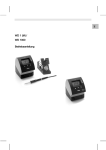
Geräteübersicht
1
2
3
4
5
6
7
8
9
10
11
12
13
14
15
16
17
18
19
20
21
22
23
24
25
26
27
LED Kanalauswahl
LED optische Regelkontrolle
LED Vakuum
Display
UP-Taste
DOWN-Taste
Kanalwahl/Temperaturtasten
┌ 1 ┐, ┌ 2 ┐, ┌ 3 ┐
Start/Stopp Pick-Up
Zustandsanzeige LED
Pick-Up
Temperaturtaste ┌ 1·2·3 ┐
Kanalwahl
Heißluft Einstelltaste (Air)
Netzschalter
Anschlüsse Pick-Up
Anschluss Vakuum (Vac)
Anschluss Heißluft (Air)
Anschlussbuchsen
Lötwerkzeug Kanal
┌ 1 ┐, ┌ 2 ┐, ┌ 3 ┐
Temperaturanzeige
Temperatursymbol
Zeitfunktionen
Verriegelung
Optische Regelkontrolle
Anzeige Kanalwahl
Anzeige Festtemperatur
Anzeige Sonderfunktionen
USB-Schnittstelle
Netzsicherung
Netzanschluss
28 Potentialausgleichsbuchse
3 Lieferumfang .............................................................................. 4
4 Gerätebeschreibung .................................................................. 5
5 Gerät in Betrieb nehmen ............................................................ 7
6 Gerät bedienen .......................................................................... 8
7 Sonderfunktionen....................................................................... 10
8 Zurücksetzen auf Werkseinstellungen ....................................... 19
EN
FR
2 Zu Ihrer Sicherheit ..................................................................... 4
IT
1 Zu dieser Anleitung .................................................................... 3
ES
Inhalt
DE
3-22
PT
WR 3M
Z Bewahren Sie diese Anleitung so auf, dass sie für alle Benutzer
zugänglich ist.
1.1
Berücksichtigte Richtlinien
Die Weller mikroprozessorgeregelte Reparaturstation WR 3M
entspricht den Angaben der EG Konformitätserklärung mit den
Richtlinien 2004/108/EG, 2006/95/EG und 2011/65/EU (RoHS).
1.2
Mitgeltende Dokumente
− Betriebsanleitung der Reparaturstation WR 3M
− Begleitheft Sicherheitshinweise zu dieser Anleitung
SV
DK
FI
GR
TR
CZ
PL
Z Lesen Sie diese Anleitung und die beiliegenden
Sicherheitshinweise vor Inbetriebnahme des Gerätes vollständig,
bevor Sie mit der Reparaturstation WR 3M arbeiten.
HU
Wir danken Ihnen für das mit dem Kauf der Weller WR 3M
erwiesene Vertrauen. Bei der Fertigung wurden strengste
Qualitätsanforderungen zugrunde gelegt, die eine einwandfreie
Funktion des Gerätes sicherstellen.
Diese Anleitung enthält wichtige Informationen, um die
Reparaturstation WR 3M sicher und sachgerecht in Betrieb zu
nehmen, zu bedienen, zu warten und einfache Störungen selbst zu
beseitigen.
SK
1 Zu dieser Anleitung
SL
13 Garantie ..................................................................................... 22
EE
12 Entsorgung ................................................................................ 22
LV
11 Zubehör ..................................................................................... 21
LT
10 Fehlermeldungen und Fehlerbehebung..................................... 20
NL
9 WR 3M pflegen und warten ....................................................... 19
4-22
WR 3M
2 Zu Ihrer Sicherheit
Die Reparaturstation WR 3M wurde entsprechend dem heutigen
Stand der Technik und den anerkannten sicherheitstechnischen
Regeln hergestellt. Trotzdem besteht die Gefahr von Personen- und
Sachschäden, wenn Sie die Sicherheitshinweise im beiliegenden
Sicherheitsheft sowie die Warnhinweise in dieser Anleitung nicht
beachten. Geben Sie die Reparaturstation WR 3M an Dritte stets
zusammen mit der Betriebsanleitung weiter.
2.1
Bestimmungsgemäßer Gebrauch
Verwenden Sie die Reparaturstation WR 3M ausschließlich gemäß
dem in der Bedienungsanleitung angegebenen Zweck zum Löten
und Entlöten unter den hier angegebenen Bedingungen. Der
bestimmungsgemäße Gebrauch der Reparaturstation WR 3M
schließt auch ein, dass
− Sie diese Anleitung beachten,
− Sie alle weiteren Begleitunterlagen beachten,
− Sie die nationalen Unfallverhütungsvorschriften am Einsatzort
beachten.
Für eigenmächtig vorgenommene Veränderungen am Gerät wird
vom Hersteller keine Haftung übernommen.
3 Lieferumfang
−
−
−
−
−
−
−
−
−
Reparaturstation WR 3M
Netzkabel
Luftschlauchadapter für Hot Air Pencil 1 (HAP 1)
Bedienungsanleitung WR 3M
Heft Sicherheitshinweise
CD mit USB-Software (“Firmware Updater” und “Monitorsoftware”)
USB-Kabel
Potentialausgleichsstecker
Packung mit farbigen Werkzeugmarkierungen
EN
FR
IT
ES
PT
NL
SV
DK
FI
GR
TR
CZ
PL
HU
SK
SL
Soll- und Ist-Wert werden digital angezeigt. Drei Temperaturtasten
dienen zur direkten Anwahl von Festtemperaturen. Das Erreichen
der vorgewählten Temperatur wird durch Blinken der optischen
Regelkontrolle („a“ Symbol im Display und zusätzlicher grüner LED)
signalisiert.
Die Weller WR 3M Reparaturstation bietet folgende weitere
Funktionen:
− Automatische Werkzeugerkennung und Aktivierung der
entsprechenden Regelparameter
− Alle Wellerwerkzeuge inkl. HAP 200 sind anschließbar
(ausgenommen WX-Werkzeuge)
− Digitale Temperaturregelung
− Eingabemöglichkeit von Offset-Werten
− Programmierbare Temperaturabsenkung (Setback)
− Standby- und Verriegelungsfunktion
− Eingebaute Hochleistungspumpe
− Antistatische Ausführung des Gerätes nach ESD-Sicherheit
− Verschiedene Potentialausgleichsmöglichkeiten am Gerät
(Standardkonfiguration)
− Kundenspezifische Kalibrierfunktion
− USB-Schnittstelle für Steuerung, Auswertung und Dokumentation
über PC
− Zusätzlicher Vakuumkanal für Bauteilehandling
EE
Die Weller WR 3M ist eine vielseitig verwendbare Reparaturstation
für professionelle Reparaturarbeiten an elektronischen Baugruppen
neuester Technologie in der industriellen Fertigungstechnik sowie im
Reparatur- und Laborbereich. Die WR 3M besitzt 3 unabhängige
Kanäle für den gleichzeitigen Betrieb von 3 Lötwerkzeugen.
Die digitale Regelelektrotechnik gewährleistet zusammen mit einer
hochwertigen Sensor- und Wärmeübertragungstechnik im
Lötwerkzeug ein präzises Temperaturregelverhalten an der
Lötspitze. Die schnelle Messwerterfassung sorgt für höchste
Temperaturgenauigkeit und ein optimales dynamisches
Temperaturverhalten im Belastungsfall. Die gewünschte Temperatur
kann in Abhängigkeit des angeschlossenen Werkzeugs im Bereich
von 50 °C bis 550 °C (150 °F – 999 °F) eingestellt werden. Soll- und
Ist-Wert werden digital angezeigt.
LV
4 Gerätebeschreibung
DE
5-22
LT
WR 3M
6-22
WR 3M
4.1
Technische Daten WR 3M
Abmessungen
L x B x H (mm): 273 x 235 x 102
L x B x H (inch): 10,75 x 9,25 x 4,02
Gewicht
ca. 6,7 kg
Netzspannung
230 V, 50 Hz (120 V, 60 Hz)
Leistungsaufnahme
400 W
Schutzklasse
I und III, Gehäuse antistatisch
Sicherung
Überstromauslöser
230 V 2,0 A
120 V 4,0 A
Temperaturregelung der
Kanäle
Löt- und Entlötkolben stufenlos
50 °C – 550 °C (150 °F – 999 °F)
Regelbarer Temperaturbereich ist
werkzeugabhängig.
WP 80 / WP 120
50 °C-450 °C (150 °F-850 °F)
WSP 150
50 °C-550 °C (150 °F-950 °F)
WP 200
50 °C-550 °C (150 °F-950 °F)
WMRT / WMRP
100 °C-450 °C (200 °F-850 °F)
DSX 80 / DXV 80
50 °C-450 °C (150 °F-850 °F)
DSX 120
50 °C-450 °C (150 °F-850 °F)
HAP 200 / HAP 1
50 °C-550 °C (150 °F-950 °F)
Temperaturgenauigkeit
± 9 °C (± 17 °F)
Temperaturstabilität
± 2 °C (± 4 °F)
Ableitwiderstand Lötspitze
(Tip to ground)
Entspricht IPC-J-001
Ableitspannung Lötspitze
(Tip to ground)
Entspricht IPC-J-001
Pumpe (Aussetzbetrieb
(30/30) s)
Max. Unterdruck 0,7 bar
Max. Fördermenge 18 l/min
Heißluft max. 15 l/min
Zusätzliche Vakuumpumpe Max. Unterdruck 0,5 bar
Max. Fördermenge 1,7 l/min
Potentialausgleich
Über 3,5 mm Schaltklinkenbuchse an
der Geräterückseite.
Z Schließen Sie den Vakuumschlauch nie am „Air“-Nippel
an!
1. Das Gerät sorgfältig auspacken.
2. Die Lötwerkzeuge wie folgt anschließen:
- Heißluftpencil (HAP) mit Luftschlauch am „Air“-Nippel (15)
anschließen und mit Anschlussstecker in die Anschlussbuchse
┌ 1 ┐, ┌ 2 ┐ oder ┌ 3 ┐ (16) der Reparaturstation einstecken und
durch kurze Rechtsdrehung verriegeln. Der HAP 1
Heißluftkolben ist nur mit Luftschlauchadapter anschließbar.
Hinweis
Wenn Sie einen HAP 200 einsetzen, kann dieser nur an Kanal 1
angeschlossen werden! Die maximale Ausgangsleistung ist auf
360 Watt begrenzt.
- Entlötwerkzeug mit Vakuumschlauch an „Vac“-Nippel (14)
anschließen und mit Anschlussstecker in die Anschlussbuchse
┌ 1 ┐, ┌ 2 ┐ oder ┌ 3 ┐ (16) der Reparaturstation einstecken und
durch kurze Rechtsdrehung verriegeln.
- Lötwerkzeug mit Anschlussstecker in die Anschlussbuchse
┌ 1 ┐, ┌ 2 ┐ oder ┌ 3 ┐ (16) der Reparaturstation einstecken und
durch kurze Rechtsdrehung verriegeln.
- Zwei Pick-Up- Werkzeuge (WRK, WVP) können mit dem
Vakuumschlauch an den beiden Pick-Up-Nippeln (13)
angeschlossen werden, wobei nur der rechte Nippel aktiv ist.
EN
FR
IT
ES
PT
NL
SV
DK
FI
GR
TR
Bei falsch angeschlossenem Vakuumschlauch kann bei
Betätigen des Entlötkolbens heiße Luft und flüssiges Lötzinn
austreten und zu Verletzungen führen.
CZ
Vakuumschlauch.
PL
WARNUNG! Verletzungsgefahr durch falsch angeschlossenen
HU
5 Gerät in Betrieb nehmen
SK
Durch unterschiedliche Beschaltung der 3,5 mm
Schaltklinkenbuchse (28) sind 4 Varianten möglich:
− Hart geerdet: Ohne Stecker (Auslieferungszustand).
− Mittelkontakt.
− Potentialfrei: Mit Stecker
− Weich geerdet: Mit Stecker und eingelötetem Widerstand. Erdung
über den gewählten Widerstand
SL
Potentialausgleich
EE
Das Steuergerät ist mit einer Mini USB-Schnittstelle (25)
ausgerüstet. Zur Nutzung der USB-Schnittstelle steht Ihnen eine
Weller-Software auf CD zur Verfügung mit der Sie
− ein Software Update („Firmware Updater“) an Ihrem Steuergerät
durchführen können und
− das Steuergerät fernbedienen sowie Temperaturkurven grafisch
darstellen, speichern und ausdrucken können („Monitorsoftware“).
LV
USB-Schnittstelle
DE
7-22
LT
WR 3M
8-22
WR 3M
3.
4.
5.
6.
Durch eine Drehung um 180 ° kann auf den anderen Nippel
umgeschaltet werden.
Die Lötwerkzeuge in der Sicherheitsablage ablegen.
Überprüfen, ob die Netzspannung mit der Angabe auf dem
Typenschild übereinstimmt und der Netzschalter (12) sich in
ausgeschaltetem Zustand befindet.
Das Steuergerät mit dem Netz verbinden (27).
Das Gerät am Netzschalter (12) einschalten.
Nach dem Einschalten des Gerätes führt der Mikroprozessor einen
Selbsttest durch, in dem alle Segmente kurzzeitig in Betrieb sind.
Danach schaltet die Elektronik automatisch in die TemperaturGrundeinstellung von 350 °C für alle Kanäle und 50 % für die „Air“Einstellung. Bei aktivierten Kanälen, die benutzt werden, leuchtet die
grüne LED (2) auf:
− Konstantes grünes Leuchten der LED signalisiert das Aufheizen
des angeschlossenen Werkzeugs.
− Grünes Blinken der LED signalisiert das Erreichen der
vorgewählten Werkzeugtemperatur.
Aktive Kanäle werden im Display mit Dreieck (22) sowie mit einem
Blitzsymbol (21) angezeigt.
6 Gerät bedienen
6.1
Kanal auswählen, ein- oder ausschalten
1. Eine der Tasten ┌ 1 ┐, ┌ 2 ┐ oder ┌ 3 ┐ drücken, um einen der
drei Kanäle auszuwählen.
Im Display erscheinen die Soll-Temperatur des angewählten
Kanals sowie in kleiner Schrift die fest programmierten
Temperaturen.
- Oder Taste ┌ 1·2·3 ┐antippen bis der gewünschte Kanal angezeigt
wird.
Im Display erscheint dann die aktuelle Werkzeugtemperatur. Im
unteren Bereich wird zusätzlich der Status mit entsprechender
Sollwerttemperatur angezeigt.
Der ausgewählte Kanal wird durch ein Dreieck (21) im Display
sowie durch eine rot leuchtende LED (1) am Gerät angezeigt.
2. Taste UP und DOWN gleichzeitig drücken, bis drei Striche „- - -“
im Display erscheinen.
3. Tasten los lassen.
Ist der Kanal nun deaktiviert, erscheint im Display die Anzeige
„OFF“.
Ist der Kanal aktiviert, erscheint im Display die aktuelle
Isttemperatur.
Gespeicherte Daten gehen durch das Ausschalten eines Kanals
nicht verloren.
Hinweis Die Anzeige wechselt automatisch zu dem Kanal, an dem ein
Werkzeug neu angeschlossen, der Fingerschalter gedrückt oder das
Werkzeug aus der Schaltablage genommen wurde. Diese Funktion
kann im Sonderfunktionen Menü 2 (siehe „Automatischer
Der Temperatursollwert kann für jeden Kanal getrennt durch die
Anwahl von drei voreingestellten Temperaturwerten
(Festtemperaturen) eingestellt werden.
Werkseitige Einstellungen:
┌ 1 ┐ = 150 °C (300 °F), ┌ 2 ┐ = 350 °C (662 °F),
┌ 3 ┐ = 380 °C (716 °F)
1. Kanal auswählen.
Anzeige von 3 Festtemperaturen im Display für ca. 2 s.
Solange das Temperatursymbol blinkt, kann die
Temperaturwerteingabe erfolgen.
2. Temperatursollwert mit Taste UP oder DOWN einstellen.
3. Gewünschte Temperaturtaste ┌ 1 ┐, ┌ 2 ┐ oder ┌ 3 ┐ drei
Sekunden lang gedrückt halten.
Währenddessen blinkt die Temperaturanzeige für den
entsprechenden Temperaturwert. Nach 3 Sekunden wird der
eingestellte Wert gespeichert.
4. Temperaturtaste wieder loslassen.
Die Belegung einer Temperaturtaste mit einer niedrigen „Setback“Temperatur bietet die Möglichkeit der manuellen
Temperaturabsenkung bei Nichtgebrauch des Lötkolbens.
1. Kanal auswählen.
2. Anzeige von 3 Festtemperaturen im Display für ca. 2 s.
Solange das Temperatursymbol blinkt, kann die gewünschte
Temperatur mit ┌ 1 ┐, ┌ 2 ┐ oder ┌ 3 ┐ angewählt werden.
EN
FR
IT
ES
PT
NL
SV
LV
Temperatur mit Temperaturtasten ┌ 1 ┐, ┌ 2 ┐ und ┌ 3 ┐ anwählen
LT
Hinweis
DK
Temperatur mit Temperaturtasten ┌ 1 ┐, ┌ 2 ┐ und ┌ 3 ┐ einstellen
FI
Ca. 2 Sekunden nach Loslassen der Einstelltasten erscheint im
Display wieder der Istwert des ausgewählten Kanals.
GR
Das Display schaltet auf den eingestellten Sollwert um. Das
Temperatursymbol (18) blinkt.
3. Die Taste UP oder DOWN drücken, um die gewünschte
Solltemperatur einzustellen:
- Kurzes Tippen verstellt den Sollwert um ein Grad.
- Permanentes Drücken verstellt den Sollwert im
Schnelldurchlauf.
TR
Das Display zeigt den Temperatur-Istwert des ausgewählten
Kanals an.
2. Die Taste UP oder DOWN drücken.
CZ
1. Den gewünschten Kanal durch Drücken einer der Tasten ┌ 1 ┐,
┌ 2 ┐ oder ┌ 3 ┐ auswählen.
PL
Temperatur individuell einstellen
HU
Temperatur einstellen
SK
6.2
SL
Kanalwechsel deaktivieren / aktivieren“ Seite 18) deaktiviert werden.
DE
9-22
EE
WR 3M
10-22
WR 3M
6.3 Luftdurchfluss einstellen
Der Luftdurchfluss kann, ausgehend von einem maximalen
Durchflusswert von 15 l/s (HAP 200) bzw. 10 l/s (HAP 1), in einem
Bereich von 10 % bis 100 % eingestellt werden.
1. Taste AIR drücken.
Der aktuelle Luftdurchfluss in Prozent wird für ca. 2 s im Display
angezeigt.
2. Gewünschten Durchfluss durch Drücken der Taste UP- oder
DOWN einstellen.
Der eingestellte Wert wird übernommen. Nach 3 s wird wieder
die Ist-Temperatur des gewählten Kanals angezeigt
Hinweis
Wie bei den 3 Festtemperaturen können auch 3 Festluftmengen
eingestellt und angewählt werden.
Werkseitige Einstellungen:
┌ 1 ┐ = 10 %, ┌ 2 ┐ = 50 %, ┌ 3 ┐ = 100 %
6.4
Vakuum Pick-Up-Pumpe ein-/ausschalten
Z Pick-Up-Taste drücken.
Je nach Ausgangszustand wird die Pumpe ein- oder
ausgeschaltet. Im eingeschalteten Modus leuchtet die der Taste
Pick-Up benachbarte LED (8) grün.
Hinweis
Die Vakuumpumpe ist nicht auf Dauerbetrieb ausgelegt. Zum
Schutz der Pumpe schaltet sich diese nach 10 Minuten
Dauerbetrieb automatisch aus.
6.5
Löten und Entlöten
Z Führen Sie die Lötarbeiten gemäß der Bedienungsanleitung Ihres
angeschlossenen Lötwerkzeuges durch.
7 Sonderfunktionen
2s➾
Menü 1
4s➾
Menü 2
1x ➾
ON/OFF
Die Sonderfunktionen sind in 2 Menüebenen eingeteilt:
− Menü 1 mit Einstellungsmöglichkeiten für
Standby-Temperatur, Temperaturabschaltung (Setback),
Automatische Abschaltzeit (Auto-OFF), Temperatur-Offset,
Window-Funktion, Temperatureinheiten, Einschaltzeit (On Time)
für Heißluftpencil, Vakuum Abschaltverzögerung (VAC OFF) und
Vakuum Einschaltverzögerung (VAC ON) und
Verriegelungsfunktion.
− Menü 2 mit Einstellungsmöglichkeiten für
Manometerlevel, ID Code, Kalibrierungsfunktion (FCC), Pick-UpLeistung, autom. Kanalwechsel ON / OFF, Tastenverriegelung
ON / OFF und Regelcharakteristik HI / LO.
11-22
Sonderfunktionen Menü 1 auswählen
Sonderfunktionen
Navigation
EN
7.1
DE
WR 3M
STANDBY
°C/°F
ON TIME
VAC OFF
┌1┐
↑
┌2┐
EXIT
┌3┐
IT
WINDOW
↓
ES
OFFSET
Standby-Temperatur einstellen
Nach einer Temperaturabschaltung wird automatisch die StandbyTemperatur eingestellt. Die Isttemperatur wird blinkend angezeigt.
Im Display erscheint „STANDBY“.
1. Menüpunkt STANDBY im Menü 1 auswählen.
2. Sollwert für Standby-Temperatur mit Taste UP oder DOWN
einstellen.
3. Mit Taste ┌ 1 ┐ (zurück) oder ┌ 2 ┐ (vor) zum nächsten
Menüpunkt wechseln.
DK
FI
GR
TR
CZ
PL
HU
Im Display erscheint „FSE“.
Die Reparaturstation ist nun wieder auf die Werkseinstellungen
zurückgesetzt.
SK
1. Taste ┌ 3 ┐ drücken und gedrückt halten.
2. Anschließend die Tasten UP und DOWN gleichzeitig drücken.
SL
Zurücksetzen der Sonderfunktionen auf die Werkseinstellungen
EE
Die Auswahl der Sonderfunktionen des Menüs 1 ist aktiviert.
Die Einstellungen können nun vorgenommen werden.
- Mit Tasten ┌ 1 ┐, ┌ 2 ┐ Menüpunkte auswählen.
- Mit Taste ┌ 3 ┐ Menü wieder verlassen (EXIT).
LV
Nach 2 s erscheint im Display die Anzeige „– 1 –“.
3. Tasten loslassen.
LT
1. Gewünschten Kanal ┌ 1 ┐, ┌ 2 ┐ oder ┌ 3 ┐ für die Eingabe der
Sonderfunktionen auswählen.
2. Taste UP und DOWN gleichzeitig gedrückt halten.
SV
NL
VAC ON
PT
AUTO OFF
FR
SETBACK
12-22
WR 3M
Temperaturabschaltung (SETBACK) einstellen
Bei Nichtgebrauch des Lötwerkzeugs wird die Temperatur nach
Ablauf der eingestellten Setback-Zeit auf Standby-Temperatur
abgesenkt. Der Setbackzustand wird durch eine blinkende
Istwertanzeige angezeigt und im Display wird „STANDBY“
angezeigt. Drücken der Taste UP oder DOWN beendet diesen
Setbackzustand. Werkzeugabhängig deaktiviert der Fingerschalter
oder die Schaltablage den Setback-Zustand.
Folgende Setback-Einstellungen sind möglich:
− „0 min“: Setback OFF (Werkseinstellung)
− „ON“: Setback ON (mit Schaltablage wird nach dem Ablegen des
Lötkolbens sofort auf Standby-Temperatur heruntergeregelt).
− „1-99 min“: Setback ON (individuell einstellbare Setback-Zeit)
1. Menüpunkt SETBACK im Menü 1 auswählen.
2. Setback-Wert mit Taste UP oder DOWN einstellen.
3. Mit Taste ┌ 1 ┐ (zurück) oder ┌ 2 ┐ (vor) zum nächsten
Menüpunkt wechseln.
Automatische Abschaltzeit (AUTO-OFF) einstellen
Bei Nichtgebrauch des Lötwerkzeugs wird nach Ablauf der
AUTO-OFF-Zeit die Heizung des Lötwerkzeuges abgeschaltet.
Die Temperaturabschaltung wird unabhängig von der eingestellten
Setback-Funktion ausgeführt. Die Isttemperatur wird blinkend
angezeigt und dient als Restwärmeanzeige. Im Display erscheint
„OFF“. Unterhalb von 50 °C (122 °F) erscheint ein blinkender Strich
im Display.
Folgende AUTO-OFF-Zeit-Einstellungen sind möglich:
− „0 min“: AUTO-OFF-Funktion ist ausgeschaltet.
− „1-999 min“: AUTO-OFF-Zeit, individuell einstellbar.
1. Menüpunkt OFF im Menü 1 auswählen.
2. AUTO-OFF-Zeitsollwert mit Taste UP oder DOWN einstellen.
3. Mit Taste ┌ 1 ┐ (zurück) oder ┌ 2 ┐ (vor) zum nächsten
Menüpunkt wechseln.
Einstellungen
Temperaturverhalten ohne Schaltablage
SETBACK
OFF Time
Time [1-99 min] [1-999 min]
Lötwerkzeug wird in der Ablage3) auf die STANDBY-Temperatur2)
heruntergeregelt.
0
Time
Lötwerkzeug wird in der Ablage3) nach Ablauf der OFF-Zeit
abgeschaltet.
ON
Time
Lötwerkzeug wird in der Ablage3) auf die STANDBY-Temperatur2)
heruntergeregelt und nach Ablauf der OFF-Zeit abgeschaltet.
Time
0
Lötwerkzeug wird in der Ablage3) nach der SETBACK-Zeit auf die
STANDBY-Temperatur2) heruntergeregelt.
Time
Time
Lötwerkzeug wird in der Ablage3) nach Ablauf der SETBACK-Zeit
auf die STANDBY-Temperatur2) heruntergeregelt und nach Ablauf
der OFF-Zeit abgeschaltet.
1)
Nichtgebrauch = kein Drücken der UP/DOWN-Tasten und kein Temperaturabfall > 5 °C.
2)
STANDBY-Temperatur muss unter der eingestellten Solltemperatur liegen, sonst ist die SETBACKFunktion inaktiv.
3)
Wenn eine Schaltablage angeschlossen ist, bleibt das Lötwerkzeug außerhalb der Ablage immer
auf der eingestellten Solltemperatur.
Die Ablagefunktion wird nach dem ersten Ablegen des Lötwerkzeugs aktiviert
Hinweis
Reset von STANDBY- und OFF-Modus:
− Ohne Schaltablage durch Drücken der UP- oder DOWN-Taste.
− Mit Schaltablage durch Entnehmen des Lötwerkzeugs aus der
Ablage.
NL
PT
ES
IT
0
SV
ON
DK
Lötwerkzeug wird in der Ablage3) abgeschaltet.
FI
0
GR
0
TR
Temperaturverhalten mit Schaltablage
CZ
Time
Lötwerkzeug wird bei Nichtgebrauch1) nach Ablauf der SETBACKZeit auf die STANDBY-Temperatur2) heruntergeregelt und nach
Ablauf der OFF-Zeit abgeschaltet.
PL
Lötwerkzeug wird bei Nichtgebrauch1) nach Ablauf der SETBACKZeit auf die STANDBY-Temperatur2) heruntergeregelt.
HU
Time
0
SK
Time
Lötwerkzeug wird bei Nichtgebrauch1) nach Ablauf der OFF-Zeit
abgeschaltet.
SL
ON
Time
EE
0
Lötwerkzeug bleibt auf der eingestellten Löttemperatur.
0
LV
ON
LT
0
EN
Temperaturverhalten bei unterschiedlichen Einstellungen der
SETBACK- und AUTO OFF-Funktionen
DE
13-22
FR
WR 3M
14-22
WR 3M
Temperatur-Offset einstellen
Die reale Lötspitzentemperatur kann durch Eingabe eines
Temperatur-offsets um ± 40 °C (± 72 °F) angepasst werden.
1. Menüpunkt OFFSET im Menü 1 auswählen.
2. OFFSET-Temperaturwert mit Taste UP oder DOWN einstellen.
3. Mit Taste ┌ 1 ┐ (zurück) oder ┌ 2 ┐ (vor) zum nächsten
Menüpunkt wechseln.
Window-Funktion einstellen
Ausgehend von einer eingestellten, verriegelten Temperatur, kann
mit Hilfe der WINDOW-Funktion ein Temperaturfenster von ± 99 °C
(± 180 °F) eingestellt werden.
Hinweis
Um die WINDOW-Funktion nutzen zu können, muss die
Reparaturstation im verriegelten Zustand (siehe
„Verriegelungsfunktion ein-/ausschalten“ Seite 15) sein.
1. Menüpunkt WINDOW im Menü 1 auswählen.
2. WINDOW-Temperaturwert mit Taste UP oder DOWN einstellen.
3. Mit Taste ┌ 1 ┐ (zurück) oder ┌ 2 ┐ (vor) zum nächsten
Menüpunkt wechseln.
Temperatureinheit umstellen
Umschalten der Temperatureinheit von °C in °F oder umgekehrt.
1. Menüpunkt °C / °F im Menü 1 auswählen.
2. Temperatureinheit mit Taste UP oder DOWN einstellen.
3. Mit Taste ┌ 1 ┐ (zurück) oder ┌ 2 ┐ (vor) zum nächsten
Menüpunkt wechseln.
Einschaltzeit (ON TIME) für Heißluftkolben (HAP) begrenzen
Die Einschaltzeit für den Heißluftstrom des HAP kann in 1erSchritten von 0 bis 60 s begrenzt werden. Die eingestellte Zeit ist
dann für alle 3 Kanäle gleich. Werkseinstellung ist 0 s („OFF“), d. h.
der Luftstrom wird aktiviert, solange der Taster am Heißluftkolben
oder der optionale Fußschalter gedrückt ist.
1. Menüpunkt HAP-TIME im Menü 1 auswählen.
2. Zeitwert mit Taste UP oder DOWN einstellen.
3. Mit Taste ┌ 1 ┐ (zurück) oder ┌ 2 ┐ (vor) zum nächsten
Menüpunkt wechseln.
Vakuum Abschaltverzögerung (VAC Off) einstellen
Um das Verstopfen des Entlötkolbens zu verhindern, kann eine
Vakuum Off-Zeitverzögerung von 0 bis 5 s eingestellt werden
(Werkseinstellung 2 s).
1. Menüpunkt VAC OFF im Menü 1 auswählen.
2. Zeitwert (VAC OFF) mit Taste UP oder DOWN einstellen.
3. Mit Taste ┌ 1 ┐ (zurück) oder ┌ 2 ┐ (vor) zum nächsten
Menüpunkt wechseln.
Reparaturstation entriegeln:
1. Menüpunkt LOCK im Menü 1 auswählen.
Im Display wird „ON“ angezeigt. Das Schlüsselsymbol wird
angezeigt.
2. 3-stelligen Verriegelungscode mit Taste UP oder DOWN
eingeben.
3. Taste ┌ 3 ┐ drücken.
Die Station ist nun entriegelt. Die Anzeige wechselt in das
Hauptmenü.
EN
FR
IT
ES
PT
NL
SV
DK
FI
GR
TR
2. 3-stelligen Verriegelungscode mit Taste UP oder DOWN
einstellen.
3. Taste ┌ 3 ┐ 5 s lang drücken.
Der Code wird gespeichert. Das Schlüsselsymbol wird angezeigt.
Die Station ist nun verriegelt. Die Anzeige wechselt in das
Hauptmenü.
CZ
Drücken der Tasten ┌ 1 ┐ oder ┌ 2 ┐ während „OFF“ angezeigt
wird, führt zum Verlassen des Menüpunktes ohne abgespeicherten
Verriegelungscode.
PL
Hinweis
HU
Reparaturstation verriegeln:
1. Menüpunkt LOCK im Menü 1 auswählen.
Im Display wird „OFF“ angezeigt. Das Schlüsselsymbol blinkt.
SK
Nach Einschalten der Verriegelung sind an der Reparaturstation nur
noch die Temperaturtasten ┌ 1 ┐, ┌ 2 ┐ und ┌ 3 ┐, Pick-Up und
┌ 1·2·3 ┐ bedienbar. Alle anderen Einstellungen können bis zur
Entriegelung nicht mehr verstellt werden.
SL
Verriegelungsfunktion ein-/ausschalten
EE
Um ein vorzeitiges Starten der Pumpe zu verhindern oder um eine
definierte Vorwärmzeit der Lötstelle zu gewährleisten, kann eine
Einschaltverzögerung von 0 bis 9 s eingestellt werden
(Werkseinstellung 0 s: Off).
1. Menüpunkt VAC ON im Menü 1 auswählen.
2. Zeitwert (VAC ON) mit Taste UP oder DOWN einstellen.
3. Mit Taste ┌ 1 ┐ (zurück) oder ┌ 2 ┐ (vor) zum nächsten
Menüpunkt wechseln.
LV
Vakuum Einschaltverzögerung (VAC ON) einstellen
DE
15-22
LT
WR 3M
16-22
WR 3M
7.2
Sonderfunktionen Menü 2 auswählen
Sonderfunktionen
Navigation
LEVEL
ID
FCC
PICK-UP
HAP LOCK
↓
↑
EXIT
┌1┐
┌2┐
┌3┐
HI / LO CONTROL
AUTO CHANNEL
1. Gewünschten Kanal ┌ 1 ┐, ┌ 2 ┐ oder ┌ 3 ┐ für die Eingabe der
Sonderfunktionen auswählen.
2. Tasten UP- und DOWN gleichzeitig gedrückt halten.
Nach 4 s erscheint im Display die Anzeige „– 2 –“.
3. Tasten loslassen.
Die Auswahl der Sonderfunktionen des Menüs 2 ist aktiviert.
Die Einstellungen können nun vorgenommen werden.
Mit Tasten ┌ 1 ┐ und ┌ 2 ┐ Menüpunkte auswählen.
Mit Taste ┌ 3 ┐ Menü wieder verlassen (EXIT).
Manometerschwelle festlegen
− Mit dieser Funktion kann das Wartungsintervall des
Entlötwerkzeugs definiert werden. Hierbei wird der Wert in mbar
festgelegt, bei dem das elektrische Manometer bei verschmutztem
Saugsystem eine Warnmeldung auslöst (LED (3) der
Vakuumpumpe wechselt von grün auf rot). Der eingestellte Wert
hängt von den verwendeten Saugdüsen ab.
− Werkseinstellung: -600 mbar
Einstellbar: -400 mbar bis -800 mbar
1. System (Spitzen und Filter) müssen frei sein
2. Menüpunkt LEVEL im Menü 2 auswählen.
3. LEVEL -Druckwert mit Taste UP oder DOWN einstellen.
Die LED Regelkontrolle schaltet von rot auf grün hin und her. Mit
Taste UP den Unterdruck um 50 bis 80 mbar erhöhen, den
Vakuumschlauch zusammendrücken und kontrollieren ob die
Kontrollleuchte von grün auf rot schaltet.
4. Mit Taste ┌ 1 ┐ (zurück) oder ┌ 2 ┐ (vor) zum nächsten
Menüpunkt wechseln.
Stationskennung (ID Code) einstellen
Bei Verwendung der optionalen USB-Schnittstelle können mehrere
WR 3M Reparaturstationen in vollem Funktionsumfang angesteuert
und fernbedient werden. Jede Station benötigt hierfür eine
Stationskennung (ID Code), um eindeutig identifiziert werden zu
können.
1. Menüpunkt REMOTE ID im Menü 2 auswählen.
2. Mit Taste UP oder DOWN eine ID eingeben
(Mögliche Werte 0 – 999).
3. Mit Taste ┌ 1 ┐ (zurück) oder ┌ 2 ┐ (vor) zum nächsten
Menüpunkt wechseln.
Hinweis
Taste ┌ 3 ┐ drücken, um den Menüpunkt ohne Veränderungen zu
verlassen (EXIT).
EN
FR
IT
ES
PT
NL
SV
Taste ┌ 3 ┐ drücken, um den Menüpunkt ohne Veränderungen zu
verlassen (EXIT).
EE
SL
SK
HU
PL
CZ
Kalibrierung bei 450 °C / 842 °F ändern
1. Temperaturfühler (0,5 mm) des externen Temperaturmessgeräts
in die Temperaturmessspitze einführen.
2. Menüpunkt FCC im Menü 2 auswählen.
3. Taste UP drücken.
Kalibrierpunkt 450 °C / 842 °F wird ausgewählt.
Die Lötspitze wird nun auf 450 °C / 842 °F aufgeheizt.
Die Regelkontrolle blinkt, sobald die Temperatur konstant ist.
4. Angezeigte Temperaturen des Messgerätes mit der Anzeige im
Display vergleichen.
5. Mit Taste UP oder DOWN die Differenz zwischen dem am
externen Messgerät angezeigten Wert und dem an der Station
angezeigten Wert an der Reparaturstation einstellen.
Maximal möglicher Temperaturabgleich ± 40 °C (± 72 °F).
Beispiel:
Display 450 °C, externes Messgerät 448 °C: Einstellung S 2
Display 450 °C, externes Messgerät 452 °C: Einstellung T 2
LV
Hinweis
Taste ┌ 3 ┐ drücken, um den Menüpunkt ohne Veränderungen zu
verlassen (EXIT).
6. Drücken der Taste ┌ 2 ┐ (Set), um den Wert zu bestätigen.
Die Temperaturabweichung ist nun auf 0 zurückgesetzt. Die
Kalibrierung bei 100 °C / 212 °F ist nun abgeschlossen.
7. Mit Taste ┌ 3 ┐ das Menü 2 verlassen.
LT
Hinweis
DK
Kalibrierung bei 100 °C / 212 °F ändern
1. Temperaturfühler (0,5 mm) des externen Temperaturmessgeräts
in die Temperaturmessspitze einführen.
2. Menüpunkt FCC im Menü 2 auswählen.
3. Taste DOWN drücken.
Kalibrierpunkt 100 °C / 212 °F wird ausgewählt.
Die Lötspitze wird nun auf 100 °C / 212 °F aufgeheizt.
Regelkontrolle blinkt, sobald die Temperatur konstant ist.
4. Angezeigte Temperaturen des Messgerätes mit der Anzeige im
Display vergleichen.
5. Mit Taste UP oder DOWN die Differenz zwischen dem am
externen Messgerät angezeigten Wert und dem an der Station
angezeigten Wert an der Reparaturstation einstellen.
Maximal möglicher Temperaturabgleich ± 40 °C (± 72 °F).
Beispiel:
Display 100 °C, externes Messgerät 98 °C: Einstellung S 2
Display 100 °C, externes Messgerät 102 °C: Einstellung T 2
FI
Mit der FCC-Funktion können Sie die Temperaturgenauigkeit der
Reparaturstation überprüfen und eventuelle Abweichungen
ausgleichen. Hierfür muss die Lötspitzentemperatur mit einem
externen Temperaturmessgerät und einer dem Lötwerkzeug
zugeordneten Temperaturmessspitze gemessen werden. Vor der
Kalibrierung muss der entsprechende Kanal angewählt werden.
GR
Kalibrierfunktion (Factory Calibration Check) bedienen
DE
17-22
TR
WR 3M
18-22
WR 3M
6. Drücken der Taste ┌ 2 ┐ (Set), um den Wert zu bestätigen.
Die Temperaturabweichung ist nun auf 0 zurückgesetzt. Die
Kalibrierung bei 450 °C /842 °F ist nun abgeschlossen.
7. Mit Taste ┌ 3 ┐ das Menü 2 verlassen.
Kalibrierung auf Werkseinstellungen zurücksetzen
1. Menüpunkt FCC im Menü 2 auswählen.
2. Taste ┌ 3 ┐ gedrückt halten.
3. Anschließend Tasten UP und DOWN gleichzeitig drücken.
Im Display erscheint „FSE“ (Factory Setting Enabled).
Die Reparaturstation ist nun wieder auf die Werkskalibrierung
zurückgesetzt.
4. Mit Taste ┌ 1 ┐ (zurück) oder ┌ 2 ┐ (vor) zum nächsten
Menüpunkt wechseln.
Pick-Up-Leistung einstellen
Mit dieser Funktion kann die Leistung der zusätzlichen
Vakuumpumpe für den Pick-Up-Betrieb eingestellt werden:
− Werkseinstellung: 85 %
− Einstellbar: 50 % – 100 %
1. Menüpunkt LEVEL im Menü 2 auswählen.
2. LEVEL -Druckwert mit Taste UP oder DOWN einstellen.
3. Mit Taste ┌ 1 ┐ (zurück) oder ┌ 2 ┐ (vor) zum nächsten
Menüpunkt wechseln.
Automatischer Kanalwechsel deaktivieren / aktivieren
Mit dieser Funktion kann der werkseitig aktivierte automatische
Kanalwechsel deaktiviert werden:
1. Menüpunkt AUTO CHANNEL im Menü 2 auswählen.
2. Status mit Taste UP oder DOWN einstellen.
(ON = aktivieren / OFF = deaktivieren)
3. Mit Taste ┌ 1 ┐ (zurück) oder ┌ 2 ┐ (vor) zum nächsten
Menüpunkt wechseln.
Tastenverriegelung HAP aktivieren / deaktivieren
Hinweis
Mit dieser Funktion kann das werkseitig eingestellte Tastenverhalten
des HAP Kolbens verändert werden. Wird die Verriegelung aktiviert,
wird der HAP mit dem ersten Tastendruck ein- und mit einem
weiteren Tastendruck ausgeschaltet.
1. Menüpunkt HAP LOCK im Menü 2 auswählen.
2. Status mit Taste UP oder DOWN einstellen.
(ON = aktivieren / OFF = deaktivieren)
3. Mit Taste ┌ 1 ┐ (zurück) oder ┌ 2 ┐ (vor) zum nächsten
Menüpunkt wechseln.
Zum Schutz der Pumpe schaltet sich diese nach 20 Minuten
Dauerbetrieb automatisch aus.
Einstellen der Regelcharakteristik für WP 120
Mit der HI / LO CONTROL- Funktion kann die werkseitig auf HI
eingestellte Regelcharakteristik für WP 120 eingestellt werden:
1 Menüpunkt HI / LO im Menü 2 auswählen.
2. Status mit Taste UP (HI) oder DOWN (LO) einstellen.
Zurücksetzen der Sonderfunktionen
Diese Funktion wird unter „7.1 Sonderfunktionen Menü 1
auswählen“, „Zurücksetzen der Sonderfunktionen auf die
Werkseinstellungen“ auf Seite 11 beschrieben.
EN
8 Zurücksetzen auf Werkseinstellungen
DE
19-22
FR
WR 3M
WARNUNG! Zerstörung der Vakuumpumpe durch Arbeiten ohne
Filter.
ES
PT
GR
Z Kontrollieren Sie bevor Sie mit Lötarbeiten beginnen, ob ein
Hauptfilter eingelegt ist!
NL
Filter warten
Hauptfilter für “VACUUM” und “AIR” regelmäßig auf Verschmutzung
kontrollieren und gegebenenfalls erneuern.
SV
9.1
DK
9 WR 3M pflegen und warten
FI
Diese Funktion wird unter „7.2 Sonderfunktionen Menü 2
auswählen“, „Kalibrierung auf Werkseinstellungen zurücksetzen“ auf
Seite 16 beschrieben.
IT
Kalibrierung auf Werkseinstellungen zurücksetzen
CZ
PL
HU
SK
SL
EE
LV
Hierbei auf richtigen Sitz der Dichtung achten.
4. Druckfeder einsetzen.
5. Abdeckkappe unter leichtem Druck wieder aufsetzen und um
45° nach rechts drehen.
LT
1. Abdeckkappe „Vac“ (14) oder „Air“ (15) um 45° nach links drehen
und abnehmen.
2. Verschmutzten Filter herausziehen und ordnungsgemäß
entsorgen.
3. Eine original WELLER-Filterkartusche einsetzen.
TR
Filter austauschen
20-22
WR 3M
10 Fehlermeldungen und Fehlerbehebung
Meldung/Symptom
Mögliche Ursache
Maßnahmen zur Abhilfe
Anzeige „- - -“
− Werkzeug wurde nicht
erkannt
− Werkzeug defekt
− Anschluss des Werkzeugs am
Gerät überprüfen
− Angeschlossenes Werkzeug
überprüfen
HAP 200 funktioniert nicht
HAP 200 nicht am Kanal 1
angeschlossen
HAP 200 an Kanal 1 anschließen
Anzeige "tip"
Lötspitze des Microtools nicht
richtig eingesteckt oder defekt
− Lötspitze erneut einstecken
− Defekte Lötspitze tauschen
Pick-Up hält nicht
− Vakuum ist nicht vollständig
aufgebaut
− Schlauch defekt oder
abgeknickt
− Federvorspannung zu stark
− Vakuum am Pick-Up-Anschluss
überprüfen
− Schlauch tauschen
− Federvorspannung verringern
Keine Luft am HAP
Luftschlauch nicht oder falsch
angeschlossen
Luftschlauch am AIR-Nippel
anschließen
Kein Vakuum am
Entlötwerkzeug
− Vakuumschlauch nicht oder
falsch angeschlossen
− Entlötdüse verstopft
− Vakuumschlauch am Vac-Nippel
anschließen
− Entlötdüse mit
Reinigungswerkzeug warten
Statusanzeige der VAC LED's Manometer Level nicht richtig
stimmt nicht
eingestellt
Manometerlevel im
Sondermenü 2 einstellen
Keine Displayfunktion (Display keine Netzspannung vorhanden − Netzschalter einschalten
aus)
− Netzspannung überprüfen
− Gerätesicherung überprüfen
VAC LED rot
Vakuumsystem verstopft
− Saugdüse reinigen
− Filter (13) überprüfen; wenn
gelb, dann wechseln
− Entlötwerkzeug reinigen – Filter
ersetzen
− Vakuumschlauch prüfen
Weiteres Zubehör entnehmen Sie bitte den Betriebsanleitungen der
einzelnen Lötkolbensets.
EN
FR
IT
ES
PT
NL
SV
DK
FI
GR
TR
CZ
PL
HU
SK
LT
LV
T005 29 216 99 WP 65 Lötkolbenset mit Ablage WDH 10, 65 W
T005 29 181 99 WP 80 Lötkolbenset, 80 W
T005 29 161 99 WSP 80 Lötkolbenset, 80 W
T005 29 194 99 WP 120 Lötkolbenset mit Ablage WDH 10T, 120 W
T005 29 200 99 WP 200 Lötkolbenset mit Ablage WDH 31, 200 W
T005 29 189 99 WSP 150 Lötkolbenset, 150 W
T005 29 190 99 WMRP Micro-Lötkolbenset, 40 W
T005 13 173 99 WMRT Micro-Entlötpinzettenset, 80 W
T005 29 163 99 MPR 80 Lötkolben, 80 W
T005 33 155 99 WMP Lötkolbenset, 65 W
T005 29 187 99 LR 21 Lötkolbenset, 50 W
T005 29 188 99 LR 82 Lötkolbenset, 80 W
T005 33 133 99 WTA 50 Entlötpinzettenset, 50 W
T005 25 032 99 WST 82 KIT1 Thermisches Abisoliergeräteset, 80 W
T005 25 031 99 WST 82 KIT2Thermisches Abisoliergeräteset, 80 W
T005 27 040 99 WSB 80 Lötbad, 80 W
T005 27 042 99 WSB 150 Lötbad, 150 W
T005 27 028 99 WHP 80 Vorheizplatte, 80 W
T005 13 182 99 DXV 80 Entlötkolbenset, 80 W
T005 13 183 99 DSX 80 Entlötkolbenset, 80 W
T005 13 198 99 DSX 120 Entlötkolben, 120 W
T005 27 118 99 HAP 1 Heißluftkolbenset, 100 W
T005 15 154 99 WRK Ablagenset
T005 15 155 99 WRK Entlötset
T005 29 184 99 WVP Vakuumpipette
T005 27 116 99 HAP 200 Heißluftkolben
T005 27 117 99 HAP 200 Heißluftset
T005 15 152 99 WDH 30 Ablage für HAP 200/DSX 80/DSX 120
T005 15 153 99 WDH 40 Ablage für DXV 80
T005 15 158 99 WDH 31 Ablage für WP 200
T005 15 161 99 WDH 10T Schaltablage WSP 80/WP 80
T005 15 162 99 WDH 20T Schaltablage für WMP
T005 87 617 30 Entlötset 33x33/24x24 mit Pick-Up
T005 87 617 31 Entlötset 27x27/20x20 mit Pick-Up
T005 87 617 32 Entlötset 18/15,5/12,5/10 mit Pick-Up
T005 13 120 99 Fußschalter
T005 87 388 50 Adapter für Fußschalter
T005 15 125 99 WDC 2 Trockenreinigungseinsatz
T005 13 840 99 Spiralwolle für WDC
T005 87 597 28 Reset-Stecker °C
T005 87 597 27 Reset-Stecker °F
T005 87 658 01 PDN Entlötdüsenzange
SL
11 Zubehör
DE
21-22
EE
WR 3M
22-22
WR 3M
12 Entsorgung
Entsorgen Sie ausgetauschte Geräteteile, Filter oder alte Geräte
gemäß den Vorschriften Ihres Landes.
13 Garantie
Die Mängelansprüche des Käufers verjähren in einem Jahr ab
Ablieferung an ihn. Dies gilt nicht für Rückgriffsansprüche des
Käufers nach §§ 478, 479 BGB.
Aus einer von uns abgegebenen Garantie haften wir nur, wenn die
Beschaffenheits- oder Haltbarkeitsgarantie von uns schriftlich und
unter Verwendung des Begriffs „Garantie“ abgegeben worden ist.
Technische Änderungen vorbehalten!
Die aktualisierten Betriebsanleitungen finden Sie unter
www.weller-tools.com.
LV
EE
SL
SK
HU
PL
CZ
TR
GR
FI
DK
SV
NL
PT
ES
IT
Operating Instructions
LT
FR
WR 3M
EN
DE
WR 3M
WR 3M
Equipment overview
1
2
3
4
5
6
7
8
9
10
11
12
13
14
15
16
17
18
19
20
21
22
23
24
25
26
27
LED channel selection
LED optical control indicator
LED vacuum
Display
UP button
DOWN button
Channel selection /
temperature buttons
┌ 1 ┐, ┌ 2 ┐, ┌ 3 ┐
Start/stop pick-up
Status display LED pick-up
Temperature button ┌ 1·2·3 ┐
channel selection
Hot-air setting button (Air)
Mains power switch
Connections, pick-up
Connection, vacuum (Vac)
Connection, hot air (Air)
Connector sockets, soldering
tool channel
┌ 1 ┐, ┌ 2 ┐, ┌ 3 ┐
Temperature display
Temperature symbol
Time functions
Lock
Optical control check
Display, channel selection
Display, fixed temperature
Display, special functions
USB port
Mains system fuse
Mains system connection
28 Equipotential-bonding socket
3 Scope of delivery ....................................................................... 4
4 Device description ..................................................................... 5
5 Starting up the device ................................................................ 7
6 Operating the device.................................................................. 8
7 Special functions........................................................................ 10
8 Resetting to factory settings ...................................................... 19
EN
FR
2 For your safety ........................................................................... 4
IT
1 About these instructions ............................................................ 3
ES
Contents
DE
3-22
PT
WR 3M
Z Ensure that these instructions are accessible to all users.
1.1
Directives taken into consideration
The Weller microprocessor-controlled repair station WR 3M
complies with the specifications of the EC Declaration of Conformity
based on Directives 2004/108/EC, 2006/95/EC and 2011/65/CE
(RoHS).
1.2
Documents also applicable
− Operating Instructions for the repair station WR 3M
− Safety information booklet accompanying these instructions
SV
DK
FI
GR
TR
CZ
PL
Z Read these instructions and the accompanying safety information
carefully before starting up the device and starting work with the
WR 3M repair station.
HU
Thank you for the confidence you have shown in buying the
Weller WR 3M. Production was based on stringent quality
requirements which guarantee the perfect operation of the device.
These instructions contain important information which will help you
to start up, operate and service the WR 3M repair station safely and
correctly as well as to eliminate simple faults/malfunctions
yourselves.
SK
1 About these instructions
SL
13 Warranty .................................................................................... 22
EE
12 Disposal ..................................................................................... 22
LV
11 Accessories ............................................................................... 21
LT
10 Fault messages and fault elimination ........................................ 20
NL
9 Care and maintenance of the WR 3M ....................................... 19
4-22
WR 3M
2 For your safety
The WR 3M repair station has been manufactured in accordance
with state-of-the-art technology and recognised safety rules and
regulations. There is nevertheless the risk of personal injury and
damage to property if you fail to observe the safety information set
out in the accompanying booklet and the warnings given in these
instructions. If the repair station WR 3M is passed on to third parties,
always hand over the Operating Instructions as well.
2.1
Specified use
Always use the repair station WR 3M exclusively for the purpose
specified in the Operating Instructions, namely soldering under the
conditions specified here. Intended use of the WR 3M repair station
also includes the requirement that
− observing these operating instructions,
− observing all other accompanying documentation,
− observance of the locally applicable accident prevention
regulations.
The manufacturer shall not be liable for damage resulting from
unauthorised alterations to the machine.
3 Scope of delivery
WR 3M repair station
Power cable
Air-hose adapter for hot-air pencil 1 (HAP 1)
Operating Instructions for the WR 3M
Safety information booklet
CD with USB software (“Firmware Updater” and
“Monitor Software”)
− USB cable
− Equipotential-bonding connector
− Packing with coloured tool markings
−
−
−
−
−
−
EN
FR
IT
ES
PT
NL
SV
DK
FI
GR
TR
CZ
PL
HU
SK
SL
EE
The Weller WR 3M is a versatile repair station for making
professional repairs to latest-technology electronic subassemblies in
industrial production engineering and in the repair and laboratory
fields. The WR 3M has 3 independent channels for simultaneously
operating 3 soldering tools.
Precise temperature control performance at the soldering tip is
guaranteed by the digital control electrotechnology together with
superior-quality sensor and heat-transfer technology. High-speed
measured-value acquisition provides for maximum temperature
precision and optimum dynamic temperature performance in load
situations. The temperature can be set to any value within the range
from 50 °C to 550 °C (150 °F – 999 °F) depending on which tool is
connected. Setpoint and actual values are displayed in digital form.
Three temperature buttons are used to select fixed temperatures
directly. The optical control indicator flashes ("a“ symbol in the
display and additional green LED) to indicate when the preselected
temperature has been reached.
The Weller WR 3M repair station offers the following additional
functions:
− Automatic tool detection and activation of corresponding control
parameters
− All Weller tools incl. HAP 200 can be connected
(WX tools excluded)
− Digital temperature control
− Option of inputting offset values
− Programmable temperature reduction (setback)
− Standby and lock functions
− Installed heavy-duty pump
− Antistatic device design in accordance with ESD safety
− Different equipotential-bonding possibilities on the device
(standard configuration)
− Customer-specific calibration function
− USB port for control, evaluation and documentation via PC
− Additional vacuum channel for component handling
LV
4 Device description
DE
5-22
LT
WR 3M
6-22
WR 3M
4.1
Technical data WR 3M
Dimensions
L x W x H (mm): 273 x 235 x 102
L x W x H (inches):
10.75 x 9.25 x 4.02
Weight
approx. 6.7 kg
Mains supply voltage
230 V, 50 Hz (120 V, 60 Hz)
Power consumption
400 W
Safety class
I and III, housing antistatic
Fuse
Overcurrent release 230 V 2.0 A
120 V 4.0 A
Temperature control of
channels
Soldering and desoldering iron
stepless 50 °C – 550 °C
(150 °F – 999 °F)
Controllable temperature range
depends on the tool.
WP 80 / WP 120
50 °C-450 °C (150 °F-850 °F)
WSP 150
50 °C-550 °C (150 °F-950 °F)
WP 200
50 °C-550 °C (150 °F-950 °F)
WMRT / WMRP
100 °C-450 °C (200 °F-850 °F)
DSX 80 / DXV 80
50 °C-450 °C (150 °F-850 °F)
DSX 120
50 °C-450 °C (150 °F-850 °F)
HAP 200 / HAP 1
50 °C-550 °C (150 °F-999 °F)
Temperature accuracy
± 9 °C (± 17 °F)
Temperature stability
± 2 °C (± 4 °F)
Soldering tip leakage
resistance (tip to ground)
Corresponds to IPC-J-001
Soldering tip leakage
current (tip to ground)
Corresponds to IPC-J-001
Pump (periodic duty
(30/30) s)
Max. vacuum 0.7 bar
Max. delivery rate 18 l/min
Hot air max. 15 l/min
Additional vacuum pump
Max. vacuum 0.5 bar
Max. conveying capacity 1.7 l/min
Potential balance
Via 3.5 mm pawl socket on back of
device
5 Starting up the device
WARNING! Risk of injury due to incorrectly connected
EN
FR
IT
ES
4 variants are possible through connecting the 3.5 mm pawl
socket (28) differently:
− Hard earthed/grounded: without connector (delivery status)
− Equipotential bonding: with connector, bonding lineat central
contact
− Floating: with connector
− Soft earthed/grounded: with connector and soldered resistor.
Earthing/grounding via the selected resistor
PT
Equipotential bonding
NL
The control unit is equipped with a mini USB port (25). For the
purpose of using the USB port, Weller software is available on a CD
with which you
− can carry out a software update ("Firmware Updater“) on your
control unit and
− can remote-control the control unit and graphically display, store
and print temperature curves ("Monitor Software“).
SV
USB port
DE
7-22
DK
WR 3M
- Connect the unsoldering tool with vacuum hose to "Vac“
nipple (14) and insert with the attachment plug in connection
socket ┌ 1 ┐, ┌ 2 ┐ or ┌ 3 ┐ (16) of the repair station and lock by
turning clockwise slightly.
- Insert the soldering tool with attachment plug in connection
socket ┌ 1 ┐, ┌ 2 ┐ or ┌ 3 ┐ (16) of the repair station and lock by
turning clockwise slightly.
- Two pick-up tools (WRK, WVP) can be connected with the
vacuum hose to the two pick-up nipples (13), where only the
right nipple is active. You can switch to the other nipple by
rotating 180°.
3. Place the soldering tools in the safety holder.
GR
TR
CZ
PL
HU
SK
If you are using an HAP 200, this can only be connected to
channel 1! The maximum output power is limited to 360 watts.
SL
Note
EE
1. Carefully unpack the device.
2. Connect the soldering tools as follows:
- Connect the hot-air pencil (HAP) with air hose to "Air“
nipple (15) and insert with the attachment plug in connection
socket ┌ 1 ┐, ┌ 2 ┐ or ┌ 3 ┐ (16) of the repair station and lock by
turning clockwise slightly. The HAP 1 hot-air pencil can only be
connected with the air-hose adapter.
LV
Z Never connect the vacuum hose to the "Air“ nipple!
LT
If the vacuum hose is incorrectly connected, hot air and liquid
solder can escape when the unsoldering bit is actuated and
cause injuries.
FI
vacuum hose.
8-22
WR 3M
4. Check whether the mains supply voltage matches that indicated
on the rating plate and whether mains power switch (12) is off.
5. Connect the control unit to the mains supply (27).
6. Switch on the device at mains power switch (12).
After the device has been switched on, the microprocessor carries
out a self-test in which all the segments are briefly in operation. Then
the electronics switches automatically to the basic temperature
setting of 350 °C for all channels and 50 % for the "Air" setting.
Green LED (2) lights up when activated channels are being used:
− LED lit green constantly indicates that the connected tool is being
heated up.
− LED flashing green indicates that the preselected tool temperature
has been reached.
Active channels are indicated in the display with a triangle (22) and a
lightning symbol (21).
6 Operating the device
6.1
Selecting a channel, switching on or off
1. Press one of the buttons ┌ 1 ┐, ┌ 2 ┐ or ┌ 3 ┐ to select one of the
three channels.
The display shows the setpoint temperature of the selected
channel and - in smaller script - the permanently programmed
temperatures.
- Or Tap on the ┌ 1·2·3 ┐button until the desired channel is displayed.
The current tool temperature then appears in the display. The
status with the corresponding setpoint temperature is also
displayed in the lower area.
The selected channel is indicated by a triangle (21) in the display
and by a red-lit LED (1) on the device.
2. Press the UP and DOWN buttons simultaneously until three
dashes "- - -“ appear in the display.
3. Release the buttons.
If the channel is now deactivated, "OFF“ appears in the display.
If the channel is activated, the current actual temperature
appears in the display.
Stored data are not lost when a channel is switched off.
Note The display switches automatically to the channel to which a tool
has been newly connected, the finger switch has been pressed or
the tool has been removed from the switching holder.
This function can be deactivated in the special functions menu 2
(see "Deactivate / activate automatic channel change" on page 18).
9-22
6.2
Setting the temperature
DE
WR 3M
The temperature display for the corresponding temperature value
flashes during this period. The set value is stored after
3 seconds.
4. Release the temperature button again.
Note
Assigning a low "Setback“ temperature to a temperature button
offers the possibility of manual temperature reduction when the
soldering bit is not in use.
Selecting temperature with temperature buttons ┌ 1 ┐, ┌ 2 ┐ and
┌3┐
1. Select a channel.
2. Three fixed temperatures shown in the display for approx. 2 s.
As long as the temperature symbol is flashing, the desired
temperature can be selected by pressing ┌ 1 ┐, ┌ 2 ┐ or ┌ 3 ┐.
FR
IT
ES
PT
NL
SV
DK
FI
GR
TR
3 fixed temperatures are shown in the display for approx. 2 s.
The temperature value can now be input as long as the
temperature symbol is flashing.
2. Set the setpoint temperature value with the UP or DOWN button.
3. Keep the desired temperature button ┌ 1 ┐, ┌ 2 ┐ or ┌ 3 ┐
pressed for 3 seconds.
CZ
┌ 1 ┐ = 150 °C (300 °F), ┌ 2 ┐ = 350 °C (662 °F),
┌ 3 ┐ = 380 °C (716 °F)
1. Select a channel.
PL
Factory settings:
HU
The setpoint temperature value can be set for each channel
separately by selecting three preset temperature values (fixed
temperatures).
SK
Setting temperature with temperature buttons ┌ 1 ┐, ┌ 2 ┐ and┌ 3 ┐
SL
The actual value of the selected channel appears in the display
again approx. 2 seconds after the setting buttons are released.
EE
The display switches to the set setpoint value. The temperature
symbol (18) flashes.
3. Press the UP or DOWN button to set the desired setpoint
temperature:
- Brief touching alters the setpoint value by one degree.
- Permanent pressing alters the setpoint value in rapid pass
mode.
LV
The display shows the actual temperature values of the selected
channel.
2. Press the UP or DOWN button.
LT
1. Select the desired channel by pressing one of the buttons ┌ 1 ┐,
┌ 2 ┐ or ┌ 3 ┐.
EN
Setting the temperature individually
10-22
WR 3M
6.3 Setting air flow
The air flow can, starting from a maximum flow value of 15 l/s
(HAP 200) or 10 l/s (HAP 1), be set in a range of 10 % to 100 %.
1. Press the AIR button.
The current air flow in per cent is shown in the display for approx.
2 s.
2. Set the desired flow by pressing the UP or DOWN button.
The set value is adopted. The actual temperature of the selected
channel is displayed again after 3 s.
Note
Just as with the 3 fixed temperatures, 3 fixed air volumes can be set
and selected.
Factory settings:
┌ 1 ┐ = 10 %, ┌ 2 ┐ = 50 %, ┌ 3 ┐ = 100 %
6.4
Switching the vacuum pick-up pump on/off
Z Press the pick-up button.
The pump is switched on or off, depending on the initial state. In
switched-on mode, the LED (8) next to the pick-up button lights
up green.
Note
The vacuum pump is not designed for continuous operation. To
protect itself, the pump switches off automatically after 10 minutes
of continuous operation.
6.5
Soldering and unsoldering
Z Carry out the soldering work in accordance with the operating
instructions of your connected soldering tool.
7 Special functions
2s➾
Menu 1
4s➾
Menu 2
1x ➾
ON/OFF
The special functions are divided into 2 menu levels:
− Menu 1 with setting options for
standby temperature, temperature deactivation (setback),
automatic switch-off time (Auto-OFF), temperature offset, window
function, temperature units, switch-on time (On Time) for hot-air
pencil, vacuum OFF delay (VAC OFF), vacuum ON delay (VAC
ON) and lock function.
− Menu 2 with setting options for
pressure gauge level, ID code, calibration function (FCC), pick-up
capacity, autom. channel change ON / OFF, button lock ON/OFF
and control characteristic HI / LO.
11-22
Selecting Menu 1 special functions
Special functions
Navigation
EN
7.1
DE
WR 3M
STANDBY
°C/°F
ON TIME
VAC OFF
┌1┐
↑
┌2┐
EXIT
┌3┐
IT
WINDOW
↓
ES
OFFSET
The standby temperature is automatically set after a temperature
deactivation. The actual temperature flashes in the display.
"STANDBY“ appears in the display.
1. Select the menu item STANDBY in Menu 1.
2. Set the setpoint value for the standby temperature with the UP or
DOWN button.
3. Proceed to the next menu item with the button ┌ 1 ┐ (back) or
┌ 2 ┐ (forward).
DK
FI
GR
TR
CZ
PL
Setting the standby temperature
HU
"FSE“ appears in the display.
The repair station is now reset to the factory settings.
SK
1. Press and hold down button ┌ 3 ┐.
2. Then press the UP and DOWN buttons simultaneously.
SL
Resetting the special functions to the factory settings
EE
Selection of the special functions of Menu 1 is activated.
The settings can now be made.
- Select menu items with buttons ┌ 1 ┐, ┌ 2 ┐.
- Exit the menu again with button ┌ 3 ┐ (EXIT).
LV
"– 1 –“ appears in the display after 2 s.
3. Release the buttons.
LT
1. Select the desired channel ┌ 1 ┐, ┌ 2 ┐ or ┌ 3 ┐ for entering the
special functions.
2. Press and hold down the UP and DOWN buttons simultaneously.
SV
NL
VAC ON
PT
AUTO OFF
FR
SETBACK
12-22
WR 3M
Setting temperature deactivation (SETBACK)
When the soldering tool is not in use, the temperature is reduced to
the standby temperature after the set setback time has elapsed. The
setback state is indicated by a flashing actual value and "STANDBY“
appears in the display. Pressing the UP or DOWN button terminates
this setback state. Depending on the tool, the finger switch or the
switching holder deactivates the setback state.
The following setback settings are possible:
− "0 min“: setback OFF (factory setting)
− "ON“: setback ON (the system is controlled down to standby
temperature with the switching holder after the soldering bit is
stowed)
− "1-99 min“: setback ON (individually settable setback time)
1. Select the menu item SETBACK in Menu 1.
2. Set the setback value with the UP or DOWN button.
3. Proceed to the next menu item with the button ┌ 1 ┐ (back) or
┌ 2 ┐ (forward).
Setting the automatic switch-off time (AUTO-OFF)
When the soldering tool is not in use, heating of the soldering
tool is switched off after the AUTO-OFF time has elapsed.
Temperature deactivation is performed independently of the set
setback function. The actual temperature flashes in the display and
serves as residual-heat indicator. "OFF“ appears in the display.
Below 50 °C (122 °F), a flashing dash appears in the display.
The following AUTO-OFF time settings are possible:
− "0 min“: AUTO-OFF function is switched off
− "1-999 min": AUTO-OFF time, individually settable
1. Select the menu item OFF in Menu 1.
2. Set the AUTO-OFF setpoint time value with the UP or DOWN
button.
3. Proceed to the next menu item with the button ┌ 1 ┐ (back) or
┌ 2 ┐ (forward).
Settings
Temperature performance without switching holder
SETBACK time OFF time
[1-99 mins]
[1-999 mins]
Soldering tool is controlled down in the holder3) to the STANDBY
temperature2).
0
Time
Soldering tool is switched off in the holder3) after the OFF time has
elapsed.
ON
Time
Soldering tool is controlled down in the holder3) to the STANDBY
temperature2) and is switched off after the OFF time has elapsed.
Time
0
Soldering tool is controlled down in the holder3) to the STANDBY
temperature2) after the SETBACK time has elapsed.
Time
Time
Soldering tool is controlled down in the holder3) to the STANDBY
temperature2) after the SETBACK time has elapsed and is switched
off after the OFF time has elapsed.
1)
Not in use = UP/DOWN buttons not pressed and no temperature drop > 5 °C.
2)
STANDBY temperature must be below the set setpoint temperature, otherwise the SETBACK
function is inactive.
3)
When a switching holder is connected, the soldering tool always remains at the set setpoint
temperature outside the holder.
The holder function is activated when the soldering tool is stowed for the first time.
Note
Reset of STANDBY and OFF modes:
− without switching holder by pressing the UP or DOWN button.
− with switching holder by removing the soldering tool from the
holder.
NL
PT
ES
IT
0
SV
ON
DK
Soldering is switched off in the holder3).
FI
0
GR
0
TR
Temperature performance with switching holder
CZ
Time
Soldering tool is controlled down when not in use1) to the STANDBY
temperature2) after the SETBACK time has elapsed and is switched
off after the OFF time has elapsed.
PL
Soldering tool is controlled down when not in use1) to the STANDBY
temperature2) after the SETBACK time has elapsed.
HU
Time
0
SK
Time
Soldering tool is switched off when not in use1) after the OFF time
has elapsed.
SL
ON
Time
EE
0
Soldering tool remains at the set soldering temperature.
0
LV
ON
LT
0
EN
Temperature performance with different settings of the SETBACK
and AUTO OFF functions
DE
13-22
FR
WR 3M
14-22
WR 3M
Setting the temperature offset
The real soldering-tip temperature can be adapted by entering a
temperature offset around ± 40 °C (± 72 °F).
1. Select the menu item OFFSET in Menu 1.
2. Set the OFFSET temperature value with the UP or DOWN
button.
3. Proceed to the next menu item with the button ┌ 1 ┐ (back) or
┌ 2 ┐ (forward).
Setting the window function
It is possible, starting from a set, locked temperature, to set a
temperature window of ± 99 °C (± 180 °F) with the aid of the
WINDOW function.
Note
To be able to use the WINDOW function, ensure that the repair
station is in the locked state (see "Switching the lock function on/off“
Page 15).
1. Select the menu item WINDOW in Menu 1.
2. Set the WINDOW temperature value with the UP or DOWN
button.
3. Proceed to the next menu item with the button ┌ 1 ┐ (back) or
┌ 2 ┐ (forward).
Switching the temperature unit
Switching the temperature unit from °C to °F or vice versa.
1. Select the menu item °C / °F in Menu 1.
2. Set the temperature unit with the UP or DOWN button.
3. Proceed to the next menu item with the button ┌ 1 ┐ (back) or
┌ 2 ┐ (forward).
Limiting the switch-on time (ON TIME) for hot-air pencil (HAP)
The switch-on time for the HAP hot-air flow can be limited in
increments of 1 from 0 to 60 s. The set time is then identical for all 3
channels. Factory setting is 0 s ("OFF“), i.e. the air flow is activated
as long as the button on the hot-air pencil or the optional foot switch
is pressed.
1. Select the menu item HAP-TIME in Menu 1.
2. Set the time value with the UP or DOWN button.
3. Proceed to the next menu item with the button ┌ 1 ┐ (back) or
┌ 2 ┐ (forward).
Setting the vacuum OFF delay (VAC OFF)
To prevent the unsoldering bit from becoming clogged, it is possible
to set a vacuum OFF delay of 0 to 5 s (factory setting 2 s).
1. Select the menu item VAC OFF in Menu 1.
2. Set the time value (VAC OFF) with the UP or DOWN button.
3. Proceed to the next menu item with the button ┌ 1 ┐ (back) or
┌ 2 ┐ (forward).
To unlock the repair station:
1. Select the menu item LOCK in Menu 1.
"ON“ appears in the display. The padlock symbol is displayed.
2. Enter the 3-digit lock code with the UP or DOWN button.
3. Press button ┌ 3 ┐.
The station is now unlocked. The display switches to the main
menu.
Selection special functions menu 2
PICK-UP
HAP LOCK
↓
↑
EXIT
┌1┐
┌2┐
┌3┐
HI / LO CONTROL
AUTO CHANNEL
1. Select the desired channel ┌ 1 ┐, ┌ 2 ┐ or ┌ 3 ┐ for entering the
special functions.
2. Press and hold down the UP and DOWN buttons simultaneously.
"– 2 –“ appears in the display after 4 s.
3. Release the buttons.
Selection of the special functions of Menu 2 is activated.
The settings can now be made.
Select menu items with buttons ┌ 1 ┐ and ┌ 2 ┐.
Exit the menu again with button ┌ 3 ┐ (EXIT).
PT
NL
SV
DK
SK
FCC
SL
ID
HU
PL
Navigation
LEVEL
EE
Special functions
LV
7.2
FI
Pressing the buttons ┌ 1 ┐ or ┌ 2 ┐ while "OFF“ is displayed results
in the menu item being exited without a stored lock code.
2. Set a 3-digit lock code with the UP or DOWN button.
3. Press button ┌ 3 ┐ for 5 seconds.
The code is stored. The padlock symbol is displayed. The station
is now locked. The display switches to the main menu.
LT
Note
GR
To lock the repair station:
1. Select the menu item LOCK in Menu 1.
"OFF“ appears in the display. The padlock symbol flashes.
TR
After the lock is switched on, only the temperature buttons ┌ 1 ┐,
┌ 2 ┐ and ┌ 3 ┐, Pick-Up and ┌ 1·2·3 ┐ can still be operated on the
repair station. All other settings are disabled until the repair station is
unlocked again.
CZ
Switching the lock function on/off
ES
IT
In order to prevent the pump from starting prematurely or to ensure a
defined soldering-joint preheating time, it is possible to set an ON
delay of 0 to 9 s (factory setting 0 s: Off).
1. Select the menu item VAC ON in Menu 1.
2. Set the time value (VAC ON) with the UP or DOWN button.
3. Proceed to the next menu item with the button ┌ 1 ┐ (back) or
┌ 2 ┐ (forward).
EN
Setting the vacuum ON delay (VAC ON)
DE
15-22
FR
WR 3M
16-22
WR 3M
Defining the pressure-gauge threshold
− This function can be used to define the maintenance interval of
the unsoldering tool. Here the value in mbar at which the electric
pressure gauge issues a warning signal when the intake system is
contaminated (LED (3) of the vacuum pump switches from green
to red) is defined. The set value is dependent on the suction
nozzles used.
− Factory setting: -600 mbar
Settable: -400 mbar to -800 mbar
1. System (tips and filter) must be free
2. Select the menu item LEVEL in Menu 2.
3. Set the LEVEL pressure value with the UP or DOWN button.
The LED control check switches back and forth between red and
green. Use the UP button to increase vacuum by 50 to 80 mbar,
pinch the vacuum tube and check whether the control lamp
switches from green to red.
4. Proceed to the next menu item with the button ┌ 1 ┐ (back) or
┌ 2 ┐ (forward).
Setting the station identification (ID code)
When the optional USB port is used, several WR 3M repair stations
can be activated and remote-controlled to their full operational
extent. To this end, each station requires a station identification
(ID code) so that it can clearly identified.
1. Select the menu item REMOTE ID in Menu 2.
2. Enter an ID with the UP or DOWN button
(possible values 0 – 999).
3. Proceed to the next menu item with the button ┌ 1 ┐ (back) or
┌ 2 ┐ (forward).
Note
Press button ┌ 3 ┐ to exit the menu item without changes (EXIT).
Executing the calibration function (Factory Calibration Check)
With the FCC function you can check the temperature precision of
the repair station and even out possible deviations. For this purpose,
the soldering-tip temperature must be measured with an external
temperature meter and a temperature measuring tip assigned to the
soldering tool. The corresponding channel must be selected prior to
calibration.
Note
Press button ┌ 3 ┐ to exit the menu item without changes (EXIT).
6. Press button ┌ 2 ┐ (Set) to confirm the value.
The temperature deviation is now reset to 0. Calibration at
450 °C / 842 °F is now concluded.
7. Exit Menu 2 with button ┌ 3 ┐.
EN
FR
IT
ES
PT
NL
SV
DK
FI
GR
TR
CZ
1. Insert the temperature sensor (0.5 mm) of the external
temperature meter into the temperature measuring tip.
2. Select the menu item FCC in Menu 2.
3. Press the UP button.
Calibration point 450 °C / 842 °F is selected.
The soldering tip is now heated to 450 °C / 842 °F.
The control indicator flashes as soon as the temperature is
constant.
4. Compare the temperatures indicated by the meter with the
indications in the display.
5. Use the UP or DOWN button to set the difference between the
value indicated on the external meter and the value indicated on
the repair station.
Maximum possible temperature adjustment ± 40 °C (± 72 °F).
Example:
Display 450 °C, external measuring instrument 448 °C:
setting S 2
Display 450 °C, external measuring instrument 452 °C:
setting T 2
PL
Changing calibration at 450 °C / 842 °F
HU
6. Press button ┌ 2 ┐ (Set) to confirm the value.
The temperature deviation is now reset to 0. Calibration at
100 °C / 212 °F is now concluded.
7. Exit menu 2 with button ┌ 3 ┐.
SK
Press button ┌ 3 ┐ to exit the menu item without changes (EXIT).
SL
Note
EE
1. Insert the temperature sensor (0.5 mm) of the external
temperature meter into the temperature measuring tip.
2. Select the menu item FCC in Menu 2.
3. Press the DOWN button.
Calibration point 100 °C / 212 °F is selected.
The soldering tip is now heated to 100 °C / 212 °F.
The control indicator flashes as soon as the temperature is
constant.
4. Compare the temperatures indicated by the meter with the
indications in the display.
5. Use the UP or DOWN button to set the difference between the
value indicated on the external meter and the value indicated on
the repair station.
Maximum possible temperature adjustment ± 40 °C (± 72 °F).
Example:
Display 100 °C, external measuring instrument 98 °C:
setting S 2
Display 100 °C, external measuring instrument 102 °C:
setting T 2
LV
Changing calibration at 100 °C / 212 °F
DE
17-22
LT
WR 3M
18-22
WR 3M
Resetting calibration to factory settings
1. Select the menu item FCC in Menu 2.
2. Press and hold down button ┌ 3 ┐.
3. Then press the UP and DOWN buttons simultaneously.
"FSE“ (Factory Setting Enabled) appears in the display.
The repair station is now reset to the factory calibration.
4. Proceed to the next menu item with the button ┌ 1 ┐ (back) or
┌ 2 ┐ (forward).
Setting the pick-up capacity
This function can be used to set the capacity of the additional
vacuum pump for pick-up operation:
− Factory setting: 85 %
− Settable: 50 % – 100 %
1. Select the menu item LEVEL in Menu 2.
2. Set the LEVEL pressure value with the UP or DOWN button.
3. Proceed to the next menu item with the button ┌ 1 ┐ (back) or
┌ 2 ┐ (forward).
Deactivating / activating automatic channel change
This function can be used to deactivate the automatic channel
change, which was activated in the factory:
1. Select the menu item AUTO CHANNEL in menu 2.
2. Set the temperature unit with the UP or DOWN button.
(ON = activate / OFF = deactivate)
3. Proceed to the next menu item with the button ┌ 1 ┐ (back) or
┌ 2 ┐ (forward).
Activating / deactivating button lock HAP
This function can be used to change the button behaviour of the
HAP iron set in the factory. If the lock is activated, the HAP is
switched on the first time the button is pressed and switched off with
a further actuation.
1. Select the menu item HAP LOCK in Menu 2.
2. Set the temperature unit with the UP or DOWN button.
(ON = activate / OFF = deactivate)
3. Proceed to the next menu item with the button┌ 1 ┐ (back) or
┌ 2 ┐ (forward).
Note
To protect itself, the pump switches off automatically after
20 minutes of continuous operation.
Setting the control characteristics for the WP 120
The HI / LO CONTROL function can be used to set the control
characteristic of the WP 120, which was set to HI in the factory:
1. Select the menu item HI / LO in Menu 2.
2. Set the status by pressing the UP (HI) or DOWN (LO) button.
Resetting the special functions
This function is described under "7.1 Selection special functions
menu 1", "Resetting the special functions to the factory settings“ on
page 11.
EN
8 Resetting to factory settings
DE
19-22
FR
WR 3M
Regularly check the main filter for “VACUUM” and “AIR” and replace
if necessary.
WARNING! Vacuum pump will be destroyed if operated without
the filter.
ES
TR
CZ
PL
HU
SK
SL
EE
Make sure that the seal is properly fitted.
4. Insert pressure spring.
5. Refit the cover cap under slight pressure and turn 45° clockwise.
LV
1. Turn the cover cap for "Vac“ (14) or "Air“ (15) 45°
counterclockwise and remove.
2. Pull out the contaminated filter and dispose of properly.
3. Insert an original WELLER filter cartridge.
LT
Replacing the filter
GR
FI
Z Check before starting soldering whether a main filter is
inserted.
PT
Servicing the filter
NL
9.1
SV
9 Care and maintenance of the WR 3M
DK
This function is described under "7.2 Selecting special functions
menu 2", "Resetting calibration to factory settings" on page 15.
IT
Resetting calibration to factory settings
20-22
WR 3M
10 Fault messages and fault elimination
Message/Symptom
Possible cause
Corrective measures
Display: "- - -“
− Tool has not been detected
− Tool defective
− Check connection of tool to
device
− Check connected tool
HAP 200 is not working
HAP 200 not connected to
channel 1
Connect HAP 200 to channel 1
Display: "tip"
Soldering tip of microtool not
correctly inserted or defective
− Insert soldering tip again
− Replacing defective soldering tip
Pick-up does not stop
− Vacuum is not fully built up
− Hose defective or kinked
− Spring bias too great
− Check vacuum at pick-up
connection
− Replace hose
− Reduce spring bias
No air at HAP
Air hose not or incorrectly
connected
Connect air hose to AIR nipple
No vacuum at unsoldering tool − Vacuum hose not or
incorrectly connected
− Unsoldering nozzle clogged
− Connect vacuum hose to Vac
nipple
− Maintain unsoldering nozzle with
cleaning tool
Status indication of VAC LEDs Pressure-gauge level not
incorrect
correctly set
Set pressure-gauge level in special
menu 2
No display function (display off) No mains supply voltage
− Turn on mains power switch
− Check mains supply voltage
− Check device fuse
VAC LED red
− Clean suction nozzle
− Check filter (13); replace if
yellow
− Clean unsoldering tool – replace
filter
− Check vacuum hose
Vacuum system clogged
Please refer to the Operating Instructions accompanying the
individual soldering-iron sets for more information on accessories.
EN
FR
IT
ES
PT
NL
SV
DK
FI
GR
TR
CZ
PL
HU
SK
SL
EE
T005 29 216 99 WP 65 Soldering set with holder WDH 10, 65 W
T005 29 181 99 WP 80 Soldering iron set, 80 W
T005 29 161 99 WSP 80 Soldering iron set, 80 W
T005 29 194 99 WP 120 Soldering set with holder WDH 10T, 120 W
T005 29 200 99 WP 200 Soldering set with holder WDH 31, 200 W
T005 29 189 99 WSP 150 Soldering iron set, 150 W
T005 29 190 99 WMRP Micro soldering iron set, 40 W
T005 13 173 99 WMRT Micro unsoldering-tweezer set, 80 W
T005 29 163 99 MPR 80 Soldering iron, 80 W
T005 33 155 99 WMP Soldering iron set, 65 W
T005 29 187 99 LR 21 Soldering iron set, 50 W
T005 29 188 99 LR 82 Soldering iron set, 80 W
T005 33 133 99 WTA 50 Unsoldering-tweezer set, 50 W
T005 25 032 99 WST 82 KIT1 Thermal stripping set, 80 W
T005 25 031 99 WST 82 KIT2 Thermal stripping set, 80 W
T005 27 040 99 WSB 80 Soldering bath, 80 W
T005 27 042 99 WSB 150 Soldering bath, 150 W
T005 27 028 99 WHP 80 Preheating plate, 80 W
T005 13 182 99 DXV 80 Desoldering iron set, 80 W
T005 13 183 99 DSX 80 Desoldering iron set, 80 W
T005 13 198 99 DSX 120 Desoldering iron, 120 W
T005 27 118 99 HAP 1 Hot-air pencil set, 100 W
T005 15 154 99 WRK Holder set
T005 15 155 99 WRK Desoldering set
T005 29 184 99 WVP Vacuum pipette
T005 27 116 99 HAP 200 Hot-air pencil
T005 27 117 99 HAP 200 Hot-air set
T005 15 152 99 WDH 30 Holder for HAP 200/DSX 80/DSX 120
T005 15 153 99 WDH 40 Holder for DXV 80
T005 15 158 99 WDH 31 Holder for WP 200
T005 15 161 99 WDH 10T Switching holder WSP 80/WP 80
T005 15 162 99 WDH 20T Switching holder for WMP
T005 87 617 30 Desoldering set 33x33/24x24 with pick-up
T005 87 617 31 Desoldering set 27x27/20x20 with pick-up
T005 87 617 32 Desoldering set 18/15.5/12.5/10 with pick-up
T005 13 120 99 Foot switch
T005 87 388 50 Adapter for foot switch
T005 15 125 99 WDC 2 Dry cleaning insert
T005 13 840 99 Wool balls for WDC
T005 87 597 28 Reset connector °C
T005 87 597 27 Reset connector °F
T005 87 658 01 PDN Desoldering nozzle plier
LV
11 Accessories
DE
21-22
LT
WR 3M
22-22
WR 3M
12 Disposal
Dispose of replaced equipment parts, filters or old devices in
accordance with the rules and regulations applicable in your country.
13 Warranty
Claims based on defects will fall under the statute of limitations
12 months after delivery to the purchaser of the goods. This does
not apply to claims by the buyer for indemnification in accordance
with §§ 478, 479 BGB (German Federal Law Gazette).
We shall only be liable in the case of a warranty we have issued if
the quality or service life guarantee has been issued by us in writing
with reference to the term "warranty".
Subject to technical alterations and amendments!
See the updated operating instructions at www.weller-tools.com.
LV
EE
SL
SK
HU
PL
CZ
TR
GR
FI
DK
SV
NL
PT
ES
ES
Manual de
instrucciones
LT
ES
WR 3M
EN
E
WR 3M
Esquema del aparato
WR 3M
1
2
3
4
5
6
7
8
9
10
11
12
13
14
15
16
17
18
19
20
21
22
23
24
25
26
27
LED selección de canal
LED control óptico de
regulación
LED vacío
Pantalla
Tecla UP
Tecla DOWN
Teclas de selección de canal
y la temperatura
┌ 1 ┐, ┌ 2 ┐, ┌ 3 ┐
Inicio/parada Pick-Up
Indicación de estado LED
Pick-Up
Teclas de la temperatura ┌
1·2·3 ┐ Selección de canal
Tecla de ajuste de aire
caliente (Air)
Interruptor de red
Conexiones de Pick-Up
Conexión de vacío (Vac)
Conexión de aire
caliente (Air)
Conector hembra para el
soldador, canal
┌ 1 ┐, ┌ 2 ┐, ┌ 3 ┐
Indicación de temperatura
Símbolo de temperatura
Funciones de tiempo
Bloqueo
Control óptico de regulación
Indicación de la selección de
canal
Indicación de la temperatura
fija
Indicación de funciones
especiales
Puerto USB
Fusible de red
Conexión de red
28 Hembrilla equipotencial
3 Piezas suministradas ................................................................. 4
4 Descripción del aparato ............................................................. 5
5 Puesta en marcha del aparato ................................................... 7
6 Manejo del aparato .................................................................... 8
7 Funciones especiales ................................................................ 10
8 Restaurar los ajustes de fábrica ................................................ 19
EN
ES
2 Por su propia seguridad............................................................. 3
IT
1 Información breve sobre este manual ....................................... 3
ES
Índice
E
3-22
PT
WR 3M
Z Lea por completo este manual y las siguientes indicaciones de
seguridad previamente a la puesta en servicio del aparato y
antes de comenzar a trabajar con la estación de reparación
WR 3M.
Z Mantenga este manual de uso en un lugar al que puedan
acceder todos los usuarios del aparato.
1.1
Directivas aplicables
La estación de reparación Weller WR 3M con control por
microprocesador es conforme a la Declaración de conformidad CE
con las Directivas 2004/108/CE, 2006/95/CE y 2011/65/CE (RoHS).
1.2
Otros documentos aplicables
− Manual de instrucciones de la estación de reparación WR 3M
− Folleto adjunto a estas instrucciones con las normas de seguridad
2 Por su propia seguridad
La estación de reparación WR 3M ha sido fabricada según los
últimos avances tecnológicos y las normativa de seguridad
SV
DK
FI
GR
TR
CZ
PL
Le agradecemos la confianza depositada en nosotros con la
adquisición de la Weller WR 3M. La fabricación de este aparato está
sometida a los más rigurosos controles de calidad para garantizar
un perfecto funcionamiento del mismo.
Este manual contiene importantes informaciones para facilitarle la
puesta en servicio, el manejo y el mantenimiento de su estación de
reparación WR 3M, así como para habilitarle para que usted mismo
sea capaz de eliminar por su cuenta las anomalías más simples.
HU
Información breve sobre este manual
SK
1
SL
13 Garantía ..................................................................................... 22
EE
12 Eliminación de residuos ............................................................. 22
LV
11 Accesorios ................................................................................. 21
LT
10 Mensajes de error y su reparación ............................................ 20
NL
9 Conservación y mantenimiento WR 3M .................................... 19
4-22
WR 3M
homologada. No obstante, existe riesgo de que se produzcan daños
personales o materiales si no se respetan las instrucciones de
seguridad que figuran en el folleto de seguridad adjunto, así como
las advertencias de este manual de uso. Entregue la estación de
reparación WR 3M a terceras personas sólo junto con el manual de
instrucciones.
2.1
Utilización reglamentaria
Utilice la estación de reparación WR 3M exclusivamente para la
finalidad de soldar y desoldar bajo las condiciones indicadas en el
manual de instrucciones. El uso previsto de la estación de
reparación WR 3M también significa que usted
− siga las instrucciones de este manual,
− siga las instrucciones de todos los documentos que acompañan al
aparato,
− respete la normativa nacional vigente para la prevención de
accidentes laborales.
El fabricante no asume ninguna responsabilidad en caso de
realizarse modificaciones por cuenta propia en el aparato.
3 Piezas suministradas
− Estación de reparación WR 3M
− Cable de alimentación
− Adaptador de manguera de aire para lápiz de aire caliente 1
(Hot Air Pencil HAP 1)
− Manual de instrucciones WR 3M
− Folleto Normas de seguridad
− CD con software USB (“Firmware Updater” y “Monitorsoftware”)
− Cable USB
− Clavija de conexión equipotencial
− Embalaje con marcas de herramientas de color
WR 3M
5-22
ES
ES
ES
PT
NL
SV
DK
FI
GR
TR
CZ
PL
HU
SK
SL
EE
LV
LT
La Weller WR 3M es una estación de reparación muy versátil para
trabajos de reparación profesionales de componentes electrónicos
de última generación en la técnica industrial de producción, así
como en el sector de reparación y laboratorio. La WR 3M dispone
de 3 canales independientes para el servicio simultáneo de 3
herramientas de soldar.
En combinación con la técnica de sensores y transmisión térmica de
alta calidad en la herramienta de soldar, la electrotecnia digital de
regulación garantiza un comportamiento de regulación de la
temperatura muy preciso en la punta de soldar. La rápida captación
de los valores de medición proporciona la máxima precisión de
temperatura y un comportamiento térmico dinámico optimizado bajo
carga.
La temperatura deseada se puede ajustar en función de la
herramienta conectada en un margen comprendido entre
50 °C y 550 °C (150 °F – 999 °F) para soldadores. El valor teórico y
real se muestra de forma digital. Las tres teclas de temperatura
sirven para la selección directa de las temperaturas fijas. El control
óptico de regulación (símbolo “a“ en la pantalla y LED adicional de
color verde) parpadea al alcanzar la temperatura preseleccionada.
La estación de reparación Weller WR 3M ofrece además las
siguientes funciones:
− Detección automática de la herramienta y activación de los
correspondientes parámetros de regulación
− Se pueden conectar todas las herramientas de Weller, incluso la
HAP 200 (salvo herramientas WX)
− Regulación digital de temperatura
− Posibilidad de introducir valores de offset
− Descenso de temperatura programable (Setback)
− Función standby y de bloqueo
− Bomba de alto rendimiento integrada
− Versión antiestática del aparato según la seguridad ESD
− Diferentes posibilidades de compensación de potencial en el
aparato (configuración estándar)
− Función de calibración específica del cliente
− Puerto USB para control, análisis y documentación mediante un
PC
− Canal de vacío adicional para la manipulación de los
componentes
EN
4 Descripción del aparato
6-22
WR 3M
4.1
Datos técnicos WR 3M
Dimensiones
Lo x An x Al (mm): 273 x 235 x 102
Lo x An x Al (pulgadas):
10,75 x 9,25 x 4,02
Peso
aproximadamente 6,7 kg
Tensión de red
230 V, 50 Hz (120 V, 60 Hz)
Consumo de potencia
400 W
Clase de protección
I y III, caja antiestática
Protección
Disparador de sobrecorriente
230 V 2,0 A; 120 V 4,0 A
Regulación de temperatura Soldador y desoldador progresivo
de los canales
50 °C – 550 °C (150 °F – 999 °F)
El margen de temperatura regulable
depende del utensilio.
WP 80 / WP 120
50 °C-450 °C (150 °F-850 °F)
WSP 150
50 °C-550 °C (150 °F-950 °F)
WP 200
50 °C-550 °C (150 °F-950 °F)
WMRT / WMRP
100 °C-450 °C (200 °F-850 °F)
DSX 80 / DXV 80
50 °C-450 °C (150 °F-850 °F)
DSX 120
50 °C-450 °C (150 °F-850 °F)
HAP 200 / HAP 1
50 °C-550 °C (150 °F-999 °F)
Precisión de la temperatura ± 9 °C (± 17 °F)
Estabilidad térmica
± 2 °C (± 4 °F)
Resistencia de escape
punta de soldar
(Tip to ground)
conforme a IPC-J-001
Tensión de escape punta
de soldar (Tip to ground)
conforme a IPC-J-001
Bomba (servicio
intermitente (30/30) s)
Máxima depresión 0,7 bar
Máximo caudal 18 l/min
Aire caliente máximo 15 l/min
Bomba de vacío adicional
Depresión máx. 0,5 bar
Caudal máx. 1,7 l/min
Conexión equipotencial
A través de la hembrilla de jack de
3,5 mm en la parte trasera del
aparato.
WR 3M
7-22
¡Si utiliza un HAP 200, sólo se podrá conectar en el canal 1!
La máxima potencia de salida está limitada a 360 Vatios.
- Conectar la herramienta de desoldar con la manguera de vacío
a la boquilla “Vac“ (14) y conectarla con la clavija de conexión
en la hembrilla de conexión ┌ 1 ┐, ┌ 2 ┐ o ┌ 3 ┐ (16) de la
estación de reparación y realizar el bloqueo mediante un breve
giro a la derecha.
- Enchufar la herramienta de soldar con la clavija de conexión a
la hembrilla de conexión ┌ 1 ┐, ┌ 2 ┐ o ┌ 3 ┐ (16) de la estación
de reparación y realizar el bloqueo mediante un breve giro a la
derecha.
ES
ES
ES
PT
NL
SV
DK
FI
GR
LT
Nota
TR
Z ¡Jamás conecte la manguera de vacío a la boquilla “Air“!
1. Desembalar el aparato cuidadosamente.
2. Conectar las herramientas de soldar como sigue:
- Conectar el lápiz de aire caliente (HAP) con la manguera de
aire a la boquilla “Air“(15) y enchufarlo con la clavija de conexión
en la hembrilla de conexión ┌ 1 ┐, ┌ 2 ┐ o ┌ 3 ┐ (16) de la
estación de reparación y realizar el bloqueo mediante un breve
giro a la derecha. Sólo se puede conectar el soldador de aire
caliente HAP 1 con un adaptador de manguera de aire.
CZ
En caso de una manguera de vacío conectada
incorrectamente, al accionar el desoldador pueden salir aire
caliente y estaño para soldar líquido y provocar lesiones.
PL
errónea el tubo flexible de aspiración.
HU
¡ADVERTENCIA! Peligro de sufrir lesiones si se conecta de forma
SK
5 Puesta en marcha del aparato
SL
Gracias a la diferente conmutación de la hembrilla de jack de
3,5 mm (28) hay 4 variantes posibles:
− Puesta a tierra dura: sin clavija (estado de entrega).
− contacto central.
− Sin potencial: con clavija
− Puesta a tierra blanda: con clavija y resistencia soldada. Puesta a
tierra a través de la resistencia seleccionada
EE
Conexión equipotencial
LV
El control está equipado con un puerto USB mini (25). Para poder
utilizar el puerto USB, usted dispone de un software de Weller en el
CD con el cual
− puede efectuar una actualización de software (“Firmware
Updater“) en su control y
− manejar el control a distancia, así como representar en forma de
gráficos, guardar e imprimir las curvas de temperatura
gráficamente (“Monitorsoftware“).
EN
Puerto USB
- Se pueden conectar dos herramientas Pick-Up (WRK, WVP)
con la manguera de vacío a las dos boquillas Pick-Up (13),
8-22
WR 3M
3.
4.
5.
6.
siendo activa sólo la boquilla derecha. Mediante un giro de 180 °
se puede cambiar a la otra boquilla.
Depositar las herramientas de soldar en la bandeja de seguridad.
Comprobar si la tensión de red coincide con los datos de la placa
de datos técnicos y si el interruptor de red (12) está
desconectado.
Conectar el control a la red (27).
Encender el aparato con el interruptor de red (12).
Después de encender el aparato, el microprocesador realiza un
autochequeo, durante el cual todos los segmentos están
brevemente en servicio. Después, el sistema eléctrico cambia
automáticamente al ajuste básico de temperatura de 350 °C para
todos los canales y del 50 % para el ajuste “Air“. Si están activos los
canales que se van a utilizar, se ilumina el LED verde (2):
− La luz constante de color verde del LED indica la fase de
calentamiento de la herramienta conectada.
− El parpadeo de color verde del LED indica que la herramienta ha
alcanzado la temperatura preseleccionada.
Los canales activos se muestran en la pantalla con un triángulo (22),
así como con un símbolo de rayo (21).
6 Manejo del aparato
6.1
Seleccionar, activar o desactivar un canal
1. Pulsar una de las teclas ┌ 1 ┐, ┌ 2 ┐ o ┌ 3 ┐ para seleccionar
uno de los tres canales.
En la pantalla aparece la temperatura teórica del canal
seleccionado, así como las temperaturas de programación fija;
éstas últimas en letra pequeña.
-OPulsar la tecla ┌ 1·2·3 ┐hasta que aparezca el canal deseado.
En la pantalla aparece entonces la temperatura actual de la
herramienta. En la parte inferior se muestra adicionalmente el
estado con la correspondiente temperatura de valor teórico.
El canal seleccionado se indica mediante un triángulo (21) en la
pantalla, así como mediante un LED de color rojo (1) en el
aparato.
2. Pulsar a la vez las teclas UP y DOWN hasta que aparezcan las
tres rayas “- - -“ en la pantalla.
3. Soltar las teclas.
Si el canal se encuentra ahora inactivo, aparece en la pantalla la
indicación “OFF“.
Si el canal está activo, aparece en la pantalla la temperatura
actual de valor real.
La desconexión de un canal no supone la pérdida de los datos
guardados.
Nota La indicación cambia automáticamente al canal al que se ha
conectado la nueva herramienta; se ha pulsado el interruptor o se
ha retirado la herramienta de la bandeja de conmutación.
WR 3M
9-22
Ajustes de fábrica:
┌ 1 ┐ = 150 °C (300 °F), ┌ 2 ┐ = 350 °C (662 °F),
┌ 3 ┐ = 380 °C (716 °F)
1. Seleccionar el canal.
Indicación de 3 temperaturas fijas en la pantalla durante
aproximadamente 2 s.
Se puede efectuar la entrada del valor de temperatura mientras
está parpadeando el símbolo de temperatura.
2. Ajustar el valor de referencia de temperatura con la tecla UP o
DOWN.
3. Mantener la tecla de temperatura deseada ┌ 1 ┐, ┌ 2 ┐ o ┌ 3 ┐
pulsada durante tres segundos.
Mientras tanto parpadea la indicación de temperatura para el
correspondiente valor de temperatura. Al cabo de 3 segundos se
guarda el valor ajustado.
4. Volver a soltar la tecla de temperatura.
Nota
La asignación de una tecla de temperatura con una temperatura
“Setback“ inferior brinda la posibilidad de realizar un descenso de
temperatura manual en caso de no usar el soldador.
ES
ES
ES
PT
NL
SV
DK
FI
GR
TR
Se puede ajustar el valor teórico de temperatura para cada canal
por separado mediante la selección de tres valores de temperatura
preajustados (temperaturas fijas).
CZ
Ajustar la temperatura con las teclas de temperatura ┌ 1 ┐, ┌ 2 ┐ y
┌3┐
PL
Aproximadamente 2 segundos después de soltar las teclas de
ajuste vuelve a aparecer en la pantalla el valor real del canal
seleccionado.
HU
La pantalla muestra al valor teórico ajustado. El símbolo de
temperatura (18) parpadea.
3. Pulsar la tecla UP o DOWN para ajustar la temperatura teórica
deseada:
- Una breve pulsación supone un cambio de un grado del valor
teórico.
- Una pulsación permanente supone un cambio rápido del valor
teórico.
SK
La pantalla muestra el valor real de temperatura del canal
seleccionado.
2. Pulsar la tecla UP o DOWN.
SL
1. Seleccionar el canal deseado pulsando una de las teclas ┌ 1 ┐,
┌ 2 ┐ o ┌ 3 ┐.
EE
Ajuste individual de la temperatura
LV
Ajuste de la temperatura
LT
6.2
EN
Esta función se puede desactivar el Menú 2 de Funciones
Especiales (véase Activar / Desactivar el cambio de canal
automático“ página 18).
10-22
WR 3M
Seleccionar la temperatura con las teclas de temperatura ┌ 1 ┐,
┌2┐y┌3┐
1. Seleccionar el canal.
2. Indicación de 3 temperaturas fijas en la pantalla durante
aproximadamente 2
seg. Ahora, mientras parpadea el símbolo de temperatura es
posible seleccionar la temperatura deseada con la tecla ┌ 1 ┐,
┌ 2 ┐ o ┌ 3 ┐.
6.3 Ajuste del caudal de aire
Partiendo de un máximo valor de caudal de 15 l/s (HAP 200) o 10 l/s
(HAP 1), se puede ajustar el caudal dentro de un margen del 10 %
al 100 %.
1. Pulsar la tecla AIR.
En la pantalla se muestra durante aproximadamente 2 s el
caudal de aire actual como porcentaje.
2. Ajustar el caudal deseado pulsando la tecla UP o DOWN.
Se adopta el valor ajustado. Al cabo de 3 s se vuelve a mostrar
la temperatura real del canal seleccionado
Nota
Al igual que sucede con las 3 temperaturas fijas también es posible
ajustar y seleccionar 3 caudales fijos de aire.
Ajustes de fábrica:
┌ 1 ┐ = 10 %, ┌ 2 ┐ = 50 %), ┌ 3 ┐ = 100 %
6.4
Activar/desactivar la bomba de vacío Pick-Up
Z Pulsar la tecla Pick-Up.
La bomba se activa o se desactiva en función del estado de
salida. En el modo activado se ilumina el LED (8) contiguo a la
tecla en color verde.
Nota
La bomba de vacío no ha sido concebida para un servicio continuo.
Para proteger la bomba, ésta se desconecta automáticamente al
cabo de 10 minutos de servicio continuo.
6.5
Soldar y desoldar
Z Realice los trabajos de soldadura según el manual de
instrucciones de la herramienta de soldar conectada.
7 Funciones especiales
2s➾
Menú 1
4s➾
Menú 2
1x ➾
ON/OFF
Las funciones especiales se dividen en 2 niveles de menú:
− Menú 1 con posibilidades de ajuste para la
temperatura de reposo, desconexión de temperatura (Setback),
tiempo de desconexión automática (Auto-OFF), offset de
temperatura, función de ventana, unidades de temperatura,
tiempo de conexión (On Time) para el lápiz de aire caliente,
retardo de desconexión de vacío (VAC OFF) y retardo de
conexión de vacío (VAC ON), así como la función de bloqueo.
− Menú 2 con opciones de ajuste para el
nivel del manómetro, código ID, función de calibrado (FCC),
potencia del extractor, cambio de canal automático ON / OFF,
bloqueo del teclado ON/OFF y control de regulación HI / LO.
WR 3M
11-22
Seleccionar las funciones especiales del menú 1
Funciones especiales
Navegación
EN
7.1
STANDBY
°C/°F
ON TIME
VAC OFF
┌1┐
↑
┌2┐
EXIT
┌3┐
ES
WINDOW
↓
ES
OFFSET
1. Pulsar y mantener pulsada la tecla ┌ 3 ┐.
2. A continuación se deben pulsar simultáneamente las teclas UP y
DOWN.
En la pantalla aparece “FSE“.
Ahora se han restaurado los ajustes de fábrica de la estación de
reparación.
DK
FI
GR
TR
Restaurar los ajustes de fábrica de las funciones especiales
CZ
La selección de las funciones especiales del menú 1 está
activada.
Ahora se pueden efectuar los ajustes.
- Seleccionar los puntos de menú con las teclas ┌ 1 ┐, ┌ 2 ┐.
- Volver a salir del menú con la tecla ┌ 3 ┐ (EXIT).
PL
Al cabo de 2 s aparece la indicación “– 1 –“ en la pantalla.
3. Soltar las teclas.
HU
1. Seleccionar el canal deseado ┌ 1 ┐, ┌ 2 ┐ o ┌ 3 ┐ para la entrada
de las funciones especiales.
2. Mantener pulsadas al mismo tiempo las teclas UP y DOWN.
SV
NL
VAC ON
PT
AUTO OFF
ES
SETBACK
SL
EE
LV
LT
Después de una desconexión de temperatura se ajusta
automáticamente la temperatura standby. La temperatura de valor
real se muestra parpadeando. En la pantalla aparece “STANDBY“.
1. Seleccionar el punto de menú STANDBY en el menú 1.
2. Ajustar el valor de referencia de la temperatura standby con la
tecla UP o DOWN.
3. Con la tecla ┌ 1 ┐ (atrás) o ┌ 2 ┐ (adelante) se puede cambiar al
siguiente punto de menú.
SK
Ajustar la temperatura standby
12-22
WR 3M
Ajustar la desconexión de temperatura (SETBACK)
Cuando no se utiliza la herramienta de soldar, la temperatura se
reduce hasta alcanzar la temperatura Standby después de que haya
transcurrido el tiempo de Setback ajustado. El estado de Setback se
muestra por medio de la indicación de valor real parpadeando y en
la pantalla aparece “STANDBY“. Este estado de Setback finaliza al
pulsar la tecla UP o DOWN. En función de la herramienta, el
interruptor o la bandeja de conmutación desactiva el estado de
Setback.
Son posibles los siguientes ajustes de Setback:
− “0 min“: Setback OFF (ajuste de fábrica)
− “ON“: Setback ON (con el soporte de seguridad la temperatura del
soldador se reduce a la temperatura Standby inmediatamente
después de colocar el soldador en el soporte).
− “1-99 min“: Setback ON (tiempo de Setback ajustable
individualmente)
1. Seleccionar el punto de menú SETBACK en el menú 1.
2. Ajustar el valor de Setback con la tecla UP o DOWN.
3. Con la tecla ┌ 1 ┐ (atrás) o ┌ 2 ┐ (adelante) se puede cambiar al
siguiente punto de menú.
Ajustar el tiempo de desconexión automática (AUTO-OFF)
Cuando no se utiliza la herramienta de soldar, se desconecta el
calentador de ésta después de que haya transcurrido el tiempo
AUTO-OFF.
La desconexión de temperatura se realiza independientemente de la
función de Setback ajustada. La temperatura de valor real se
muestra parpadeando y sirve como indicación del calor residual. En
al pantalla aparece “OFF“. Por debajo del valor de 50 °C (122 °F)
aparece una raya parpadeando en la pantalla.
Son posibles los siguientes ajustes de tiempo AUTO-OFF:
− “0 min“: la función AUTO-OFF está desactivada.
− “1-999 min“: tiempo AUTO-OFF, ajustable individualmente.
1. Seleccionar el punto de menú OFF en el menú 1.
2. Ajustar el valor de referencia del tiempo AUTO-OFF con la tecla
UP o DOWN.
3. Con la tecla ┌ 1 ┐ (atrás) o ┌ 2 ┐ (adelante) se puede cambiar al
siguiente punto de menú.
WR 3M
13-22
0
ON
Time
Time
La herramienta de soldar mantiene la temperatura de soldadura
ajustada.
Time
Cuando no se utiliza la herramienta de soldar 1) ésta se desconecta
después de que haya transcurrido del tiempo OFF.
0
Cuando no se utiliza el soldador 1)se reduce la temperatura del
soldador a la temperatura STANDBY2) después de que haya
transcurrido el tiempo de SETBACK.
Time
Cuando no se utiliza la herramienta de soldar 1) se reduce la
temperatura del soldador a la temperatura STANDBY 2) después de
que haya transcurrido el tiempo de SETBACK y se desconecta
después de que haya transcurrido el tiempo OFF.
ES
0
ES
ON
ES
0
PT
SETBACK
OFF Time
Time [1-99 min] [1-999 min]
NL
Comportamiento térmico sin bandeja de conmutación
SV
Ajustes
EN
Comportamiento térmico con diferentes ajustes de las funciones
SETBACK y AUTO OFF
En el soporte 3) la temperatura de la herramienta de soldar se
reduce hasta alcanzar la temperatura STANDBY 2) y se desconecta
después de que haya transcurrido el tiempo OFF.
Time
0
En el soporte 3) la temperatura de la herramienta de soldar se
reduce hasta alcanzar la temperatura STANDBY2) después de que
haya transcurrido el tiempo de SETBACK.
Time
En el soporte 3)la temperatura de la herramienta de soldar se
reduce hasta alcanzar la temperatura STANDBY 2) después de que
haya transcurrido el tiempo de SETBACK y se desconecta después
de que haya transcurrido el tiempo OFF.
Time
1)
Si no se utiliza = no pulsar las teclas UP/DOWN; sin descenso de la temperatura > 5 °C.
2)
La temperatura STANDBY debe ser inferior a la temperatura teórica ajustada ya, de lo contrario, la
función de SETBACK está inactiva.
3)
Si hay conectado un soporte de seguridad, la herramienta de soldar mantendrá la temperatura de
referencia ajustada cuando se encuentra fuera del soporte.
La función de bandeja se activa después de haber depositado la herramienta de soldar por primera
vez
Nota
Reset del modo STANDBY y OFF:
− Sin soporte de seguridad pulsando la tecla UP o DOWN.
− Con bandeja de conmutación al retirar la herramienta de soldar
de la bandeja.
FI
Time
GR
ON
TR
En el soporte 3) se desconecta la herramienta de soldar después de
que haya transcurrido el tiempo OFF.
CZ
Time
PL
0
HU
En el soporte 3) se reduce la temperatura de la herramienta de
soldar hasta alcanzar la temperatura STANDBY 2).
SK
0
SL
ON
EE
La herramienta de soldar se desconecta en el soporte 3).
LV
0
LT
0
DK
Comportamiento térmico con bandeja de conmutación
14-22
WR 3M
Ajustar el offset de temperatura
La temperatura real de la cabeza del soldador se puede adaptar
mediante la entrada de un offset de temperatura de
aproximadamente ± 40 °C (± 72 °F).
1. Seleccionar el punto de menú OFFSET en el menú 1.
2. Ajustar el valor de temperatura OFFSET automático con la tecla
UP o DOWN.
3. Con la tecla ┌ 1 ┐ (atrás) o ┌ 2 ┐ (adelante) se puede cambiar al
siguiente punto de menú.
Ajustar la función de ventana
Partiendo de una temperatura ajustada y bloqueada es posible
ajustar un margen de temperatura de aproximadamente ± 99 °C
(± 180 °F) con la ayuda de la función WINDOW.
Nota
Para poder utilizar la función WINDOW es necesario que la
estación de reparación se encuentra en estado bloqueado (ver
“Activar/desactivar la función de bloqueo“ en la página 15).
1. Seleccionar el punto de menú WINDOW en el menú 1.
2. Ajustar el valor de temperatura WINDOW con la tecla UP o
DOWN.
3. Con la tecla ┌ 1 ┐ (atrás) o ┌ 2 ┐ (adelante) se puede cambiar al
siguiente punto de menú.
Cambiar la unidad de temperatura
Cambiar la unidad de temperatura de °C a °F o viceversa.
1. Seleccionar el punto de menú °C / °F en el menú 1.
2. Ajustar la unidad de temperatura con la tecla UP o DOWN.
3. Con la tecla ┌ 1 ┐ (atrás) o ┌ 2 ┐ (adelante) se puede cambiar al
siguiente punto de menú.
Delimitar el tiempo de conexión (ON TIME) para el soldador de aire
caliente (HAP)
Se puede delimitar el tiempo de conexión para la corriente de aire
caliente del HAP en pasos de 1 entre 0 y 60 s. El tiempo ajustado es
entonces el mismo para los 3 canales. El ajuste de fábrica es 0 s
(“OFF“), es decir, que se activa la corriente de aire mientras se
mantiene accionada el pulsador del soldador de aire caliente o el
pedal opcional.
1. Seleccionar el punto de menú HAP-TIME en el menú 1.
2. Ajustar el valor de tiempo con la tecla UP o DOWN.
3. Con la tecla ┌ 1 ┐ (atrás) o ┌ 2 ┐ (adelante) se puede cambiar al
siguiente punto de menú.
Ajustar el retardo de desconexión del vacío (VAC OFF)
Para evitar que se obstruya el desoldador existe la posibilidad de
ajustar un retardo de desconexión del vacío entre 0 y 5 s (ajuste de
fábrica 2 s).
1. Seleccionar el punto de menú VAC OFF en el menú 1.
2. Ajustar el valor de tiempo (VAC OFF ) con la tecla UP o DOWN.
3. Con la tecla ┌ 1 ┐ (atrás) o ┌ 2 ┐ (adelante) se puede cambiar al
siguiente punto de menú.
WR 3M
15-22
ES
ES
ES
PT
NL
SV
DK
FI
GR
TR
CZ
Desbloquear la estación de reparación:
1. Seleccionar el punto de menú LOCK en el menú 1.
En la pantalla se muestra “ON“. Se muestra el símbolo de la
llave.
2. Introducir el código de bloqueo de tres dígitos con la tecla UP o
DOWN.
3. Pulsar la tecla ┌ 3 ┐.
La estación está ahora desbloqueada. La indicación cambia al
menú principal.
PL
2. Ajustar el código de bloqueo de tres dígitos con la tecla UP o
DOWN.
3. Pulsar la tecla ┌ 3 ┐ durante 5 s.
Se guarda el código. Se muestra el símbolo de la llave. Ahora la
estación está bloqueada. La indicación cambia al menú principal.
HU
Si se pulsa una de las teclas ┌ 1 ┐ o ┌ 2 ┐ mientras se muestra
“OFF“, se sale del punto de menú sin haber guardado el código de
bloqueo.
SK
Nota
SL
Bloquear la estación de reparación:
1. Seleccionar el punto de menú LOCK en el menú 1.
En la pantalla se muestra “OFF“. El símbolo de la llave parpadea.
EE
Después de activar el bloqueo en la estación de reparación sólo se
pueden utilizar las teclas de temperatura ┌ 1 ┐, ┌ 2 ┐ y ┌ 3 ┐,
Pick-Up y ┌ 1·2·3 ┐. No es posible cambiar ninguno de los demás
ajustes hasta que se realice el desbloqueo.
LV
Activar/desactivar la función de bloqueo
LT
Para evitar que la bomba arranque antes del tiempo o para
garantizar un tiempo de precalentamiento definido del punto de
soldadura, existe la posibilidad de ajustar un retardo de conexión
entre 0 y 9 s (ajuste de fábrica 0 s: Off).
1. Seleccionar el punto de menú VAC ON en el menú 1.
2. Ajustar el valor de tiempo (VAC ON ) con la tecla UP o DOWN.
3. Con la tecla ┌ 1 ┐ (atrás) o ┌ 2 ┐ (adelante) se puede cambiar al
siguiente punto de menú.
EN
Ajustar el retardo de conexión del vacío (VAC ON)
16-22
WR 3M
7.2
Seleccionar las funciones especiales del menú 2
Funciones especiales
Navegación
LEVEL
ID
FCC
PICK-UP
HAP LOCK
↓
↑
EXIT
┌1┐
┌2┐
┌3┐
HI / LO CONTROL
AUTO CHANNEL
1. Seleccionar el canal deseado ┌ 1 ┐, ┌ 2 ┐ o ┌ 3 ┐ para la entrada
de las funciones especiales.
2. Mantener pulsadas al mismo tiempo las teclas UP y DOWN.
Al cabo de 4 s aparece la indicación “– 2 –“ en la pantalla.
3. Soltar las teclas.
La selección de las funciones especiales del menú 2 está
activada.
Ahora se pueden efectuar los ajustes.
Seleccionar los puntos de menú con las teclas ┌ 1 ┐ y ┌ 2 ┐.
Volver a salir del menú con la tecla ┌ 3 ┐ (EXIT).
Determinar el umbral del manómetro
− Con esta función se puede definir el intervalo de mantenimiento
de la herramienta de desoldar. Cuando se alcanza el valor
determinado en mbar con el sistema de aspiración sucio, el
manómetro eléctrico emite un mensaje de advertencia (el LED (3)
de la bomba de vacío cambia de verde a rojo). El valor ajustado
varía en función de las boquillas de aspiración utilizadas.
− Ajuste de fábrica: -600 mbar
Ajustable: -400 mbar hasta -800 mbar
1. El sistema (puntas y filtros) deben estar libres
2. Seleccionar el punto de menú LEVEL en el menú 2.
3. Ajustar el valor de presión LEVEL con la tecla UP o DOWN.
El LED del control de regulación pasa constantemente del color
rojo al verde y viceversa. Aumentar la depresión 50 a 80 mbar
con la UP, comprimir el tubo flexible de aspiración y comprobar si
el testigo luminoso cambia de color verde a rojo.
4. Con la tecla ┌ 1 ┐ (atrás) o ┌ 2 ┐ (adelante) se puede cambiar al
siguiente punto de menú.
Ajustar la identificación de la estación (código ID)
Si se utiliza el puerto USB opcional, se pueden activar y controlar a
distancia varias estaciones de reparación WR 3M con todas sus
funcionalidades. Cada estación necesita a tal fin una identificación
de la estación (código ID) para que pueda ser identificada
inequívocamente.
1. Seleccionar el punto de menú REMOTE ID en el menú 2.
2. Introducir una ID con la tecla UP o DOWN
(valores posibles 0 - 999).
3. Con la tecla ┌ 1 ┐ (atrás) o ┌ 2 ┐ (adelante) se puede cambiar al
siguiente punto de menú.
Nota
Pulsar la tecla ┌ 3 ┐ para salir del punto de menú sin cambios
(EXIT).
WR 3M
17-22
ES
ES
ES
PT
NL
SV
DK
FI
GR
TR
CZ
PL
HU
SK
Cambiar la calibración a 450 °C / 842 °F
1. Introducir la sonda de temperatura (0,5 mm) del aparato de
medición de temperatura externo en la punta de medición de
temperatura.
2. Seleccionar el punto de menú FCC en el menú 2.
3. Pulsar la tecla UP.
Se selecciona el punto de calibración 450 °C / 842 °F.
Ahora se calienta la punta de soldar hasta alcanzar
450 °C / 842 °F.
El control de regulación parpadea mientras la temperatura esté
constante.
4. Comparar las temperaturas indicadas del aparato de medición
con la indicación de la pantalla.
SL
Pulsar la tecla ┌ 3 ┐ para salir del punto de menú sin cambios
(EXIT).
6. Pulsar la tecla ┌ 2 ┐ (Set) para confirmar el valor.
Ahora se ha restaurado la desviación de temperatura a cero. La
calibración ha finalizado ahora con 100 °C / 212 °F.
7. Salir del menú 2 con la tecla ┌ 3 ┐.
EE
Nota
LV
Cambiar la calibración con 100 °C / 212 °F
1. Introducir la sonda de temperatura (0,5 mm) del aparato de
medición de temperatura externo en la punta de medición de
temperatura.
2. Seleccionar el punto de menú FCC en el menú 2.
3. Pulsar la tecla DOWN.
Se selecciona el punto de calibración 100 °C / 212 °F.
Ahora se calienta la punta de soldar hasta alcanzar
100 °C / 212 °F.
El control de regulación parpadea mientras la temperatura esté
constante.
4. Comparar las temperaturas indicadas del aparato de medición
con la indicación de la pantalla.
5. Con la tecla UP o DOWN se puede ajustar la diferencia entre el
valor mostrado en el aparato de medición externo y el valor de la
estación de reparación mostrado en la estación.
Máximo ajuste de temperatura posible ± 40 °C (± 72 °F).
Ejemplo:
pantalla 100 °C, aparato de medición externo 98 °C: ajuste S 2
pantalla 100 °C, aparato de medición externo 102 °C: ajuste T 2
LT
La función FCC permite comprobar la precisión de temperatura de la
estación de reparación y compensar las posibles desviaciones. A tal
fin es necesario medir la temperatura de la cabeza del soldador con
un aparato de medición de temperatura externo y una punta de
medición de temperatura asignada a la herramienta de soldar. Antes
de realizar la calibración se debe seleccionar el correspondiente
canal.
EN
Manejo de la función de calibración (Factory Calibration Check)
18-22
WR 3M
5. Con la tecla UP o DOWN se puede ajustar la diferencia entre el
valor mostrado en el aparato de medición externo y el valor de la
estación de reparación mostrado en la estación.
Máximo ajuste de temperatura posible ± 40 °C (± 72 °F).
Ejemplo:
pantalla 450 °C, aparato de medición externo 448 °C: ajuste S 2
pantalla 450 °C, aparato de medición externo 452 °C: ajuste T 2
Nota
Pulsar la tecla ┌ 3 ┐ para salir del punto de menú sin cambios
(EXIT).
6. Pulsar la tecla ┌ 2 ┐ (Set) para confirmar el valor.
Ahora se ha restaurado la desviación de temperatura a cero. La
calibración ha finalizado ahora con 450 °C /842 °F.
7. Salir del menú 2 con la tecla ┌ 3 ┐.
Restaurar los ajustes de fábrica de la calibración
1. Seleccionar el punto de menú FCC en el menú 2.
2. Mantener pulsada la tecla ┌ 3 ┐.
3. A continuación se deben pulsar simultáneamente las teclas UP y
DOWN.
En la pantalla aparece “FSE“ (Factory Setting Enabled).
Ahora se ha restaurado la calibración de fábrica de la estación
de reparación.
4. Con la tecla ┌ 1 ┐ (atrás) o ┌ 2 ┐ (adelante) se puede cambiar al
siguiente punto de menú.
Ajustar la potencia Pick-Up
Con esta función se puede ajustar la potencia de la bomba de vacío
adicional para el servicio Pick-Up:
− Ajuste de fábrica: 85 %
− Ajustable: 50 % - 100 %
1. Seleccionar el punto de menú LEVEL en el menú 2.
2. Ajustar el valor de presión LEVEL con la tecla UP o DOWN.
3. Con la tecla ┌ 1 ┐ (atrás) o ┌ 2 ┐ (adelante) se puede cambiar al
siguiente punto de menú.
Activar / Desactivar el cambio automático de canal
Mediante esta función se puede desactivar el cambio automático de
canal activado de fábrica:
1. Seleccionar el punto de menú AUTO CHANNEL del menú.
2. Ajustar el estado con la tecla UP o DOWN.
(ON = activar / OFF = desactivar)
3. Con la tecla ┌ 1 ┐ (atrás) o ┌ 2 ┐ (adelante) se puede cambiar al
siguiente punto de menú.
WR 3M
19-22
Restaurar las funciones especiales
Esta función está descrita en el apartado „7.1 Seleccionar funciones
especiales menú 1“, "Restaurar los ajustes de fábrica de las
funciones especiales“ en la página 11.
Restaurar los ajustes de fábrica de la calibración
Esta función está descrita en el apartado „7.2 Seleccionar funciones
especiales menú 2“, "Restaurar los ajustes de fábrica de la
calibración“ en la página 16.
9 Conservación y mantenimiento WR 3M
¡ADVERTENCIA! Si se trabaja sin filtro, se produce la destrucción de
la bomba de vacío.
1. Girar la tapa “ Vac“ (14) o “ Air“ (15) 45° a la izquierda y retirarla.
2. Sacar y eliminar el filtro sucio correctamente.
3. Insertar un cartucho filtrante original de WELLER.
Asegurarse de que la junta esté bien colocada.
4. Insertar el resorte de presión.
5. Volver a colocar la tapa ejerciendo una ligera presión y girarla
45° a la derecha.
ES
ES
ES
PT
NL
SV
LV
Sustituir el filtro
EE
SL
Z ¡Antes de comenzar con los trabajos de soldadura se debe
controlar si hay un filtro principal insertado!
HU
Controlar el filtro principal para “VACUUM” y “AIR” periódicamente
respecto a suciedad y, si fuera necesario, sustituirlo.
PL
Mantenimiento del filtro
SK
9.1
DK
8 Restaurar los ajustes de fábrica
FI
Con la función HI / LO CONTROL se puede ajustar el control de
regulación de WP 120, ajustado de fábrica a HI:
1 Seleccionar el punto de menú HI / LO en el menú 2.
2. Ajustar con la tecla UP (HI) o DOWN (LO).
GR
Ajuste del control de regulación de WP 120
TR
Para proteger la bomba, ésta se desconecta automáticamente al
cabo de 20 minutos de servicio continuo.
LT
Nota
CZ
Con esta función se puede modificar el funcionamiento (ajustado en
fábrica) de la tecla del soldador HAP. Si se activa el bloqueo, el
soldador HAP se conecta al pulsar la tecla y se desconecta al
pulsarla de nuevo.
1. Seleccionar el punto de menú HAP LOCK en el menú 2.
2. Ajustar el estado con la tecla UP o DOWN.
(ON = activar / OFF = desactivar)
3. Con la tecla ┌ 1 ┐ (atrás) o ┌ 2 ┐ (adelante) se puede cambiar al
siguiente punto de menú.
EN
Activar /Desactivar bloqueo del teclado HAP
20-22
WR 3M
10 Mensajes de error y su reparación
Mensaje/Síntoma
Causa posible
Remedio
Indicación “- - -“
− No se ha detectado la
herramienta
− Herramienta defectuosa
− Comprobar la conexión de la
herramienta al aparato
− Comprobar la herramienta
conectada
El HAP 200 no funciona.
El HAP 200 no está conectado Conectar el HAP 200 al canal 1
al canal 1.
Indicación "tip"
La punta de soldar de la
microherramienta no está
introducida correctamente o
está defectuosa
− Volver a introducir la punta de
soldar
− Cambiar la punta de soldar
defectuosa
El Pick-Up no sujeta
− No se ha generado el vacío
por completo
− Manguera defectuosa o
doblada
− Tensión previa del resorte
excesiva
− Comprobar el vacío de la
conexión del Pick-Up
− Cambiar la manguera
− Reducir la tensión previa del
resorte
No hay aire en el HAP
Manguera de aire no conectada Conectar la manguera de aire a la
o conectada incorrectamente
boquilla AIR
No hay vacío en la herramienta − Manguera de vacío no
conectada o conectada
de desoldar
incorrectamente
− Boquilla de desoldar
obstruida
− Conectar la manguera de vacío
a la boquilla VAC
− Limpiar la boquilla de desoldar
con una herramienta de limpieza
La indicación de estado de los El nivel del manómetro no está Ajustar el nivel de manómetro en
LEDs Vac no es correcta
ajustado correctamente
el menú especial 2
No hay función de pantalla (la No hay tensión de red
pantalla está apagada)
disponible
− Conectar el interruptor principal
− Comprobar la tensión de red
− Comprobar el fusible del aparato
LED VAC rojo
− Limpiar la boquilla de aspiración
− Comprobar el filtro (13); cambiar
el filtro si está amarillo
− Limpiar la herramienta de
desoldar, sustituir el filtro
− Comprobar la manguera de
vacío
Sistema de vacío obstruido
WR 3M
21-22
T005 87 658 01 PDN Pinza la boquilla de desoldar
Encontrará más accesorios en el manual de uso de los diferentes
kits de accesorios para los soldadores.
ES
ES
ES
PT
NL
SV
DK
FI
GR
TR
CZ
PL
HU
SK
SL
EE
LV
LT
T005 29 216 99 WP 65 kit de soldar con bandeja WDH 10, 65 Vatios
T005 29 181 99 WP 80 kit de soldador, 80 Vatios
T005 29 161 99 WSP 80 kit de soldador, 80 Vatios
T005 29 194 99 WP 120 kit de soldar con bandeja WDH 10T,
120 Vatios
T005 29 193 99 WP 120 soldador, 120 Vatios
T005 29 200 99 WP 200 kit de soldar con bandeja WDH 31,
200 Vatios
T005 33 135 99 WSP 150 kit de soldador, 150 Vatios
T005 29 183 99 WMRP microkit de soldador, 40 Vatios
T005 13 173 99 WMRT microkit de pinzas de desoldar, 80 Vatios
T005 29 163 99 MPR 80 lápiz de soldadura, 80 Vatios
T005 33 155 99 WMP kit de soldador, 65 Vatios
T005 33 112 99 LR 21 kit de soldador, 50 Vatios
T005 33 113 99 LR 82 kit de soldador, 80 Vatios
T005 33 133 99 WTA 50 kit de pinzas de desoldar, 50 Vatios
T005 25 032 99 WST 82KIT1 kit de aparatos de desaislamiento
térmico, 80 Vatios
T005 25 031 99 WST 82KIT2 kit de aparatos de desaislamiento
térmico, 80 Vatios
T005 27 040 99 WSB 80 baño de soldadura, 80 Vatios
T005 27 042 99 WSB 150 baño de soldadura, 150 Vatios
T005 27 028 99 WHP 80 placa calefactora, 80 Vatios
T005 13 182 99 DSV 80 kit de desoldador, 80 Vatios
T005 33 138 99 DSX 80 kit de desoldador, 80 Vatios
T005 13 198 99 DSX 120 kit de desoldador, 120 Vatios
T005 33 114 99 HAP 1 kit de soldador de aire caliente, 100 Vatios
T005 15 154 99 WRK kit de bandeja
T005 15 155 99 WRK kit de desoldar
T005 29 184 99 WVP pipeta de vacío
T005 27 116 99 HAP 200 soldador de aire caliente
T005 27 117 99 HAP 200 kit de aire caliente
T005 15 152 99 WDH 30 bandeja para HAP 200/DSX 80/DSX 120
T005 15 153 99 WDH 40 bandeja para DXV 80
T005 15 158 99 WDH 31 bandeja para WP 200
T005 15 161 99 WDH 10T soporte de seguridad para WP 80
T005 15 162 99 WDH 20T soporte de seguridad para WMP
T005 87 617 30 Kit de accesorios para desoldar 33x33/24x24
con Pick-Up
T005 87 617 31 Kit de accesorios para desoldar 27x27/20x20
con extractor
T005 87 617 32 Kit de accesorios para desoldar 18/15,5/12,5/10
con extractor
T005 13 120 99 Pedal interruptor
T005 87 388 50 Adaptador para el pedal interruptor
T005 15 125 99 WDC 2 accesorio para limpieza en seco
T005 13 840 99 Lana de acero para WDC
T005 87 597 28 Conector reset °C
T005 87 597 27 Conector reset °F
EN
11 Accesorios
22-22
WR 3M
12 Eliminación de residuos
Elimine las partes del aparato o los filtros que se han sustituido o los
aparatos antiguos según las prescripciones de su país.
13 Garantía
Los derechos de reclamación por defectos del comprador prescriben
un año después de la compra. Sólo válido para los derechos del
comprador según el art. §§ 478, 479 BGB (código civil alemán).
Únicamente nos responsabilizamos de los derechos de garantía
cuando la garantía de compra y vida útil del aparato haya sido
entregada por nosotros por escrito y utilizando el término "Garantía".
¡Reservado el derecho a realizar modificaciones técnicas!
Encontrará los manuales de instrucciones actualizados en
www.weller-tools.com.
LT
LV
EE
SL
SK
HU
PL
CZ
TR
GR
FI
DK
SV
NL
PT
ES
IT
FR
EN
DE
WR 3M – Circuit Diagram
WR 3M – Exploded Drawing
GERMANY
Weller Tools GmbH
Carl-Benz-Str. 2
74354 Besigheim
Phone: +49 (0) 7143 580-0
Fax: +49 (0) 7143 580-108
GREAT BRITAIN
Apex Tool Group
(UK Operations) Ltd
4th Floor Pennine House Washington,
Tyne & Wear
NE37 1LY
Phone: +44 (0) 191 419 7700
Fax: +44 (0) 191 417 9421
ITALY
Apex Tool S.r.I.
Viale Europa 80
20090 Cusago (MI)
Phone: +39 (02) 9033101
Fax: +39 (02) 90394231
FRANCE
Apex Tool Group S.N.C.
25 Av. Maurice Chevalier BP 46
77832 Ozoir-la-Ferrière Cedex
Phone: +33 (0) 1 64.43.22.00
Fax: +33 (0) 1 64.43.21.62
AUSTRALIA
Apex Tools - Australia
P.O. Box 366
519 Nurigong Street
Albury, N. S. W. 2640
Phone: +61 (2) 6058-0300
Fax: +61 (2) 6021-7403
CANADA
Apex Tools - Canada
5925 McLaughlin Rd. Mississauga
Ontario L5R 1B8
Phone: +1 (905) 501-4785
Fax: +1 (905) 387-2640
USA
Apex Tool Group, LLC
14600 York Rd. Suite A
Sparks, MD 21152
Phone: +1 (800) 688-8949
Fax: +1 (800) 234-0472
www.weller-tools.com
Weller® is a registered Trademark and registered Design of Apex Tool Group, LLC
© 2013, Apex Tool Group, LLC
CHINA
Apex Tool Group
A-8 Building, No. 38 Dongsheng Road,
Heqing Industrial Park, Pudong
Shanghai 201201
Phone: +86 (21) 60 88 02 88
Fax: +86 (21) 60 88 02 89
T005 57 055 08
T005 57 055 07
/ 11.2013
/ 05.2012