1
EE
SL
SK
HU
PL
CZ
TR
GR
FI
DK
SV
NL
PT
ES
Betriebsanleitung
LV
IT
FR
WD 1000
LT
WD 1 (M) /
EN
DE
WD 1 (M) / WD 1000
WD 1 (M)
WD 1000
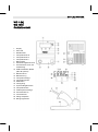
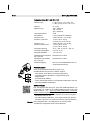
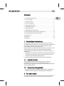
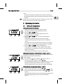
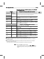
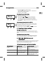
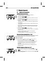
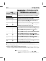
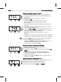
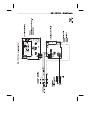
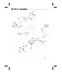
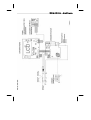
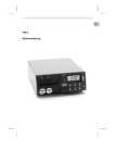
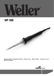
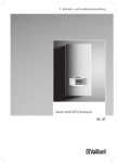
Geräteübersicht
1
2
3
4
5
6
7
8
9
10
11
12
13
14
15
16
17
18
19
20
21
22
23
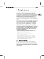
Display
UP-Taste
DOWN-Taste
Temperaturtaste III
Temperaturtaste II
Temperaturtaste I
Netzschalter
Potentialausgleichsbuchse
Anschlussbuchse für das
Lötwerkzeug
USB-Schnittstelle, B-Mini
(WD 1M optional)
Netzanschluss
Netzsicherung
Temperaturanzeige
Temperatursymbol
Zeitfunktion
Verriegelung
Optische Regelkontrolle
Temperaturtasten
Festtemperaturanzeige
Sonderfunktionen
Trichtereinsatz
Ablage Lötspitzen
Reinigungseinsatz
3 Lieferumfang ............................................................................ 4
4 Gerätebeschreibung ................................................................ 4
5 Gerät in Betrieb nehmen .......................................................... 7
6 Gerät bedienen ........................................................................ 7
7 Sonderfunktionen ..................................................................... 9
8 Zurücksetzen auf Werkseinstellungen ...................................... 15
EN
FR
2 Zu Ihrer Sicherheit ................................................................... 4
IT
1 Zu dieser Anleitung .................................................................. 3
ES
Inhalt
DE
3-16
PT
WD 1 (M) / WD 1000
Lesen Sie diese Anleitung und die beiliegenden Sicherheitshinweise
vor Inbetriebnahme des Gerätes vollständig bevor Sie mit der
Lötstation WD 1 (M) / WD 1000 arbeiten.
Bewahren Sie diese Anleitung so auf, dass sie für alle Benutzer
zugänglich ist.
1.1
Berücksichtigte Richtlinien
Die Weller mikroprozessorgeregelte Lötstation WD 1 (M) / WD 1000
entspricht den Angaben der EG Konformitätserklärung mit den
Richtlinien 2004/108/EG, 2006/95/EG und 2011/65/EU (RoHs).
1.2
Mitgeltende Dokumente
Betriebsanleitung der Lötstation WD 1 (M) / WD 1000
Begleitheft Sicherheitshinweise zu dieser Anleitung
SV
DK
FI
GR
TR
CZ
PL
Diese Anleitung enthält wichtige Informationen, um die Lötstation
WD 1 (M) / WD 1000 sicher und sachgerecht in Betrieb zu nehmen,
zu bedienen, zu warten und einfache Störungen selbst zu
beseitigen.
HU
Wir danken Ihnen für das mit dem Kauf der Weller
WD 1 (M) / WD 1000 erwiesene Vertrauen. Bei der Fertigung
wurden strengste Qualitätsanforderungen zugrunde gelegt, die eine
einwandfreie Funktion des Gerätes sicherstellen.
SK
1 Zu dieser Anleitung
SL
13 Garantie ................................................................................... 16
EE
12 Entsorgung .............................................................................. 16
LV
11 Zubehör ................................................................................... 16
LT
10 Fehlermeldungen und Fehlerbehebung.................................... 15
NL
9 WD 1 (M) / WD 1000 pflegen und warten ................................. 15
4-16
WD 1 (M) / WD 1000
2 Zu Ihrer Sicherheit
Die Lötstation WD 1 (M) / WD 1000 wurde entsprechend dem
heutigen Stand der Technik und den anerkannten
sicherheitstechnischen Regeln hergestellt. Trotzdem besteht die
Gefahr von Personen- und Sachschäden, wenn Sie die
Sicherheitshinweise im beiliegenden Sicherheitsheft sowie die
Warnhinweise in dieser Anleitung nicht beachten. Geben Sie die
Lötstation WD 1 (M) / WD 1000 an Dritte stets zusammen mit der
Betriebsanleitung weiter.
2.1
Bestimmungsgemäßer Gebrauch
Verwenden Sie die Lötstation WD 1 (M) / WD 1000 ausschließlich
gemäß dem in der Bedienungsanleitung angegebenen Zweck zum
Löten und Entlöten unter den hier angegebenen Bedingungen. Der
bestimmungsgemäße Gebrauch der Lötstation WD 1 (M) / WD 1000
schließt auch ein, dass
Sie diese Anleitung beachten,
Sie alle weiteren Begleitunterlagen beachten,
Sie die nationalen Unfallverhütungsvorschriften am Einsatzort
beachten.
Für eigenmächtig vorgenommene Veränderungen am Gerät wird
vom Hersteller keine Haftung übernommen.
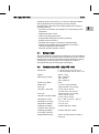
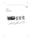
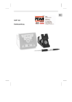
3 Lieferumfang
WD 1
WD 1000 WD 1M
Steuergerät
Netzkabel
Klinkenstecker
Lötkolben
Sicherheitsablage
Betriebsanleitung
Heft
Sicherheitshinweise
4 Gerätebeschreibung
Die Weller WD 1 (M) / WD 1000 ist eine vielseitig verwendbare
Lötstation für professionelle Reparaturarbeiten an elektronischen
Baugruppen neuester Technologie in der industriellen
Fertigungstechnik sowie im Reparatur- und Laborbereich.
Die digitale Regelelektrotechnik gewährleistet zusammen mit einer
hochwertigen Sensor- und Wärmeübertragungstechnik im
Lötwerkzeug ein präzises Temperaturregelverhalten an der
Lötspitze. Die schnelle Messwerterfassung sorgt für höchste
Temperaturgenauigkeit und ein optimales dynamisches
Temperaturverhalten im Belastungsfall.
EN
FR
IT
ES
PT
NL
SV
DK
FI
GR
TR
CZ
PL
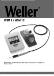
Der Trichtereinsatz (21) für den Lötkolben ist 4-fach verstellbar und
kann werkzeuglos in die ergonomisch günstigste Position gebracht
werden. Rückseitig befinden sich Ablagemöglichkeiten (22) für die
Lötspitze. Die Fußplatte der Ablage beinhaltet einen
Reinigungseinsatz (23) zur Lötspitzenreinigung.
HU
Sicherheitsablage
SK
4.1
SL
Die Weller WD 1 (M) / WD 1000 Lötstation bietet folgende weitere
Funktionen:
Automatische Werkzeugerkennung und Aktivierung der
entsprechenden Regelparameter
Digitale Temperaturregelung
Eingabemöglichkeit von Offset-Werten
Programmierbare Temperaturabsenkung (Setback)
Standby- und Verriegelungsfunktion
Antistatische Ausführung des Gerätes nach ESD-Sicherheit
Verschiedene Potentialausgleichsmöglichkeiten am Gerät
(Standardkonfiguration hart geerdet)
Kundenspezifische Kalibrierfunktion
EE
Soll- und Ist-Wert werden digital angezeigt. Drei Temperaturtasten
dienen zur direkten Anwahl von Festtemperaturen. Das Erreichen
der vorgewählten Temperatur wird durch Blinken der optischen
Regelkontrolle („“ Symbol im Display) signalisiert.
LV
An die WD 1 können alle Lötkolben (außer Microtools) bis 80 Watt
angeschlossen werden. Der Temperaturbereich liegt bei
50 °C – 450 °C (150 °F – 850 °F).
Die WD 1M ist Multifunktional es können alle Lötkolben bis 150 Watt
und Microtools (WMRP & WMRT) angeschlossen werden, der
Temperaturbereich liegt bei 50 °C – 450 °C (150 °F – 850 °F).
DE
5-16
LT
WD 1 (M) / WD 1000
6-16
WD 1 (M) / WD 1000
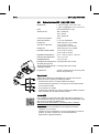
Technische Daten WD 1 (M) / WD 1000
Abmessungen
L x B x H (mm): 134 x 108 x 147
L x B x H (inch): 5,27 x 4,27 x 5,77
Gewicht
ca. 3,4 kg
Netzspannung
230 V, 50/60 Hz
120 V, 60 Hz
100 V, 50/60 Hz
Leistungsaufnahme
95 W
Schutzklasse
I und III, Gehäuse antistatisch
Sicherung (12)
Nur WD 1 / WD 1000
T 500 mA (230 V, 50 / 60 Hz)
T 1,0 A (120 V, 60 Hz)
T 1,25 A (100 V, 50 / 60 Hz)
Sicherung (12)
Nur WD 1 M/ WD 1000
T 800 mA (230 V, 50 / 60 Hz)
T 1,6 A (120 V, 60 Hz)
T 1,6 A (100 V, 50 Hz)
Temperaturregelung
50 °C – 450 °C (150 °F – 842 °F)
Temperaturgenauigkeit
± 9 °C (± 17 °F)
Temperaturstabilität
± 5 °C (± 9 °F)
Ableitwiderstand Lötspitze
(tip to ground)
Entspricht IPC-J-001D
Ableitspannung Lötspitze
(tip to ground)
Entspricht IPC-J-001D
Potentialausgleich
Über 3,5 mm Schaltklinkenbuchse an
der Geräteunterseite (8).
Potentialausgleich
Durch unterschiedliche Beschaltung der 3,5 mm
Schaltklinkenbuchse (8) sind 4 Varianten möglich:
Hart geerdet: Ohne Stecker (Auslieferungszustand).
Potentialausgleich: Mit Stecker, Ausgleichsleitung am
Mittelkontakt.
Potentialfrei: Mit Stecker
Weich geerdet: Mit Stecker und eingelötetem Widerstand. Erdung
über den gewählten Widerstand
USB-Schnittstelle
Das Steuergeräte WD 1M ist mit einer Mini USB-Schnittstelle (10)
ausgerüstet. Zur Nutzung der USB-Schnittstelle steht Ihnen eine
Weller-Software auf http://www.weller.de/en/Weller---DownloadCenter--Software-Updates.html zur Verfügung mit der Sie
ein Software Update („Firmware Updater“) an Ihrem Steuergerät
durchführen können und
das Steuergerät fernbedienen, sowie Temperaturkurven grafisch
darstellen, speichern und ausdrucken können („Monitorsoftware“).
Hinweis
Die Steuergeräte WD 1 und WD 1M können mit einer USBSchnittstelle nachgerüstet werden (siehe Zubehör).
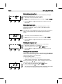
5.
6.
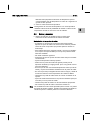
Nach dem Einschalten des Gerätes führt der Mikroprozessor einen
Selbsttest durch, in dem alle Anzeigeelemente kurzzeitig in Betrieb
sind. Anschließend wird kurzzeitig die eingestellte Temperatur
(Sollwert) und die Temperaturversion (°C / °F) angezeigt. Danach
schaltet die Elektronik automatisch auf die Istwertanzeige. Das
Symbol „ „(17) erscheint im Display (1) als optische
Regelkontrolle:
Konstantes Leuchten bedeutet, dass das System aufheizt.
Blinken signalisiert das Erreichen der vorgewählten Temperatur.
Die an das WD 1 (M) / WD 1000 anschließbaren Werkzeuge
entnehmen Sie bitte der Zubehörliste auf der Seite 16.
6 Gerät bedienen
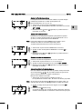
6.1
Temperatur einstellen
Temperatur individuell einstellen
EN
FR
IT
ES
PT
NL
SV
DK
FI
Das Display zeigt den Temperatur-Istwert an.
2. Die Taste UP oder DOWN drücken.
LV
1. Gerät am Netzschalter (7) einschalten.
Das Display schaltet auf den eingestellten Sollwert um. Das
Temperatursymbol (14) blinkt.
3. Die Taste UP oder DOWN drücken, um die gewünschte
Solltemperatur einzustellen:
- Kurzes Tippen verstellt den Sollwert um ein Grad.
LT
Hinweis
GR
3.
4.
Lötwerkzeug mit Anschlussstecker in die Anschlussbuchse (9)
des Steuergeräts einstecken und durch kurze Rechtsdrehung
verriegeln.
Das Lötwerkzeug in der Sicherheitsablage ablegen.
Überprüfen, ob die Netzspannung mit der Angabe auf dem
Typenschild übereinstimmt und der Netzschalter (7) sich in
ausgeschaltetem Zustand befindet.
Das Steuergerät mit dem Netz verbinden (11).
Das Gerät am Netzschalter (7) einschalten.
TR
1. Das Gerät sorgfältig auspacken.
2. Die Lötwerkzeuge wie folgt anschließen:
CZ
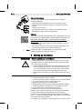
Legen Sie das Lötwerkzeug bei Nichtgebrauch immer in der
Sicherheitsablage ab.
PL
Lesen Sie die beiliegenden Sicherheitshinweise, die
Sicherheitshinweise dieser Betriebsanleitung sowie die
Anleitung Ihres Steuergeräts vor in Betriebnahme des
Steuergeräts vollständig durch und beachten Sie die darin
gegebenen Vorsichtsmaßnahmen.
HU
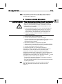
Durch unsachgemäßes Anschließen des Steuergeräts besteht
Verletzungsgefahr und kann das Gerät beschädigt werden. Beim
Betrieb des Steuergeräts besteht Verbrennungsgefahr am
Lötwerkzeug.
SK
WARNUNG! Stromschlag und Verbrennungsgefahr
SL
5 Gerät in Betrieb nehmen
DE
7-16
EE
WD 1 (M) / WD 1000
8-16
WD 1 (M) / WD 1000
- Permanentes Drücken verstellt den Sollwert im
Schnelldurchlauf.
Ca. 2 Sekunden nach Loslassen der Einstelltasten erscheint im
Display wieder der Istwert des ausgewählten Kanals.
4. Taste UP und DOWN gleichzeitig drücken.
Ist der Kanal nun inaktiv, erscheint im Display die Anzeige „OFF“.
Ist der Kanal nun aktiviert, erscheint im Display die aktuelle
Isttemperatur.
Gespeicherte Daten gehen durch das Ausschalten eines Kanals
nicht verloren.
Temperatur mit Temperaturtasten I, II und III anwählen
Der Temperatursollwert kann durch die Anwahl von drei
voreingestellten Temperaturwerten (Festtemperaturen) eingestellt
werden.
Werksseitige Einstellungen:
I = 150 °C (300 °F), II = 350 °C (662 °F), III = 380 °C (716 °F)
Gewünschte Temperaturtaste I, II oder III drücken.
Der gewählte Sollwert wird für ca. 2 s im Display angezeigt.
Während der Sollwertanzeige blinkt das Temperatursymbol.
Anschließend schaltet das Display automatisch wieder zur
Istwertanzeige zurück.
Temperaturwert der Temperaturtasten I, II und III einstellen
1. Gewünschte Temperaturtaste I, II oder III drücken.
2. Temperatursollwert mit Taste UP oder DOWN einstellen.
3. Gewünschte Temperaturtaste I, II oder III drei Sekunden lang
gedrückt halten.
Währenddessen blinkt die Temperaturanzeige für den
entsprechenden Temperaturwert. Nach 3 Sekunden wird der
eingestellte Wert gespeichert.
4. Temperaturtaste wieder loslassen.
Hinweis
Die Belegung einer Temperaturtaste mit einer niedrigen „Setback“Temperatur bietet die Möglichkeit der manuellen
Temperaturabsenkung bei Nichtgebrauch des Lötkolbens.
6.2
Löten und Entlöten
Führen Sie die Lötarbeiten gemäß der Betriebsanleitung Ihres
angeschlossenen Lötwerkzeuges durch.
Behandlung der Lötspitzen
Benetzen Sie beim ersten Aufheizen die selektive und verzinnbare
Lötspitze mit Lot. Dies entfernt lagerbedingte Oxydschichten und
Unreinheiten der Lötspitze.
Achten Sie bei Lötpausen und vor dem Ablegen des Lötkolbens
darauf, dass die Lötspitze gut verzinnt ist.
Verwenden Sie keine zu aggressiven Flussmittel.
Achten Sie immer auf den ordnungsgemäßen Sitz der Lötspitzen.
Wählen Sie die Arbeitstemperatur so niedrig wie möglich.
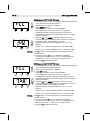
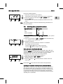
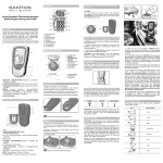
7.1
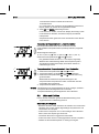
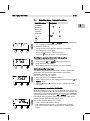
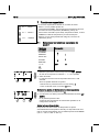
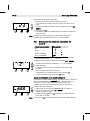
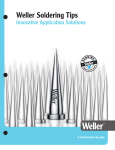
Sonderfunktionen Menü 1 auswählen
Sonderfunktionen
EN
FR
IT
DK
FI
CZ
I
SETBACK
AUTO OFF
II
OFFSET
WINDOW
°C / °F
GR
Navigation
STANDBY
PL
ON/OFF
EXIT
III
HU
1x ➾
SK
Menü 2
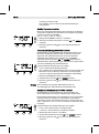
1. Taste UP und DOWN gleichzeitig gedrückt halten.
Nach 2 s erscheint im Display die Anzeige „– 1 –“.
2. Tasten loslassen.
Die Auswahl der Sonderfunktionen des Menüs 1 ist aktiviert.
Die Einstellungen können nun vorgenommen werden.
- Mit Tasten I, II Menüpunkte auswählen.
- Mit Taste III Menü wieder verlassen (EXIT).
Zurücksetzen der Sonderfunktionen auf die Werkseinstellungen
1. Taste III drücken und gedrückt halten.
2. Anschließend die Tasten UP und DOWN gleichzeitig drücken.
SL
4s➾
Die Sonderfunktionen sind in 2 Menüebenen eingeteilt:
Menü 1 mit Einstellungsmöglichkeiten für
Standby-Temperatur, Temperaturabschaltung (Setback),
Automatische Abschaltzeit (Auto-OFF), Temperatur-Offset,
Window-Funktion, Temperatureinheiten und
Verriegelungsfunktion.
Menü 2 mit Einstellungsmöglichkeiten für ID Code,
Kalibrierungsfunktion (FCC).
EE
Menü 1
LV
2s➾
TR
7 Sonderfunktionen
SV
NL
Die Steuergeräte wurden für eine mittlere Lötspitzengröße justiert.
Abweichungen durch Spitzenwechsel oder der Verwendung von
anderen Spitzenformen können entstehen.
LT
Hinweis
ES
Wählen Sie die für die Anwendung größtmögliche Lötspitzenform
Daumenregel: ca. so groß wie das Lötpad
Sorgen Sie für einen großflächigen Wärmeübergang zwischen
Lötspitze und Lötstelle, indem Sie die Lötspitze gut verzinnen.
Schalten Sie bei längeren Arbeitspausen das Lötsystem aus oder
verwenden Sie die Weller Funktion zur Temperaturabsenkung bei
Nichtgebrauch
Benetzen Sie die Spitze, bevor Sie den Lötkolben in die Ablage
legen.
Geben Sie das Lot direkt auf die Lötstelle, nicht auf die Lötspitze.
Wechseln Sie die Lötspitzen mit dem dazugehörigen Werkzeug.
Üben Sie keine mechanische Kraft auf die Lötspitze aus.
DE
9-16
PT
WD 1 (M) / WD 1000
10-16
WD 1 (M) / WD 1000
Im Display erscheint „FSE“.
Die Lötstation ist nun wieder auf die Werkseinstellungen
zurückgesetzt.
Standby-Temperatur einstellen
Nach einer Temperaturabschaltung wird automatisch die StandbyTemperatur eingestellt. Die Isttemperatur wird blinkend angezeigt.
Im Display erscheint „STANDBY“
(100 °C – 300 °C / 200 °F – 600 °F).
1. Menüpunkt STANDBY im Menü 1 auswählen.
2. Sollwert für Standby-Temperatur mit Taste UP oder DOWN
einstellen.
3. Mit Taste I (zurück) oder II (vor) zum nächsten Menüpunkt
wechseln.
Temperaturabschaltung (SETBACK) einstellen
Bei Nichtgebrauch des Lötwerkzeugs wird die Temperatur nach
Ablauf der eingestellten Setback-Zeit auf Standby-Temperatur
abgesenkt. Der Setbackzustand wird durch eine blinkende
Istwertanzeige angezeigt und im Display wird „STANDBY“
angezeigt. Drücken der Taste UP oder DOWN beendet diesen
Setbackzustand. Werkzeugabhängig deaktiviert der Fingerschalter
oder die Schaltablage den Setback-Zustand.
Folgende Setback-Einstellungen sind möglich:
„0 min“: Setback OFF (Werkseinstellung)
„ON“: Setback ON (mit Schaltablage wird nach dem Ablegen des
Lötkolbens sofort auf Standby-Temperatur heruntergeregelt).
„1-99 min“: Setback ON (individuell einstellbare Setback-Zeit)
1. Menüpunkt SETBACK im Menü 1 auswählen.
2. Setback-Wert mit Taste UP oder DOWN einstellen.
3. Mit Taste I (zurück) oder II (vor) zum nächsten Menüpunkt
wechseln.
Hinweis
Bei Lötarbeiten mit geringem Wärmebedarf kann die
Zuverlässigkeit der Setbackfunktion beeinträchtigt sein..
Automatische Abschaltzeit (AUTO-OFF) einstellen
Bei Nichtgebrauch des Lötwerkzeugs wird nach Ablauf der
AUTO-OFF-Zeit die Heizung des Lötwerkzeuges abgeschaltet.
Die Temperaturabschaltung wird unabhängig von der eingestellten
Setback-Funktion ausgeführt. Die Isttemperatur wird blinkend
angezeigt und dient als Restwärmeanzeige. Im Display erscheint
„OFF“. Unterhalb von 50 °C (150 °F) erscheint ein blinkender Strich
im Display.
Folgende AUTO-OFF-Zeit-Einstellungen sind möglich:
„0 min“: AUTO-OFF-Funktion ist ausgeschaltet.
„1-999 min“: AUTO-OFF-Zeit, individuell einstellbar.
1. Menüpunkt OFF im Menü 1 auswählen.
2. AUTO-OFF-Zeitsollwert mit Taste UP oder DOWN einstellen.
3. Mit Taste I (zurück) oder II (vor) zum nächsten Menüpunkt
wechseln.
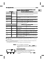
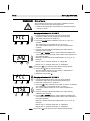
Einstellungen
Temperaturverhalten ohne Schaltablage
SETBACK
OFF Time
Time [1-99 min] [1-999 min]
Lötwerkzeug wird in der Ablage3) auf die STANDBY-Temperatur2)
heruntergeregelt.
0
Time
Lötwerkzeug wird in der Ablage3) nach Ablauf der OFF-Zeit
abgeschaltet.
ON
Time
Lötwerkzeug wird in der Ablage3) auf die STANDBY-Temperatur2)
heruntergeregelt und wird nach Ablauf der OFF-Zeit abgeschaltet.
Time
0
Lötwerkzeug wird in der Ablage3) nach der SETBACK-Zeit auf die
STANDBY-Temperatur2) heruntergeregelt.
Time
Lötwerkzeug wird in der Ablage3) nach Ablauf der SETBACK-Zeit
auf die STANDBY-Temperatur2) heruntergeregelt, und nach Ablauf
der OFF-Zeit abgeschaltet.
Time
1)
Nichtgebrauch = kein Drücken der UP/DOWN-Tasten und kein Temperaturabfall > 3 °C.
2)
STANDBY-Temperatur muss unter der eingestellten Solltemperatur liegen, sonst ist die SETBACKFunktion inaktiv.
3)
Wenn eine Schaltablage angeschlossen ist, bleibt das Lötwerkzeug außerhalb der Ablage immer
auf der eingestellten Solltemperatur.
Die Ablagefunktion wird nach dem ersten Ablegen des Lötwerkzeugs aktiviert
Hinweis
Reset von STANDBY- und OFF-Modus:
Ohne Schaltablage durch Drücken der UP- oder DOWN-Taste.
Mit Schaltablage durch Entnehmen des Lötwerkzeugs aus der
Ablage.
Temperatur-Offset einstellen
Die reale Lötspitzentemperatur kann durch Eingabe eines
Temperatur-Offsets um ± 40 °C (± 72 °F) angepasst werden.
1. Menüpunkt OFFSET im Menü 1 auswählen.
2. Auto-OFFSET-Temperaturwert mit Taste UP oder DOWN
einstellen.
NL
PT
ES
IT
0
SV
ON
DK
Lötwerkzeug wird in der Ablage3) abgeschaltet.
FI
0
GR
0
TR
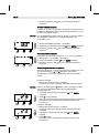
Temperaturverhalten mit Schaltablage
CZ
Time
Lötwerkzeug wird bei Nichtgebrauch1) nach Ablauf der SETBACKZeit auf die STANDBY-Temperatur2) heruntergeregelt und wird nach
Ablauf der OFF-Zeit abgeschaltet.
PL
Lötwerkzeug wird bei Nichtgebrauch1) nach Ablauf der SETBACKZeit auf die STANDBY-Temperatur2) heruntergeregelt.
HU
Time
0
SK
Time
Lötwerkzeug wird bei Nichtgebrauch1) nach Ablauf der OFF-Zeit
abgeschaltet.
SL
ON
Time
EE
0
Lötwerkzeug bleibt auf der eingestellten Löttemperatur.
0
LV
ON
LT
0
EN
Temperaturverhalten bei unterschiedlichen Einstellungen der
SETBACK- und AUTO OFF-Funktionen
DE
11-16
FR
WD 1 (M) / WD 1000
12-16
WD 1 (M) / WD 1000
3. Mit Taste I (zurück) oder II (vor) zum nächsten Menüpunkt
wechseln.
Window-Funktion einstellen
Ausgehend von einer eingestellten, verriegelten Temperatur, kann
mit Hilfe der WINDOW-Funktion ein Temperaturfenster von ± 99 °C
(± 180 °F) eingestellt werden.
Hinweis
Um die WINDOW-Funktion nutzen zu können, muss die Lötstation
im verriegelten Zustand (siehe „Verriegelungsfunktion ein/ausschalten“) sein.
1. Menüpunkt WINDOW im Menü 1 auswählen.
2. WINDOW-Temperaturwert mit Taste UP oder DOWN einstellen.
3. Mit Taste I (zurück) oder II (vor) zum nächsten Menüpunkt
wechseln.
Temperatureinheit umstellen
Umschalten der Temperatureinheit von °C in °F oder umgekehrt.
1. Menüpunkt °C / °F im Menü 1 auswählen.
2. Temperatureinheit mit Taste UP oder DOWN einstellen.
3. Mit Taste I (zurück) oder II (vor) zum nächsten Menüpunkt
wechseln.
Verriegelungsfunktion ein-/ausschalten
Nach Einschalten der Verriegelung sind an der Lötstation nur noch
die Temperaturtasten I, II und III bedienbar. Alle anderen
Einstellungen können bis zur Entriegelung nicht mehr verstellt
werden.
Lötstation verriegeln:
1. Menüpunkt LOCK im Menü 1 auswählen.
Im Display wird „OFF“ angezeigt. Das Schlüsselsymbol blinkt.
Hinweis
Drücken der Tasten I oder II während „OFF“ angezeigt wird, führt
zum Verlassen des Menüpunktes ohne abgespeicherten
Verriegelungscode.
2. 3-stelligen Verriegelungscode mit Taste UP oder DOWN
einstellen.
3. Taste III 5 s lang drücken.
Der Code wird gespeichert. Das Schlüsselsymbol wird angezeigt.
Die Station ist nun verriegelt. Die Anzeige wechselt in das
Hauptmenü.
Lötstation entriegeln:
1. Menüpunkt LOCK im Menü 1 auswählen.
Im Display wird „ON“ angezeigt. Das Schlüsselsymbol wird
angezeigt.
2. 3-stelligen Verriegelungscode mit Taste UP oder DOWN
eingeben.
3. Taste III drücken.
Die Station ist nun entriegelt. Die Anzeige wechselt in das
Hauptmenü.
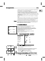
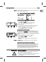
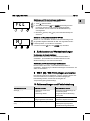
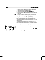
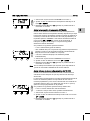
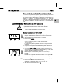
Sonderfunktionen Menü 2 auswählen
III
EXIT
HI / LO CONROL
1. Gewünschten Kanal I, II oder III für die Eingabe der
Sonderfunktionen auswählen.
2. Tasten UP- und DOWN gleichzeitig gedrückt halten.
Nach 4 s erscheint im Display die Anzeige „– 2 –“.
3. Tasten loslassen.
Die Auswahl der Sonderfunktionen des Menüs 2 ist aktiviert.
Die Einstellungen können nun vorgenommen werden.
- Mit Tasten I und II Menüpunkte auswählen.
- Mit Taste III Menü wieder verlassen (EXIT).
IT
II
ES
AUTO CHANNEL
I
PT
FCC
FR
Navigation
ID
NL
Sonderfunktionen
SV
7.2
DE
Das Entriegeln der Lötstation ist auch mit Hilfe einer Dekodierliste
oder dem Reset-Stecker möglich.
DK
Hinweis
13-16
EN
WD 1 (M) / WD 1000
Taste III drücken, um den Menüpunkt ohne Veränderungen zu
verlassen (EXIT).
GR
TR
CZ
PL
Hinweis
HU
Bei Verwendung der optionalen USB-Schnittstelle können mehrere
WD 1 (M) / WD 1000 Lötstationen in vollem Funktionsumfang
angesteuert und fernbedient werden. Jede Station benötigt hierfür
eine Stationskennung (ID Code) um eindeutig identifiziert werden zu
können.
1. Menüpunkt REMOTE ID im Menü 2 auswählen.
2. Mit Taste UP oder DOWN eine ID eingeben
(Mögliche Werte 0 – 999).
3. Mit Taste I (zurück) oder II (vor) zum nächsten Menüpunkt
wechseln.
FI
Stationskennung (ID Code) einstellen
Das Lötwerkzeug wird während des Kalibriervorgangs heiß. Es
besteht Verbrennungsgefahr bei Berührung.
Berühren Sie nicht das heiße Lötwerkzeug und bringen Sie keine
brennbaren Gegenstände in die Nähe des heißen
Lötwerkzeugs.
SL
EE
LV
WARNUNG! Verbrennungsgefahr
LT
Mit der FCC-Funktion können Sie die Temperaturgenauigkeit der
Lötstation überprüfen und eventuelle Abweichungen ausgleichen.
Hierfür muss die Lötspitzentemperatur mit einem externen
Temperaturmessgerät und einer dem Lötwerkzeug zugeordneten
Temperaturmessspitze gemessen werden. Vor der Kalibrierung
muss der entsprechende Kanal angewählt werden.
SK
Kalibrierfunktion (Factory Calibration Check) bedienen
14-16
WD 1 (M) / WD 1000
Kalibrierung bei 100 °C / 212 °F ändern
1. Temperaturfühler (0,5 mm) des externen Temperaturmessgeräts
in die Temperaturmessspitze einführen.
2. Menüpunkt FCC im Menü 2 auswählen.
3. Taste DOWN drücken.
Kalibrierpunkt 100 °C / 212 °F wird ausgewählt.
Die Lötspitze wird nun auf 100 °C / 212 °F aufgeheizt.
Regelkontrolle blinkt, sobald die Temperatur konstant ist.
4. Angezeigte Temperaturen des Messgerätes mit der Anzeige im
Display vergleichen.
5. Mit Taste UP oder DOWN die Differenz zwischen dem am
externen Messgerät angezeigten Wert und dem an der Station
angezeigten Wert an der Lötstation einstellen.
Maximal möglicher Temperaturabgleich ± 40 °C (± 72 °F).
Beispiel:
Display 100 °C, externes Messgerät 98 °C: Einstellung 2
Display 100 °C, externes Messgerät 102 °C: Einstellung 2
Hinweis
Taste III drücken, um den Menüpunkt ohne Veränderungen zu
verlassen (EXIT).
6. Drücken der Taste II (Set), um den Wert zu bestätigen.
Die Temperaturabweichung ist nun auf 0 zurückgesetzt. Die
Kalibrierung bei 100 °C / 212 °F ist nun abgeschlossen.
7. Mit Taste III das Menü 2 verlassen.
Kalibrierung bei 450 °C / 842 °F ändern
1. Temperaturfühler (0,5 mm) des externen Temperaturmessgeräts
in die Temperaturmessspitze einführen.
2. Menüpunkt FCC im Menü 2 auswählen.
3. Taste UP drücken.
Kalibrierpunkt 450 °C / 842 °F wird ausgewählt.
Die Lötspitze wird nun auf 450 °C / 842 °F aufgeheizt.
Die Regelkontrolle blinkt, sobald die Temperatur konstant ist.
4. Angezeigte Temperaturen des Messgerätes mit der Anzeige im
Display vergleichen.
5. Mit Taste UP oder DOWN die Differenz zwischen dem am
externen Messgerät angezeigten Wert und dem an der Station
angezeigten Wert an der Lötstation einstellen.
Maximal möglicher Temperaturabgleich ± 40 °C (± 72 °F).
Beispiel:
Display 450 °C, externes Messgerät 448 °C: Einstellung 2
Display 450 °C, externes Messgerät 452 °C: Einstellung 2
Hinweis
Taste III drücken, um den Menüpunkt ohne Veränderungen zu
verlassen (EXIT).
6. Drücken der Taste II (Set), um den Wert zu bestätigen.
Die Temperaturabweichung ist nun auf 0 zurückgesetzt. Die
Kalibrierung bei 450 °C / 842 °F ist nun abgeschlossen.
7. Mit Taste III das Menü 2 verlassen.
Diese Funktion wird unter „7.2 Sonderfunktionen Menü 2
auswählen“, „Kalibrierung auf Werkseinstellungen zurücksetzen“ auf
Seite 12 beschrieben.
9 WD 1 (M) / WD 1000 pflegen und warten
Der Übergang zwischen Heizkörper / Sensor und der Lötspitze darf
nicht durch Schmutz, Fremdkörper oder Beschädigungen
beeinträchtigt werden, da dies die Genauigkeit der
Temperaturregelung beeinträchtigt.
10 Fehlermeldungen und Fehlerbehebung
Meldung/Symptom
Mögliche Ursache
Maßnahmen zur Abhilfe
Anzeige „- - -“
Werkzeug wurde nicht
erkannt
Werkzeug defekt
Anschluss des Werkzeugs am
Gerät überprüfen
Angeschlossenes Werkzeug
überprüfen
Anzeige "tip"
Lötspitze des Microtools nicht
richtig eingesteckt oder defekt
Lötspitze erneut einstecken
Defekte Lötspitze tauschen
Keine Displayfunktion (Display keine Netzspannung vorhanden Netzschalter einschalten
aus)
Netzspannung überprüfen
Gerätesicherung überprüfen
EN
FR
IT
ES
PT
NL
SV
DK
FI
GR
Kalibrierung auf Werkseinstellungen zurücksetzen
TR
Diese Funktion wird unter „7.1 Sonderfunktionen Menü 1
auswählen“, „Zurücksetzen der Sonderfunktionen auf die
Werkseinstellungen“ auf Seite 9 beschrieben.
CZ
Zurücksetzen der Sonderfunktionen
PL
8 Zurücksetzen auf Werkseinstellungen
HU
eingestellte Regelcharakteristik für WP 120 eingestellt werden:
1. Menüpunkt HI / LO im Menü 2 auswählen.
2. Status mit Taste UP (HI) oder DOWN (LO) einstellen.
SK
Mit der HI / LO CONTROL-Funktion kann die werkseitig auf HI
SL
Einstellen der Regelcharakteristik für WP 120
EE
1. Menüpunkt FCC im Menü 2 auswählen.
2. Taste III gedrückt halten.
3. Anschließend Tasten UP und DOWN gleichzeitig drücken.
Im Display erscheint „FSE“ (Factory Setting Enabled).
Die Lötstation ist nun wieder auf die Werkskalibrierung
zurückgesetzt.
4. Mit Taste I (zurück) oder II (vor) zum nächsten Menüpunkt
wechseln.
LV
Kalibrierung auf Werkseinstellungen zurücksetzen
DE
15-16
LT
WD 1 (M) / WD 1000
16-16
WD 1 (M) / WD 1000
11 Zubehör
T005 13 841 99
T005 15 125 99
T005 15 161 99
T005 15 162 99
T005 27 028 99
T005 27 040 99
T005 29 181 99
T005 29 178 99
T005 29 179 99
T005 29 188 99
T005 33 133 99
T005 87 597 28
T005 87 597 27
T005 31 185 99
Spiralwolle für WDC 2
WDC 2 Trockenreinigungseinsatz
WDH 10T Schaltablage WSP 80/WP 80
WDH 20T Schaltablage für WMP
WHP 80 Vorheizplatte
WSB 80 Lötbad, 80 W
WP 80 Lötkolbenset, 80 W
WSP 80 Lötkolbenset
WMP Lötkolbenset
LR 82 Lötkolbenset
WTA 50 Entlötset
Reset-Stecker °C
Reset-Stecker °F
USB Erweiterungsmodul
Nur für M-Version
T005 13 173 99
T005 27 042 99
T005 29 193 99
T005 15 121 99
T005 29 190 99
T005 29 189 99
T005 15 152 99
WMRT Entlötset
WSB 150 Lötbad, 150 W
WP 120 Lötkolben, 120 W
WDH 10 Sicherheitsablage WP 120
WMRP Lötset
WSP 150 Lötkolbenset, 150 W
WDH 30 Sicherheitsablage WSP 150
Weiteres Zubehör entnehmen Sie bitte den Betriebsanleitungen der
einzelnen Lötkolbensets.
12 Entsorgung
Entsorgen Sie ausgetauschte Geräteteile, Filter oder alte Geräte
gemäß den Vorschriften Ihres Landes.
13 Garantie
Die Mängelansprüche des Käufers verjähren in einem Jahr ab
Ablieferung an ihn. Dies gilt nicht für Rückgriffsansprüche des
Käufers nach §§ 478, 479 BGB.
Aus einer von uns abgegebenen Garantie haften wir nur, wenn die
Beschaffenheits- oder Haltbarkeitsgarantie von uns schriftlich und
unter Verwendung des Begriffs „Garantie“ abgegeben worden ist.
Technische Änderungen vorbehalten!
Die aktualisierten Betriebsanleitungen finden Sie unter
www.weller-tools.com.
EE
SL
SK
HU
PL
CZ
TR
GR
FI
DK
SV
NL
PT
ES
Operating Manual
LV
IT
FR
WD 1000
LT
WD 1 (M) /
EN
DE
WD 1 (M) / WD 1000
WD 1 (M)
WD 1000
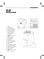
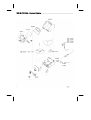
Equipment overview
1
2
3
4
5
6
7
8
9
10
11
12
13
14
15
16
17
18
19
20
21
22
Display
UP button
DOWN button
Temperature button III
Temperature button II
Temperature button I
Mains switch
Equipotential-bonding socket
Connecting socket for
soldering tool
USB interface, B-Mini
(WD 1M optional)
Mains connection
Mains system fuse
Temperature display
Temperature symbol
Time function
Lock
Optical control check
Temperature buttons
Fixed temperature display
Special functions
Funnel insert
Soldering tip compartment
23 Cleaning element
3 Scope of supply ....................................................................... 4
4 Device description.................................................................... 4
5 Starting up the device .............................................................. 6
6 Operating the device ................................................................ 7
7 Special functions ...................................................................... 8
8 Resetting to factory settings ..................................................... 15
EN
FR
2 For your safety ......................................................................... 3
IT
1 About these instructions ........................................................... 3
ES
Contents
DE
3-16
PT
WD 1 (M) / WD 1000
Read these instructions and the accompanying safety information
carefully before switching on the device and starting work with
the WD 1 (M) / WD 1000 soldering station.
Make sure that all users have access to these instructions.
1.1
Applied directives
The Weller microprocessor-controlled WD 1 (M) / WD 1000
soldering station conforms to the specifications of the EC
Declaration of Conformity with Directives 2004/108/EC, 2006/95/EC
and 2011/65/EU (RoHS).
SV
DK
FI
GR
TR
Operating instructions for soldering station WD 1 (M) / WD 1000
Safety information booklet accompanying these instructions
LV
Documents also applicable
2 For your safety
LT
1.2
CZ
These instructions contain important information for safe and correct
initial operation of the WD 1 (M) / WD 1000 soldering station,
including continued operation, maintenance and self-correction of
simple faults.
PL
Thank you for placing your trust in our company by purchasing
the Weller WD 1 (M) / WD 1000. The device has been manufactured
in accordance with the most rigorous quality standards, which
ensure that the device operates perfectly.
HU
1 About these instructions
SK
13 Warranty .................................................................................. 16
SL
12 Disposal ................................................................................... 16
EE
11 Accessories ............................................................................. 16
NL
9 WD 1 (M) / WD 1000 care and maintenance ............................ 15
10 Fault messages and fault elimination ....................................... 15
The WD 1 (M) / WD 1000 soldering station has been manufactured
in accordance with state-of-the-art technology and recognised
4-16
WD 1 (M) / WD 1000
technical safety regulations. There is nevertheless the risk of
personal injury and damage to property if you fail to observe the
safety information set out in the accompanying booklet and the
warnings given in these instructions. Always pass on the
WD 1 (M) / WD 1000 soldering station to third parties together with
these operating instructions.
2.1
Specified use
Use the WD 1 (M) / WD 1000 soldering station exclusively for the
purpose indicated in the operating instructions of soldering and
unsoldering under the conditions specified here. Specified use of the
WD 1 (M) / WD 1000 soldering station also includes
observing these operating instructions,
observing all other accompanying documentation,
observing locally applicable accident prevention regulations.
The manufacturer shall not be liable for damage resulting from
unauthorised alterations to the machine.
3 Scope of supply
WD 1
WD 1000 WD 1M
Control unit
Power cable
Jack connector
Soldering iron
Safety holder
Operating
instructions
Safety information
booklet
4 Device description
The Weller WD 1 (M) / WD 1000 is a versatile soldering station for
performing professional repair work on state-of-the-art electronic
assemblies in the industrial engineering sector as well as repair
workshops and laboratories.
Precise temperature control performance at the soldering tip is
guaranteed by the digital control electrotechnology together with
superior-quality sensor and heat-transfer technology. High-speed
measured-value acquisition provides for maximum temperature
precision and optimum dynamic temperature performance in load
situations.
All soldering irons (except for microtools) up to 80 Watts can be
connected to the WD 1. The temperature range is from 50 °C to
450 °C (150 °F to 850 °F). The WD 1M is multifunctional and all
soldering irons up to 150 Watts and microtools (WMRP & WMRT)
can be connected; the temperature range is from 50 °C to 450 °C
(150 °F to 850 °F). Setpoint and actual values are displayed in digital
from. Three temperature buttons are used to select fixed
temperatures directly.
Power consumption
95 W
Safety class
I and III, housing antistatic
Fuse (12)
T 500 mA (230 V, 50 / 60 Hz)
T 1.0 A (120 V, 60 Hz)
T 1.25 A (100 V, 50 / 60 Hz)
Only WD 1 / WD 1000
Fuse (12)
Only WD 1 M/ WD 1000M
T 800 mA (230 V, 50 / 60 Hz)
T 1.6 A (120 V, 60 Hz)
T 1.6 A (100 V, 50 Hz)
Temperature control
50 °C – 450 °C (150 °F – 842 °F)
Temperature accuracy
± 9 °C (± 17 °F)
Temperature stability
± 5 °C (± 9 °F)
Soldering tip leakage
resistance (tip to ground)
Complies with IPC-J-001D
Soldering tip leakage
current (tip to ground)
Complies with IPC-J-001D
Equipotential bonding
Via 3.5 mm pawl socket on back of
device (8).
EN
FR
IT
SV
DK
FI
GR
230 V, 50/60 Hz
120 V, 60 Hz
100 V, 50/60 Hz
TR
approx. 3.4 kg
Mains supply voltage
CZ
Weight
PL
L x W x H (mm): 134 x 108 x 147
L x W x H (inches): 5.27 x 4.27 x 5.77
HU
Dimensions
SK
Technical data WD 1 (M) / WD 1000
SL
4.2
EE
The funnel insert (21) for holding the soldering iron has four different
settings and can be adjusted to the most ergonomic position without
requiring tools. There is a compartment (22) on the back for storing
soldering tips. The base plate on the compartment contains a
cleaning element (23) for cleaning the soldering tip.
LV
Safety holder
LT
4.1
NL
The Weller WD 1 (M) / WD 1000 soldering station also offers the
following functions:
Automatic tool detection and activation of corresponding control
parameters
Digital temperature control
Option of inputting offset values
Programmable temperature reduction (setback)
Standby and lock functions
Antistatic device design in accordance with ESD safety
Different equipotential-bonding possibilities on the device
(standard configuration hard earthed)
Customer-specific calibration function
ES
A flashing optical control check ("" symbol on display) indicates
that the preselected tool temperature has been reached.
DE
5-16
PT
WD 1 (M) / WD 1000
6-16
WD 1 (M) / WD 1000
Equipotential bonding
4 variants are possible through connecting the 3.5 mm pawl
socket (8) differently:
Hard earthed/grounded: without connector (delivery status)
Equipotential bonding: with connector, bonding line at central
contact
Floating: with connector
Soft earthed/grounded: with connector and soldered resistor.
Earthing/grounding via the selected resistor
USB port
The control units WD 1M is fitted with a mini USB interface (10). For
the purpose of using the USB port, Weller software is available on a
http://www.weller.de/en/Weller---Download-Center--SoftwareUpdates.html with which you
can carry out a software update ("Firmware Updater“) on your
control unit and
can remote-control the control unit and graphically display, store
and print temperature curves ("Monitor Software“).
Note
Control units WD 1 and WD 1M can be retrofitted with a USB
interface (accessories section on page 18).
5 Starting up the device
WARNING! Electric shock and risk of burns
Connecting the control unit incorrectly poses a risk of injury and
damage to the device. Risk of burns from the soldering tool while
the control unit is operating.
Read the enclosed instructions, the safety instructions included
in these Operating Instructions as well as the instructions for
your control unit all the way through and observe the specified
precautionary measures before operating the control unit.
Always place the soldering tool in the safety holder when not in
use.
1. Carefully unpack the device.
2. Connect the soldering tools as follows:
3.
4.
5.
6.
Insert the soldering tool with connector into the connecting socket
(9) on the control unit and turn clockwise to lock.
Place the soldering tool in the safety holder.
Check whether the mains supply voltage matches that indicated
on the rating plate and whether mains power switch (7) is off.
Connect the control unit to the mains supply (11).
Switch on the device at the mains power switch (7).
After the device has been switched on, the microprocessor carries
out a self-test in which all the display elements are briefly in
operation. The preset temperature (setpoint) and the temperature
unit (°C / °F) are then displayed briefly. The electronics automatically
switch to the actual value display.
The symbol " " (17) appears on the display (1) as an optical control
6 Operating the device
6.1
Setting the temperature
EN
FR
Please refer to the accessories section on page 16 for a list of tools
that can be connected to the WD 1 (M) / WD 1000.
Selecting the temperature with temperature buttons I, II and III
The setpoint temperature value can be set by selecting three preset
temperature values (fixed temperatures).
Factory settings:
I = 150 °C (300 °F), II = 350 °C (662 °F), III = 380 °C (716 °F)
Press the required temperature button I, II or III.
The selected setpoint appears on the display for approx. 2 s. The
temperature symbol flashes while the setpoint is displayed.
The unit switches back to the actual value display automatically.
Setting the value of temperature buttons I, II and III
1. Press the required temperature button I, II or III.
2. Set the setpoint temperature value with the UP or DOWN button.
3. Press and hold the required temperature button I, II or III for three
seconds.
The temperature display for the corresponding temperature value
flashes during this period. The set value is stored after 3
seconds.
NL
SV
DK
FI
GR
TR
CZ
Stored data is not lost when a channel is switched off.
PL
If the channel is now inactive, "OFF“ appears in the display.
If the channel is now activated, the current actual temperature
appears in the display.
HU
4. Press the UP and DOWN buttons simultaneously.
SK
The actual value of the selected channel appears in the display
again approx. 2 seconds after the setting buttons are released.
SL
The display switches to the preset setpoint value. The
temperature symbol (14) flashes.
3. Press the UP or DOWN button to set the desired setpoint
temperature:
- Brief touching alters the setpoint value by one degree.
- Permanent pressing alters the setpoint value in rapid pass
mode.
EE
The display indicates the actual temperature value.
2. Press the UP or DOWN button.
LV
1. Switch on the device at the mains power switch (7).
PT
Setting the temperature individually
LT
Note
IT
check:
Continuous illumination indicates that the system is warming up.
Flashing light indicates that the preselected temperature has been
reached.
DE
7-16
ES
WD 1 (M) / WD 1000
8-16
WD 1 (M) / WD 1000
4. Release the temperature button again.
Note
Assigning a low "Setback“ temperature to a temperature button
offers the possibility of manual temperature reduction when the
soldering bit is not in use.
6.2
Soldering and unsoldering
Carry out the soldering work in accordance with the operating
instructions of your connected soldering tool.
Handling soldering tips
Coat the tin-plated soldering tip with solder when heating the iron
for the first time as this will remove any oxide films or impurities
from the soldering tip that have accumulated during storage.
During pauses between soldering and before storing the soldering
iron, ensure that the soldering tip is well-coated.
Do not use aggressive fluxing agents.
Always make sure that the soldering tip is seated correctly.
Select the lowest possible working temperature.
Select the largest possible soldering tip shape for the application:
approx. as large as the soldering pad
Coat the soldering tip well to ensure efficient heat transfer
between the soldering tip and soldering point.
Switch off the system if you do not intend to use the soldering iron
for longer periods or activate the Weller temperature reduction
function
Coat the tip before placing the soldering iron in the holder.
Apply the solder directly at the soldering point, not on the
soldering tip.
Change the soldering tip using an appropriate tool.
Do not subject the soldering tip to physical force.
Note
2s➾
Menu 1
4s➾
Menu 2
1x ➾
ON/OFF
The control units have been adapted to hold a medium-sized
soldering tip. Discrepancies may occur if the tip is changed or a
different shaped tip is used.
7 Special functions
The special functions are divided into 2 menu levels:
Menu 1 with options for setting the
standby temperature, temperature cut-off (setback), automatic
shut-off time (Auto OFF), temperature offset, window function,
temperature units and locking function.
Menu 2 with options for setting the ID code and calibration
function (FCC).
9-16
Selecting Menu 1 special functions
Special functions
Navigation
EN
7.1
STANDBY
I
FR
SETBACK
AUTO OFF
II
OFFSET
IT
WINDOW
EXIT
III
Selection of the special functions of Menu 1 is activated.
The settings can now be made.
- Press the I, II buttons to select menu items.
- Press the III button to exit the menu again (EXIT).
NL
SV
"– 1 –“ appears in the display after 2 s.
2. Release the buttons.
DK
1. Press and hold down the UP and DOWN buttons simultaneously.
PT
ES
°C / °F
DE
WD 1 (M) / WD 1000
GR
TR
CZ
The standby temperature is automatically set after a temperature
deactivation. The actual temperature flashes in the display.
"STANDBY" appears on the display
(100 °C – 300 °C / 200 °F – 600 °F).
1. Select the menu item STANDBY in Menu 1.
2. Set the setpoint value for the standby temperature with the UP or
DOWN button.
3. Press the I (back) or II (forwards) button to switch to the next
menu item.
PL
Setting the standby temperature
HU
"FSE“ appears in the display.
The soldering station is now reset to the factory settings.
SK
1. Press and hold down button III.
2. Then press the UP and DOWN buttons simultaneously.
FI
Resetting the special functions to the factory settings
The following setback settings are possible:
"0 min“: setback OFF (factory setting)
"ON“: setback ON (the system is controlled down to standby
temperature with the switching holder after the soldering bit is
stowed)
EE
LV
LT
When the soldering tool is not in use, the temperature is reduced to
the standby temperature after the set setback time has elapsed. The
setback state is indicated by a flashing actual value and "STANDBY“
appears in the display. Pressing the UP or DOWN button terminates
this setback state. Depending on the tool, the finger switch or the
switching holder deactivates the setback state.
SL
Setting temperature deactivation (SETBACK)
10-16
WD 1 (M) / WD 1000
"1-99 min“: setback ON (individually settable setback time)
1. Select the menu item SETBACK in Menu 1.
2. Set the setback value with the UP or DOWN button.
3. Press the I (back) or II (forwards) button to switch to the next
menu item.
Note
In the case of soldering work with low heat requirements, the
reliability of the Setback function may be impaired.
Setting the automatic switch-off time (AUTO-OFF)
When the soldering tool is not in use, heating of the soldering
tool is switched off after the AUTO-OFF time has elapsed.
Temperature deactivation is performed independently of the set
setback function.
The actual temperature flashes in the display and serves as
residual-heat indicator. "OFF“ appears in the display. A flashing
dash appears in the display below 50 °C (150 °F).
The following AUTO-OFF time settings are possible:
"0 min“: AUTO-OFF function is switched off
"1-999 min“: AUTO-OFF time, individually settable
1. Select the menu item OFF in Menu 1.
2. Set the AUTO-OFF setpoint time value with the UP or DOWN
button.
3. Press the I (back) or II (forwards) button to switch to the next
menu item.
Settings
Temperature performance without switching holder
SETBACK time OFF time
[1-99 mins]
[1-999 mins]
Soldering tool is controlled down in the holder3) to the STANDBY
temperature2).
0
Time
Soldering tool is switched off in the holder3) after the OFF time has
elapsed.
ON
Time
Soldering tool is controlled down in the holder3) to the STANDBY
temperature2) and is switched off after the OFF time has elapsed.
Time
0
Soldering tool is controlled down in the holder3) to the STANDBY
temperature2) after the SETBACK time has elapsed.
Time
Soldering tool is controlled down in the holder3) to the STANDBY
temperature2) after the SETBACK time has elapsed and is switched
off after the OFF time has elapsed.
Time
1)
Not in use = UP/DOWN buttons not pressed and no temperature drop > 3 °C.
2)
STANDBY temperature must be below the set setpoint temperature, otherwise the SETBACK
function is inactive.
3)
When a switching holder is connected, the soldering tool always remains at the set setpoint
temperature outside the holder.
The holder function is activated when the soldering tool is stowed for the first time.
Note
Reset of STANDBY and OFF modes:
without switching holder by pressing the UP or DOWN button.
with switching holder by removing the soldering tool from the
holder.
NL
PT
ES
IT
0
SV
ON
DK
Soldering is switched off in the holder3).
FI
0
GR
0
TR
Temperature performance with switching holder
CZ
Time
Soldering tool is controlled down when not in use1) to the STANDBY
temperature2) after the SETBACK time has elapsed and is switched
off after the OFF time has elapsed.
PL
Soldering tool is controlled down when not in use1) to the STANDBY
temperature2) after the SETBACK time has elapsed.
HU
Time
0
SK
Time
Soldering tool is switched off when not in use1) after the OFF time
has elapsed.
SL
ON
Time
EE
0
Soldering tool remains at the set soldering temperature.
0
LV
ON
LT
0
EN
Temperature performance with different settings of the SETBACK
and AUTO OFF functions
DE
11-16
FR
WD 1 (M) / WD 1000
12-16
WD 1 (M) / WD 1000
Setting the temperature offset
The real soldering-tip temperature can be adapted by entering a
temperature offset around ± 40 °C (± 72 °F).
1. Select the menu item OFFSET in Menu 1.
2. Set the Auto-OFFSET temperature value with the UP or DOWN
button.
3. Press the I (back) or II (forwards) button to switch to the next
menu item.
Setting the window function
It is possible, starting from a set, locked temperature, to set a
temperature window of ± 99 °C (± 180 °F) with the aid of the
WINDOW function.
Note
To be able to use the WINDOW function, ensure that the soldering
station is in the locked state (see "Switching the lock function
on/off").
1. Select the menu item WINDOW in Menu 1.
2. Set the WINDOW temperature value with the UP or DOWN
button.
3. Press the I (back) or II (forwards) button to switch to the next
menu item.
Switching the temperature unit
Switching the temperature unit from °C to °F or vice versa.
1. Select the menu item °C / °F in Menu 1.
2. Set the temperature unit with the UP or DOWN button.
3. Press the I (back) or II (forwards) button to switch to the next
menu item.
Switching the lock function on/off
Once the lock is activated, only the temperature buttons I, II and III
can be used on the soldering station. All other settings are disabled
until the repair station is unlocked again.
Lock the soldering station:
1. Select the menu item LOCK in Menu 1.
"OFF“ appears in the display. The padlock symbol flashes.
Note
Pressing the buttons I or II while "OFF“ is displayed results in the
menu item being exited without a stored lock code.
2. Set a 3-digit lock code with the UP or DOWN button.
3. Press and hold button III for 5 s.
The code is stored. The padlock symbol is displayed. The station
is now locked. The display switches to the main menu.
The soldering station can also be unlocked using a decoder list or
the reset connector.
Selecting Menu 2 special functions
III
EXIT
HI / LO CONTROL
1. Select the desired channel I, II or III for entering the special
functions.
2. Press and hold down the UP and DOWN buttons simultaneously.
"– 2 –“ appears in the display after 4 s.
3. Release the buttons.
Selection of the special functions of Menu 2 is activated.
The settings can now be made.
- Press the I and II buttons to select menu items.
- Press the III button to exit the menu again (EXIT).
EN
FR
NL
II
SV
AUTO CHANNEL
I
DK
FCC
PT
Navigation
ID
FI
Special functions
GR
7.2
TR
Note
IT
Unlock the soldering station:
1. Select the menu item LOCK in Menu 1.
"ON“ appears in the display. The padlock symbol is displayed.
2. Enter the 3-digit lock code with the UP or DOWN button.
3. Press the III button.
The station is now unlocked. The display switches to the main
menu.
DE
13-16
ES
WD 1 (M) / WD 1000
Executing the calibration function (Factory Calibration Check)
With the FCC function you can check the temperature precision of
the soldering station and compensate for possible deviations. For
this purpose, the soldering-tip temperature must be measured with
an external temperature meter and a temperature measuring tip
assigned to the soldering tool. The corresponding channel must be
selected prior to calibration.
PL
HU
SK
SL
EE
Press button III to exit the menu item without changes (EXIT).
LV
Note
LT
When the optional USB port is used, several WD 1 (M) / WD 1000
soldering stations can be activated and remote-controlled to their full
operational extent. To this end, each station requires a station
identification (ID code) so that it can clearly identified.
1. Select the menu item REMOTE ID in Menu 2.
2. Enter an ID with the UP or DOWN button
(possible values 0 – 999).
3. Press the I (back) or II (forwards) button to switch to the next
menu item.
CZ
Setting the station identification (ID code)
14-16
WD 1 (M) / WD 1000
WARNING! Risk of burns
The soldering tool becomes hot during the calibration process.
There is a risk of burns from touching the tool.
Keep the hot soldering tool well away from flammable objects
and do not touch.
Changing calibration at 100 °C / 212 °F
1. Insert the temperature sensor (0.5 mm) of the external
temperature meter into the temperature measuring tip.
2. Select the menu item FCC in Menu 2.
3. Press the DOWN button.Calibration point 100 °C / 212 °F is
selected.
The soldering tip is now heated to 100 °C / 212 °F.
The control indicator flashes as soon as the temperature is
constant.
4. Compare the temperatures indicated by the meter with the
indications in the display.
5. Use the UP or DOWN button to set the difference between the
value indicated on the external meter and the value indicated on
the soldering station.
Maximum possible temperature adjustment ± 40 °C (± 72 °F).
Example:
Display 100 °C, external meter 98 °C: setting 2
Display 100 °C, external meter 102 °C: setting 2
Note
Press button III to exit the menu item without changes (EXIT).
6. Press button II (Set) to confirm the value.
The temperature deviation is now reset to 0. Calibration at
100 °C / 212 °F is now concluded.
7. Exit Menu 2 with button III.
Changing calibration at 450 °C / 842 °F
1. Insert the temperature sensor (0.5 mm) of the external
temperature meter into the temperature measuring tip.
2. Select the menu item FCC in Menu 2.
3. Press the UP button.Calibration point 450 °C / 842 °F is selected.
The soldering tip is now heated to 450 °C / 842 °F.
The control indicator flashes as soon as the temperature is
constant.
4. Compare the temperatures indicated by the meter with the
indications in the display.
5. Use the UP or DOWN button to set the difference between the
value indicated on the external meter and the value indicated on
the soldering station.
Maximum possible temperature adjustment ± 40 °C (± 72 °F).
Example:
Display 450 °C, external meter 448 °C: setting 2
Display 450 °C, external meter 452 °C: setting 2
Note
Press button III to exit the menu item without changes (EXIT).
Setting the control characteristics for the WP 120
The HI / LO CONTROL function can be used to set the control
characteristic of the WP 120, which was set to HI in the factory:
1. Select the menu item HI / LO in Menu 2.
2. Set the status by pressing the UP (HI) or DOWN (LO) button.
8 Resetting to factory settings
10 Fault messages and fault elimination
Message/Symptom
Possible cause
Corrective measures
Display: "- - -“
Tool has not been detected
Tool defective
Check connection of tool to
device
Check connected tool
Display: "tip"
Soldering tip of microtool not
correctly inserted or defective
Insert soldering tip again
Replacing defective soldering tip
No display function (display off) No mains supply voltage
Turn on mains power switch
Check mains supply voltage
Check device fuse
EN
FR
IT
ES
TR
CZ
PL
HU
SK
Dirt and foreign objects accumulated in the join between the heating
element / sensor and the soldering tip or damage to this join may
affect the accuracy of the temperature control.
SL
9 WD 1 (M) / WD 1000 care and
maintenance
EE
This function is described under "7.2 Selecting special functions
menu 2", "Resetting calibration to factory settings" on page 12.
LV
Resetting calibration to factory settings
LT
This function is described under "7.1 Selecting special functions
menu 1", "Resetting the special functions to the factory settings" on
page 8.
GR
FI
Resetting the special functions
PT
1. Select the menu item FCC in Menu 2.
2. Press and hold button III.
3. Then press the UP and DOWN buttons simultaneously.
"FSE“ (Factory Setting Enabled) appears in the display.
The soldering station is now reset to the factory settings.
4. Press the I (back) or II (forwards) button to switch to the next
menu item.
NL
Resetting calibration to factory settings
SV
6. Press button II (Set) to confirm the value.
The temperature deviation is now reset to 0. Calibration at
450 °C / 842 °F is now concluded.
7. Exit Menu 2 with button III.
DE
15-16
DK
WD 1 (M) / WD 1000
16-16
WD 1 (M) / WD 1000
11 Accessories
T005 13 841 99
T005 15 125 99
T005 15 161 99
T005 15 162 99
T005 27 028 99
T005 27 040 99
T005 29 178 99
T005 29 179 99
T005 29 181 99
T005 29 188 99
T005 33 133 99
T005 87 597 28
T005 87 597 27
T005 31 185 99
Wool balls for WDC 2
WDC 2 Dry cleaning insert
WDH 10T Switching holder WSP 80/WP 80
WDH 20T Switching holder for WMP
WHP 80 Preheater plate
WSB 80 Soldering bath, 80 W
WSP 80 Soldering set
WMP Soldering set
WP 80 Soldering set, 80 W
LR 82 Soldering set
WTA 50 Desoldering set
Reset connector °C
Reset connector °F
USB Extension module
For WD 1M only
T005 13 173 99
T005 27 042 99
T005 29 189 99
T005 15 152 99
T005 29 190 99
T005 29 193 99
T005 15 121 99
WMRT Desoldering set
WSB 150 Soldering bath, 150 W
WSP 150 Soldering set, 150 W
WDH 30 Safety rest WSP 150
WMRP Soldering set
WP 120 Soldering iron, 120 W
WDH 10 Safety rest WP 120
Please refer to the operating instructions accompanying the
individual soldering-bit sets for more information on accessories.
12 Disposal
Dispose of replaced equipment parts, filters or old devices in
accordance with the rules and regulations applicable in your country.
13 Warranty
Claims based on defects will fall under the statute of limitations 12
months after delivery to the purchaser of the goods. This shall not
apply to rights of recourse of the purchaser according to sections
478, 479 German Civil Code.
We shall assume liability for warranties supplied by us only if the
quality guarantee or service warranty has been submitted in writing
and using the term "Warranty".
Subject to technical alterations and amendments!
See the updated operating instructions at www.weller-tools.com.
EE
SL
SK
HU
PL
CZ
TR
GR
FI
DK
SV
NL
PT
ES
Manual de uso
LV
IT
ES
WD 1000
LT
WD 1 (M) /
EN
DE
WD 1 (M) / WD 1000
WD 1 (M)
WD 1000
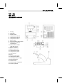
Esquema del aparato
1
2
3
4.
5
6
7
8
9
10
11
12
13
14
15
16
17
18
19
20
21
22
Pantalla
Tecla UP (subir)
Tecla DOWN (bajar)
Tecla de la temperatura III
Tecla de la temperatura II
Tecla de la temperatura I
Interruptor principal
Conector hembra para el
equipotencial
Clavija de conexión para el
soldador
Interfaz USB, B-Mini
(WD 1M opcional)
Conector principal
Fusible de red
Indicación de temperatura
Símbolo de temperatura
Función de tiempo
Bloqueo
Control óptico de regulación
Teclas de la temperatura
Indicador de temperatura fijo
Funciones especiales
Soporte cónico
Soporte para las puntas de
soldar
23 Elemento de limpieza
WD 1 (M) / WD 1000
3-18
4 Descripción del aparato ........................................................... 5
5 Puesta en marcha del aparato ................................................. 7
6 Manejo del aparato .................................................................. 8
7 Funciones especiales .............................................................. 10
8 Restaurar los ajustes de fábrica ............................................... 17
13 Garantía................................................................................... 18
Información breve sobre este manual
Le agradecemos mucho la compra del equipo Weller WD 1 (M) /
WD 1000 y la confianza depositada en nosotros. La fabricación de
este aparato está sometida a los más rigurosos controles de calidad
para garantizar un perfecto funcionamiento del mismo.
Este manual de uso contiene información importante para poder
poner en marcha y manejar de forma segura y adecuada la estación
de soldar WD 1 (M) / WD 1000, así como para realizar tareas de
mantenimiento e incluso reparar pequeñas averías.
Antes de comenzar a trabajar con la estación de soldar
WD 1 (M) / WD 1000 lea atentamente todas las siguientes
instrucciones de seguridad.
Mantenga este manual de uso en un lugar al que puedan
acceder todos los usuarios del aparato.
1.2
Otros documentos aplicables
Manual de uso de la estación de soldar WD 1 (M) / WD 1000
Folleto adjunto a estas instrucciones con las normas de seguridad
ES
SV
EE
SL
Directivas aplicables
LV
1.1
La estación de soldar Weller WD 1 (M) / WD 1000 regulada
mediante un microprocesador cumple los requisitos de la
Declaración de conformidad CE con las Directivas 2004/108/CE,
2006/95/CE y 2011/65/EU (RoHS).
LT
1
DK
12 Eliminación de residuos ........................................................... 18
FI
11 Accesorios ............................................................................... 18
GR
10 Mensajes de error y su reparación ........................................... 17
NL
estación
TR
la
CZ
de
PL
mantenimiento
HU
y
WD 1 (M) / WD 1000 ................................................................ 17
SK
9 Conservación
IT
3 Piezas suministradas ............................................................... 4
ES
2 Por su propia seguridad ........................................................... 4
PT
1 Información breve sobre este manual ...................................... 3
EN
DE
Índice
4-18
WD 1 (M) / WD 1000
2 Por su propia seguridad
La estación de soldar WD 1 (M) / WD 1000 ha sido fabricada según
los últimos avances tecnológicos y de conformidad con la normativa
de seguridad técnica. No obstante, existe riesgo de que se
produzcan daños personales o materiales si no se respetan las
instrucciones de seguridad que figuran en el folleto de seguridad
adjunto, así como las advertencias de este manual de uso. Entregue
la estación de soldar WD 1 (M) / WD 1000 a terceros siempre junto
con el manual de uso.
2.1
Utilización reglamentaria
Utilice la estación de soldar WD 1 (M) / WD 1000 exclusivamente
para la finalidad indicada, es decir soldar y desoldar, bajo las
condiciones indicadas en el manual de instrucciones. La utilización
reglamentaria de la estación de soldar WD 1 (M) / WD 1000 implica
también que
siga las instrucciones de este manual,
siga las instrucciones de todos los documentos que acompañan al
aparato,
respete la normativa nacional vigente para la prevención de
accidentes laborales.
El fabricante no asume ninguna responsabilidad en caso de
realizarse modificaciones por cuenta propia en el aparato.
3 Piezas suministradas
WD 1
WD 1000 WD 1M
Unidad de control
Cable de
alimentación
Conector
Soldador
Soporte de
seguridad
Instrucciones de
funcionamiento
Folleto Normas de
seguridad
4.1
Soporte de seguridad
El soporte cónico (21) para el soldador se puede ajustar en 4
posiciones diferentes sin necesidad de utilizar herramientas para
poder colocarlo en la posición más ergonómica. En la parte trasera
(22) se pueden guardar las puntas de soldar. La placa de fondo del
soporte incorpora una elemento de limpieza (23) para poder limpiar
la punta de soldar.
EN
ES
IT
ES
PT
NL
SV
DK
FI
GR
TR
CZ
PL
HU
La estación de soldar Weller WD 1 (M) / WD 1000 le ofrece las
siguientes funciones adicionales:
Detección automática de la herramienta y activación de los
correspondientes parámetros de regulación
Regulación digital de temperatura
Posibilidad de introducir valores de offset
Descenso de temperatura programable (Setback)
Función standby y de bloqueo
Versión antiestática del aparato según la seguridad ESD
Diferentes posibilidades de compensación de potencial en el
aparato (configuración estándar con toma de tierra directa)
Función de calibración específica del cliente
SK
Puede conectar cualquier soldador (excepto de Microtools) de hasta
80 vatios a la estación WD 1. El margen de temperatura es de
50 °C – 450 °C (150 °F – 850 °F) y para el soldador. La WD 1M es
multifuncional y se le pueden conectar todos los soldadores de
hasta 150 vatios y Mircotools (WMRP & WMRT). El margen de
temperatura es de 50 °C – 450 °C (150 °F – 850 °F). El valor de
referencia y real se muestra de forma digital. Las tres teclas de
temperatura sirven para la selección directa de las temperaturas
fijas. Cuando se alcanza la temperatura establecida el control óptico
de regulación (símbolo "" en la pantalla) comienza a parpadear.
SL
En combinación con la técnica de sensores y transmisión térmica de
alta calidad en la herramienta de soldar, la electrotecnia digital de
regulación garantiza un comportamiento de regulación de la
temperatura muy preciso en la punta de soldar. La rápida captación
de los valores de medición proporciona la máxima precisión de
temperatura y un comportamiento térmico dinámico optimizado bajo
carga.
EE
La Weller WD 1 (M) / WD 1000 es una estación de soldar muy
versátil para trabajos de reparación profesionales de componentes
electrónicos de última generación en la técnica industrial de
producción, así como en el sector de reparación y laboratorio.
LV
4 Descripción del aparato
DE
5-18
LT
WD 1 (M) / WD 1000
6-18
WD 1 (M) / WD 1000
4.2
Datos técnicos WD 1 (M) / WD 1000
Dimensiones
L x An x Al (mm): 134 x 108 x 147
L x B x H (pulgadas): 5,27 x 4,27 x 5,77
Peso
aproximadamente 3,4 kg
Tensión de red
230 V, 50/60 Hz
120 V, 60 Hz
100 V, 50/60 Hz
Consumo de potencia
95 W
Clase de protección
I y III, caja antiestática
Fusible (12):
T 500 mA (230 V, 50 / 60 Hz)
T 1,0 A (120 V, 60 Hz)
T 1,25 A (100 V, 50 / 60 Hz)
Sólo WD 1 / WD 1000
Fusible (12)
Sólo WD 1 M/ WD 1000M
T 800 mA (230 V, 50 / 60 Hz)
T 1,6 A (120 V, 60 Hz)
T 1,6 A (100 V, 50 Hz)
Regulador de temperatura
50 °C – 450 °C (150 °F – 842 °F)
Precisión de la temperatura
± 9 °C (± 17 °F)
Estabilidad térmica
± 5 °C (± 9 °F)
Resistencia de escape punta Corresponde a IPC-J-001D
de soldar (tip to ground)
Tensión de escape punta de Corresponde a IPC-J-001D
soldar (tip to ground)
Equipotencial
Conector hembra de 3,5 mm en la parte
inferior del aparato (8).
Equipotencial
Gracias a las diferentes posibilidades de conexión del conector
hembra de 3,5 mm (8) hay 4 variantes posibles:
Puesta a tierra dura: sin clavija (estado de entrega).
Compensación de potencial: con clavija, línea de compensación
en el contacto central.
Sin potencial: con clavija
Puesta a tierra blanda: con clavija y resistencia soldada. Puesta a
tierra a través de la resistencia seleccionada
Interfaz USB
Las unidades de control WD 1M y WD 1000 están equipadas con
una interfaz Mini USB (10). Para poder utilizar la interfaz USB, usted
dispone de un software de Weller en el
http://www.weller.de/en/Weller---Download-Center--SoftwareUpdates.html con el cual
puede efectuar una actualización de software (“Firmware
Updater“) en su control y
manejar el control a distancia, así como representar en forma de
gráficos, guardar e imprimir las curvas de temperatura
gráficamente (“Monitorsoftware“).
5.
6.
Después de conectar el aparato, el microprocesador realiza un
autochequeo, durante el cual todos los indicadores están
brevemente en servicio. Después se indica brevemente la
temperatura ajustada (valor de referencia) y el tipo de grados de la
temperatura (°C / °F). Después el sistema electrónico indica
automáticamente la temperatura real. Aparece el símbolo " "(17) en
la pantalla (1) como control óptico de regulación:
Cuando la luz permanece encendida constantemente significa
que el sistema se está calentando.
Si el LED parpadea significa que se ha alcanzado la temperatura
ajustada previamente.
Nota
Para saber qué utensilios se pueden conectar a la estación
WD 1 (M) / WD 1000 consulte la lista de accesorios de la
página 18.
EN
ES
IT
ES
PT
NL
SV
DK
FI
GR
3.
4.
Introducir el conector macho del soldador en el conector hembra
(9) de la unidad de control y fijar su posición girándolo
ligeramente hacia la derecha.
Depositar el soldador en el soporte de seguridad.
Comprobar si la tensión de la red coincide con la de la placa de
datos técnicos y si el interruptor principal (7) está desconectado.
Conectar la unidad de control a la red (11).
Encender el aparato con el interruptor principal (7).
TR
1. Desembalar el aparato cuidadosamente.
2. Conectar las herramientas de soldar como sigue:
CZ
Siempre y cuando no utilice el soldador colóquelo en el
soporte de seguridad.
PL
Lea detenidamente todas las normas de seguridad adjuntas,
las normas de seguridad del manual de uso, así como las
instrucciones de su unidad de control antes de ponerla en
funcionamiento y siga siempre las normas de precaución.
HU
Si se conecta inadecuadamente la unidad de control existe
peligro de provocar daños personales y materiales. Durante el
funcionamiento de la unidad de control existe peligro de sufrir
quemaduras con el soldador.
SK
¡ADVERTENCIA! Peligro de descarga eléctrica y de sufrir quemaduras
SL
5 Puesta en marcha del aparato
EE
Las unidades de control WD 1 y WD 1M se pueden equipar en
cualquier momento con una interfaz USB (consulte la lista de
accesorios de la página 18.)
LV
Nota
DE
7-18
LT
WD 1 (M) / WD 1000
8-18
WD 1 (M) / WD 1000
6 Manejo del aparato
6.1
Ajuste de la temperatura
Ajuste individual de la temperatura
1. Conectar el aparato con el interruptor principal (7).
La pantalla indica la temperatura real.
2. Pulsar la tecla UP o DOWN.
La pantalla muestra al valor de referencia ajustado. El símbolo
de temperatura (14) parpadea.
3. Pulsar la tecla UP o DOWN para ajustar la temperatura teórica
deseada:
- Una breve pulsación supone un cambio de un grado del valor
de referencia.
- Una pulsación permanente supone un cambio rápido del valor
de referencia.
Aproximadamente 2 segundos después de soltar las teclas de
ajuste vuelve a aparecer en la pantalla el valor real del canal
seleccionado.
4. Pulsar la tecla UP y DOWN al mismo tiempo.
Si el canal se encuentra ahora inactivo, aparece en la pantalla la
indicación “OFF“.
Si ahora el canal está activo, aparece en la pantalla la
temperatura actual de valor real.
Los datos grabados no se borran al desconectar el canal.
Seleccionar la temperatura con la teclas I, II y III
Se puede ajustar el valor de referencia de la temperatura mediante
la selección de tres valores de temperatura preajustados
(temperaturas fijas).
Ajustes de fábrica:
I = 150 °C (300 °F), II = 350 °C (662 °F), III = 380 °C (716 °F)
Pulsar la tecla de la temperatura deseada I, II o III .
El valor de referencia seleccionado aparecerá indicado en la
pantalla durante aprox. 2 seg. El símbolo de temperatura
parpadeará durante la indicación de la temperatura de
referencia.
Después la pantalla indicará de nuevo automáticamente la
temperatura real.
Ajuste de la temperatura de las teclas I, II y III
1. Pulsar la tecla de la temperatura deseada I, II o III .
2. Ajustar el valor de referencia de temperatura con la tecla UP o
DOWN.
3. Mantener pulsada la tecla de la temperatura deseada I, II o III
durante tres segundos.
Nota
Las unidades de control están ajustadas para funcionar con puntas
de soldar de tamaño mediano. Pueden surgir diferencias debido al
cambio de punta o al utilizar puntas con una forma diferente.
EN
ES
IT
ES
PT
NL
SV
DK
FI
GR
TR
Al calentar por primera vez la punta de soltar seleccionada
aplicarle un poco de estaño. De esta forma se eliminan posibles
restos de óxido o impurezas que pueden aparecer durante su
almacenaje.
Para realizar descansos mientras suelda o al colocar el soldador
en el soporte es imprescindible procurar que la punta de soldar
esté bien estañada.
No utilizar fundentes agresivos.
Asegurarse de que las puntas de soltar estén siempre colocadas
correctamente.
Ajustar la temperatura más baja posible
Seleccionar la punta de soldar más grande posible para la
aplicación deseada, por regla general: aprox. tan grande como el
punto de soldadura
Procurar que el calor se transmita ampliamente entre la punta de
soldar y el punto de soldadura estañando bien la punta de soldar.
En caso de pausas prolongadas desconectar el equipo y utilizar la
función de reducción de la temperatura de la estación Weller.
Humedecer la punta de soldar antes de colocar el soldador en el
soporte.
Aplicar el estaño directamente en el punto de soldadura para que
se funda y no en la punta de soldar.
Cambiar las puntas de soldar con las herramientas apropiadas.
No someter la punta de soldar a esfuerzos mecánicos.
CZ
Manipulación de las puntas de soldar
PL
Realice los trabajos de soldadura según el manual de
instrucciones de la herramienta de soldar conectada.
HU
Soldar y desoldar
SK
6.2
SL
La asignación de una tecla de temperatura con una temperatura
“Setback“ inferior brinda la posibilidad de realizar un descenso de
temperatura manual en caso de no usar el soldador.
EE
Nota
LV
Mientras tanto parpadea la indicación de temperatura para el
correspondiente valor de temperatura. Al cabo de 3 segundos se
guarda el valor ajustado.
4. Volver a soltar la tecla de temperatura.
DE
9-18
LT
WD 1 (M) / WD 1000
10-18
WD 1 (M) / WD 1000
7 Funciones especiales
2s➾
Menú 1
4s➾
Menú 2
1x ➾
ON/OFF
Las funciones especiales se dividen en 2 niveles de menú:
Menú 1 con los posibles ajustes de
temperatura STANDBY, desconexión de la temperatura (función
de reducción de la temperatura (SETBACK)), tiempo de
desconexión automático (Auto-OFF), temperatura Offset , función
WINDOW, unidad de temperatura y función de bloqueo.
Menú 2 con los ajuste posibles del código ID, la función de
calibración (FCC).
7.1
Seleccionar las funciones especiales del
menú 1
Funciones
especiales
Navegación
STANDBY
I
SETBACK
AUTO OFF
II
OFFSET
WINDOW
°C / °F
EXIT
III
1. Mantener pulsadas al mismo tiempo las teclas UP y DOWN.
Al cabo de 2 s aparece la indicación “– 1 –“ en la pantalla.
2. Soltar las teclas.
La selección de las funciones especiales del menú 1 está
activada.
Ahora se pueden efectuar los ajustes.
- Seleccionar los puntos del menú con las teclas I, II.
- Volver a salir del menú con la tecla III (EXIT).
Restaurar los ajustes de fábrica de las funciones especiales
1. Pulsar y mantener pulsada la tecla III .
2. A continuación se deben pulsar simultáneamente las teclas UP y
DOWN.
En la pantalla aparece “FSE“.
A partir de ahora la estación de soldar está ajustada con la
configuración de fábrica.
Ajustar la temperatura standby
Después de una desconexión de temperatura se ajusta
automáticamente la temperatura standby. La temperatura de valor
real se muestra parpadeando. En la pantalla aparecerá "STANDBY"
(100 °C – 300 °C / 200 °F– 600 °F).
En los trabajos de soldadura que requieran poca temperatura se
puede ver mermada la fiabilidad de la función Setback.
EN
ES
IT
ES
PT
NL
SV
PL
HU
SK
SL
Son posibles los siguientes ajustes de tiempo AUTO-OFF:
“0 min“: la función AUTO-OFF está desactivada.
“1-999 min“: tiempo AUTO-OFF, ajustable individualmente.
1. Seleccionar el punto de menú OFF en el menú 1.
2. Ajustar el valor de referencia del tiempo AUTO-OFF con la tecla
UP o DOWN.
3. Mediante la tecla I (atrás) o II (siguiente) es posible avanzar o
retroceder en el menú.
EE
La desconexión de temperatura se realiza independientemente de la
función de Setback ajustada. La temperatura de valor real se
muestra parpadeando y sirve como indicación del calor residual. En
al pantalla aparece “OFF“. Por debajo del valor de 50 °C (150 °F)
aparece una raya parpadeando en la pantalla.
LV
Cuando no se utiliza la herramienta de soldar, se desconecta el
calentador de ésta después de que haya transcurrido el tiempo
AUTO-OFF.
CZ
Ajustar el tiempo de desconexión automática (AUTO-OFF)
LT
Nota
DK
Son posibles los siguientes ajustes de Setback:
“0 min“: Setback OFF (ajuste de fábrica)
“ON“: Setback ON (con el soporte de seguridad la temperatura del
soldador se reduce a la temperatura Standby inmediatamente
después de colocar el soldador en el soporte).
“1-99 min“: Setback ON (tiempo de Setback ajustable
individualmente)
1. Seleccionar el punto de menú SETBACK en el menú 1.
2. Ajustar el valor de Setback con la tecla UP o DOWN.
3. Mediante la tecla I (atrás) o II (siguiente) es posible avanzar o
retroceder en el menú.
FI
Ajustar la desconexión de temperatura (SETBACK)
Cuando no se utiliza la herramienta de soldar, la temperatura se
reduce hasta alcanzar la temperatura Standby después de que haya
transcurrido el tiempo de Setback ajustado. El estado de Setback se
muestra por medio de la indicación de valor real parpadeando y en
la pantalla aparece “STANDBY“. Este estado de Setback finaliza al
pulsar la tecla UP o DOWN. En función de la herramienta, el
interruptor integrado en el mango o el soporte de seguridad
desactiva el estado de Setback.
GR
1. Seleccionar el punto de menú STANDBY en el menú 1.
2. Ajustar el valor de referencia de la temperatura standby con la
tecla UP o DOWN.
3. Mediante la tecla I (atrás) o II (siguiente) es posible avanzar o
retroceder en el menú.
DE
11-18
TR
WD 1 (M) / WD 1000
12-18
WD 1 (M) / WD 1000
Comportamiento térmico con diferentes ajustes de las funciones
SETBACK y AUTO OFF
Ajustes
Comportamiento térmico sin soporte de seguridad
SETBACK
OFF Time
Time [1-99 min] [1-999 min]
0
ON
0
ON
Time
Time
0
La herramienta de soldar mantiene la temperatura de soldadura
ajustada.
Time
Cuando no se utiliza la herramienta de soldar 1) ésta se desconecta
después de que haya transcurrido del tiempo OFF.
0
Cuando no se utiliza el soldador 1)se reduce la temperatura del
soldador a la temperatura STANDBY2) después de que haya
transcurrido el tiempo de SETBACK.
Time
Cuando no se utiliza la herramienta de soldar 1) se reduce la
temperatura del soldador a la temperatura STANDBY 2) después de
que haya transcurrido el tiempo de SETBACK y se desconecta
después de que haya transcurrido el tiempo OFF.
Comportamiento térmico con soporte de seguridad
0
0
La herramienta de soldar se desconecta en el soporte 3).
ON
0
En el soporte 3) se reduce la temperatura de la herramienta de
soldar hasta alcanzar la temperatura STANDBY 2).
0
Time
En el soporte 3) se desconecta la herramienta de soldar después de
que haya transcurrido el tiempo OFF.
ON
Time
En el soporte 3) la temperatura de la herramienta de soldar se
reduce hasta alcanzar la temperatura STANDBY 2) y se desconecta
después de que haya transcurrido el tiempo OFF.
Time
0
En el soporte 3) la temperatura de la herramienta de soldar se
reduce hasta alcanzar la temperatura STANDBY2) después de que
haya transcurrido el tiempo de SETBACK.
Time
En el soporte 3)la temperatura de la herramienta de soldar se
reduce hasta alcanzar la temperatura STANDBY 2) después de que
haya transcurrido el tiempo de SETBACK y se desconecta después
de que haya transcurrido el tiempo OFF.
Time
1)
Si no se utiliza = no pulsar las teclas UP/DOWN; sin descenso de la temperatura > 3 °C.
2)
La temperatura STANDBY debe ser inferior a la temperatura teórica ajustada ya, de lo contrario, la
función de SETBACK está inactiva.
3)
Si hay conectado un soporte de seguridad, la herramienta de soldar mantendrá la temperatura de
referencia ajustada cuando se encuentra fuera del soporte.
La función del soporte se activa tras colocar la herramienta de soldar por primera vez en el soporte
Nota
Reset del modo STANDBY y OFF:
Sin soporte de seguridad pulsando la tecla UP o DOWN.
Con soporte de seguridad al retirar la herramienta de soldar del
soporte.
Activar/desactivar la función de bloqueo
Una vez activado el bloqueo tan sólo se pueden manejar las teclas
de la temperatura I, II y III . No es posible cambiar ninguno de los
demás ajustes hasta que se realice el desbloqueo.
Bloqueo de la estación de soldar:
1. Seleccionar el punto de menú LOCK en el menú 1.
En la pantalla se muestra “OFF“. El símbolo de la llave parpadea.
Nota
Si se pulsa una de las teclas I o II mientras se muestra “OFF“, se
sale del punto de menú sin haber guardado el código de bloqueo.
2. Ajustar el código de bloqueo de tres dígitos con la tecla UP o
DOWN.
3. Pulsar la tecla III durante 5 seg.
Se guarda el código. Se muestra el símbolo de la llave. Ahora la
estación está bloqueada. La indicación cambia al menú principal.
EN
ES
IT
ES
PT
NL
SV
DK
FI
GR
Cambiar la unidad de temperatura de °C a °F o viceversa.
1. Seleccionar el punto de menú °C / °F en el menú 1.
2. Ajustar la unidad de temperatura con la tecla UP o DOWN.
3. Mediante la tecla I (atrás) o II (siguiente) es posible avanzar o
retroceder en el menú.
TR
Cambiar la unidad de temperatura
CZ
1. Seleccionar el punto de menú WINDOW en el menú 1.
2. Ajustar el valor de temperatura WINDOW con la tecla UP o
DOWN.
3. Mediante la tecla I (atrás) o II (siguiente) es posible avanzar o
retroceder en el menú.
PL
Para poder utilizar la función WINDOW es necesario que la
estación de soldar se encuentre bloqueada (véase
“Activación/desactivación de la función de bloqueo“).
HU
Nota
SK
Partiendo de una temperatura ajustada y bloqueada es posible
ajustar un margen de temperatura de aproximadamente ± 99 °C
(± 180 °F) con la ayuda de la función WINDOW.
SL
Ajustar la función de ventana
EE
La temperatura real de la cabeza del soldador se puede adaptar
mediante la entrada de un offset de temperatura de
aproximadamente ± 40 °C (± 72 °F).
1. Seleccionar el punto de menú OFFSET en el menú 1.
2. Ajustar el valor de temperatura OFFSET automático con la tecla
UP o DOWN.
3. Mediante la tecla I (atrás) o II (siguiente) es posible avanzar o
retroceder en el menú.
LV
Ajustar el offset de temperatura
DE
13-18
LT
WD 1 (M) / WD 1000
14-18
WD 1 (M) / WD 1000
Desbloqueo de la estación de soldar:
1. Seleccionar el punto de menú LOCK en el menú 1.
En la pantalla se muestra “ON“. Se muestra el símbolo de la
llave.
2. Introducir el código de bloqueo de tres dígitos con la tecla UP o
DOWN.
3. Pulsar la tecla III.
La estación está ahora desbloqueada. La indicación cambia al
menú principal.
Nota
El desbloqueo de la estación de soldar también es posible
mediante la lista de descodificación o el conector Reset.
7.2
Seleccionar las funciones especiales del
menú 2
Funciones especiales
ID
FCC
AUTO CHANNEL
Navegación
I
II
III
EXIT
HI / LO CONTROL
1. Seleccionar el canal deseado I, II o III para la entrada de las
funciones especiales.
2. Mantener pulsadas al mismo tiempo las teclas UP y DOWN.
Al cabo de 4 s aparece la indicación “– 2 –“ en la pantalla.
3. Soltar las teclas.
La selección de las funciones especiales del menú 2 está
activada.
Ahora se pueden efectuar los ajustes.
- Seleccionar los puntos del menú con las teclas I y II.
- Volver a salir del menú con la tecla III (EXIT).
Ajustar la identificación de la estación (código ID)
Si se utiliza la interfaz USB opcional, se pueden activar y controlar a
distancia varias estaciones de soldar WD 1 (M) / WD 1000 con
todas sus funciones. Cada estación necesita a tal fin una
identificación de la estación (código ID) para que pueda ser
identificada inequívocamente.
1. Seleccionar el punto de menú REMOTE ID en el menú 2.
2. Introducir una ID con la tecla UP o DOWN
(valores posibles 0 - 999).
3. Mediante la tecla I (atrás) o II (siguiente) es posible avanzar o
retroceder en el menú.
Nota
Pulsar la tecla III para salir del punto de menú sin cambios (EXIT).
Ejemplo:
Pantalla 100 °C, aparato de medición externo 98 °C: ajuste 2
Pantalla 100 °C, aparato de medición externo 102 °C: ajuste 2
Nota
Pulsar la tecla III para salir del punto de menú sin cambios (EXIT).
6. Pulsar la tecla II (Set) para confirmar el valor.
Ahora se ha restaurado la desviación de temperatura a cero. La
calibración ha finalizado ahora con 100 °C / 212 °F.
7. Salir del menú 2 pulsando la tecla III.
EN
ES
IT
ES
PT
NL
SV
DK
FI
GR
TR
CZ
PL
1. Introducir la sonda de temperatura (0,5 mm) del aparato de
medición de temperatura externo en la punta de medición de
temperatura.
2. Seleccionar el punto de menú FCC en el menú 2.
3. Pulsar la tecla DOWN.
Se selecciona el punto de calibración 100 °C / 212 °F.
Ahora se calienta la punta de soldar hasta alcanzar
100 °C / 212 °F.
El control de regulación parpadea mientras la temperatura esté
constante.
4. Comparar las temperaturas indicadas del aparato de medición
con la indicación de la pantalla.
5. Con la tecla UP o DOWN se puede ajustar la diferencia entre el
valor mostrado en el aparato de medición externo y el valor de la
estación de soldar mostrado en la estación.
Máximo ajuste de temperatura posible ± 40 °C (± 72 °F).
HU
Cambiar la calibración con 100 °C / 212 °F
SK
No tocar la herramienta de soldar cuando esté caliente y no
colocar objetos inflamables cerca de la misma.
SL
Los utensilios de soldar se calientan durante el proceso de
calibrado. En caso de contacto existe peligro de sufrir
quemaduras.
EE
¡ADVERTENCIA! Existe peligro de sufrir quemaduras
LV
Manejo de la función de calibración (Factory Calibration Check)
La función FCC permite comprobar la precisión de temperatura de la
estación de soldar y compensar las posibles desviaciones. A tal fin
es necesario medir la temperatura de la cabeza del soldador con un
aparato de medición de temperatura externo y una punta de
medición de temperatura asignada a la herramienta de soldar. Antes
de realizar la calibración se debe seleccionar el correspondiente
canal.
DE
15-18
LT
WD 1 (M) / WD 1000
16-18
WD 1 (M) / WD 1000
Cambiar la calibración con 450 °C / 842 °F
1. Introducir la sonda de temperatura (0,5 mm) del aparato de
medición de temperatura externo en la punta de medición de
temperatura.
2. Seleccionar el punto de menú FCC en el menú 2.
3. Pulsar la tecla UP.
Se selecciona el punto de calibración 450 °C / 842 °F.
Ahora se calienta la punta de soldar hasta alcanzar
450 °C / 842 °F.
El control de regulación parpadea mientras la temperatura esté
constante.
4. Comparar las temperaturas indicadas del aparato de medición
con la indicación de la pantalla.
5. Con la tecla UP o DOWN se puede ajustar la diferencia entre el
valor mostrado en el aparato de medición externo y el valor de la
estación de soldar mostrado en la estación.
Máximo ajuste de temperatura posible ± 40 °C (± 72 °F).
Ejemplo:
Pantalla 450 °C, aparato de medición externo 448 °C: ajuste 2
Pantalla 450 °C, aparato de medición externo 452 °C: ajuste 2
Nota
Pulsar la tecla III para salir del punto de menú sin cambios (EXIT).
6. Pulsar la tecla II (Set) para confirmar el valor.
Ahora se ha restaurado la desviación de temperatura a cero. La
calibración ha finalizado ahora con 450 °C / 842 °F.
7. Salir del menú 2 pulsando la tecla III.
Restaurar los ajustes de fábrica de la calibración
1. Seleccionar el punto de menú FCC en el menú 2.
2. Mantener pulsada la tecla III.
3. A continuación se deben pulsar simultáneamente las teclas UP y
DOWN.
En la pantalla aparece “FSE“ (Factory Setting Enabled).
A partir de ahora la estación de soldar está calibrada con la
configuración de fábrica.
4. Mediante la tecla I (atrás) o II (siguiente) es posible avanzar o
retroceder en el menú.
Ajuste del control de regulación de WP 120
Mediante la función HI / LO CONTROL se puede ajustar el control
de regulación de WP 120 (ajustado de fábrica a HI):
1. Seleccionar el punto de menú HI / LO del menú 2.
2. Ajustar el estado con la tecla UP (HI) o DOWN (LO).
Restablecimiento de las funciones especiales
Esta función se describe en el apartado 7.1 "Selección de funzione
especiales menú 1“, "Restablecimiento de los ajustes de fábrica
para las funciones especiales“ de la página 10.
EN
8 Restaurar los ajustes de fábrica
DE
17-18
ES
WD 1 (M) / WD 1000
No hay función de pantalla (la No hay tensión de red
pantalla está apagada)
disponible
Conectar el interruptor principal
Comprobar la tensión de red
Comprobar el fusible del aparato
ES
PT
NL
SV
DK
FI
Volver a introducir la punta de
soldar
Cambiar la punta de soldar
defectuosa
GR
La punta de soldar de la
microherramienta no está
introducida correctamente o
está defectuosa
TR
Indicación "tip"
CZ
Comprobar la conexión de la
herramienta al aparato
Comprobar la herramienta
conectada
PL
Indicación “- - -“
HU
Remedio
No se ha detectado la
herramienta
Herramienta defectuosa
SK
Causa posible
SL
Mensaje/Síntoma
EE
10 Mensajes de error y su reparación
LV
La zona de transición entre la resistencia / sensor y la punta de
soldar no debe estar sucia, ni presentar restos de otros materiales o
daños puesto que de lo contrario alteraría la precisión del regulador
de temperatura.
LT
9 Conservación y mantenimiento de la
estación WD 1 (M) / WD 1000
IT
Restaurar los ajustes de fábrica de la calibración
Esta función se describe en el apartado 7.2 "Selección de funzione
especiales menú 2“, "Restaurar los ajustes de fábrica de la
calibración“ de la página 14.
18-18
WD 1 (M) / WD 1000
11 Accesorios
T005 13 841 99
T005 15 125 99
T005 15 161 99
T005 15 162 99
T005 27 028 99
T005 27 040 99
T005 29 178 99
T005 29 179 99
T005 29 181 99
T005 29 188 99
T005 33 133 99
T005 87 597 28
T005 87 597 27
T005 31 185 99
Lana de acero para WDC 2
WDC 2 Accesorio para limpieza en seco
WDH 10T Soporte de seguridad WSP 80/WP 80
WDH 20T Soporte de seguridad para WMP
Placa precalefactora WHP 80
WSB 80 baño de soldadura, 80 Vatios
Kit de accesorios para soldador WSP 80
Kit de accesorios para soldador WMP
WP 80 kit de soldador, 80 Vatios
Kit de accesorios para desoldar LR 82
Kit de accesorios para desoldador WTA 50
Conector reset °C
Conector reset °F
USB módulo complementario
Sólo para WD 1M
T005 13 173 99
Kit de accesorios para desoldar WMRT
T005 27 042 99
WSB 150 baño de soldadura, 150 Vatios
T005 29 189 99
WSP 150 kit de soldador, 150 Vatios
T005 15 152 99
WDH 30 bandeja para WSP 150
T005 29 190 99
Kit de accesorios para soldar WMRP
T005 29 193 99
WP 120 soldador, 120 Vatios
T005 15 121 99
WDH 10 bandeja para
Consultar el resto de los accesorios en los manuales de uso de los
diferentes kits de accesorios para soldador.
12 Eliminación de residuos
Elimine los componentes y filtros cambiados en el aparato, así como
aparatos en desuso, siguiendo la normativa vigente en su país.
13 Garantía
Los derechos de reclamación por defectos del comprador prescriben
un año después de la compra. Sólo válido para los derechos del
comprador según el art. §§ 478, 479 BGB (código civil alemán).
Únicamente nos responsabilizamos de los derechos de garantía
cuando la garantía de compra y vida útil del aparato haya sido
entregada por nosotros por escrito y utilizando el término "Garantía".
¡Reservado el derecho a realizar modificaciones técnicas!
Encontrará los manuales de instrucciones actualizados en
www.weller-tools.com.
LT
LV
EE
SL
SK
HU
PL
CZ
TR
GR
R9
R8
FI
DK
SV
NL
R16
PT
ES
IT
FR
EN
DE
WD 1 / WD 1000 – Circuit Diagram
C2
WD 1 / WD 1000 – Exploded Drawing
LT
LV
EE
SL
SK
HU
PL
CZ
TR
GR
FI
DK
SV
NL
PT
ES
IT
FR
EN
DE
WD 1M / WD 1000 – Circuit Diagram
WD 1M / WD 1000 – Exploded Drawing
T005 56 869 15
T005 56 869 14
/ 07.2015
/ 07.2014
GERMANY
Weller Tools GmbH
Carl-Benz-Str. 2
74354 Besigheim
Phone: +49 (0) 7143 580-0
Fax: +49 (0) 7143 580-108
SWEDEN
Apex Tool Group AB
Fabriksgatan 4
531 30 Lidköping
Phone: +46 (0) 510 77 71 720
AUSTRALIA
Apex Tools
P.O. Box 366, 519 Nurigong Street
Albury, N. S. W. 2640
Phone: +61 (2) 6058-0300
Fax: +61 (2) 6021-7403
ITALY
Apex Tool S.r.I.
Viale Europa 80
20090 Cusago (MI)
Phone: +39 (02) 9033101
Fax: +39 (02) 90394231
SWITZERLAND
Apex Tool Switzerland Sàrl
Crêt-St-Tombet 15
2022 Bevaix
Phone: +41 (0) 24 426 12 06
Fax:
+41 (0) 24 425 09 77
INDIA
Apex Power Tools India Pvt. Ltd.
Regus business centre
Level 2, Elegance, Room no. 214
Mathura Road, Jasola
New Delhi - 110025
FRANCE
Apex Tool Group S.N.C
25 Av Maurice Chevalier
77832 Ozoir-la-Ferrière Cedex
Phone: +33 (0) 1.64.43.22.00
Fax: +33 (0) 1.64.43.21.62
USA
Apex Tool Group, LLC
14600 York Rd. Suite A
Sparks, MD 21152
Phone: +1 (800) 688-8949
Fax: +1 (800) 234-0472
CHINA
Apex Tool Group
A-8 Building, No. 38 Dongsheng Road,
Heqing Industrial Park, Pudong
Shanghai 201201
Phone: +86 (21) 60 88 02 88
Fax: +86 (21) 60 88 02 89
GREAT BRITAIN
Apex Tool Group
(UK Operations) Ltd
4th Floor Pennine House
Washington, Tyne & Wear
NE37 1LY
Phone: +44 (0) 191 419 7700
CANADA
Apex Tools - Canada
5925 McLaughlin Rd. Mississauga
Ontario L5R 1B8
Phone: +1 (905) 455 5200
Fax: +1 (905) 387-2640
SOUTH EAST ASIA
Apex Power Tools India Pvt. Ltd.
Gala No. 1, Plot No. 5
S. No. 234, 235, 245
India land Global Industrial Park
(Next to Tata Johnson Control)
Taluka-Mulsi, Phase-I
Hinjawadi Pune (411057)
Maharashtra, India
[email protected]
Fax:
+44 (0) 191 417 9421
www.weller-tools.com
© 2015, Apex Tool Group, LLC.
Weller® is a registered Trademark and registered Design of Apex Tool Group, LLC.