1
Original Instructions
Original-Betriebsanleitung
Istruzioni originali
Instrucciones originales
Instruções Originais
Consignes originales
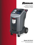
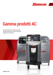
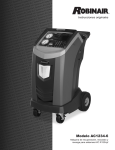
Model AC1234-3
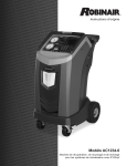
Model AC1234-3P
Recover, Recycle, Recharge Machine
for R1234yf A/C Systems
Description: Recover, recycle, and recharge machine for use
with R1234yf equipped air conditioning systems.
PRODUCT INFORMATION
Record the serial number and year of manufacture of this unit for future reference. Refer to the
product identification label on the unit for information.
AC1234-3
Serial Number:________________________________Year of Manufacture:_____________
DISCLAIMER: Information, illustrations, and specifications contained in this manual are based on the latest information available
at the time of publication. The right is reserved to make changes at any time without obligation to notify any person or organization
of such revisions or changes. Further, ROBINAIR shall not be liable for errors contained herein or for incidental or consequential
damages (including lost profits) in connection with the furnishing, performance, or use of this material. If necessary, obtain additional
health and safety information from the appropriate government agencies, and the vehicle, refrigerant, and lubricant manufacturers.
Table of Contents
Safety Precautions . . . . . . . . . . . . . . . . . . . . . . . . . . . . . . . . . . . . . . . . . . . . . . . . . . . . . . . . . . . . 2
Introduction
Technical Specifications . . . . . . . . . . . . . . . . . . . . . . . . . . . . . . . . . . . . . . . . . . . . . . . . . . .
Features of the AC1234-3(P) . . . . . . . . . . . . . . . . . . . . . . . . . . . . . . . . . . . . . . . . . . . . . . .
Control Panel Functions . . . . . . . . . . . . . . . . . . . . . . . . . . . . . . . . . . . . . . . . . . . . . . . . . . .
Setup Menu Functions . . . . . . . . . . . . . . . . . . . . . . . . . . . . . . . . . . . . . . . . . . . . . . . . . . . .
5
6
7
8
Initial Setup
Unpack the Machine . . . . . . . . . . . . . . . . . . . . . . . . . . . . . . . . . . . . . . . . . . . . . . . . . . . . . . 9
Unpack the Accessory Kit . . . . . . . . . . . . . . . . . . . . . . . . . . . . . . . . . . . . . . . . . . . . . . . . . 9
Power Up the Machine . . . . . . . . . . . . . . . . . . . . . . . . . . . . . . . . . . . . . . . . . . . . . . . . . . . . 9
Select Language . . . . . . . . . . . . . . . . . . . . . . . . . . . . . . . . . . . . . . . . . . . . . . . . . . . . . . . . . 10
Select Units . . . . . . . . . . . . . . . . . . . . . . . . . . . . . . . . . . . . . . . . . . . . . . . . . . . . . . . . . . . . . 10
Set Date and Time . . . . . . . . . . . . . . . . . . . . . . . . . . . . . . . . . . . . . . . . . . . . . . . . . . . . . . . 10
Edit Print Header . . . . . . . . . . . . . . . . . . . . . . . . . . . . . . . . . . . . . . . . . . . . . . . . . . . . . . . . 10
Service Vacuum . . . . . . . . . . . . . . . . . . . . . . . . . . . . . . . . . . . . . . . . . . . . . . . . . . . . . . . . . 11
Tank Fill . . . . . . . . . . . . . . . . . . . . . . . . . . . . . . . . . . . . . . . . . . . . . . . . . . . . . . . . . . . . . . . . . 11
Unit Activation . . . . . . . . . . . . . . . . . . . . . . . . . . . . . . . . . . . . . . . . . . . . . . . . . . . . . . . . . . 13
Operating Instructions
Enter Service Data . . . . . . . . . . . . . . . . . . . . . . . . . . . . . . . . . . . . . . . . . . . . . . . . . . . . . . .
Recover . . . . . . . . . . . . . . . . . . . . . . . . . . . . . . . . . . . . . . . . . . . . . . . . . . . . . . . . . . . . . . . . .
Vacuum . . . . . . . . . . . . . . . . . . . . . . . . . . . . . . . . . . . . . . . . . . . . . . . . . . . . . . . . . . . . . . . . .
Flush Hoses . . . . . . . . . . . . . . . . . . . . . . . . . . . . . . . . . . . . . . . . . . . . . . . . . . . . . . . . . . . . .
Charge . . . . . . . . . . . . . . . . . . . . . . . . . . . . . . . . . . . . . . . . . . . . . . . . . . . . . . . . . . . . . . . . . .
Automatic . . . . . . . . . . . . . . . . . . . . . . . . . . . . . . . . . . . . . . . . . . . . . . . . . . . . . . . . . . . . . . .
System Flush . . . . . . . . . . . . . . . . . . . . . . . . . . . . . . . . . . . . . . . . . . . . . . . . . . . . . . . . . . . .
14
15
17
18
19
20
21
Maintenance
Schedule . . . . . . . . . . . . . . . . . . . . . . . . . . . . . . . . . . . . . . . . . . . . . . . . . . . . . . . . . . . . . . . .
Electrical Protection . . . . . . . . . . . . . . . . . . . . . . . . . . . . . . . . . . . . . . . . . . . . . . . . . . . . .
Lockout / Tag Out . . . . . . . . . . . . . . . . . . . . . . . . . . . . . . . . . . . . . . . . . . . . . . . . . . . . . . . .
Load Language . . . . . . . . . . . . . . . . . . . . . . . . . . . . . . . . . . . . . . . . . . . . . . . . . . . . . . . . . .
Tank Fill . . . . . . . . . . . . . . . . . . . . . . . . . . . . . . . . . . . . . . . . . . . . . . . . . . . . . . . . . . . . . . . . .
Filter Maintenance . . . . . . . . . . . . . . . . . . . . . . . . . . . . . . . . . . . . . . . . . . . . . . . . . . . . . . .
Calibration Check . . . . . . . . . . . . . . . . . . . . . . . . . . . . . . . . . . . . . . . . . . . . . . . . . . . . . . . .
Change Vacuum Pump Oil . . . . . . . . . . . . . . . . . . . . . . . . . . . . . . . . . . . . . . . . . . . . . . .
Leak Check . . . . . . . . . . . . . . . . . . . . . . . . . . . . . . . . . . . . . . . . . . . . . . . . . . . . . . . . . . . . . .
Oil Inject Adjust . . . . . . . . . . . . . . . . . . . . . . . . . . . . . . . . . . . . . . . . . . . . . . . . . . . . . . . . .
Edit Print Header . . . . . . . . . . . . . . . . . . . . . . . . . . . . . . . . . . . . . . . . . . . . . . . . . . . . . . . .
Replace Printer Paper . . . . . . . . . . . . . . . . . . . . . . . . . . . . . . . . . . . . . . . . . . . . . . . . . . . .
Install a Printer . . . . . . . . . . . . . . . . . . . . . . . . . . . . . . . . . . . . . . . . . . . . . . . . . . . . . . . . . .
13
24
24
24
25
26
28
29
30
31
32
32
33
Replacement Parts . . . . . . . . . . . . . . . . . . . . . . . . . . . . . . . . . . . . . . . . . . . . . . . . . . . . . . . . . . . 34
Glossary . . . . . . . . . . . . . . . . . . . . . . . . . . . . . . . . . . . . . . . . . . . . . . . . . . . . . . . . . . . . . . . . . . . . . 34
Troubleshooting Messages . . . . . . . . . . . . . . . . . . . . . . . . . . . . . . . . . . . . . . . . . . . . . . . . . . . 35
Storage and Transportation of Equipment . . . . . . . . . . . . . . . . . . . . . . . . . . . . . . . . . . . . 39
Disposal of Equipment . . . . . . . . . . . . . . . . . . . . . . . . . . . . . . . . . . . . . . . . . . . . . . . . . . . . . . . 40
AC1234-3 Rev. D
1
Safety Precautions
Explanation of Safety Signal Words Used in this Manual
The safety signal word designates the degree, or level, of hazard seriousness.
DANGER: Indicates an imminently hazardous situation which, if not avoided, will result in death or
serious injury.
WARNING: Indicates a potentially hazardous situation which, if not avoided, could result in death
or serious injury.
CAUTION: Indicates a potentially hazardous situation which, if not avoided, may result in minor or
moderate injury.
CAUTION: Used without the safety alert symbol indicates a potentially hazardous situation which, if not
avoided, may result in property damage.
These safety messages cover situations Robinair is aware of. Robinair cannot know, evaluate, and advise
you as to all possible hazards. You must verify that conditions and procedures do not jeopardize your
personal safety.
Explanation of Safety Decals Used on the AC1234-3(P)
Carefully read the instructions.
Do not use in open air in case of rain or high humidity.
Wear gloves.
Wear protection goggles.
Alternating voltage.
Grounding protection.
Electrical shock hazard.
2
Safety Precautions
WARNING : To prevent personal injury,
ALLOW ONLY QUALIFIED PERSONNEL TO OPERATE THE MACHINE. Before operating the machine,
read and follow the instructions and warnings in this manual. The operator must be familiar with air
conditioning and refrigeration systems, refrigerants, and the dangers of pressurized components. If the
operator cannot read this manual, operating instructions and safety precautions must be read and discussed
in the operator’s native language.
USE THE AC1234-3(P) AS OUTLINED IN THIS MANUAL. Using the machine in a manner for which it was
not designed will compromise the machine and nullify the protections provided.
PRESSURIZED TANK CONTAINS LIQUID REFRIGERANT. Do not overfill the internal storage vessel (ISV ),
because overfilling may cause explosion resulting in personal injury or death. Do not recover refrigerants
into nonrefillable containers; use only type-approved refillable containers that have pressure relief valves.
HOSES MAY CONTAIN LIQUID REFRIGERANT UNDER PRESSURE. Contact with refrigerant may
cause personal injury, including blindness and frozen skin. Wear protective equipment, including
goggles and gloves. Disconnect hoses using extreme caution. Ensure the phase has been completed
before disconnecting the machine to prevent the release of refrigeration to the atmosphere.
DO NOT BREATHE REFRIGERANT AND LUBRICANT VAPOR OR MIST. R1234yf reduces the oxygen
available for breathing, resulting in drowsiness and dizziness. Exposure to high concentrations of R1234yf
causes asphyxiation, injury to the eyes, nose, throat, and lungs, and can affect the central nervous system.
Use the machine in locations with mechanical ventilation that provides at least one air change per hour. If
accidental system discharge occurs, ventilate the work area before resuming service.
DO NOT DISPERSE REFRIGERANT INTO THE ENVIRONMENT. Such a precaution is necessary to prevent
the possible presence of refrigerant in the working environment.
TO REDUCE THE RISK OF FIRE, do not use the machine in the vicinity of spilled or open containers of
gasoline or other flammable substances.
TO REDUCE THE RISK OF FIRE, do not use an extension cord. An extension cord may overheat and cause
fire. If you must use an extension cord, use the shortest possible cord with a minimum size of 14 AWG.
TO REDUCE THE RISK OF FIRE, do not use the machine in the vicinity of flames and hot surfaces.
Refrigerant can decompose at high temperatures and can free toxic substances to the environment which
can be noxious to the user.
TO REDUCE THE RISK OF FIRE, do not use the machine in environments containing explosive gases or
vapors.
TO REDUCE THE RISK OF FIRE, do not use this machine in ATEX classified zones or areas. Protect the
machine from conditions that may cause electrical failure or other hazards relating to ambient interaction.
DO NOT USE COMPRESSED AIR TO PRESSURE TEST OR LEAK TEST THE MACHINE OR VEHICLE
AIR CONDITIONING SYSTEM. Mixtures of air and R1234yf refrigerant can be combustible at elevated
pressures. These mixtures are potentially dangerous and may result in fire or explosion causing personal
injury and / or property damage.
HIGH VOLTAGE ELEC TRICIT Y INSIDE THE MACHINE HAS A RISK OF ELEC TRICAL SHOCK. Exposure
may cause personal injury. Disconnect the power before servicing the machine.
NE VER LEAVE THE MACHINE LIVE IF AN IMMEDIATE USE IS NOT SCHEDULED. Disconnect the
electrical supply before a long period of inactivity or before internal maintenance is performed. To ensure
that unauthorized personnel cannot run the machine, use the Lockout / Tag Out feature.
DO NOT MODIFY THE PRESSURE RELIEF VALVE OR CHANGE THE CONTROL SYSTEM SE T TINGS.
Using the machine in a manner for which it was not designed will compromise the machine and nullify the
protections provided.
AC1234-3 Rev. D
3
Safety Precautions
CAUTION : To prevent equipment damage,
TO PRE VENT CROSS-CONTAMINATION, USE THIS MACHINE WITH R1234YF REFRIGERANT ONLY.
The machine is equipped with special connectors to recover, recycle, and recharge only R1234yf refrigerant.
Do not attempt to adapt the machine for another refrigerant. Do not mix refrigerant types through a system
or in the same container; mixing of refrigerants will cause severe damage to the machine and the vehicle
air conditioning system.
DO NOT USE THIS MACHINE IN DIRECT SUNLIGHT. Position the machine far from heat sources, such as
direct sunlight which can cause excessive temperatures. The use of this machine under normal environmental
conditions (10°C to 50°C) keeps pressures under reasonable limits.
DO NOT USE THIS MACHINE OUTDOORS DURING RAIN OR HIGH HUMIDITY. Protect the machine from
conditions that may cause electrical failure or other hazards relating to ambient interaction.
DO NOT USE THIS MACHINE IN AREAS WHERE THERE IS A RISK OF EXPLOSION.
S E T U P T H E MAC H I N E O N A N E V E N S U R FAC E A N D U N D E R S U F F I C I E N T L I G H T I N G . LO C K T H E
FRONT WHEELS, AND DO NOT SUBJECT THE MACHINE TO VIBRATION.
Further information regarding health and safety may be obtained from the refrigerant manufacturer.
Protective devices
Robinair No. AC1234-3(P) is equipped with the following protective devices :
•
•
Over pressure valves.
A maximum pressure switch stops the compressor when excessive pressure is sensed.
WARNING: Tampering with these protective devices could result in serious injury.
Refrigerant Tank Test
Official records and recurring tests necessary for pressurized instruments are governed by laws and / or
national regulations depending on the country where the refrigerant tank is used. The system manager is
responsible for respect of laws, regulations, and technical rules. During normal service, refrigerant tanks
do not need maintenance. Refer to the Maintenance section of this manual for more information.
4
Introduction
The Robinair No. AC1234-3(P) machine is used
on R1234yf equipped vehicles and is designed to
be compatible with existing service equipment and
standard service procedures. This machine is a singlepass system (i.e. refrigerant flows through a filter
once) that meets specifications for recycled refrigerant.
Follow recommended service procedures for the
containment of R1234yf.
Note: R1234yf systems require special oils. Refer to
the A/C system manufacturer’s service manual for oil
specifications.
Technical Specifications
Compressor . . . . . . . . . . . . . . . . . . . . . . . . . . . . . . . . . . . . . . . . . . . . . . 1/4 HP
Dimensions . . . . . . . . . . . . . . . . . . . . . . . . . . . . . 107 cm x 61 cm x 76 cm
Display . . . . . . . . . . . . . . . . . . . . . . . . . . 3.94 x 6.34 cm VA graphical LCD
Filter . . . . . . . . . . . . . . . . . . . . . . . . . . . . . . . . . . . . . . . . . . . . . . . . . . . . . 150 kg
Humidity . . . . . . . . . . . . . . . . . 32.2°C (90°F), 80% RH non-condensing
Manometer . . . . . . . . . . . . . . . . . . . . . . . . . . . . . . . . . . . . . . . . . . . Ø 63 mm
Maximum Pressure . . . . . . . . . . . . . . . . . . . . . . . . . . . . . . . . . . . . . . . 18 bar
Noise . . . . . . . . . . . . . . . . . . . . . . . . . . . . . . . . . . . . . . . . . . . . . . . . . <70 dB(A)
Nominal Voltage. . . . . . . . . . . . . . . . . . . . . . . . . . . . . . . . . . 230V, 50/60 Hz
Oil Tank . . . . . . . . . . . . . . . . . . . . . . . . . . . . . . . . . . . . . . . . . . . . . . . . . . 355 ml
Operating Temperature . . . . . . . . . . . . . . . . . . . . . . . . . . . . . 10°C to 50°C
Power Consumption . . . . . . . . . . . . . . . . . . . . . . . . . . . . . . . . . . . . 1100 VA
Pump Free-Air Displacement. . . . . . . . . . . . . . 2.5 CFM (70 l/m) 50 Hz
Service Hoses . . . . . . . . . . . . . . . . . . . . . . . . . . . . . . . 250 cm / SAE J2888
Tank Capacity . . . . . . . . . . . . . . . . . . . . . . . . . . . . . . . . . 8.50 kg (18.74 lb.)
Weight . . . . . . . . . . . . . . . . . . . . . . . . . . . . . . . . . . . . . . . . . . . . . . . . . . . . 67 kg
AC1234-3 Rev. D
AC1234-3 shown
5
Introduction
Features of the AC1234-3(P)
4
3
5
AC1234-3P
Shown
Item
No.
2
6
7
1
8
9
10
12
11
13
14
6
Description
1
Oil Drain Bottle
2
Printer (AC1234-3P only)
3
Low-side (blue) and High-side (red)
Manifold Gauges and Panel Valves
4
Graphic Display and Keypad
5
USB and SD card Connections;
2224VRMS double insulation in respect
to main lines
6
Vacuum Pump Oil Sight Glass
7
Vacuum Pump Oil Drain Fitting
8
Wheel Lock
9
Vacuum Pump Oil Fill Cap and Port
10
Oil Inject Bottle
11
Service Hoses
12
Power / Lockout / Tag Out Switch
13
Service Hose Storage Ports
14
Power Cord
Introduction
Control Panel Functions
ARROW UP moves selection of a menu item to the
previous item; turns up audio volume.
ARROW DOWN moves selection of a menu item to the
following item; turns down audio volume.
ARROW RIGHT scrolls to next screen; fast forwards
the video.
AUTOMATIC
MENU
RECOVER
HELP
F1
F2
VACUUM
CHARGE
ARROW LEFT scrolls to previous screen; rewinds the
video.
9
DATABASE
F1 makes a selection or answers a query.
F2 makes a selection or answers a query.
HELP displays information related to the current
display.
Control Panel Keypad
MENU accesses additional functions and parameters.
AUTOMATIC activates a menu that helps
the user set up an automatic recover /
vacuum / leak test / charge sequence.
RECOVER activates the sequence to
recover refrigerant from the vehicle A/C
system.
VACUUM activates the sequence that pulls
a deep vacuum on the vehicle A/C system
to remove air and moisture.
CHARGE activates the sequence that
charges the vehicle A/C system with a
programmed amount of refrigerant.
DATABASE supplies information regarding
charge capacity by vehicle model.
AC1234-3 Rev. D
7
Introduction
Setup Menu Functions
Access the following functions by pressing the Menu key and selecting Setup.
Calibration Check
Select Language
Use to verify internal scale calibration. Refer to
Calibration Check in the Maintenance section of
this user manual.
Select a language for screen prompts. English is
the default language.
Edit Print Header
For Robinair service center use only.
Programs information that will appear on the
printout each time a print function is used.
Filter Maintenance
The filter removes acid, particulates, and moisture
from the refrigerant. To meet requirements, it
is mandatory to replace the filter after 150 kg
(331 lbs.) of refrigerant has been filtered.
This menu item displays the filter capacity
remaining until the machine locks down and no
longer functions. Refer to Filter Maintenance in
the Maintenance section.
Flush Hoses
Flushes residual oil from the machine’s service
hoses to prepare for service of next vehicle.
Oil Inject Adjust
Variables affect the accuracy of oil injection. Use
this menu item to adjust the oil inject correction
factor when using very high or low viscosity oils,
or if the machine is operating in very high or low
ambient temperatures. Refer to Oil Inject Adjust
in the Maintenance section of the manual for
instructions.
Service Menu
Select Units
Program the machine to display units of measure
in kilograms or pounds. The default display is
kilograms.
Set Date and Time
Program the machine for current date and time.
System Flush
Provides a method of removing oil by forcing
liquid refrigerant through an A/C system or
components of an A/C system. After flushing,
the refrigerant is recovered by the machine and
filtered by the recycling circuit.
System Information
Displays the revision level of the software in the
machine.
Tank Fill
Use this Setup Menu item to transfer refrigerant
from a source tank to the ISV. The tank fill value
may be adjusted up or down to suit the user’s
needs. Refer to Tank Fill in the Maintenance
section.
Production Menu
Unit Activation
For Robinair production use only.
Failure to register and activate the machine within
30 days of initial startup will cause the machine to
lock out and no longer function. Select this Setup
Menu item and follow the prompts before the trial
period expires.
Pump Maintenance
Displays the amount of time remaining until the
next vacuum pump oil change is needed. For
maximum vacuum pump performance, change
vacuum pump oil every time the filter is replaced.
Refer to the Change Vacuum Pump Oil in the
Maintenance section.
Refrigerant Management
Displays the amount of refrigerant recovered,
charged, and replenished (for the life of the
machine), and filtered since the last filter change.
8
View Service Data
Displays vehicle information that was entered
into the Enter Service Data screen. Vehicles are
displayed by date of service and VIN number. The
database stores 25 VIN entries.
Initial Setup
Unpack the Machine
1. Remove the bandings from the box.
2. Remove the top carton infold, the molded pulp tray,
and the angle boards.
3. Remove the sleeve from the bottom carton infold.
4. Gently roll the unit forward and off the pallet,
avoiding any sudden shocks to the machine.
WA R N I N G : To p re ve n t p e r s o n a l
injury while working with refrigerant,
read and follow the instructions
and warnings in this manual, and
wear protective equipment such as
goggles and gloves.
Unpack the Accessory Kit
Unpack the accessory kit from the box, and remove the plastic packaging.
Accessory Kit
Calibration Weight
533 g
Gaskets (3)
Tank Fill Hose
Adapters (3)
Pouch containing the user manual, warranty card
to be filled out and mailed, Material Safety Data
Sheets (MSDSs), and service center list.
Power Up the Machine
1. Unwind the power cord from the handle, and plug it
into a correct voltage, grounded outlet.
2. Position the machine so the plug and the power
switch are of easy access for the operator. Verify
the fan vents on the rear of the machine are not
obstructed.
Power
Switch
3. Lock the front wheels.
4. Turn the power switch clockwise (CW) to turn the
machine ON. See Figure 1.
The machine launches into the initial Setup mode.
Figure 1
AC1234-3 Rev. D
9
Initial Setup
Select Language
The operator selects the language for the screen
prompt displays. English is the default language.
1. Use the UP or DOWN arrow key to toggle through
the available languages one line at a time.
2.Press F1 to set the selected language.
Select Units
The operator sets the display for units of measure.
Metric is the default.
1. Use the UP or DOWN arrow key to toggle Imperial or
Metric units.
2.Press F1 to choose the displayed unit of measure.
Set Date and Time
Use the arrow keys to move the cursor. Use the keypad
to modify the information displayed.
1. Use the UP and DOWN arrow keys to select which
item to change: day, month, year, or time.
2. Use the multi-tap interface on the numeric keypad to
modify the information:
3.Press F1 to save.
Edit Print Header
This machine has the capability to store recovery,
vacuum, charge, and flush information for up to 25
vehicles. The information loaded into Edit Print Header
will appear on each printout. If you want to add a printer
to your machine, refer to Printer Installation in the
Maintenance section of this manual.
1. Enter text by using the arrows and the multi-tap
interface on the numeric keypad:
• LEFT arrow acts as a backspace key.
• RIGHT arrow moves the cursor to the right.
• ZERO (0) key acts as a spacebar.
• UP and DOWN arrows navigate between the rows.
2.Press F1 to continue; press F2 to return to the
previous header.
10
Note: To update an existing language
or to add a new language, refer to Load
Language in the Maintenance section of
this manual.
Initial Setup
Service Vacuum
At this point the machine clears its internal plumbing
before proceeding with setup.
1. Check the vacuum pump oil level sight glass and
verify the oil level is at the center of the sight glass.
2. When prompted, connect the service hoses from the
machine to their storage ports as shown in Figure 2.
3. Open the service hose couplers by turning the
collars clockwise.
Service Hoses
Connected to
Storage Ports
4.Press F1. The machine performs an internal clearing
of its plumbing, and then sounds an alarm when the
process is complete.
Figure 2
Tank Fill
This procedure transfers refrigerant from a source tank
to the internal storage vessel (ISV) in the machine. The
maximum capacity of the ISV is 8.5 kg. Use arrow keys
to move the cursor; use the keypad to enter a value.
1. The machine displays fields for desired tank fill
amount, chargeable refrigerant, and the amount of
recoverable refrigerant within the internal storage
vessel. Enter the desired tank fill amount. Note:
Add at least 3.6 kg of refrigerant to ensure enough
is available for charging.
2. Connect the low-side (blue) hose to the liquid
connector on the source tank.
3. Open the low-side (blue) valve on the control panel.
4. Open the coupler valve on the hose by turning the
collar clockwise.
5. Open the source tank valve.
Note:
Chargeable Amount: The amount of
refrigerant in the ISV that can be charged
into a vehicle A/C system.
Recoverable Amount: The amount
of additional refrigerant that could be
recovered into the ISV.
6. Position the source tank in such a way that liquid
refrigerant is supplied to the connection.
7.Press F1 to start the tank fill process. The machine
begins filling the internal storage vessel (ISV). Add
at least 3.6 kg of refrigerant to ensure enough is
available for charging. This process takes 15 – 20
minutes.
AC1234-3 Rev. D
11
Initial Setup
Tank Fill contd.
8. The machine stops when the designated amount of
refrigerant has been transferred to the ISV or when
the source tank is empty. Follow the messages on
the display screen.
9. Close the low-side (blue) valve on the control panel.
10. Close the hose coupler valve by turning the collar
counterclockwise.
11. Close the source tank valve.
1
2. Press F2 to return to the Setup Menu.
The machine is ready for operation.
Note:
•
There is no need to calibrate the scale; it is
calibrated at the factory.
• After the tank fill process is complete, the display
does not show the same amount as the programmed
fill level.
The display shows the amount of refrigerant that
is available for charging, which is approximately
0.91 kg less than the total amount of refrigerant in
the tank.
12
Initial Setup
Unit Activation
Failure to register and activate the machine within 30
days of initial startup will cause the machine to lock out
and no longer function.
1. Select Unit Activation from the Setup Menu. The
machine displays
XX DAYS LEFT ON TRIAL
PERIOD TO ACTIVATE UNIT.
ACTIVATE NOW?
2.Press F1 to start the activation process. The
machine displays
PERSONAL PRODUCT CODE
XXXXXXXXXXX
HTTPS://REGISTER.SERVICESOLUTIONSPORTAL.COM
FOR ACTIVATION CODE
3. Open a web browser on a personal computer and
enter the web address shown in Step 2.
4. Enter your user name and password, and log in to
the website. Note: If you are a first-time user, click
the REGISTER button to create a user name and
password.
5. Enter the Personal Product Code of your machine to
receive an activation code.
6. On the AC1234-3(P), press F1. The machine
displays
PERSONAL PRODUCT CODE
XXXXXXXXXXXXX
ENTER CODE:
XXXXXXXXXXXXXXXXXXXX
Enter the activation code into the correct field. Note:
Enter the code exactly as received. Capitalization is
required.
7. Record the activation code on a piece of paper and
file it in a secure place. Press F1.
8. The machine displays
ACTIVATION SUCCESSFUL.
Press F1. The AC1234-3(P) has been activated.
AC1234-3 Rev. D
13
Operating Instructions — Enter Service Data
Enter Service Data
After selecting any service function, information about
the vehicle may be entered into and stored in the
machine’s database.
1. The machine displays
ENTER SERVICE DATA
NEW RECORD
2.Press F1 to enter a new record, or scroll to select
a previously serviced vehicle and press F1. The
machine displays
ENTER SERVICE DATA
VIN:__________________________
MILEAGE:_____________________
MAKE:________________________
MODEL:______________________
3. Use the arrow keys to move between rows and the
multi-tap keypad to enter text.
Information entered on this screen is stored by
date and vehicle identification number (VIN). The
database stores the most current 25 entries, with the
most recent at the top of the list.
The information will also appear on service summary
printouts if using the AC1234-3P machine.
14
Operating Instructions — Recover
Recover Refrigerant from a Vehicle
1. Empty the oil drain bottle before starting a recovery.
Remove the oil drain bottle from the machine by
pulling the bottle straight down — do not use a
twisting or rocking motion. Refer to Figure 3.
WA R N I N G : To p re ve n t p e r s o n a l
injury while working with refrigerant,
read and follow the instructions
and warnings in this manual, and
wear protective equipment such as
goggles and gloves.
2. Connect the high-side (red) and low-side (blue)
service hoses to the vehicle A/C system.
3. Open the coupler valves on the hoses by turning the
collars clockwise.
4. Open the high-side and low-side panel valves on the
machine’s control panel.
5. Press the RECOVER button on the control panel.
See Figure 4.
Figure 3
6.Press F1. The machine begins the recovery
process. The clicking noise indicates the solenoid is
opening and closing — this is normal.
7. The machine runs a self-clearing cycle to clear any
internal refrigerant from its internal plumbing.
8. When the system has recovered to -.45 bar
(13 in/Hg), recovery is complete.
Oil Drain
Bottle
AUTOMATIC
MENU
RECOVER
HELP
F1
F2
VACUUM
CHARGE
9
AC1234-3 Rev. D
DATABASE
Figure 4
15
Operating Instructions — Recover
Recover Refrigerant from a Vehicle continued
9. After recovery, the machine will perform an oil drain,
which may require up to 90 seconds to complete.
10. After the oil drain is complete, a summary is
displayed of gas recovered and oil drained. If your
machine is the AC1234-3P, you may print out
recovery information and pre-recover diagnostics
by selecting F1. Press F2 to return to the Select
Action screen.
Note: The displayed recovered weight can vary
depending on ambient conditions and should not be
used as an indicator of scale accuracy.
11. The amount of oil that was removed from the A/C
system is the amount of new oil that should be
charged into the A/C system after evacuation is
complete.
• Use only new oil to replace the oil removed during
the recycling process.
• Dispose of used oil according to government
regulations.
Recovery is complete.
CAUTION: To prevent loss of refrigerant
to the atmosphere, allow the machine
to cool for 30 minutes—with the power
ON—between recoveries when operating
at ambient temperatures above 40°C
(104°F).
To automatically rid the ISV tank of noncondensables, an air purge pressure
relief is used. Consecutive recoveries at
excessively high ambient temperatures
can rapidly raise tank pressure, causing
an unwanted triggering of this pressure
relief. This can potentially result in
excessive loss of refrigerant.
16
Operating Instructions — Vacuum
Evacuate the Vehicle A/C System
1. Connect the service hoses to the vehicle’s service
ports.
2. Open the service hose coupler valves by turning the
collars clockwise.
3. Open the high-side and low-side panel valves on the
machine’s control panel.
4.Press VACUUM.
WA R N I N G : To p re ve n t p e r s o n a l
injury while working with refrigerant,
read and follow the instructions
and warnings in this manual, and
wear protective equipment such as
goggles and gloves.
5.Press F1 to accept the 15-minute default evacuation
time, or enter a desired vacuum time using the
number keys. Press F1.
Note: The vacuum process will halt if pressure rises
above .35 bar (5 psi). Recover refrigerant before
proceeding.
6. The machine pulls a vacuum on the A/C system for
the programmed amount of time.
7. The machine stops when the specified amount of
time has elapsed.
If your machine is Model AC1234-3P, you may print
out vacuum information by selecting F1.
Press F2 to return to the Select Action screen.
AC1234-3 Rev. D
17
Operating Instructions — Flush Hoses
Flushing the Hoses
If the next vehicle to be serviced contains a different
type of oil than the previous vehicle serviced, it is
recommended the service hoses be flushed of residual
oil to prevent contamination.
1.Select FLUSH HOSES from the Setup Menu. The
machine displays
CONNECT HOSES TO STORAGE PORTS
AND OPEN VALVES.
WA R N I N G : To p re ve n t p e r s o n a l
injury while working with refrigerant,
read and follow the instructions
and warnings in this manual, and
wear protective equipment such as
goggles and gloves.
2. Connect the service hoses to the machine’s storage
port connections as shown in Figure 5.
3. Open the service hose coupler valves by turning the
collars clockwise.
4. Open the high-side and low-side panel valves on the
machine’s control panel.
5.Press F1 to begin the hose flush process, which runs
for three minutes, followed by a recovery.
6. When the hose flushing process is compete, the
display reads
FLUSH HOSES
COMPLETE
Press F2 to exit and return to the Setup Menu.
7. Close the coupler valves by turning the collars
counterclockwise.
8. Close the panel valves on the machine’s control
panel.
Storage
Port
Connections
Figure 5
18
Operating Instructions — Charge
Recharge the Vehicle A/C System
Automatic leak tests are performed during the
CHARGE process. To avoid false failures, the
temperatures of the vehicle system and the recovery
machine should be within ± 5 degrees C.
1.Connect both service hoses to the vehicle’s service
ports. Open both high-side and low-side panel valves.
WA R N I N G : To p re ve n t p e r s o n a l
injury while working with refrigerant,
read and follow the instructions
and warnings in this manual, and
wear protective equipment such as
goggles and gloves.
2.Press CHARGE. The display shows
REFRIGERANT: 00.0000 KG
OIL: 000 ML
SELECT MENU KEY TO CHANGE UNITS
3. Use the arrow keys and the numeric keypad to enter
the desired charge amount.
4.Press F1 to start the charge process. After the
machine completes a pre-charge leak test, you will
be prompted to select a charge path. Note: Only a
high-side or a both-side charge can be completed if
also injecting oil.
•
High-side charge: Verify the high-side (red) panel
valve and both service hose couplers are open.
Close the low-side (blue) panel valve.
•
Low-side charge: Verify the low-side (blue) panel
valve and both service hose couplers are open.
Close the high-side (red) panel valve.
•
Charge both sides: Verify both panel valves and
service hose couplers are open.
Note: The charging process differs from
vehicle to vehicle. Charge function for
vehicles equipped with a single-service
fitting should be carried out manually. Refer
to the vehicle service manual for specific
instructions.
5.Press F1 to continue the charge process. Moving
or bumping the machine at this point may result in
an inaccurate charge. When the charge cycle gets
close to the desired weight value, the machine slows
down. It will charge, settle, charge again, settle, etc.
6. When prompted, close any open service couplers.
However, any open panel valves must remain open.
Remove service hoses from the A/C system, and
install the hoses on machine’s storage ports. Press
F1 to clear the hoses.
7. When the CHARGE COMPLETE screen appears,
it includes a summary of charge results. If using
Model AC1234-3P, you may print out the summary
by pressing F1. Press F2 to return to the Select
Action screen.
CAUTION: If the low-side (blue) or highside (red) coupler valve is left open and
connected during the hose clearing
process, the system will pull refrigerant
back out of the vehicle.
8. Close the panel valves. The vehicle A/C system is
now ready for use.
AC1234-3 Rev. D
19
Operating Instructions — Automatic
Automatic Function
The AUTOMATIC function allows a user to perform an
automatic recovery, vacuum, leak test, and / or charge
sequence. A total automatic sequence may take up to
an hour to complete.
1. Connect high-side (red) and low-side (blue) service
hoses to the A/C system.
2. Open the service hose coupler valves by turning the
collars clockwise.
WA R N I N G : To p re ve n t p e r s o n a l
injury while working with refrigerant,
read and follow the instructions
and warnings in this manual, and
wear protective equipment such as
goggles and gloves.
3. Open both the high-side and low-side valves on the
machine’s control panel.
4.Press AUTOMATIC. Follow the instructions on
the display as the machine proceeds through the
Automatic cycle. During Charge, follow the Chargespecific instructions elsewhere in this manual.
5. When prompted, close the service hose couplers by
turning the collars counterclockwise. However, any
open panel valves must remain open.
6. Remove the service hoses from the A/C system,
and install the hoses on the machine’s storage
ports. Press F1 to clear the hoses. This prepares the
machine for the next service.
7. When the CHARGE COMPLETE screen appears,
the display shows a summary of charge results. If
the machine is Model AC1234-3P, you may print out
the summary by pressing F1. Press F2 to return to
the Select Action screen.
8. Close the panel valves at this time.
Information About Automatic Function
• The CHARGE function for vehicles
equipped with a single-service fitting
should be carried out manually
according to procedures in the vehicle
manufacturer’s service manual.
• The amount of oil recovered during
RECOVER is automatically injected
before the CHARGE cycle.
• If RECOVER was not performed,
the amount of oil to be injected may
be entered while programming the
CHARGE information.
• If problems are encountered during the
automatic sequence, an audio alert
sounds three times. The sequence
remains paused until the user enters a
decision regarding how to proceed.
• The pre-charge leak test is automatic.
20
Operating Instructions — System Flush
System Flush
The SYSTEM FLUSH function is performed using a
vehicle manufacturer-approved flushing adapter. Refer
to the instructions included with the adapter also as
you perform the following steps.
1. Verify the flusher filter and strainer are not plugged.
2. Mount the flusher to the rear of the Robinair
machine. Do not make any connections at this time.
3.Remove the oil drain bottle (see Figure 6) from the
Robinair machine. Drain the oil bottle, and dispose
of the oil according to regulations in your area.
Reinstall the oil drain bottle on the machine.
WA R N I N G : To p re ve n t p e r s o n a l
injury while working with
refrigerant, read and follow the
instructions and warnings in
this manual, and wear protective
equipment such as goggles and
gloves.
4. Recover all refrigerant from system to be flushed.
5. Note the amount of oil collected during recovery.
This amount must be replaced, as well as any oil
collected during flush.
Note: The amount of oil collected and reported
during System Flush does not include the amount
of oil collected during the initial recovery.
6. Verify there is at least 6.0 kg (13.2 lb.) of refrigerant
in the Robinair machine. The machine will not be
able to complete a system flush without at least
6.0 kg of refrigerant in the ISV.
Note: If the machine does not have at least 6.0 kg
(13.2 lb.) of refrigerant on-board, see the section of
this manual titled Tank Fill.
7. Disconnect the Robinair machine from the vehicle.
8. Refer to the vehicle service manual, and connect
the appropriate flushing adapters and bypasses.
9. Connect the low-side (blue) service hose directly to
the filter of the flushing kit.
Oil Drain
Bottle
10. Remove the high-side (red) service coupler, and
connect the high-side (red) service hose to the
system suction line adapter.
11. Use the supplied hose to connect the system
discharge adapter to the flusher inlet.
12. Connect hoses according to the instructions
included with the flush kit.
Figure 6
1
3. Select System Flush from the Setup Menu. The
machine displays a prompt to verify the flushing kit
is correctly attached and to open both panel valves.
Press F1 to continue.
14. Accept the default vacuum time or program a
greater amount of time. Press F1.
AC1234-3 Rev. D
21
Operating Instructions — System Flush
System Flush contd.
15. When vacuum is complete, a 5-minute pressure
test begins. A small amount of refrigerant is
charged and recovered through the flushing circuit,
while the machine continuously checks for pressure
loss within the system.
WARNING: Do NOT disconnect
service couplers during the flushing
process. Refrigerant could spray out of
the fittings, and exposure may cause
personal injury.
1
6. After a successful pressure test, the machine displays
CLOSE LS PANEL VALVE
AND OPEN HS VALVE
Close the low-side panel valve; open the high-side
panel valve. Press F1 to begin the flushing cycle.
17. After a small charge, the machine displays
CLOSE HS PANEL VALVE
AND OPEN LS VALVE
Close the high-side panel valve; open the low-side
panel valve. Press F1 to continue. The charged
refrigerant is recovered through the low-side
service hose.
18. Steps 15 and 16 are repeated three more times to
ensure an effective system flush. After the fourth
cycle, the machine automatically performs an oil
drain. After the oil drain is complete, the machine
displays the total amount of oil drained during this
process:
COMPLETE
OIL: XXXYY
19. After a successful flush and system reassembly,
replace any oils lost during the process. Refer
to the vehicle service manual for additional
instructions.
20. Press F2 to return to the Setup Menu.
22
CAUTION: The flushing kit has a
replaceable filter as well as a debris
strainer, both of which can get plugged.
At the end of the flush cycle, check
the high-side (red) gauge for system
pressure, and check the adapter for
complete removal of refrigerant.
If pressure exists or refrigerant remains,
exit the flushing cycle and enter the
recovery mode to recover refrigerant
through both the high-side (red) and
low-side (blue) hoses. Then service the
filters and repeat the flush process.
Maintenance
Maintenance Schedule
Maintenance Task
Recommended Interval
Change filter
After 150 kg (331 lbs.) of refrigerant has been
filtered. Refer to Filter Maintenance in the
Maintenance section of this manual.
Change vacuum pump oil
When the filter is replaced. Refer to Change
Vacuum Pump Oil in the Maintenance section
of this manual.
Check casters and wheels for ease of
operation
Monthly.
Check internal scale calibration
Monthly. Refer to Calibration Check in the
Maintenance section of this manual.
Check machine for leaks
Monthly. Check hoses and connections for
leakage. Disconnect power, remove the
shroud, and use an electronic leak detector to
check fittings.
Clean air intake panels (see Figure 7)
Monthly. Use a clean cloth.
Clean cabinet and control panel
Monthly. Use a clean cloth.
Inspect power cord and hoses for cuts and
abrasions
Daily.
Lubricate wheel bearings and inspect brake
components
Monthly.
Pressure Test
Every 10 years — performed by an authorized
Robinair service center.
WARNING: To prevent personal injury,
• Only qualified personnel may
perform inspections and repairs
to this machine.
Air
Intakes
• Read and follow instructions and
warnings in this manual.
• Wear protective equipment such
as goggles and gloves.
Figure 7
AC1234-3 Rev. D
23
Maintenance
Electrical Protection
The machine is equipped with a circuit breaker on the
center divider as shown in Figure 8. If the breaker trips,
its button will pop out. A tripped circuit breaker will
cause the machine to lose all power.
Figure 8
1. Remove the front shroud.
2. Press the circuit breaker button to reset.
3. Replace the shroud.
Circuit
Breaker
Lockout / Tag Out
To ensure that unauthorized personnel cannot run the
machine, use the Lockout / Tag Out feature. Refer to
Figure 9.
1. Turn the Power / Lockout / Tag Out lever
counterclockwise (CCW).
2. Insert a padlock or other item through the aligned
holes so the lever cannot be turned clockwise (CW)
to start the machine.
Load Language
Use the following instructions to add or update a
language from an SD card.
1. Choose SELECT LANGUAGE from the Setup Menu.
Power /
Lockout / Tag Out
Lever
Figure 9
Insert SD card
containing new
or
updated
language.
2. Use the arrow keys to scroll to LOAD NEW. Press F1.
3. Insert the SD card containing the language data into
the side panel on the machine. See Figure 10.
4. Follow the prompts to select the language to load
or update. If loading a new language, it will be
necessary to select which language to replace.
24
Figure 10
Maintenance
Tank Fill
This menu item is used to transfer refrigerant from a
source tank to the ISV.
The maximum capacity of the internal storage vessel
(ISV) is 8.5 kg. Use the arrow keys to move the cursor;
use the keypad to enter a value. Note: Add at least
3.6 kg of refrigerant to ensure enough is available for
charging.
1. Connect the low-side (blue) hose to the liquid
connector on a full source tank.
2. Open the low-side (blue) panel valve on the control
panel of the machine.
3. Position the source tank in such a way that liquid
refrigerant is supplied to the connection. Open the
source tank valve.
4.Select TANK FILL from the Setup Menu. The
machine displays
TANK FILL
FILL AMOUNT: XX.XYY
CHARGEABLE: XX.XXYY
RECOVERABLE: XX.XXYY
START
EXIT
5. Enter the quantity to recover, and press F1. Add
at least 3.6 kg of refrigerant to ensure enough is
available for charging.
6. The machine begins filling the ISV and automatically
stops when the preset tank fill level is reached. To
stop the tank fill before the preset level is reached,
press F2 to pause. An option to exit will appear on
the display.
7. Once complete, close the service hose coupler valve
and the panel valve on the control panel. Remove
the hose from the source tank.
AC1234-3 Rev. D
25
Maintenance
Filter Maintenance
The filter is designed to trap acid and particulates,
and to remove moisture from refrigerant. To meet
the mandate for adequate moisture and contaminant
removal, the filter must be replaced after 150 kg
(331 lbs.) of refrigerant has been filtered.
The machine gives a warning when 125 kg (276 lbs.)
of the filter capacity has been used; the machine locks
down when the 150 kg (331 lb.) filter capacity has been
reached and will no longer function.
WARNING: To prevent personal
injury while working with
refrigerant, read and follow the
instructions and warnings in
this manual, and wear protective
equipment such as goggles and
gloves.
Check Remaining Filter Capacity
1.Select FILTER MAINTENANCE from the Setup
Menu or when the machine prompts. The machine
displays
REMAINING CAPACITY:
XXX.XYY
REPLACE FILTER NOW?
The machine displays the amount of filter capacity
remaining until the machine locks down.
2.Press F1 to change the filter; press F2 to resume
using the machine.
WARNING: The components in the machine are
under high pressure. To prevent personal injury,
change the filter only when the machine prompts.
Replace the Filter
1.If F1 was selected to change the filter, the machine
prompts for the new filter code to be entered.
ENTER NEW FILTER SERIAL NUMBER
Use the keypad to enter the serial number that
appears on the new filter and press F1 to continue.
Note: If INVALID SERIAL NUMBER is displayed, the
serial number has been incorrectly entered, or the
filter has already been used in this machine.
26
Caution: To prevent equipment damage,
use only authentic Robinair No. 34728
filters in this machine. All performance
tests and claims are based on using this
specific filter.
Maintenance
Filter Maintenance continued
2. The machine clears the existing filter and then
displays
Remove the four screws
holding the shroud.
TURN POWER OFF AND REPLACE FILTER
Shut off the machine. Remove the oil bottle. Remove
the four screws holding the shroud. See Figure 11.
3. Hang the shroud on the back of the machine as
shown in Figure 12.
4. Remove the filter by turning the nuts on the attached
copper tubing counterclockwise. Disconnect the nuts
from the filter and move the tubing out of the way.
5. Loosen the fastening screw on the filter locking
collar. Pull the filter out of the locking collar.
6. Verify the o-rings on the copper tubing are lubricated
and not damaged. (The o-rings have been lubricated
using ISO6743-3 DVA / DVC oil.)
7. Install the new filter within the locking collar and
tighten the collar fastening screw. The filter MUST
be oriented so the direction of flow is downward,
from top to bottom.
Figure 11
8. Connect the top and bottom copper tubing to the
filter. Tighten the fastening nuts to 20 N•m.
9. Recycle the filter that was removed from the
machine according to the laws in your jurisdiction.
Hang Shroud
Here
Filter
Figure 12
AC1234-3 Rev. D
27
Maintenance
Calibration Check
This function is used to ensure the machine’s internal
scale is always calibrated. During this test, use only the
calibration weight that is provided with the machine.
1. Refer to Figure 13, and verify the magnet on the
bottom of the machine is clean.
2.Select CALIBRATION CHECK from the Setup
Menu. The machine displays
PLACE CALIBRATION WEIGHT ON MAGNET
LOCATED ON THE BOTTOM OF MACHINE
3. Attach the calibration weight to the magnet on the
bottom of the machine. Select F1 to continue.
4. The machine displays
REMOVE CALIBRATION WEIGHT FROM MAGNET
LOCATED ON THE BOTTOM OF MACHINE
•
Remove the calibration weight from the magnet.
Select F1 to continue.
If the display shows
CALIBRATION PASSED
the scale is in calibration. Select F2 to return to the
Setup Menu.
•
If the display shows
CALIBRATION FAILED
the scale is out of calibration. You may press F1
again to retry. If calibration continues to fail, contact
an authorized Robinair service center for assistance.
28
Magnet
Figure 13
Maintenance
Change Vacuum Pump Oil
1.Select PUMP MAINTENANCE from the Setup Menu
or when prompted. The display shows how long
the vacuum pump has operated since the last oil
change.
OIL LIFE REMAINING
XXX:XX (HHH:MM)
CHANGE OIL NOW?
CAUTION: To prevent personal
injury, do NOT operate the machine at
any other time without the oil fill port
cap installed, because the vacuum pump
is pressurized during normal operation.
2.Press F1 to change vacuum pump oil. If the machine
displays
WARMING OIL
PLEASE WAIT
Oil Fill Cap
and Port
allow the vacuum pump to run for two minutes
to warm up the oil. If the oil is already warm, the
display shows
DRAIN USED OIL FROM PUMP
AND REPLACE WITH 150 ML OF NEW OIL
3. SLOWLY open the oil fill cap to verify there is no
pressure in the machine. Then carefully remove the
cap. See Figure 14.
Sight
Glass
4. Remove the oil drain fitting cap and drain the oil into
a suitable container for disposal. Replace the cap
and close tightly. Press F1 to continue.
Oil Drain
Fitting
5. The machine displays
FILL PUMP TO CENTER
OF SIGHT GLASS WITH NEW OIL
Slowly add vacuum pump oil to the pump through
the oil fill port until the oil reaches the center of
the sight glass. Install the cap on the oil fill port
and close tightly. Press F1 to return to the Pump
Maintenance screen.
Figure 14
Caution: It is the responsibility of the
user to monitor vacuum pump oil level
and clarity. If contaminated oil is not
removed from the vacuum pump and
replaced, the vacuum pump will be
permanently damaged.
AC1234-3 Rev. D
29
Maintenance
Leak Check
To ensure a safe, environmentally friendly, and
economic operation, the unit performs a softwarecontrolled self-test in regular intervals (every 10 days).
During this test, the components containing refrigerant
are pressurized and monitored for pressure decay,
which could indicate a leak.
1. At startup, if a Leak Check is required, the machine
displays
CONNECT HOSES TO STORAGE PORTS
AND OPEN VALVES
Connect the service hose couplers to the storage
ports at the rear of the machine. Open the couplers
by turning the collars clockwise.
Note:
• Leak Check may also be selected at any
time from the Setup Menu.
• If you decline to run the Leak Check
when prompted, the machine will
continue to prompt for the test at each
power-up until the test is completed.
2. Open the high-side and low-side panel valves on
the machine’s control panel. Press F1 to start. The
machine performs a self-recovery and displays
RECOVER IN PROGRESS
3. The machine performs a 30-second vacuum test and
displays
VACUUM CHECK IN PROGRESS
If the vacuum test fails, the machine will prompt to
check for leaks.
4. Once the machine passes the vacuum test,
a controlled pressure is applied to its internal
components. The machine displays
PRESSURE CHECK IN PROGRESS
Pressure is held for five minutes and monitored for
decay. Minutes and seconds count down on the
display.
•
If an acceptable pressure decay is detected, the
machine recovers refrigerant and returns to the
Setup Menu, ready for normal operation.
•
If an unacceptable pressure decay is detected, the
machine will prompt to check for leaks. Take the
machine to an authorized Robinair service center for
repair.
30
WARNING: To prevent personal
injury should the machine require
transport to a local Robinair service
center, follow local government
regulations regarding transportation of
equipment containing R1234yf.
Maintenance
Oil Inject Adjust
The oil inject functionality in this machine is automatic
and timing-based. Many variables can affect the
accuracy.
If you are using very high or low viscosity oils, or if you
are operating at very high or low ambient temperatures,
an adjustment of the oil inject correction factor may
be necessary for the machine to produce accurate oil
injections.
The default correction is set at 0.25 and is based on a
PAG100 oil viscosity and a 25°C ambient temperature.
1. To adjust the correction factor of Oil Inject, select
OIL INJECT ADJUST from the Setup Menu. The
machine displays
X.XX
INCREASE TO INJECT MORE
OIL OR DECREASE TO INJECT
LESS OIL
2. Using the arrow keys and numeric keypad, enter in a
desired correction factor. Acceptable values consist
of any number between 0.01 and 1.00.
•
A correction factor of 1.00 lengthens the oil inject
duration time, increasing the amount of oil injected.
•
A correction factor of 0.01 shortens the oil inject
duration time, decreasing the amount of oil injected.
3.Press F1 to save the value; press F2 to return to the
Setup Menu without saving the value.
AC1234-3 Rev. D
CAUTION: To avoid chemical
incompatibilities with the internal
components of the machine, use
only oils approved by the vehicle
manufacturer. Problems resulting from
the use of non-approved oils will cancel
the warranty.
31
Maintenance
Edit Print Header
To make changes to text that appears in this screen:
1. In the Setup Menu, select Edit Print Header.
2. The cursor is in the first field. Update the text by
using the arrows and the multi-tap interface on the
numeric keypad:
• LEFT arrow acts as a backspace key.
• RIGHT arrow moves the cursor to the right.
• ZERO (0) key acts as a spacebar.
• UP and DOWN arrows navigate between the rows.
3.Press F1 to save the changes and return to the
Setup Menu; press F2 to return to the previous
header and exit to the Setup Menu.
Replace Printer Paper (AC1234-3P only)
Leading Edge of
Paper Over Roller
To install a new paper roll in the printer:
1. Remove the cover on the printer by pulling out on
the tab as shown in Figure 15.
2. Remove the paper core.
3. Install the new roll of paper with the end of the paper
at the top of the roll.
4. Assemble the cover onto the printer with the leading
edge of the paper over the roller.
Tab
Figure 15
32
Maintenance
Install a Printer
A printer may be purchased and installed on any model
not containing a printer. All models of the machine
already contain a printer connection harness that is
ready for use. To install a printer:
1. Turn OFF the machine and disconnect it from its
power source.
2. Remove the four screws holding the shroud. See
Figure 11.
3. Hang the shroud on the back of the machine as
shown in Figure 12.
4. Remove the two screws on the top corners of the
control panel, allowing the control panel to swivel
forward.
5. The printer connection harness is fastened to the
back of the cap that is in the printer location cutout. Remove the zip tie, freeing the harness. The
harness will be used in a later step.
6. Remove the cap from the printer location cut-out
by pressing on the cap’s tabs from the back of the
control panel and pushing the cap out of the panel.
7. Remove the two locking arms from the printer by
inserting the face of a flathead screwdriver under
each tab near the back of its locking arm. Pry the
tab outward while sliding the entire arm away from
the printer.
8. Place the printer into the cut-out area on the control
panel. Press the face of the printer flush to the
panel, oriented with the paper coming out at the top
of the printer as shown in Figure 15.
9. Replace the printer locking arms from within the
inside of the control panel. Push them forward until
they come into firm contact with the inside face of
the control panel.
10. Locate the free end of printer connection harness
which was detached from the cap in Step 5.
11. Attach the two free connectors to the appropriate
connectors on the back of the printer.
12. Swivel the control panel back into place and fasten
it using the two screws removed in Step 4.
13. Assemble the shroud back onto the machine and
install the four screws removed in Step 2.
The printer is now ready for use.
AC1234-3 Rev. D
33
Replacement Parts and Glossary
Replacement Parts
Component
Replacement
Part No.
Calibration Weight
SP01100095
Filter34728
Oil Drain Bottle
SP01100162
Oil Inject Bottle
SP01100025
Printer SP00100099
Printer Paper (1 roll)
SP00100087
LP Service Coupler
18122
HP Service Coupler
18123
Service Hose (low-side, blue) 70123
Service Hose (high-side, red) 70124
Tank Adapter (1234 <22 HW)
SP01100352
Tank Adapter (1234 DNT)
SP01100353
Tank Adapter (1234 >22 HW)
SP01100354
CAUTION: To prevent
personal injury, use only
those repair parts called out
in this parts list. Items found
in this parts list have been
carefully tested and selected
by Robinair.
Vacuum Pump Oil (600 ml)5604052
Vinyl Dust Cover (optional)SP01100250
Glossary
A/C System : The vehicle air conditioning system being serviced.
Evacuation : Moisture and other non-condensables are removed from an A/C system by a vacuum
pump.
Internal Storage Vessel (ISV) : The refillable refrigerant storage tank designed specifically for this
machine; 8.5 kg (18.7 lb.) capacity.
Leak Test (Vacuum) : Components containing refrigerant are evacuated and monitored for pressure
rise, which could indicate a leak.
Machine : Model No. AC1234-3 or AC1234-3P.
Leak Check : Components containing refrigerant are pressurized and monitored for pressure decay,
which could indicate a leak.
Recovery / Recycling : Refrigerant is recovered from an A/C system, filtered, and stored in the ISV.
Refrigerant : R1234yf.
34
Troubleshooting Messages
Display
Cause
Solution
Internal scale is out of
calibration.
Press F1 to retry
CALIBRATION CHECK. If
calibration continues to fail,
exit current test and contact
a Robinair authorized service
center for repair.
CHARGE STALLED!
CHECK CONNECTIONS AND
VALVES
Refrigerant is stalled in the
ISV or the machine.
Verify connections are secure
and valves are in correct
position.
DATABASE NOT INSTALLED
Machine is not shipped with
database installed.
Contact a Robinair authorized
service center for more
information.
Overfill safety circuit
tripped. Machine is locked
out because of too much
refrigerant in ISV.
Contact a Robinair authorized
service center for more
information.
150 kg (331 lbs.) or more
refrigerant has been
recovered since last filter
change.
Refer to Filter Maintenance
section of this manual for
instructions to change vacuum
pump oil.
Machine is locked out
because pressure in ISV is
too high, possibly because
of excessively high tank
temperature.
Allow machine to cool before
performing additional A/C
service. If problem continues,
contact a Robinair authorized
service center for more
information.
IDENTIFY REFRIGERANT
PURITY TEST FAILED
Refrigerant tested is not
R1234yf or it is contaminated.
Do not recover contaminated
refrigerant into the
AC1234-3(P); use an external
refrigerant recovery machine
dedicated to contaminated
refrigerant.
INLET PRESSURE IS TOO
HIGH FOR VACUUM
Before the machine begins
evacuating the A/C system,
it checks for pressure in the
system that could damage the
vacuum pump. In this case,
system pressure is above 0.35
bar gauge.
Press F1. Refer to RECOVER
section of this manual to
recover refrigerant before
proceeding.
CALIBRATION FAILED
EXCESS TANK WEIGHT
FILTER EXHAUSTED
FILTER WEIGHT XXX.XYY
REPLACE FILTER NOW?
HIGH PRESSURE IN ISV
AC1234-3 Rev. D
35
Troubleshooting Messages
Display
Solution
IOE COMMUNICATION
FAILED
Failed communication with
relay board.
Reset the relay board by
pressing F2. If problem
continues, contact a Robinair
authorized service center for
more information.
INSUFFICIENT
REFRIGERANT.
6.00 KG REQUIRED FOR
SYSTEM FLUSH
Not enough refrigerant in the
ISV to perform a system flush.
Refer to Tank Fill in
Maintenance section of this
manual.
INSUFFICIENT
REFRIGERANT
AVAILABLE FOR CHARGE
SELECTED: XX.XXYY
AVAILABLE: XX.XXYY
After a desired weight is
entered, if the charge process
will leave less than .91 kg
(2 lbs.) of refrigerant in ISV,
the charge function will not
start.
Refer to Tank Fill in the
Maintenance section of this
manual.
INVALID CODE
Activation code entered into
the machine is not correct.
Verify activation code is
entered exactly as received.
Capitalization is required.
Filter serial number entered
into the machine is not correct.
Verify serial number entered
matches serial number on
filter. Verify filter has not been
used on machine previously.
A leak in the vehicle A/C
system.
Exit current test and perform
repairs on the vehicle A/C
system.
NO PRESSURE ON INLETS
CHECK CONNECTIONS
RECOVER ANYWAY?
System pressure is below 0.35
bar gauge.
Verify high-side (red) and
low-side (blue) hoses are
connected and coupler
valves open. Press F1 to
recover; press F2 to bypass
RECOVER and proceed to
VACUUM.
OIL DRAIN HALTED
Accumulator pressure failed to
rise above 1.10 bar within the
minute before an oil drain was
supposed to occur.
Adequate pressure is required
within the accumulator to
force the oil, which has been
separated from the refrigerant,
out of the system. Press F1 to
retry; press F2 to exit.
INVALID SERIAL NUMBER!
LEAK TEST FAILED
36
Cause
Troubleshooting Messages
Display
Cause
Solution
Display shows filter capacity
remaining until machine locks
down.
Refer to Filter Maintenance
section of this manual for
instructions to change vacuum
pump oil.
Accumulator pressure
transducer is not reading
pressure correctly.
Exit current test and contact
a Robinair authorized service
center for more information.
OUT OF RANGE
AIR FLOW
Air flow sensor is not reading
air flow correctly.
Exit current test and contact
a Robinair authorized service
center for more information.
OUT OF RANGE
HS PRESSURE
High-side pressure transducer
is not reading pressure
correctly.
Exit current test and contact
a Robinair authorized service
center for more information.
OUT OF RANGE
ISV PRESSURE
Internal storage vessel
pressure transducer is not
reading pressure correctly.
Exit current test and contact
a Robinair authorized service
center for more information.
OUT OF RANGE
ISV TEMPERATURE
Internal storage vessel
temperature sensor is not
reading temperature correctly.
Exit current test and contact
a Robinair authorized service
center for more information.
OUT OF RANGE
LOW SIDE PRESSURE
Low-side pressure transducer
is not reading pressure
correctly.
Exit current test and contact
a Robinair authorized service
center for more information.
PRESSURE TEST FAILED
CHECK FOR LEAKS
A leak in vehicle A/C system.
Exit current test and perform
repairs on vehicle A/C system.
SERIAL NUMBER HAS
ALREADY BEEN USED
Filter serial number entered
into the machine is not correct.
Filter has already been used
on this machine. Obtain new
authentic Robinair filter No.
34728.
SOURCE TANK IS EMPTY
Refrigerant cannot be
transferred to the ISV because
the source tank is empty.
Exit current test and replace
the source tank.
ISV is too full to recover
additional refrigerant.
Perform a charge process to
remove refrigerant from ISV
before any further recovery
attempts.
OIL LIFE REMAINING
XX:XXX
CHANGE OIL NOW?
OUT OF RANGE
ACCUMULATOR PRESSURE
TANK FULL. REMOVE
REFRIGERANT BEFORE
CONTINUING
AC1234-3 Rev. D
37
Troubleshooting Messages
Display
TRIAL PERIOD EXPIRED
UNIT ACTIVATION
REQUIRED TO CONTINUE
USE
VACUUM TEST FAILED.
CHECK FOR LEAKS
38
Cause
Solution
Failure to register and activate
the machine within 30 days
of initial startup will cause the
machine to lock out and no
longer function.
Press F1 and refer to Unit
Activation section in this
manual to register the
machine.
A leak in the vehicle A/C
system.
Exit current test and perform
repairs on vehicle A/C system.
Storage and Transportation of Equipment
Storage
Never leave the machine live if an immediate use is not
scheduled.
1. Disconnect the machine from its power supply.
2. Loop the service hoses around the handle twice and
attach them to the storage ports. See Figure 16.
3. Store the machine in a dry, stable area, away from
flames and hot surfaces. The temperature of the
storage area should range between -25°C and 60°C.
4. Lock the front wheels.
Hose
couplers
connected
to storage
ports.
Transportation of Equipment
WARNING: To prevent personal injury should
the machine require transport to a local Robinair
service center, follow local government regulations
regarding transportation of equipment containing
R1234yf.
AC1234-3 Rev. D
Figure 16
39
Disposal of Equipment
Disposal of Equipment
At the end of its useful life, dispose of the Robinair No. AC1234-3(P) machine according to
current government regulations.
• Public administration and producers of electrical / electronic equipment (EEE) are
involved in facilitating the processes of the re-use and recovery of waste electrical /
electronic equipment through the organization of collection activities and the use of
appropriate planning arrangements.
• In accordance with European Directive WEEE 2002/96/EC, special collection sites are
available for waste electrical / electronic equipment.
• Do not dispose of this equipment as miscellaneous solid municipal waste. Arrange
to have it collected separately. Unauthorized disposal of waste electrical / electronic
equipment is punishable by law with appropriate penalties.
• The reuse and correct recycling of electrical / electronic equipment (EEE) is required
for the protection of the environment and the well-being of humans.
Disposal of Recycled Materials
It is the responsibility of the user to determine if a material is a hazardous waste at the time of disposal.
The user must ensure compliance with all applicable laws and regulations.
1. Deliver the refrigerant recovered from A/C systems to gas suppliers for recycling or disposal.
2. Deliver the lubricants extracted from A/C systems to used oil collection centers.
3. Review the laws in your jurisdiction to determine correct disposal procedures for pump oil.
Disposal of the Machine
1. Detach and vent the gas from the machine circuit. Completely discharge the refrigerant tank in
compliance with current government regulations.
2. Deliver the machine to an appropriate disposal center.
Disposal of Batteries
At the end of their useful life, dispose of batteries according to current government
regulations. Batteries must be recycled or disposed of correctly. Do not throw away
batteries as part of normal refuse disposal.
To prevent personal injury, do not throw batteries into open flame.
40
Original-Betriebsanleitung
Modell AC1234-3
Modell AC1234-3P
Klimaservicegerät für Klimaanlagen mit
Kältemittel R1234yf
Beschreibung: Klimaservicegerät für Klimaanlagen mit Kältemittel R1234yf
PRODUKTINFORMATION
Notieren Sie die Seriennummer und das Baujahr des Gerätes für ein zukünftiges Nachschlagen.
Diese Kenndaten sind auf dem Typenschild am Gerät angegeben.
AC1234-3
Seriennummer:_ ______________________________Baujahr:_______________________
HAFTUNGSAUSSCHLUSS: Alle Angaben, Abbildungen und technischen Daten in diesem Handbuch basieren auf aktuellen, zum
Zeitpunkt der Veröffentlichung verfügbaren Informationen. Der Hersteller behält sich das Recht auf jederzeitige Änderungen vor, ohne
Einzelpersonen oder Unternehmen vorab über die Überarbeitungen bzw. Änderungen in Kenntnis setzen zu müssen. ROBINAIR
haftet weder für Fehler in diesem Handbuch noch für direkte Schäden oder Folgeschäden (einschließlich des entgangenen Gewinns)
im Zusammenhang mit der Lieferung, den Leistungsmerkmalen und dem Gebrauch des Geräts. Fordern Sie bei Bedarf zusätzliche
Hinweise zu Unfall- und Gesundheitsschutz bei den zuständigen Behörden und dem Fahrzeug-, Kältemittel- und Schmierstoffhersteller an.
Inhaltsverzeichnis
Sicherheitshinweise . . . . . . . . . . . . . . . . . . . . . . . . . . . . . . . . . . . . . . . . . . . . . . . . . . . . . . . . . . . . . . . . . . . 2
Einführung
Technische Daten . . . . . . . . . . . . . . . . . . . . . . . . . . . . . . . . . . . . . . . . . . . . . . . .
Funktionen von Modell AC1234-3(P) . . . . . . . . . . . . . . . . . . . . . . . . . . . . . . . . .
Funktionen des Bedienfeldes . . . . . . . . . . . . . . . . . . . . . . . . . . . . . . . . . . . . . . .
Funktionen des Setup-Menüs . . . . . . . . . . . . . . . . . . . . . . . . . . . . . . . . . . . . . .
5
6
7
8
Inbetriebnahme
Auspacken des Geräts . . . . . . . . . . . . . . . . . . . . . . . . . . . . . . . . . . . . . . . . . . . . 9
Auspacken des Zubehörkits . . . . . . . . . . . . . . . . . . . . . . . . . . . . . . . . . . . . . . . . 9
Einschalten des Gerätes . . . . . . . . . . . . . . . . . . . . . . . . . . . . . . . . . . . . . . . . . . 9
Sprache wählen . . . . . . . . . . . . . . . . . . . . . . . . . . . . . . . . . . . . . . . . . . . . . . . . 10
Maßeinheiten wählen . . . . . . . . . . . . . . . . . . . . . . . . . . . . . . . . . . . . . . . . . . . . 10
Datum und Uhrzeit einstellen . . . . . . . . . . . . . . . . . . . . . . . . . . . . . . . . . . . . . . 10
Kopfzeile des Ausdrucks bearbeiten . . . . . . . . . . . . . . . . . . . . . . . . . . . . . . . . 10
Evakuieren . . . . . . . . . . . . . . . . . . . . . . . . . . . . . . . . . . . . . . . . . . . . . . . . . . . . 11
Tankfüllen . . . . . . . . . . . . . . . . . . . . . . . . . . . . . . . . . . . . . . . . . . . . . . . . . . . . . 11
Aktivierung des Geräts . . . . . . . . . . . . . . . . . . . . . . . . . . . . . . . . . . . . . . . . . . . 13
Bedienungsanleitung
Eingabe der Servicedaten . . . . . . . . . . . . . . . . . . . . . . . . . . . . . . . . . . . . . . . .
Absaugen . . . . . . . . . . . . . . . . . . . . . . . . . . . . . . . . . . . . . . . . . . . . . . . . . . . . .
Vakuum . . . . . . . . . . . . . . . . . . . . . . . . . . . . . . . . . . . . . . . . . . . . . . . . . . . . . .
Schläuche spülen . . . . . . . . . . . . . . . . . . . . . . . . . . . . . . . . . . . . . . . . . . . . . . .
Füllen . . . . . . . . . . . . . . . . . . . . . . . . . . . . . . . . . . . . . . . . . . . . . . . . . . . . . . . .
Automatik . . . . . . . . . . . . . . . . . . . . . . . . . . . . . . . . . . . . . . . . . . . . . . . . . . . . .
System spülen . . . . . . . . . . . . . . . . . . . . . . . . . . . . . . . . . . . . . . . . . . . . . . . . .
14
15
17
18
19
20
21
Wartung
Wartungsplan . . . . . . . . . . . . . . . . . . . . . . . . . . . . . . . . . . . . . . . . . . . . . . . . . .
Elektrische Sicherungen . . . . . . . . . . . . . . . . . . . . . . . . . . . . . . . . . . . . . . . . .
Hauptschalter . . . . . . . . . . . . . . . . . . . . . . . . . . . . . . . . . . . . . . . . . . . . . . . . . .
Sprache laden . . . . . . . . . . . . . . . . . . . . . . . . . . . . . . . . . . . . . . . . . . . . . . . . .
Tankfüllen . . . . . . . . . . . . . . . . . . . . . . . . . . . . . . . . . . . . . . . . . . . . . . . . . . . . .
Filterwartung . . . . . . . . . . . . . . . . . . . . . . . . . . . . . . . . . . . . . . . . . . . . . . . . . .
Kalibrierungsprüfung . . . . . . . . . . . . . . . . . . . . . . . . . . . . . . . . . . . . . . . . . . . .
Ölwechsel der Vakuumpumpe . . . . . . . . . . . . . . . . . . . . . . . . . . . . . . . . . . . . .
Lecksuche . . . . . . . . . . . . . . . . . . . . . . . . . . . . . . . . . . . . . . . . . . . . . . . . . . . .
Einstellen der Öleinspritzung . . . . . . . . . . . . . . . . . . . . . . . . . . . . . . . . . . . . . .
Kopfzeile des Ausdrucks bearbeiten . . . . . . . . . . . . . . . . . . . . . . . . . . . . . . . .
Papier am Drucker nachlegen . . . . . . . . . . . . . . . . . . . . . . . . . . . . . . . . . . . . .
Drucker installieren . . . . . . . . . . . . . . . . . . . . . . . . . . . . . . . . . . . . . . . . . . . . .
13
24
24
24
25
26
28
29
30
31
32
32
33
Ersatzteile . . . . . . . . . . . . . . . . . . . . . . . . . . . . . . . . . . . . . . . . . . . . . . . . . . . . . . . . . 34
Glossar . . . . . . . . . . . . . . . . . . . . . . . . . . . . . . . . . . . . . . . . . . . . . . . . . . . . . . . . . . 34
Fehlermeldungen . . . . . . . . . . . . . . . . . . . . . . . . . . . . . . . . . . . . . . . . . . . . . . . . . . . 35
Lagern und Transportieren des Geräts . . . . . . . . . . . . . . . . . . . . . . . . . . . . . . . . . . . . 39
Entsorgen des Geräts . . . . . . . . . . . . . . . . . . . . . . . . . . . . . . . . . . . . . . . . . . . . . . . . . 40
AC1234-3 Rev. D
1
Sicherheitshinweise
Erläuterung der Sicherheits-Signalwörter in diesem Handbuch
Das Signalwort eines Warnhinweises kennzeichnet das Ausmaß bzw. den Grad der Gefährdung.
GEFAHR: Weist auf eine unmittelbare Gefährdung hin, die bei Nichtbeachtung zu schweren oder tödlichen
Verletzungen führt.
WARNUNG: Weist auf eine potenzielle Gefährdung hin, die bei Nichtbeachtung zu schweren oder tödlichen
Verletzungen führen kann.
ACHTUNG: Weist auf eine potenzielle Gefährdung hin, die bei Nichtbeachtung zu leichten oder mittelschweren
Verletzungen führen kann.
ACHTUNG: Weist bei einer Verwendung ohne Warnsymbol auf eine potenzielle Gefährdung hin, die bei Nichtbeachtung
zu Sachschäden führen kann.
Diese Sicherheitshinweise beziehen sich auf Situationen, die Robinair bekannt sind. Robinair kann jedoch nicht alle
erdenklichen Gefahren kennen, beurteilen und davor warnen. Sie müssen selbst sicherstellen, dass Ihre persönliche
Sicherheit nicht durch Betriebszustände und Arbeitsverfahren gefährdet wird.
Erläuterung der Sicherheitsaufkleber von Modell AC1234-3(P)
Die Bedienungsanleitung gründlich durchlesen und einhalten.
Dieses Gerät bei Regen oder hoher Luftfeuchtigkeit nicht im
Freien verwenden.
Schutzhandschuhe tragen.
Schutzbrille tragen.
Wechselspannung.
Schutzerdung.
Gefahr eines elektrischen Schlags.
2
Sicherheitshinweise
WARNUNG: Verhindern Sie Unfälle - beachten Sie dazu folgende Hinweise.
DAS GERÄT DARF NUR VON FACHPERSONAL BEDIENT WERDEN. Lesen Sie vor der Inbetriebnahme des Gerätes
die Anleitung und Warnhinweise in diesem Handbuch und halten Sie sie ein. Der Bediener muss sich mit Klima- und
Kühlanlagen, Kältemitteln und den Gefahren an Druckgeräten auskennen. Falls der Bediener dieses Handbuch nicht
lesen kann, müssen ihm die Betriebsanleitung und die Sicherheitshinweise in seiner Muttersprache vorgelesen und
erklärt werden.
GEBRAUCHEN SIE DAS KLIMASERVICEGERÄT AC1234-3 NUR IN DER IN DIESEM HANDBUCH BESCHRIEBENEN
ART UND WEISE. Durch einen nicht bestimmungsgemäßen Gebrauch können das Gerät beschädigt und dessen
Sicherheitseinrichtungen außer Kraft gesetzt werden.
DER DRUCKBEHÄLTER ENTHÄLT FLÜSSIGES KÄLTEMITTEL. Der Kältemitteltank darf nicht überfüllt werden, da
anderenfalls Explosionsgefahr und Gefahr für Leib und Leben besteht. Verwenden Sie zum Absaugen von Kältemittel
keine Einwegbehälter; es dürfen nur geprüfte wiederauffüllbare Behälter mit Überdruckventil verwendet werden.
S C H L ÄU C H E KÖ N N E N U N T E R D R U C K S T E H E N D E S F LÜ S S I G E S K Ä LT E M I T T E L E N T H A LT E N . E i n
Kontakt mit Kältemittel kann schwere Verletzungen wie Erblinden und Erfrierungen der Haut verursachen.
Tragen Sie die vorgeschriebene Schutzausrüstung einschließlich einer Schutzbrille und Schutzhandschuhe.
Kuppeln Sie die Schläuche stets besonders vorsichtig ab. Vor dem Abkuppeln des Gerätes muss der Vorgang
vollständig abgeschlossen sein, damit kein Kältemittel in die Atmosphäre freigesetzt wird.
ATMEN SIE KEIN KÄLTEMITTEL UND KEINE ÖLDÄMPFE ODER ÖLNEBEL EIN. R1234yf reduziert den Sauerstoff
in der Atemluft, was Benommenheit und Schwindel bewirken kann. Hohe Konzentrationen von R1234yf verursachen
Erstickung, Verletzungen an Augen, Nase, Rachen und Lunge und können das zentrale Nervensystem schädigen.
Betreiben Sie das Gerät nur in Räumen mit einer Zwangsbelüftung, die mindestens einen vollständigen Luftwechsel
pro Stunde gewährleistet. Falls unbeabsichtigterweise Kältemittel aus dem System ausgetreten ist, müssen Sie den
Arbeitsbereich vor der Wiederaufnahme der Servicearbeiten gründlich lüften.
LASSEN SIE KEIN KÄLTEMIT TEL IN DIE UMGEBUNGSLUFT ENT WEICHEN. Diese Sicherheitsvorschrift soll
verhindern, dass Personen in der Arbeitsumgebung dem Kältemittel ausgesetzt sind.
ZUR MINDERUNG DER BRANDGEFAHR: Betreiben Sie das Gerät nicht in der Nähe von ausgelaufenem Benzin,
offenen Benzinkanistern oder Kanistern mit sonstigen entzündlichen Stoffen.
ZUR MINDERUNG DER BRANDGEFAHR: Verwenden Sie kein Verlängerungskabel. Das Verlängerungskabel kann
sich überhitzen und einen Brand verursachen. Verwenden Sie im Bedarfsfall ein möglichst kurzes Verlängerungskabel
mit einem Mindestquerschnitt 14 AWG.
ZUR MINDERUNG DER BRANDGEFAHR: Betreiben Sie das Gerät nicht in der Nähe von offenen Flammen oder
heißen Oberflächen. Kältemittel kann sich bei hohen Temperaturen zersetzen und giftige Substanzen in der Umgebung
freisetzen, die für den Anwender gesundheitsschädlich sind.
ZUR MINDERUNG DER BRANDGEFAHR: Betreiben Sie das Gerät nicht in Umgebungen, in denen explosive Gase
oder Dämpfe auftreten.
ZUR MINDERUNG DER BRANDGEFAHR: Betreiben Sie das Gerät nicht in ATEX-klassifizierten Bereichen. Schützen Sie
das Gerät vor allen Einflüssen, die zu Störungen der Elektrik führen oder sonstige Gefahren durch Umwelteinwirkungen
verursachen können.
VERWENDEN SIE ZUR DRUCK- ODER LECKAGEPRÜFUNG AM GERÄT BZW. AN DER FAHRZEUGKLIMAANLAGE
KEINE DRUCKLUFT. Gemische aus Luft und Kältemittel R1234yf sind bei erhöhtem Druck brennbar. Derartige Gemische
sind potenziell gefährlich und können einen Brand oder eine Explosion mit Verletzungen oder Sachschäden verursachen.
D A S G E R ÄT F Ü H R T H O C H S PA N N U N G , E S B E S T E H T D I E G E FA H R E I N E S E L E K T R I S C H E N S C H L AG E S . B e i
Berührung besteht Verletzungsgefahr. Unterbrechen Sie vor Wartungsarbeiten am Gerät stets die Stromversorgung.
LASSEN SIE DAS GERÄT NICHT EINGESCHALTET, WENN SEIN GEBRAUCH NICHT UNMIT TELBAR BEVORSTEHT.
Unterbrechen Sie vor einer längeren Außerbetriebnahme oder Wartungsarbeiten an internen Gerätekomponenten die
Stromversorgung. Verriegeln Sie den Hauptschalter, damit Unbefugte das Gerät nicht einschalten oder gebrauchen
können.
V E R S T E L L E N S I E DA S Ü B E R D R U C K V E N T I L N I C H T U N D Ä N D E R N S I E K E I N E S YS T E M E I N S T E L LU N G E N D E R
STEUERUNG. Ein nicht bestimmungsgemäßer Gebrauch kann das Gerät beschädigen und die Schutzvorrichtungen
des Gerätes außer Kraft setzen.
AC1234-3 Rev. D
3
Sicherheitshinweise
ACHTUNG : Vermeiden Sie Schäden am Gerät - beachten Sie unbedingt folgende Hinweise.
Z U M S C H U T Z V O R K R E U Z K O N TA M I N AT I O N E N D A R F D I E S E S G E R ÄT N U R M I T K Ä LT E M I T T E L
R1234YF BETRIEBEN WERDEN. Das Gerät ist mit speziellen Anschlüssen für das Absaugen, Recycling
und Füllen von Kältemittel R1234yf ausgestattet. Versuchen Sie nicht, das Gerät für andere Kältemittel
umzurüsten. Mischen Sie nie unterschiedliche Kältemittel im selben System oder Behälter. Das Mischen
verschiedener Kältemittel führt zu schweren Schäden am Gerät und an der Fahrzeugklimaanlage.
VER WENDEN SIE DIESES GERÄT NICHT UNTER DIREK TER SONNENEINSTRAHLUNG. Stellen Sie
das Gerät in ausreichender Entfernung zu Wärmequellen wie z. B. direkter Sonneneinstrahlung auf, da es
sich sonst zu stark erwärmt. Wird das Gerät unter normalen Umgebungsbedingungen (10 °C bis 50 °C)
betrieben,bleibt der Druck innerhalb des zulässigen Bereichs.
B E T R E I B E N S I E DA S G E R ÄT N I C H T B E I R E G E N O D E R H O H E R LU F T F E U C H T I G K E I T I M F R E I E N.
Schützen Sie das Gerät vor allen Betriebszuständen und Umwelteinflüssen, die zu Störungen der Elektrik
führen können.
BETREIBEN SIE DAS GERÄT NICHT IN EXPLOSIONSGEFÄHRDETEN BEREICHEN.
STELLEN SIE DAS GER ÄT AN EINER AUSREICHEND BELEUCHTE TEN STELLE AUF EINER EBENEN
S TA N D F L ÄC H E AU F, A N D E R E S K E I N E N S C H W I N G U N G E N AU S G E S E T Z T I S T, U N D A R R E T I E R E N
SIE DIE VORDERRÄDER.
Weitere Informationen zu Arbeitssicherheit und Gesundheitsschutz erhalten Sie beim Kältemittelhersteller.
Sicherheitseinrichtungen
Das Klimaservicegerät Robinair AC1234-3(P) ist mit folgenden Sicherheitseinrichtungen ausgestattet:
•Überdruckventile.
• Ein Druckwächter stoppt den Kompressor, sobald ein zu hoher Druck erfasst wird.
WARNUNG: Eine Manipulation dieser Sicherheitseinrichtungen kann schwere Verletzungen zur Folge
haben.
Prüfung des Kältemitteltanks
Die regelmäßige Überprüfung von Druckgeräten und die Aufzeichnungspflicht sind durch die Gesetze und Vorschriften
des Landes geregelt, in dem der Kältemitteltank betrieben wird. Der Betreiber ist für die Einhaltung von Gesetzen,
Vorschriften und technischen Richtlinien verantwortlich. Bei Normalbetrieb ist keine Wartung der Kältemitteltanks
erforderlich. Weitere Informationen finden Sie im Kapitel „Wartung“ in diesem Handbuch.
4
Einführung
Das Klimaservicegerät Robinair AC1234-3 ist für einen
Einsatz an Fahrzeugklimaanlagen mit R1234yf bestimmt
und auf maximale Kompatibilität mit vorhandenen
Servicegeräten und Standard-Serviceprozeduren ausgelegt.
Das Gerät arbeitet nach dem Singlepass-Verfahren (d. h.
das Kältemittel fließt einmal durch einen Filter), das die
Spezifikationen für recyceltes Kältemittel erfüllt. Halten Sie
die vorgeschriebenen Serviceprozeduren ein, damit kein
Kältemittel R-1234yf in die Umwelt gelangt.
Hinweis: Für mit R1234yf befüllte Klimaanlagen sind
Spezialöle erforderlich. Die Ölspezifikationen sind
im Wartungshandbuch des Klimaanlagenherstellers
angegeben.
Technische Daten
Kompressor . . . . . . . . . . . . . . . . . . . . . . . . . . . . . . . . . . . . . . . 1/4 PS
Abmessungen . . . . . . . . . . . . . . . . . . . . . . . . . . . . . 107 x 61 x 76 cm
Anzeige . . . . . . . . . . . . . . . . . . . 3,94 x 6,34 cm VGA-Graphikdisplay
Filter . . . . . . . . . . . . . . . . . . . . . . . . . . . . . . . . . . . . . . . . . . . . 150 kg
Luftfeuchtigkeit . . . . 32,2 °C (90°F), 80% rel. Feuchte, nicht kondensierend
Manometer . . . . . . . . . . . . . . . . . . . . . . . . . . . . . . . . . . . . . Ø 63 mm
Die Abbildung zeigt Modell AC1234-3
Höchstdruck . . . . . . . . . . . . . . . . . . . . . . . . . . . . . . . . . . . . . . .18 bar
Geräusch . . . . . . . . . . . . . . . . . . . . . . . . . . . . . . . . . . . . . . <70 dB(A)
Nennspannung . . . . . . . . . . . . . . . . . . . . . . . . . . . . . 230 V, 50/60 Hz
Ölbehälter . . . . . . . . . . . . . . . . . . . . . . . . . . . . . . . . . . . . . . . . 355 ml
Betriebstemperatur . . . . . . . . . . . . . . . . . . . . . . . . . . . . . . 10 - 50 °C
Leistungsaufnahme . . . . . . . . . . . . . . . . . . . . . . . . . . . . . . . 1100 VA
Leistung der Vakuumpumpe . . . . . . . . . . . . . . 70 L/M (2.5 cfm) 50 Hz
Serviceschläuche . . . . . . . . . . . . . . . . . . . . . . . . 250 cm / SAE J2888
Fassungsvermögen des Tanks . . . . . . . . . . . . . . . . . 8,50 kg (18.74 lb.)
Gewicht . . . . . . . . . . . . . . . . . . . . . . . . . . . . . . . . . . . . . . . . . . . 67 kg
AC1234-3 Rev. D
5
Einführung
Funktionen von Modell AC1234-3(P)
4
3
Die Abbildung
zeigt Modell
AC1234-3P
5
Pos.
Nr.
2
6
7
1
1
Ölablassbehälter
2
Drucker (nur AC1234-3P)
3
Manometer und Bedienfeld-Ventile
von Niederdruckseite (blau) und
Hochdruckseite (rot)
4
Grafik-Display und Tastenfeld
5
USB- und SD-SpeicherkartenAnschluss; Doppelte Isolierung gegen
Hauptleitungen, Prüfspannung 2224
VR.M.S.
6
Ölschauglas der Vakuumpumpe
7
Ölablassventil der Vakuumpumpe
8
Radarretierung
9
Öleinfüllventil mit Verschlusskappe der
Vakuumpumpe
10
Behälter für Öleinspritzung
11
Serviceschläuche
12
Verriegelbarer Hauptschalter mit
Stellungsanzeige
13
Serviceschlauch-Spülanschlüsse
14
Netzkabel
8
9
10
12
11
13
14
6
Bezeichnung
Einführung
Bedienfeldtasten
PFEIL NACH OBEN Die Markierung des Menüpunktes
zum vorherigen Eintrag verschieben; die Lautstärke des
Signaltons erhöhen.
AUTOMATIC
MENU
RECOVER
HELP
PFEIL NACH UNTEN Die Markierung des Menüpunktes
zum nächsten Eintrag verschieben; die Lautstärke des
Signaltons verringern.
F1
F2
VACUUM
PFEIL NACH RECHTS Zur nächsten Menüseite scrollen;
einen Schnellvorlauf des Videos aufrufen.
PFEIL NACH LINKS Zur vorherigen Menüseite scrollen;
einen Schnellrücklauf des Videos aufrufen.
F1 Eine Auswahl vornehmen oder eine Abfrage
beantworten.
CHARGE
9
DATABASE
Bedienfeldtasten
F2 Eine Auswahl vornehmen oder eine Abfrage
beantworten.
HILFE Zusatzinformationen zum aktuellen Bildschirminhalt
anzeigen.
MENÜ Zusätzliche Funktionen und Parameter aufrufen.
AUTOMATIK Ruft ein Menü auf, in dem
der Anwender einen automatischen
Programmablauf aus Absaugen, Vakuum,
Dichtheitsprüfung und Füllen einrichten kann.
ABSAUGEN Aktiviert das Absaugen des
Kältemittels aus der Fahrzeugklimaanlage.
VAKUUM Aktiviert das Evakuieren der
Fahrzeugklimaanlage, bei dem Luft und
Feuchtigkeit entfernt werden.
FÜLLEN Aktiviert das Füllen der
Fahrzeugklimaanlage mit einer
vorprogrammierten Kältemittelmenge.
DATENBANK Liefert Informationen zur
Füllkapazität der einzelnen Fahrzeugmodelle.
AC1234-3 Rev. D
7
Einführung
Funktionen des Setup-Menüs
Drücken Sie zum Aufruf der folgenden Funktionen die Menü-Taste und wählen Sie dann den Eintrag „Setup“.
Kalibrierungsprüfung
Sprache wählen
Dient zur Überprüfung der Kalibrierung der Waage.
Siehe den Abschnitt Kalibrierungsprüfung im Kapitel
„Wartung“ dieser Betriebsanleitung.
Dient zur Wahl der Sprache der Displaymeldungen.
Als Standardsprache ist Englisch eingestellt.
Kopfzeile des Ausdrucks editieren
Dient zur Eingabe der Daten, die bei jedem
Druckvorgang ausgedruckt werden sollen.
Filterwartung
Der Filter entfernt Säure, Schwebstoffe und
Feuchtigkeit aus dem Kältemittel. Damit jederzeit
eine korrekte Filtrierung gewährleistet ist, muss der
Filter nach 150 kg (331 lbs.) gefiltertem Kältemittel
ausgewechselt werden.
Dieser Menüpunkt zeigt die restliche Filterkapazität
an, nach der sich das Gerät abschaltet und nicht mehr
betriebsbereit ist. Siehe das Kapitel Filterwartung im
Abschnitt „Wartung“.
Schläuche spülen
Spült das restliche Öl aus den Serviceschläuchen des
Geräts, um sie für den Service am nächsten Fahrzeug
vorzubereiten.
Servicemenü
Reserviert für den Robinair-Kundendienst.
Maßeinheiten wählen
Stellt die Gewichtsanzeige des Geräts auf Kilogramm
oder britische Pound ein. In der Voreinstellung wird
das Gewicht in Kilogramm angezeigt.
Datum/Uhrzeit einstellen
Stelle das aktuelle Datum und die aktuelle Uhrzeit am
Gerät ein.
System spülen
Stellt ein Verfahren zum Abscheiden des Öls durch
Durchspülen der Klimaanlage oder Komponenten
einer Klimaanlage mit flüssigem Kältemittel bereit.
Nach dem Spülen wird das Kältemittel vom Gerät
abgesaugt und im Recycling-Kreislauf gefiltert.
Systeminformation
Zeigt die Softwareversion des Geräts an.
Einstellung der Öleinspritzung
Tankfüllen
Ändert die Genauigkeit der Öleinspritzung. Mit
diesem Menüpunkt ändern Sie den Korrekturfaktor
der Öleinspritzung, falls Sie sehr hoch- oder sehr
niedrigviskoses Öl verwenden oder das Gerät bei sehr
hohen oder sehr niedrigen Umgebungstemperaturen
betreiben. Nähere Hinweise siehe das Kapitel
Einstellung der Öleinspritzung im Abschnitt „Wartung“
des Handbuchs.
Mit dieser Funktion des Setup-Menüs füllen Sie das
Kältemittel aus einem externen Behälter in den Tank
des Geräts um. Die Einfüllmenge des Tanks kann
den Anforderungen des Anwenders entsprechend
erhöht oder verringert werden. Siehe den Abschnitt
Tankfüllen im Kapitel „Wartung“.
Werksmenü
Falls das Gerät nicht innerhalb von 30 Tagen nach
der Erstinbetriebnahme registriert und aktiviert wird,
schaltet es sich ab und ist nicht länger betriebsbereit.
Wählen Sie diese Seite des Setup-Menüs und folgen
Sie den Anweisungen, bevor der Testzeitraum abläuft.
Reserviert für den Hersteller Robinair.
Pumpenwartung
Zeigt die verbliebene Zeitdauer an, bis der nächste
Vakuumpumpen-Ölwechsel fällig ist. Für eine
optimale Leistung der Vakuumpumpe sollten Sie das
Vakuumpumpenöl möglichst bei jedem Filterwechsel
wechseln. Siehe den Abschnitt Wechsel des
Vakuumpumpenöls im Kapitel „Wartung“.
Kältemittelmanagement
Zeigt die Kältemittelmenge an, die (während der
gesamten Nutzungsdauer des Gerätes) abgesaugt,
recycelt bzw. eingefüllt und seit dem letzten
Filterwechsel gefiltert wurde.
8
Geräteaktivierung
Servicedaten anzeigen
Zeigt die Fahrzeuginformationen an, die im
Servicedaten-Menü eingegeben wurden. Fahrzeuge
werden nach Servicedatum und FahrzeugIdentifikationsnummer angezeigt. In der Datenbank
sind 25 Fahrzeug-Identifikationsnummern gespeichert.
Inbetriebnahme
Auspacken des Geräts
1. Entfernen Sie die Umreifungsbänder vom Karton.
WARNUNG: Verhindern Sie Unfälle mit
Kältemittel. Beachten Sie die Anweisungen und Warnhinweise in diesem
Handbuch und tragen Sie die persönliche Schutzausrüstung einschließlich
Schutzbrille und Schutzhandschuhen.
2. Entfernen Sie den oberen Karton, das Pappe-Formteil
und die Schutzecken.
3. Entfernen Sie die Schutzhülle vom unteren Karton.
4. Rollen Sie das Gerät vorsichtig und ohne starke
Erschütterungen vorwärts von der Palette herunter.
Auspacken des Zubehörkits
Nehmen Sie das Zubehörkit aus dem Karton und entfernen Sie die Kunststoffverpackung.
Zubehörkit
TankfüllschlauchAdapter (3)
Kalibriergewicht 533 g
Dichtungen (3)
Beutel mit Betriebsanleitung, Garantiekarte,
die ausgefüllt und eingesendet werden muss,
Sicherheitsdatenblättern und Liste der Servicezentren.
Einschalten des Gerätes
1. Wickeln Sie das Netzkabel vom Griff ab und
schließen Sie es an eine geerdete Steckdose mit der
vorgeschriebenen Spannung an.
2. Stellen Sie das Gerät so auf, dass Netzstecker und
Geräteschalter für den Bediener leicht zugänglich sind.
Die Belüftungsöffnungen auf der Rückseite des Gerätes
dürfen nicht verdeckt werden.
Hauptschalter
3. Arretieren Sie die vorderen Räder.
4. Drehen Sie den Hauptschalter im Uhrzeigersinn, um das
Gerät einzuschalten. Siehe Abbildung 1.
Das Gerät schaltet in den Setup-Modus der Inbetriebnahme.
Abbildung 1
AC1234-3 Rev. D
9
Inbetriebnahme
Sprache wählen
Der Bediener kann die Sprache wählen, in der die
Displaymeldungen angezeigt werden. Als Standardsprache
ist Englisch eingestellt.
1. Mit der NachOben- bzw. NACHUNTEN-Pfeiltaste tippen
Sie die verfügbaren Sprachen einzeln durch.
2. Drücken Sie die Taste F1, um die ausgewählte Sprache
einzustellen.
Maßeinheiten wählen
Der Bediener kann festlegen, welche Maßeinheiten
angezeigt werden sollen. Voreinstellung ist das metrische
System.
1. Mit der NachOben- bzw. NACHUNTEN-Pfeiltaste
schalten Sie zwischen britischen und metrischen
Maßeinheiten um.
2. Drücken Sie die Taste F1, um die angezeigte Maßeinheit
auszuwählen.
Datum/Uhrzeit einstellen
Bewegen Sie den Cursor mit den Pfeiltasten. Ändern Sie den
Inhalt der Anzeige mit dem Tastenfeld.
1. Drücken Sie die NachOben- bzw. NACHUNTENPfeiltaste, um den Eintrag zu wählen, den Sie ändern
möchten: Tag, Monat, Jahr oder Uhrzeit.
2. Ändern Sie die Werte mit der Textfunktion der
Zahlentasten.
3. Drücken Sie die Taste F1, um die Einstellung zu
speichern.
Kopfz. Ausdr. bearb.
Dieses Gerät kann die Kenndaten für Absaugen, Vakuum,
Füllen und Spülen von bis zu 25 Fahrzeugen speichern.
Die in der Menüseite „Kopfzeile des Ausdrucks editieren“
eingegebenen Daten werden auf jedem Ausdruck
ausgedruckt. Falls Sie einen Drucker an das Gerät
anschließen möchten, lesen Sie bitte das Kapitel Einrichten
eines Druckers im Abschnitt „Wartung“ dieses Handbuchs.
1. Geben Sie den Text mit den Pfeiltasten und der
Textfunktion der Zahlentasten ein:
• PFEIL NACH LINKS dient als Rücktaste.
• PFEIL NACH RECHTS bewegt den Mauszeiger nach
rechts.
• DIE TASTE NULL (0) dient als Leertaste.
• NACHOBEN- und NACHUNTEN-Pfeil dienen zur
Navigation zwischen den Zeilen.
2. Drücken Sie die Taste F1, um den Vorgang fortzusetzen;
bzw. drücken Sie die Taste F2, um zur vorherigen
Kopfzeile zurückzugehen.
10
Hinweis: Wie Sie eine schon geladene
Sprache aktualisieren oder eine neue Sprache
hinzufügen, ist im Abschnitt „Wartung“ dieses
Handbuchs beschrieben.
Inbetriebnahme
Service Vakuum
Daraufhin reinigt das Gerät sein Leitungssystem, bevor das
Setup fortgesetzt wird.
1. Kontrollieren Sie am Schauglas der Vakuumpumpe, ob
der Ölstand bis zur Mitte des Schauglases reicht.
2. Schließen Sie nach entsprechender Aufforderung die
Serviceschläuche des Gerätes an die Spülanschlüsse an
(siehe Abbildung 2).
3. Öffnen Sie Schnellkupplungen der Serviceschläuche,
indem Sie die Gewinderinge im Uhrzeigersinn drehen.
Serviceschläuche
an Spülanschlüsse
angeschlossen
4. Drücken Sie die Taste F1. Das Gerät reinigt sein
Leitungssystem und generiert einen Warnton, wenn der
Vorgang abgeschlossen ist.
Tankfüllen
Abbildung 2
Bei diesem Vorgang wird Kältemittel aus einem externen
Behälter in den Kältemitteltank des Geräts umgefüllt. Das
Fassungsvermögen des Kältemitteltanks beträgt 8,5 kg.
Bewegen Sie den Cursor mit den Pfeiltasten und geben Sie
den Wert über das Tastenfeld ein.
1. Auf dem Display des Geräts werden die gewünschte
Tankfüllmenge, die Höchstfüllmenge und die
Menge des in den Kältemitteltank absaugbaren
Kältemittels angezeigt. Geben Sie die gewünschte
Tankfüllmenge ein. Hinweis: Damit zum Befüllen der
Fahrzeugklimaanlage genügend Kältemittel im Behälter
enthalten ist, müssen Sie mindestens 3,6 kg einfüllen.
2. Schließen Sie den Schlauch der Niederdruckseite (blau)
an die Anschlussverschraubung des externen Behälters
an.
3. Öffnen Sie das Ventil der Niederdruckseite (blau) am
Bedienfeld.
Hinweis:
Höchstfüllmenge: Die Kältemittelmenge im
Tank, die in eine Fahrzeugklimaanlage gefüllt
werden kann.
Absaugmenge: Die Menge zusätzlichen
Kältemittels, die aus einem Fahrzeug in den
Tank abgesaugt werden kann.
4. Öffnen Sie das Schnellkupplungsventil des Schlauchs,
indem Sie den Gewindering im Uhrzeigersinn drehen.
5. Öffnen Sie das Ventil des externen Behälters.
6. Stellen Sie den externen Behälter so auf, dass das
flüssige Kältemittel zum Anschluss fließt.
7. Drücken Sie die Taste F1, um das Tankfüllen zu starten.
Das Gerät beginnt mit dem Füllen des Kältemitteltanks.
Damit zum Befüllen einer Fahrzeugklimaanlage
genug Kältemittel im Tank vorhanden ist, müssen Sie
mindestens 3,6 kg einfüllen. Dieser Vorgang dauert
15 bis 20 Minuten.
AC1234-3 Rev. D
11
Inbetriebnahme
Tankfüllen (Fortsetzung)
8. Das Gerät stoppt den Vorgang, sobald die gewünschte
Kältemittelmenge in den Tank eingefüllt ist oder
der externe Behälter entleert ist. Beachten Sie die
Meldungen auf dem Display.
9. Schließen Sie das Ventil der Niederdruckseite (blau) am
Bedienfeld.
10. Schließen Sie das Schnellkupplungsventil des
Schlauchs, indem Sie den Gewindering gegen den
Uhrzeigersinn drehen.
11. Schließen Sie das Ventil des externen Behälters.
12. Drücken Sie die Taste F2, um zum Setup-Menü
zurückzugehen.
Das Gerät ist hiernach betriebsbereit.
Hinweis:
• Die Waage muss nicht kalibriert werden; sie wurde schon
beim Hersteller kalibriert.
• Nach dem Tankfüllen wird auf dem Display nicht mehr der
programmierte Füllstand angezeigt.
Das Display zeigt die für den Füllvorgang verfügbare
Kältemittelmenge an, die ca. 0,91 kg geringer als die
Kältemittel-Gesamtmenge im Tank ist.
12
Inbetriebnahme
Geräteaktivierung
Falls das Gerät nicht innerhalb von 30 Tagen nach der
Erstinbetriebnahme registriert und aktiviert wird, schaltet es
sich ab und ist nicht länger betriebsbereit.
1. Wählen Sie die Geräteaktivierung im Setup-Menü. Auf
dem Display wird folgende Meldung angezeigt:
XX VERBLIEBENE TAGE DES TESTZEITRAUMS BIS
ZUR GERÄTEAKTIVIERUNG. JETZT AKTIVIEREN?
2. Drücken Sie die Taste F1, um die Aktivierung zu starten.
Auf dem Display wird folgende Meldung angezeigt:
PERSÖNLICHER PRODUKTCODE
XXXXXXXXXXX
HTTPS://REGISTER.SERVICESOLUTIONSPORTAL.COM
FÜR AKTIVIERUNGSCODE
3. Rufen Sie auf einem PC den Webbrowser auf und gehen
Sie zu der bei Schritt 2 angezeigten Webadresse.
4. Geben Sie Ihren Benutzernamen und Ihr Passwort ein
und melden Sie sich auf der Website an. Hinweis: Falls
Sie noch kein Benutzerkonto haben, klicken Sie auf die
Schaltfläche REGISTRIEREN, um einen Benutzernamen
und ein Passwort zu wählen.
5. Geben Sie den persönlichen Produktcode Ihres Geräts
ein, um einen Aktivierungscode zu erhalten.
6. Bei Modell AC1234-3(P) drücken Sie die Taste F1. Auf
dem Display wird folgende Meldung angezeigt:
PERSÖNLICHER PRODUKTCODE
XXXXXXXXXXXXX
GEBEN SIE DEN CODE EIN:
XXXXXXXXXXXXXXXXXXXX
Geben Sie den Aktivierungscode in das dafür
vorgesehene Feld ein. Hinweis: Geben Sie den Code
genau so ein, wie er Ihnen mitgeteilt wurde. Es wird
zwischen Groß- und Kleinschrift unterschieden.
7. Schreiben Sie sich den Aktivierungscode auf oder
speichern Sie ihn an einem sicheren Ort in einer Datei.
Drücken Sie die Taste F1.
8. Auf dem Display wird folgende Meldung angezeigt:
AKTIVIERUNG ERFOLGREICH.
Drücken Sie die Taste F1. Das AC1234-3(P) wurde
aktiviert.
AC1234-3 Rev. D
13
Bedienungsanleitung — Eingabe der Servicedaten
Eingabe der Servicedaten
Nach der Wahl einer Servicefunktion können Sie Angaben
über das Fahrzeug eingeben und in der Datenbank des
Geräts speichern.
1. Auf dem Display wird folgende Meldung angezeigt:
SERVICEDATEN EINGEBEN - NEUER DATENSATZ
2. Drücken Sie die Taste F1, um einen neuen Datensatz
einzugeben, oder scrollen Sie zum zuvor gewarteten
Fahrzeug und drücken Sie die Taste F1. Auf dem Display
wird folgende Meldung angezeigt:
SERVICEDATEN EINGEBEN
VIN:_________________________
KILOMETERSTAND:____________
FABRIKAT:____________________
MODELL:____________________
3. Verwenden Sie die Pfeiltasten zur Navigation zwischen
den Zeilen und die Textfunktion der Zahlentasten für die
Texteingabe.
Die in dieser Seite eingegebenen Informationen werden
nach Datum und Fahrzeugidentifikationsnummer (VIN)
gespeichert. Die Datenbank speichert 25 aktuelle
Einträge, die jüngsten stehen oben in der Liste.
Diese Angaben werden auf Modell AC1234-3P ebenfalls
in die Ausdrucke der Serviceberichte übernommen.
14
Bedienungsanleitung — Absaugen
Absaugen von Kältemittel aus einer
Fahrzeugklimaanlage
1. Entleeren Sie vor dem Absaugen den Ölablassbehälter.
Ziehen Sie den Ölablassbehälter gerade nach unten
aus dem Gerät, ohne ihn zu drehen oder hin- und
herzubewegen. Siehe Abbildung 3.
WARNUNG: Verhindern Sie Unfälle mit
Kältemittel. Beachten Sie die Anweisungen und Warnhinweise in diesem
Handbuch und tragen Sie die persönliche Schutzausrüstung einschließlich
Schutzbrille und Schutzhandschuhen.
2. Schließen Sie die Serviceschläuche der Hochdruckseite
(rot) und der Niederdruckseite (blau) an die
Fahrzeugklimaanlage an.
3. Öffnen Sie die Schnellkupplungsventile der Schläuche,
indem Sie die Gewinderinge im Uhrzeigersinn drehen.
4. Öffnen Sie die Ventile der Hochdruckseite und
Niederdruckseite auf dem Bedienfeld des Geräts.
Abbildung 3
5. Drücken Sie die Taste ABSAUGEN auf dem Bedienfeld.
Siehe Abbildung 4.
6. Drücken Sie die Taste F1. Das Gerät startet den
Absaugvorgang. Das klickende Geräusch zeigt an, dass
sich das Magnetventil öffnet und schließt. Dies ist normal.
7. Das Gerät führt einen automatischen Reinigungszyklus
durch, bei dem sämtliches Kältemittel aus dem
Leitungssystem des Gerätes entfernt wird.
Ölablassbehälter
AUTOMATIC
MENU
RECOVER
HELP
F1
F2
VACUUM
CHARGE
9
AC1234-3 Rev. D
DATABASE
Abbildung 4
15
Bedienungsanleitung — Absaugen
Absaugen von Kältemittel aus einer Fahrzeugklimaanlage (Fortsetzung)
8. Sobald das System auf einen Unterdruck von -0,45 bar
(13 in/Hg) evakuiert ist, ist der Absaugvorgang ist
abgeschlossen.
9. Nach dem Absaugen entleert das Gerät den Ölbehälter,
was bis zu 90 Sekunden dauern kann.
10. Nach dem Ölablassen wird auf dem Display die
abgesaugte Kältemittelmenge und die abgelassene
Ölmenge angezeigt. Bei Modell AC1234-3P können Sie
die Absaug-Information und das Ergebnis der Diagnose
vor dem Absaugvorgang ausdrucken, indem sie die
Taste F1 drücken. Drücken Sie die Taste F2, um zur
Auswahlseite zurückzugehen.
Hinweis: Die Anzeige der vom Gerät abgesaugten
Menge kann je nach Umgebungsbedingungen variieren.
Daher sollten von dem angezeigten Wert keine
Rückschlüsse auf die Genauigkeit der Waage gezogen
werden.
11. Die aus der Klimaanlage entfernte Ölmenge muss nach
dem Evakuieren wieder in die Klimaanlage eingefüllt
werden.
• Verwenden Sie für den Ölwechsel beim
Recyclingvorgang ausschließlich Frischöl.
• Entsorgen Sie das Altöl entsprechend den gesetzlichen
Vorschriften.
Der Absaugvorgang ist abgeschlossen.
ACHTUNG: Um das Austreten von Kältemittel
in die Atmosphäre zu vermeiden, müssen
Sie das Gerät bei Umgebungstemperaturen
über 40 °C (104 °F) zwischen zwei
Absaugvorgängen mit eingeschaltetem
Hauptschalter 30 Minuten lang abkühlen
lassen.
Nicht kondensierbare Gase werden
automatisch durch ein Entlüftungsventil
aus dem Kältemitteltank abgelassen. Bei
nachfolgenden Absaugungen und übermäßig
hohen Umgebungstemperaturen kann
der Druck im Tank rasch ansteigen und
ein unerwünschtes Ansprechen dieses
Überdruckventils bewirken. Das kann zu
einem überhöhtem Kältemittelaustritt führen.
16
Bedienungsanleitung — Vakuum
Evakuieren der Fahrzeugklimaanlage
1. Schließen Sie die Serviceschläuche an die
Serviceanschlüsse des Fahrzeugs an.
2. Öffnen Sie die Schnellkupplungsventile der
Serviceschläuche, indem Sie die Gewinderinge im
Uhrzeigersinn drehen.
3. Öffnen Sie die Ventile der Hochdruckseite und
Niederdruckseite auf dem Bedienfeld des Geräts.
WARNUNG: Verhindern Sie Unfälle mit
Kältemittel. Beachten Sie die Anweisungen und Warnhinweise in diesem
Handbuch und tragen Sie die persönliche Schutzausrüstung einschließlich
Schutzbrille und Schutzhandschuhen.
4. Drücken Sie die Taste VAKUUM.
5. Drücken Sie die Taste F1, um die 15-minütige StandardVakuumdauer zu akzeptieren, oder geben Sie mit den
Zahlentasten eine gewünschte Vakuumdauer ein.
Drücken Sie die Taste F1.
Hinweis: Das Evakuieren bricht ab, sobald der Druck auf
über 0,35 bar (5 psi) ansteigt. In diesem Fall müssen
Sie vor allen weiteren Schritten erst das Kältemittel
absaugen.
6. Das Gerät erzeugt während der programmierten
Zeitdauer ein Vakuum in der Klimaanlage.
7. Das Gerät stoppt, sobald die eingestellte Dauer
abgelaufen ist.
Bei Modell AC1234-3P können Sie Vakuum-Information
ausdrucken, indem Sie die Taste F1 drücken.
Drücken Sie die Taste F2, um zur Auswahlseite
zurückzugehen.
AC1234-3 Rev. D
17
Bedienungsanleitung — Schläuche spülen
Spülen der Schläuche
Wenn beim nächsten Fahrzeug eine andere Ölsorte
verwendet wird, müssen die Ölrückstände aus den
Schläuchen herausgespült werden, um eine Kontamination
zu vermeiden.
1. Wählen Sie SCHLÄUCHE SPÜLEN im Setup-Menü. Auf
dem Display wird folgende Meldung angezeigt:
WARNUNG: Verhindern Sie Unfälle mit
Kältemittel. Beachten Sie die Anweisungen und Warnhinweise in diesem
Handbuch und tragen Sie die persönliche Schutzausrüstung einschließlich
Schutzbrille und Schutzhandschuhen.
SCHLIESSEN SIE DIE SCHLÄUCHE AN DIE
SPÜLANSCHLÜSSE AN UND ÖFFNEN SIE DIE VENTILE.
2. Schließen Sie die Serviceschläuche an die
Spülanschlüsse des Gerätes an (siehe Abbildung 5).
3. Öffnen Sie die Schnellkupplungsventile der
Serviceschläuche, indem Sie die Gewinderinge im
Uhrzeigersinn drehen.
4. Öffnen Sie die Ventile der Hochdruckseite und
Niederdruckseite auf dem Bedienfeld des Geräts.
5. Drücken Sie die Taste F1, um das Schlauchspülen
zu starten. Dieser Vorgang dauert drei Minuten.
Anschließend folgt ein Absaugvorgang.
6. Nach dem Schlauchspülen wird auf dem Display folgende
Meldung angezeigt:
SCHLÄUCHE SPÜLEN ABGESCHLOSSEN
Drücken Sie die Taste F2, um den Vorgang zu beenden
und zum Setup-Menü zurückzugehen.
7. Schließen Sie die Schnellkupplungsventile, indem Sie die
Gewinderinge gegen den Uhrzeigersinn drehen.
8. Schließen Sie die Ventile auf dem Bedienfeld des Geräts.
Spülanschlüsse
Abbildung 5
18
Bedienungsanleitung — Füllen
Füllen der Fahrzeugklimaanlage
Während des FÜLLENS wird eine automatische Lecksuche
durchgeführt. Damit die Lecksuche keine Fehlalarme erzeugt,
sollten die Temperaturen von Fahrzeugklimaanlage und
Klimaservicegerät höchstens um 5 °C voneinander abweichen.
1. Schließen Sie beide Serviceschläuche an die Serviceanschlüsse
des Fahrzeugs an. Öffnen Sie die Bedienfeld-Ventile von
Hochdruckseite und Niederdruckseite.
WARNUNG: Verhindern Sie Unfälle mit
Kältemittel. Beachten Sie die Anweisungen und Warnhinweise in diesem
Handbuch und tragen Sie die persönliche Schutzausrüstung einschließlich
Schutzbrille und Schutzhandschuhen.
2. Drücken Sie die Taste FÜLLEN. Das Display zeugt folgende
Meldung an:
KÄLTEMITTEL: 00.0000 KG
ÖL: 000 ML
DRÜCKEN SIE DIE MENÜ-TASTE,
UM DIE MASSEINHEITEN ZU ÄNDERN.
3. Geben Sie mit den Pfeiltasten und Zahlentasten die gewünschte
Füllmenge ein.
4. Drücken Sie die Taste F1, um den Füllvorgang zu starten.
Nachdem das Gerät die Lecksuche vor dem Füllvorgang
durchgeführt hat, werden Sie aufgefordert, eine Füllsequenz zu
wählen. Hinweis: Wenn gleichzeitig Öl eingespritzt wird, kann
das Füllen nur über die Hochdruckseite oder über beide Seiten
erfolgen.
•
Füllen durch den Hochdruckschlauch: Vergewissern Sie
sich, dass das Bedienfeld-Ventil der Hochdruckseite (rot) und
beide Schnellkupplungen der Serviceschläuche geöffnet sind.
Schließen Sie das Bedienfeld-Ventil der Niederdruckseite (blau).
•
Füllen durch den Niederdruckschlauch: Vergewissern Sie
sich, dass das Bedienfeld-Ventil der Niederdruckseite (blau) und
beide Schnellkupplungen der Serviceschläuche geöffnet sind.
Schließen Sie das Bedienfeld-Ventil der Hochdruckseite (rot).
•
Füllen durch beide Schläuche: Vergewissern Sie sich,
dass alle Bedienfeld-Ventile und Schnellkupplungen der
Serviceschläuche geöffnet sind.
Hinweis: Der Füllvorgang ist von Fahrzeug
zu Fahrzeug unterschiedlich. Das Füllen an
Fahrzeugen mit nur einem Serviceventil sollte
von Hand vorgenommen werden. Genaue
Anweisungen finden Sie im Servicehandbuch
des Fahrzeugs.
5. Drücken Sie die Taste F1, um den Füllvorgang fortzusetzen.
Das Bewegen oder Stöße gegen das Geräts können zu einer
ungenauen Befüllung führen. Wenn sich der Befüllungszyklus
an den Sollwert annähert, verlangsamt sich der Betrieb des
Gerätes. Der Ablauf besteht aus Füllen, einer Ruhephase,
erneutem Füllen, einer Ruhephase usw..
6. Schließen Sie nach entsprechender Aufforderung alle offenen
Serviceventile. Die Bedienfeld-Ventile müssen jedoch weiterhin
geöffnet bleiben. Nehmen Sie die Serviceschläuche von der
Klimaanlage ab und schließen Sie sie an die Spülanschlüsse
des Gerätes an. Drücken Sie die Taste F1, um die Schläuche zu
entleeren.
7. Die Seite FÜLLEN ABGESCHLOSSEN zeigt unter anderem
das Ergebnis des Füllvorgangs an. Bei Modell AC1234-3P
können Sie diese Übersicht ausdrucken, indem Sie die Taste
F1 drücken. Drücken Sie die Taste F2, um zur Auswahlseite
zurückzugehen.
ACHTUNG: Falls die Ventile von
Niederdruckschlauch (blau) oder
Hochdruckschlauch (rot) während des
Schlauchreinigungsvorgangs geöffnet
bleiben, saugt die Anlage das Kältemittel
wieder aus dem Fahrzeug ab.
8. Schließen Sie die Bedienfeld-Ventile. Die Fahrzeugklimaanlage
ist hiernach betriebsbereit.
AC1234-3 Rev. D
19
Bedienungsanleitung — Automatik
Automatikfunktion
Mit der AUTOMATIKFUNKTION kann der Anwender
einen automatischen Ablauf aus Absaugen, Vakuum,
Dichtheitsprüfung und/oder Füllen programmieren. Eine
automatische Sequenz kann insgesamt bis zu einer Stunde
dauern.
1. Schließen Sie die Serviceschläuche der Hochdruckseite
(rot) und der Niederdruckseite (blau) an die
Fahrzeugklimaanlage an.
WARNUNG: Verhindern Sie Unfälle mit
Kältemittel. Beachten Sie die Anweisungen und Warnhinweise in diesem
Handbuch und tragen Sie die persönliche Schutzausrüstung einschließlich
Schutzbrille und Schutzhandschuhen.
2. Öffnen Sie die Schnellkupplungsventile der
Serviceschläuche, indem Sie die Gewinderinge im
Uhrzeigersinn drehen.
3. Öffnen Sie die Ventile der Hochdruckseite und der
Niederdruckseite auf dem Bedienfeld des Geräts.
4. Drücken Sie die Taste AUTOMATIK. Folgen Sie den
Anweisungen auf dem Display, während das Gerät den
Automatikzyklus durchläuft. Beachten Sie während des
Füllvorgangs die spezifischen Hinweise für das Füllen in
diesem Handbuch.
5. Schließen Sie nach entsprechender Aufforderung die
Schnellkupplungsventile der Serviceschläuche, indem Sie
die Gewinderinge gegen den Uhrzeigersinn drehen. Die
Bedienfeld-Ventile müssen jedoch weiterhin geöffnet
bleiben.
6. Nehmen Sie die Serviceschläuche von der Klimaanlage
ab und schließen Sie sie an die Spülanschlüsse des
Gerätes an. Drücken Sie die Taste F1, um die Schläuche
zu entleeren. Hierdurch wird das Gerät für den nächsten
Service vorbereitet.
7. Die Seite mit der Meldung FÜLLEN ABGESCHLOSSEN
zeigt das Ergebnis des Füllvorgangs an. Bei Modell
AC1234-3P können Sie die Übersicht ausdrucken, indem
Sie die Taste F1 drücken. Drücken Sie die Taste F2, um
zur Auswahlseite zurückzugehen.
8. Schließen Sie jetzt alle Bedienfeld-Ventile.
Hinweise zur Automatikfunktion
• Das FÜLLEN von Fahrzeugen mit nur
einem Serviceventil sollte manuell nach
den Anweisungen im Servicehandbuch des
Fahrzeugherstellers ausgeführt werden.
• Die beim ABSAUGEN rückgewonnene
Ölmenge wird vor dem FÜLLZYKLUS
automatisch eingespritzt.
• Falls kein ABSAUGEN erfolgte, können
Sie die Menge des einzuspritzenden Öls
bei der Programmierung der FÜLLMENGE
eingeben.
• Bei Störungen des automatischen Ablaufs
generiert das System drei Warntöne. Der
Ablauf wird so lange unterbrochen, bis der
Anwender die weitere Vorgehensweise wählt.
• Die Dichtheitsprüfung vor dem Füllvorgang
läuft automatisch ab.
20
Bedienungsanleitung — Anlage spülen
Anlage spülen
Die SPÜLFUNKTION wird mit einem vom
Fahrzeughersteller zugelassenen Spüladapter ausgeführt.
Für die nachfolgenden Arbeitsschritte ist daher die
Bedienungsanleitung des Adapters zu beachten.
1. Stellen Sie sicher, dass der Filter und das Sieb der
Spülvorrichtung nicht verstopft sind.
2. Montieren Sie die Spülvorrichtung an der Rückseite des
Robinair-Klimaservicegerätes. Verbinden Sie zu diesem
Zeitpunkt noch keine Anschlüsse.
WARNUNG: Verhüten Sie Unfälle mit
Kältemittel. Beachten Sie die Anweisungen und Warnhinweise in diesem
Handbuch und tragen Sie die persönliche Schutzausrüstung einschließlich
Schutzbrille und Schutzhandschuhen.
3.Nehmen Sie den Ölablassbehälter aus dem RobinairKlimaservicegerät (siehe Abbildung 6). Entleeren Sie den
Ölbehälter und entsorgen Sie das Altöl entsprechend den
gesetzlichen Vorschriften. Bauen Sie den Ölablassbehälter
wieder in das Gerät ein.
4. Saugen Sie das gesamte Kältemittel aus der zu spülenden
Klimaanlage ab.
5. Schreiben Sie die abgesaugte Ölmenge auf. Diese Menge
sowie Öl, das evtl. beim Spülen gesammelte wird, muss
wieder eingefüllt werden.
Hinweis: Die Ölmenge, die beim Spülen der Anlage
gesammelt und angezeigt wird, beinhaltet nicht die beim
anfänglichen Absaugen gewonnene Ölmenge.
6. Vergewissern Sie sich, dass mindestens 6,0 kg (13.2 lb.)
Kältemittel im Robinair-Klimaservicegerät enthalten sind.
Das Gerät kann kein komplettes Spülen des Systems
durchführen, wenn nicht mindestens 6,0 kg Kältemittel im
Kältemitteltank enthalten sind.
Hinweis: Falls das Gerät weniger als 6,0 kg (13.2 lb.)
Kältemittel enthält, schlagen Sie die Hinweise im Abschnitt
„Tank füllen“ dieses Handbuchs nach.
7.Kuppeln Sie das Robinair-Klimaservicegerät vom Fahrzeug ab.
8. Schließen Sie die Spüladapter und Umgehungsleitungen
wie im Servicehandbuch des Fahrzeugs beschrieben an.
Ölablassbehälter
9. Schließen Sie den Serviceschlauch der Niederdruckseite
(blau) direkt an den Filter der Spülvorrichtung an.
10. Entfernen Sie den Serviceanschluss der Hochdruckseite
(rot) und schließen Sie den Serviceschlauch der
Hochdruckseite (rot) an den Saugleitungsadapter des
Geräts an.
Abbildung 6
11.Schließen Sie den Rücklaufadapter des Geräts mit dem
beiliegenden Schlauch an den Eintritt der Spülvorrichtung
an.
12.Schließen Sie die Schläuche entsprechend der Anleitung
der Spülvorrichtung an.
13. Wählen Sie die Option Anlage spülen im Setup-Menü.
Das Display zeigt die Aufforderung, den korrekten
Anschluss der Spülvorrichtung zu überprüfen und beide
Bedienfeld-Ventile zu öffnen. Drücken Sie die Taste F1, um
den Vorgang fortzusetzen.
AC1234-3 Rev. D
21
Bedienungsanleitung — Anlage spülen
Anlage spülen (Fortsetzung)
14.Akzeptieren Sie die Standard-Vakuumdauer oder
programmieren Sie eine längere Dauer. Drücken Sie die
Taste F1.
15. Sobald das Vakuum abgeschlossen ist, beginnt eine
5-minütige Druckprüfung. Es wird eine geringe Menge
Kältemittel eingefüllt und durch den Spülkreislauf
abgesaugt, während das Gerät die Anlage kontinuierlich
auf Druckverluste prüft.
WARNUNG: Kuppeln Sie die
Serviceventile während des Spülvorgangs
NICHT ab. Das Kältemittel kann an
den Anschlüssen herausspritzen und
Verletzungen verursachen.
16. Nach einer erfolgreichen Druckprüfung zeigt das Display
folgende Meldung an:
ND-VENTIL DES BEDIENFELDS
SCHLIESSEN UND HD‑VENTIL ÖFFNEN
Schließen Sie das Bedienfeld-Ventil der Niederdruckseite
und öffnen Sie das Bedienfeld-Ventil der Hochdruckseite.
Drücken Sie die Taste F1, um den Spülzyklus zu starten.
17. Nach einem kurzen Füllvorgang zeigt das Display folgende
Meldung an:
HD-VENTIL DES BEDIENFELDS
SCHLIESSEN UND ND‑VENTIL ÖFFNEN
Schließen Sie das Bedienfeld-Ventil der
Hochdruckseite und öffnen Sie das Bedienfeld-Ventil
der Niederdruckseite. Drücken Sie die Taste F1, um
den Vorgang fortzusetzen. Das eingefüllte Kältemittel
wird durch den Serviceschlauch der Niederdruckseite
abgesaugt.
18. Die Arbeitsschritte 15 und 16 werden drei weitere
Male wiederholt, um ein effizientes Spülen der Anlage
sicherzustellen. Nach dem vierten Zyklus lässt das Gerät
selbsttätig das Öl ab. Nach dem Ölablassen zeigt das
Display die bei diesem Vorgang insgesamt abgelassene
Ölmenge an:
GESAMTES
ÖL: XXXYY
19. Ersetzen Sie nach dem Spülen und Wiedereinrichten
des Systems das bei diesem Arbeitsablauf verloren
gegangene Öl. Weitere Anweisungen finden Sie im
Servicehandbuch des Fahrzeugs.
20.Drücken Sie die Taste F2, um zum Setup-Menü
zurückzugehen.
22
ACHTUNG: Die Spülvorrichtung enthält
einen austauschbaren Filter und ein
Schmutzsieb, die beide verstopfen können.
Lesen Sie nach dem Spülzyklus den Druck
in der Anlage auf dem hochdruckseitigen
(roten) Manometer ab und stellen Sie am
Adapter fest, ob das Kältemittel vollständig
entfernt wurde.
Falls die Anlage unter Druck steht oder
Kältemittel in der Anlage verblieben ist,
müssen Sie den Spülzyklus beenden und in
die Betriebsart „Absaugen“ wechseln, um
das Kältemittel durch Hochdruckschlauch
(rot) und Niederdruckschlauch (blau)
abzusaugen. Führen Sie anschließend eine
Filterwartung durch und wiederholen Sie den
Spülvorgang.
Wartung
Wartungsplan
Wartungseingriff
Empfohlenes Intervall
Filter wechseln
Nach 150 kg (331 lbs.) gefiltertem Kältemittel. Siehe den Abschnitt
Filterwartung im Kapitel Wartung dieses Handbuchs.
Vakuumpumpenöl wechseln
Beim Filterwechsel. Siehe den Abschnitt Vakuumpumpenöl
wechseln im Kapitel Wartung dieses Handbuchs.
Räder und Laufrollen auf
Leichtgängigkeit prüfen
Monatlich.
Kalibrierung der Waage prüfen
Monatlich. Siehe den Abschnitt Kalibrierungsprüfung im Kapitel
Wartung dieses Handbuchs.
Gerät auf Leckagen prüfen
Monatlich. Schläuche und Anschlussventile auf Leckage
prüfen. Trennen Sie das Gerät vom Stromnetz, nehmen Sie die
Verkleidung ab und überprüfen Sie die Verschraubungen mit einem
elektronischen Lecksuchgerät.
Frischluftgitter säubern
(Siehe Abb. 7)
Monatlich. Verwenden Sie dazu einen sauberen Lappen.
Gehäuse und Bedienfeld
säubern
Monatlich. Verwenden Sie dazu einen sauberen Lappen.
Netzkabel und Schläuche auf
Schnitte und Scheuerstellen
prüfen
Täglich.
Radlager schmieren und
Bremskomponenten inspizieren
Monatlich.
Druckprüfung
Alle 10 Jahre — muss von einem autorisierten Robinair
Servicezentrum durchgeführt werden.
WARNUNG: Verhindern Sie mögliche
Unfälle - beachten Sie folgende Hinweise.
Lufteinlassöffnungen
• Nur Fachpersonal darf Sichtprüfungen und Reparaturen an diesem Gerät
durchführen.
• Lesen und befolgen Sie die Anweisungen und Sicherheitshinweise in
diesem Handbuch.
• Tragen Sie die persönliche Schutzausrüstung einschließlich Schutzbrille und Schutzhandschuhen.
Abbildung 7
AC1234-3 Rev. D
23
Wartung
Elektrische Sicherungen
Das Gerät ist mit einem Schutzschalter in der Zuleitung
ausgerüstet (siehe Bild 8). Bei Ansprechen des
Schutzschalters springt die Taste heraus. Durch das
Ansprechen des Schutzschalters wird die gesamte
Energiezufuhr des Geräts unterbrochen.
Abbildung 8
1. Entfernen Sie die vordere Verkleidung.
2. Drücken Sie für ein Reset die Taste des Schutzschalters.
Schutzschalter
3. Schließen Sie die Verkleidung wieder.
Verriegelung und Stellungsanzeige
Verriegeln Sie den Hauptschalter, damit Unbefugte das Gerät
nicht einschalten oder gebrauchen können. Siehe Abbildung 9.
1. Drehen Sie den verriegelbaren Hauptschalter gegen den
Uhrzeigersinn.
2. Hängen Sie ein Vorhängeschloss oder eine vergleichbare
Vorrichtung in die dafür vorgesehenen Öffnungen ein,
damit der Schalter nicht im Uhrzeigersinn gedreht und das
Gerät nicht eingeschaltet werden kann.
Drehgriff des
verriegelbaren
Hauptschalters
Abbildung 9
Sprache laden
Im Folgenden ist beschrieben, wie Sie eine Sprache von einer
SD-Speicherkarte hinzufügen oder aktualisieren können.
1. Wählen Sie die Option SPRACHE WÄHLEN im SetupMenü.
Legen Sie die SDSpeicherkarte mit
der neuen oder
aktualisieren
Sprache ein.
2. Scrollen Sie mit den Pfeiltasten zum Eintrag NEU LADEN.
Drücken Sie die Taste F1.
3. Legen Sie die SD-Speicherkarte mit der Sprachdatei in
den seitlichen Schlitz am Gerät ein. Siehe Abbildung 10.
4. Folgen Sie den Anweisungen, um die Sprache zu laden
oder zu aktualisieren. Falls Sie eine neue Sprache laden,
müssen Sie wählen, welche Sprache ersetzt werden soll.
24
Abbildung 10
Wartung
Tankfüllen
Dieser Menüpunkt dient dazu, Kältemittel aus einem
externen Behälter in den Kältemitteltank des Geräts zu
füllen.
Die maximale Füllmenge des Kältemitteltanks beträgt 8,5 kg.
Bewegen Sie den Cursor mit den Pfeiltasten; geben Sie den
Wert über das Tastenfeld ein. Hinweis: Damit zum Befüllen
der Fahrzeugklimaanlage genügend Kältemittel im Behälter
enthalten ist, müssen Sie mindestens 3,6 kg einfüllen.
1. Schließen Sie den blauen Schlauch der Niederdruckseite
an die Anschlussverschraubung eines vollen externen
Behälters an.
2. Öffnen Sie das Ventil der Niederdruckseite (blau) auf dem
Bedienfeld des Geräts.
3. Stellen Sie den externen Behälter so auf, dass das
flüssige Kältemittel zum Anschluss fließt. Öffnen Sie das
Ventil des externen Behälters.
4. Wählen Sie die Option TANK FÜLLEN im Setup-Menü.
Auf dem Display wird folgende Meldung angezeigt:
TANKFÜLLEN
TANKFÜLLMENGE: XX.XYY
HÖCHSTFÜLLMENGE: XX.XXYY
ABSAUGMENGE: XX.XXYY
START ABBRUCH
5. Geben Sie die abzusaugende Menge ein und
drücken Sie die Taste F1. Damit zum Befüllen der
Fahrzeugklimaanlage genug Kältemittel im Behälter
vorhanden ist, müssen Sie mindestens 3,6 kg einfüllen.
6. Das Gerät beginnt mit dem Füllen des Kältemitteltanks
und stoppt selbsttätig, sobald der vorgewählte
Tankfüllstand erreicht ist. Um das Tankfüllen vor dem
eingestellten Füllstand zu unterbrechen, drücken Sie die
Taste F2. Auf dem Display wird eine Option zum Beenden
des Vorgangs angezeigt.
7. Nach der Fertigstellung schließen Sie das
Schnellkupplungsventil des Serviceschlauchs und das
Ventil am Bedienfeld. Nehmen Sie den Schlauch vom
externen Behälter ab.
AC1234-3 Rev. D
25
Wartung
Filterwartung
Der Filter dient zum Auffangen von Säure und Schwebstoffen
sowie zum Entfernen von Feuchtigkeit aus dem Kältemittel.
Um stets eine vorschriftsgemäße Entfernung von
Feuchtigkeit und Verunreinigungen gewährleisten zu können,
muss der Filter nach einer Filterleistung von 150 kg (331 lbs.)
gefiltertem Kältemittel ausgewechselt werden.
Das Gerät zeigt eine Warnmeldung an, wenn 125 kg (276
lbs.) der Filterkapazität aufgebraucht wurden; und das Gerät
schaltet sich ab, wenn 150 kg (331 lb.) der Filterkapazität
erreicht sind. Es kann dann nicht weiter betrieben werden.
WARNUNG: Verhindern Sie Unfälle
mit Kältemittel. Beachten Sie die
Anweisungen und Warnhinweise in
diesem Handbuch und tragen Sie
die persönliche Schutzausrüstung
einschließlich Schutzbrille und
Schutzhandschuhen.
Prüfen der restlichen Filterkapazität
1. Wählen Sie die Option FILTERWARTUNG im Setup-Menü
bzw. wenn eine Meldung des Geräts dazu auffordert. Auf
dem Display wird folgende Meldung angezeigt:
RESTLICHE KAPAZITÄT:
XXX.XYY
DEN FILTER JETZT ERSETZEN?
Das Gerät zeigt die verbliebene Filterkapazität bis zur
Abschaltung des Gerätes an.
2. Drücken Sie die Taste F1, um den Filter zu wechseln;
oder drücken Sie die Taste F2, um den Betrieb des Geräts
wieder aufzunehmen.
WARNUNG: Die Komponenten des Geräts stehen
unter hohem Druck. Vermeiden Sie Verletzungen,
wechseln Sie den Filter erst nach der Aufforderung durch
das Gerät aus.
Filterwechsel
1. Nachdem Sie F1 gedrückt haben, um den Filter zu
wechseln, fordert das Gerät zur Eingabe des neuen
Filtercodes auf.
NEUE FILTER-SERIENNUMMER EINGEBEN
Geben Sie die Seriennummer des neuen Filters über
die Zahlentastatur ein und drücken Sie die Taste F1, um
fortzufahren.
Hinweis: Falls die Meldung FALSCHE SERIENNUMMER
angezeigt wird, haben Sie die Seriennummer falsch
eingegeben oder der Filter wurde schon mit diesem Gerät
verwendet.
26
Achtung: Um Schäden am Gerät zu
vermeiden, dürfen nur Robinair-Originalfilter
mit Teilenummer 34728 für dieses Gerät
verwendet werden. Alle Leistungsangaben
und Gewährleistungsansprüche setzen die
Verwendung dieses spezifischen Filters
voraus.
Wartung
Filterwartung (Fortsetzung)
Entfernen Sie die vier Schrauben, mit
denen die Verkleidung befestigt ist.
2. Das Gerät löscht den vorhandenen Filter, dann erscheint
die Anzeige:
GERÄT AUSSCHALTEN UND DEN FILTER WECHSELN
Schalten Sie das Gerät aus. Entfernen Sie den Ölbehälter.
Entfernen Sie die vier Schrauben, mit denen die Verkleidung
befestigt ist. Siehe Abbildung 11.
3. Klappen Sie die Verkleidung nach hinten und hängen
Sie sie an die Rückseite des Gerätes ein (siehe
Abbildung 12).
4. Nehmen Sie den Filter ab, indem Sie die Überwurfmuttern
der Kupferleitung gegen den Uhrzeigersinn losdrehen.
Ziehen Sie die Muttern vom Filter ab und bewegen Sie
die Leitungen zur Seite.
5. Lösen Sie die Befestigungsschraube am Klemmring des
Filters. Ziehen Sie den Filter aus dem Klemmring.
6. Vergewissern Sie sich, dass die O-Ringe der
Kupferleitungen geschmiert und in einwandfreiem
Zustand sind. (Die O-Ringe müssen mit der Ölsorte ISO
6743-3 DVA / DVC geschmiert werden.)
7. Setzen Sie den neuen Filter in den Klemmring ein und
ziehen Sie die Befestigungsschraube des Klemmrings
fest. Der Filter MUSS so eingesetzt sein, dass die
Durchflussrichtung nach unten verläuft und er von seiner
Verkleidung hier
Oberseite zur Unterseite durchströmt wird.
einhängen
8. Schließen Sie die obere und untere Kupferleitung wieder
an den Filter an. Ziehen Sie die Überwurfmuttern mit
20 Nm fest.
Abbildung 11
9. Entsorgen Sie den aus dem Gerät ausgebauten Filter
entsprechend der gesetzlichen Vorschriften.
Filter
Abbildung 12
AC1234-3 Rev. D
27
Wartung
Kalibrierungsprüfung
Diese Funktion soll sicherstellen, dass die Waage des Geräts
jederzeit einwandfrei kalibriert ist. Für die Prüfung darf nur
das mit dem Gerät gelieferte Kalibriergewicht verwendet
werden.
1. Prüfen Sie, ob der Magnet am Boden des Gerätes sauber
ist (siehe Abbildung 13).
2. Wählen Sie die Option KALIBRIERUNGSPRÜFUNG im
Setup-Menü. Auf dem Display wird folgende Meldung
angezeigt:
DAS KALIBRIERUNGSGEWICHT AUF DEN MAGNETEN
AM BODEN DES GERÄTS LEGEN
3. Bringen Sie das Kalibriergewicht am Magneten auf dem
Boden des Gerätes an. Drücken Sie die Taste F1, um den
Vorgang fortzusetzen.
4. Auf dem Display wird folgende Meldung angezeigt:
DAS KALIBRIERUNGSGEWICHT VOM MAGNETEN
AM BODEN DES GERÄTS ENTFERNEN
•
Nehmen Sie das Kalibriergewicht vom Magneten ab.
Drücken Sie die Taste F1, um den Vorgang fortzusetzen.
Falls das Display folgende Meldung anzeigt:
KALIBRIERUNG ERFOLGREICH
•
ist die Waage kalibriert. Drücken Sie die Taste F2, um
zum Setup-Menü zurückzugehen.
Falls das Display folgende Meldung anzeigt:
KALIBRIERUNG FEHLGESCHLAGEN
ist die Waage nicht mehr kalibriert. Sie können erneut
die Taste F1 drücken, um es noch einmal zu versuchen.
Falls die Kalibrierung erneut nicht gelingt, müssen
Sie ein autorisiertes Robinair Servicezentrum zwecks
Kundendienst kontaktieren.
28
Magnet
Abbildung 13
Wartung
Ölwechsel der Vakuumpumpe
1. Wählen Sie die Option PUMPENWARTUNG im SetupMenü oder nach entsprechender Aufforderung. Das
Display zeigt die Betriebsdauer der Vakuumpumpe seit
dem letzten Ölwechsel an.
RESTLICHE ÖLSTANDZEIT
XXX:XX (HHH:MM)
JETZT ÖL WECHSELN?
ACHTUNG: Verhindern Sie Unfälle.
Betreiben Sie das Gerät NICHT ohne
Verschluss an der Öleinfüllöffnung, da
die Vakuumpumpe bei Normalbetrieb
druckbeaufschlagt ist.
2. Drücken Sie die Taste F1, um das Vakuumpumpenöl zu
wechseln. Falls das Gerät die Meldung angezeigt:
ÖL WIRD AUFGEWÄRMT,
BITTE WARTEN
lassen Sie die Vakuumpumpe ca. zwei Minuten lang
laufen, um das Öl aufzuwärmen. Ist das Öl bereits warm,
zeigt das Display folgende Meldung an:
Öleinfüllöffnung mit
Verschluss
ALTÖL AUS DER PUMPE ABLASSEN UND
DURCH 150 ML FRISCHÖL ERSETZEN
3. Öffnen Sie LANGSAM den Verschluss der
Öleinfüllöffnung, um zu prüfen, ob das Gerät drucklos ist.
Nehmen Sie den Verschluss dann vorsichtig ab. Siehe
Abbildung 14.
Schauglas
Ölablassventil
4. Nehmen Sie den Verschluss des Ölablassventils ab und
lassen Sie das Öl in einen geeigneten Behälter abfließen,
um es anschließend zu entsorgen. Bringen Sie den
Verschluss wieder an und ziehen Sie ihn fest. Drücken
Sie die Taste F1, um den Vorgang fortzusetzen.
5. Auf dem Display wird folgende Meldung angezeigt:
PUMPE BIS SCHAUGLASMITTE MIT FRISCHÖL FÜLLEN
Füllen Sie an der Öleinfüllöffnung langsam
Vakuumpumpenöl in die Pumpe ein, bis der Ölstand
die Mitte des Schauglases erreicht. Bringen Sie den
Verschluss wieder an der Einfüllöffnung an und und
ziehen Sie ihn fest. Drücken Sie die Taste F1, um zur
Menüseite der Pumpenwartung zurückzugehen.
Abbildung 14
Achtung: Der Anwender ist für die
Kontrolle des Ölstands und Reinheit
des Öls der Vakuumpumpe zuständig.
Wenn kontaminiertes Öl nicht aus der
Vakuumpumpe abgelassen und gewechselt
wird, wird die Vakuumpumpe irreparabel
beschädigt.
AC1234-3 Rev. D
29
Wartung
Lecksuche
Um einen sicheren, umweltfreundlichen und wirtschaftlichen
Betrieb zu gewährleisten, führt das Gerät in regelmäßigen
Abständen (alle 10 Tage) eine Software-gesteuerte
Eigenprüfung durch. Dabei werden die Kältemittel führenden
Komponenten mit Druck beaufschlagt und auf einen
Druckabfall geprüft, der Hinweis auf eine Leckage sein kann.
1. Nach der Einschaltung muss eine Lecksuche
durchgeführt werden, auf dem Display wird folgende
Meldung angezeigt:
DIE SCHLÄUCHE AN DIE SPÜLANSCHLÜSSE
ANSCHLIESSEN UND DIE VENTILE ÖFFNEN
Die Serviceschlauch-Schnellkupplungen an die
Spülanschlüsse auf der Maschinenrückseite anschließen.
Öffnen Sie die Schnellkupplungsventile, indem Sie die
Gewinderinge im Uhrzeigersinn drehen.
Hinweis:
• Die Lecksuche kann auch jederzeit aus dem
Setup-Menü aufgerufen werden.
• Falls Sie die Leckprüfung nach der
entsprechenden Aufforderung nicht
durchführen, fordert das Gerät Sie nach
jedem Einschalten erneut dazu auf, bis die
Prüfung durchgeführt wurde.
2. Öffnen Sie die Ventile der Hochdruckseite und
Niederdruckseite auf dem Bedienfeld des Geräts.
Drücken Sie zum Start die Taste F1. Das Gerät führt eine
Absaugung seiner Leitungen durch und zeigt folgende
Meldung an:
ABSAUGEN LÄUFT
3. Das Gerät führt eine 30-sekündige Vakuumprüfung und
zeigt folgende Meldung an:
VAKUUMPRÜFUNG LÄUFT
Falls die Vakuumprüfung nicht erfolgreich ist, fordert das
Gerät mit einer Meldung zur Lecksuche auf.
4. Nachdem das Gerät die Vakuumprüfung erfolgreich
abgeschlossen hat, werden seine internen Komponenten
mit einem kontrollierten Druck beaufschlagt. Auf dem
Display wird folgende Meldung angezeigt:
DRUCKPRÜFUNG LÄUFT
•
•
Dieser Druck wird fünf Minuten lang aufrecht erhalten
und auf einen möglichen Druckabfall hin überwacht. Auf
dem Display wird eine Rückwärtszählung in Minuten und
Sekunden angezeigt.
Falls ein akzeptabler Druckabfall erfasst wird, saugt das
Gerät Kältemittel ab, schaltet in das Setup-Menü zurück
und ist damit betriebsbereit.
Wird ein nicht zulässiger Druckabfall erfasst, fordert das
Gerät mit einer Meldung zur Lecksuche auf. Bringen Sie
das Gerät in diesem Fall zur Reparatur in ein autorisiertes
Robinair-Kundendienstzentrum.
30
WARNUNG: Verhindern Sie Unfälle.
Beachten Sie die gesetzlichen Vorschriften
für den Transport von Geräten mit R1234yfFüllung, wenn Sie das Klimaservicegerät zu
einem Robinair-Kundendienst in der Nähe
bringen.
Wartung
Einstellen der Öleinspritzung
Die Öleinspritzfunktion des Geräts erfolgt automatisch und
zeitgesteuert. Diverse Faktoren haben einen Einfluss auf die
Genauigkeit.
Falls Sie ein sehr hoch- oder sehr niedrigviskoses Öl
verwenden und bei sehr hohen bzw. sehr niedrigen
Umgebungstemperaturen arbeiten, müssen Sie den
Korrekturfaktor der Öleinspritzung evtl. korrigieren, um mit
dem Gerät genau dosierte Öleinspritzungen zu erzielen.
Der Standard-Korrekturwert beträgt 0,25 und gilt für
Ölviskosität PAG100 und Umgebungstemperatur 25 °C.
1. Um den Korrekturfaktor der Öleinspritzung zu verstellen,
wählen Sie EINSTELLUNG ÖLEINSPRITZUNG im
Setup-Menü. Auf dem Display wird folgende Meldung
angezeigt:
X.XX
ERHÖHEN, UM MEHR ÖL EINZUSPRITZEN, ODER
VERRINGERN, UM WENIGER ÖL EINZUSPRITZEN
2. Geben Sie den gewünschten Korrekturfaktor mit Hilfe
der Pfeiltasten und des Tastenfelds ein. Geeignete Werte
liegen im Bereich von 0,01 bis 1,00.
•
•
Ein Korrekturfaktor von 1,00 verlängert die Dauer
der Öleinspritzung und erhöht damit die eingespritzte
Ölmenge.
Ein Korrekturfaktor von 0,01 verkürzt die Dauer der
Öleinspritzung und verringert damit die eingespritzte
Ölmenge.
3. Drücken Sie die Taste F1, um den Wert zu speichern.
Drücken Sie die Taste F2, um zum Setup-Menü
zurückzugehen, ohne den Wert zu speichern.
AC1234-3 Rev. D
ACHTUNG: Um chemische
Unverträglichkeiten mit Gerätekomponenten
zu vermeiden, dürfen nur vom
Fahrzeughersteller zugelassene Öle
verwendet werden. Störungen, die durch
die Verwendung nicht zugelassener Öle
verursacht sind, führen zum Erlöschen der
Gewährleistung.
31
Wartung
Kopfzeile des Ausdrucks editieren
So ändern Sie den Text, der auf dieser Seite angezeigt wird:
1. Wählen Sie im Setup-Menü den Eintrag „Kopfzeile des
Ausdrucks editieren“.
2. Der Cursor steht im ersten auszufüllenden Feld.
Aktualisieren Sie den Text mit den Pfeiltasten und der
Textfunktion der Zahlentasten:
• PFEIL NACH LINKS dient als Rücktaste.
• P
FEIL NACH RECHTS bewegt den Mauszeiger nach
rechts.
• DIE TASTE NULL (0) dient als Leertaste.
• NACHOBEN- und NACHUNTEN-Pfeil dienen zur
Navigation zwischen den Zeilen.
3. Drücken Sie die Taste F1, um die Änderungen zu
speichern und zum Setup-Menü zurückzugehen.
Drücken Sie die Taste F2, um zur vorherigen Kopfzeile
zurückzugehen und das Setup-Menü zu beenden.
Nachlegen von Druckerpapier
(nur Modell AC1234-3P)
Papieranfang liegt
auf der Walze
Einlegen einer neuen Papierrolle in den Drucker:
1. Nehmen Sie die Abdeckung des Druckers ab, indem Sie
die Lasche herausziehen (siehe Abbildung 15).
2. Nehmen Sie die alte Papierrolle heraus.
3. Legen Sie die neue Papierrolle ein. Der Papieranfang
muss oben auf der Papierrolle liegen.
4. Bringen Sie die Abdeckung wieder am Drucker an. Der
Papieranfang muss über der Walze liegen.
Lasche
Abbildung 15
32
Wartung
Einen Drucker installieren
Für alle Modelle ohne Drucker kann separat ein Drucker
erworben und installiert werden. Sämtliche Gerätemodelle
sind schon mit einem Kabel für den Drucker vorgerüstet. So
installieren Sie einen Drucker:
1. Schalten Sie das Gerät AUS und trennen Sie es vom
Stromnetz.
2. Entfernen Sie die vier Schrauben, mit denen die
Verkleidung befestigt ist. Siehe Abbildung 11.
3. Klappen Sie die Verkleidung nach hinten und hängen
Sie sie an die Rückseite des Gerätes ein (siehe
Abbildung 12).
4. Entfernen Sie die zwei Schrauben in den oberen Ecken
des Bedienfelds, um das Bedienfeld nach vorn zu
schwenken.
5. Das Anschlusskabel des Druckers ist an der Rückseite
des Einsatzes in der Aussparung für den Drucker
befestigt. Entfernen Sie den Kabelbinder, um das
Kabel zu lösen. Das Kabel wird bei einem späteren
Arbeitsschritt angeschlossen.
6. Entfernen Sie den Einsatz aus der Aussparung für den
Drucker, indem Sie auf die Laschen drücken und den
Einsatz damit aus dem Bedienfeld herausdrücken.
7. Entfernen Sie die zwei Verriegelungen des Druckers.
Hebeln Sie dazu mit einem flachen Schraubendreher an
den Laschen am Ende der Verriegelung unter. Hebeln
Sie die Lasche nach außen und schieben Sie den Arm
dabei vom Drucker weg.
8. Setzen Sie den Drucker in die Aussparung des
Bedienfelds ein. Drücken Sie auf die Frontseite des
Druckers, bis er bündig mit dem Bedienfeld abschließt;
das Papier muss oben aus dem Drucker auslaufen
(siehe Bild 15).
9. Setzen Sie die Verriegelungsarme des Druckers von
der Innenseite des Bedienfelds her wieder an. Drücken
Sie sie hinein, bis sie die Innenseite des Bedienfelds
berühren.
10. Machen Sie das freie Ende des Druckerkabels ausfindig,
das Sie bei Schritt 5 vom Einsatz abgenommen haben.
11. Schließen Sie die zwei freien Stecker an die
zugehörigen Steckverbinder auf der Rückseite des
Druckers an.
12. Schwenken Sie das Bedienfeld zurück in seine
Einbauposition und befestigen Sie es mit den zwei
Schrauben, die bei Schritt 4 entfernt wurde.
13. Bringen Sie die Verkleidung wieder am Gerät an
und schrauben Sie die bei Schritt 2 entfernten vier
Schrauben ein.
Der Drucker ist hiermit betriebsbereit.
AC1234-3 Rev. D
33
Ersatzteile und Glossar
Ersatzteile
Komponente
Kalibriergewicht Filter Auswechslung
Teilenummer
SP01100095
34728
ÖlablassbehälterSP01100162
Öleinspritzbehälter SP01100025
Drucker SP00100099
Druckerpapier (3 Rollen)
SP00100087
ND Serviceanschluss
18122
HD Serviceanschluss
18123
Serviceschlauch (Niederdruckseite, blau) 70123
Serviceschlauch (Hochdruckseite, rot) 70124
Tankadapter (1234 <22 HW)
SP01100352
Tankadapter (1234 DNT)
SP01100353
Tankadapter (1234 >22 HW)
SP01100354
ACHTUNG: Verhindern
Sie Unfälle. Verwenden Sie
ausschließlich in dieser Teileliste
aufgeführte Ersatzteile. Die
Komponenten dieser Teileliste
wurden von Robinair sorgfältig
geprüft und ausgewählt.
Vakuumpumpenöl (600 ml)5604052
Vinyl-Staubschutzabdeckung (Option)SP01100250
Glossar
Klimaanlage: Die Fahrzeugklimaanlage, an der der Serviceeingriff durchgeführt wird.
Evakuieren: Absaugen von Feuchte und sonstigen nicht kondensierbaren Gasen aus der Klimaanlage mit einer
Vakuumpumpe.
Kältemitteltank: Der speziell für dieses Gerät konstruierte, wiederauffüllbare Kältemittelbehälter; 8,5 kg (18.7 lb.)
Fassungsvermögen.
Dichtheitsprüfung (Vakuum): Alle Kältemittel führenden Komponenten werden evakuiert und auf einen
Druckanstieg überwacht, der Hinweis auf eine Leckage sein kann.
Gerät: Modell AC1234-3 oder AC1234-3P.
Lecksuche: Alle Kältemittel führenden Komponenten werden mit Druck beaufschlagt und auf einen Druckabfall
geprüft, der Hinweis auf eine Leckage sein kann.
Absaugen / Recycling: Das Kältemittel wird aus einer Klimaanlage abgesaugt, gefiltert und im Kältemitteltank
des Geräts gespeichert.
Kältemittel: R1234yf.
34
Fehlermeldungen
Meldung
Ursache
Lösung
Waage des Geräts ist nicht mehr
kalibriert.
Drücken Sie die Taste F1, um die
KALIBRIERUNGSPRÜFUNG neu
zu starten. Falls die Kalibrierung
weiterhin nicht erfolgreich
ist, müssen Sie die Prüfung
abbrechen und ein autorisiertes
Robinair-Kundendienstzentrum
zwecks Reparatur kontaktieren.
FÜLLVORGANG
UNTERBROCHEN!
ANSCHLÜSSE UND VENTILE
PRÜFEN
Das Kältemittel ist im Tank oder
im Gerät abgesperrt.
Prüfen Sie, ob die Anschlüsse
einwandfrei ausgeführt und die
Ventile in der korrekten Stellung
sind.
DATENBANK NICHT
INSTALLIERT
Das Gerät wurde nicht mit einer
installierten Datenbank geliefert.
Kontaktieren Sie ein autorisiertes
Robinair-Kundendienstzentrum
zwecks weiterer Auskünfte.
Schutzschaltung gegen
Überfüllen ausgelöst. Gerät ist
wegen zu viel Kältemittel im
internen Tank blockiert.
Kontaktieren Sie ein autorisiertes
Robinair-Kundendienstzentrum
zwecks weiterer Auskünfte.
150 kg (331 lbs.) oder mehr
Kältemittel wurden seit dem
letzten Filterwechsel abgesaugt.
Schlagen Sie den Wechsel des
Vakuumpumpenöls im Abschnitt
„Filterwartung“ dieses Handbuchs
nach.
Das Gerät ist wegen zu hohem
Druck im Kältemitteltank
blockiert, vermutlich weil die
Tanktemperatur zu hoch ist.
Lassen Sie das Gerät vor einem
erneuten Klimaanlagenservice
erst abkühlen. Falls das Problem
weiterbesteht, müssen Sie
ein autorisiertes RobinairKundendienstzentrum zwecks
weiterer Auskünfte kontaktieren.
Das analysierte Kältemittel
ist kein R1234yf oder es ist
kontaminiert.
Saugen Sie kein verschmutztes
Kältemittel mit dem
Klimaservicegerät AC1234-3(P)
ab. Verwenden Sie ein separates
Kältemittel-Absauggerät für
kontaminiertes Kältemittel.
Bevor das Gerät die Klimaanlage
evakuiert, prüft es, ob der Druck
in der Anlage die Vakuumpumpe
schädigen kann. In diesem Fall
ist der Systemdruck höher als
0,35 bar.
Drücken Sie die Taste F1.
Schlagen Sie den Abschnitt
ABSAUGEN in diesem Handbuch
nach, denn in diesem Fall
müssen Sie vor allen weiteren
Schritten erst das Kältemittel
absaugen.
KALIBRIERUNG
FEHLGESCHLAGEN
TANKGEWICHT ZU HOCH
FILTER VERBRAUCHT
FILTER GEWICHT XXX.XYY
DEN FILTER JETZT
ERSETZEN?
HOCHDRUCK IM TANK
KÄLTEMITTELANALYSE NICHT
ERFOLGREICH
EINTRITTSDRUCK ZU HOCH
FÜR VAKUUM
AC1234-3 Rev. D
35
Fehlermeldungen
Meldung
Lösung
IOE KOMMUNIKATION
FEHLGESCHLAGEN
Kommunikation mit Relaisplatine
fehlgeschlagen.
Schalten Sie ein Reset der
Relaisplatine, indem Sie die
Taste F2 drücken. Falls das
Problem weiterbesteht, müssen
Sie ein autorisiertes RobinairKundendienstzentrum zwecks
weiterer Auskünfte kontaktieren.
KÄLTEMITTELMENGE
UNZUREICHEND.
FÜR DAS SPÜLEN DER
ANLAGE SIND 6,00 KG
ERFORDERLICH
Es ist nicht genug Kältemittel im
Tank enthalten, um die Anlage zu
spülen.
Siehe den Abschnitt „Tankfüllen“
im Kapitel „Wartung“ in diesem
Handbuch.
KÄLTEMITTELMENGE
UNZUREICHEND
FÜR FÜLLVORGANG
GEWÄHLT: XX.XXYY
VERFÜGBAR: XX.XXYY
Wenn bei der gewünschten
Füllmenge nach dem Füllvorgang
weniger als 0,91 kg (2 lbs.)
Kältemittel im Tank verbleibt, wird
der Füllvorgang nicht gestartet.
Siehe den Abschnitt „Tankfüllen“
im Kapitel „Wartung“ in diesem
Handbuch.
Der am Gerät eingegebene
Aktivierungscode ist nicht korrekt.
Prüfen Sie, ob der eingegebene
Aktivierungscode mit dem Code
übereinstimmt, den Sie erhalten
haben. Es wird zwischen Großund Kleinschrift unterschieden.
Die am Gerät eingegebene
Seriennummer des Filters ist
nicht korrekt.
Prüfen Sie, ob die eingegebene
Nummer mit der Seriennummer
am Filter übereinstimmt. Prüfen
Sie, ob der Filter schon einmal
auf dem Gerät im Einsatz war.
Es ist eine Leckstelle in der
Fahrzeugklimaanlage vorhanden.
Beenden Sie die Prüfung
und reparieren Sie die
Fahrzeugklimaanlage.
Systemdruck ist geringer als 0,35
bar.
Prüfen Sie, ob der
Hochdruckschlauch (rot) und
der Niederdruckschlauch
(blau) angeschlossen und die
Kupplungsventile geöffnet
sind. Drücken Sie die Taste
F1, um den Absaugvorgang zu
starten; bzw. drücken Sie die
Taste F2, um das ABSAUGEN
zu überspringen und mit dem
VAKUUM fortzufahren.
CODE UNGÜLTIG
UNGÜLTIGE SERIENNUMMER!
LECKSUCHE NICHT
ERFOLGREICH
KEIN DRUCK AN DEN
ANSCHLÜSSEN
ANSCHLÜSSE ÜBERPRÜFEN
TROTZDEM ABSAUGEN?
36
Ursache
Fehlermeldungen
Meldung
Ursache
Lösung
Der Druck im Druckspeicher
ist bis eine Minute vor dem
geplanten Ölablassen nicht auf
über 1,10 bar angestiegen.
Es muss ein ausreichend
hoher Druck im Druckspeicher
vorhanden sein, um das vom
Kältemittel abgeschiedene Öl aus
dem System herauszupressen.
Drücken Sie für einen erneuten
Versuch die Taste F1; oder
drücken Sie die Taste F2, um
den Vorgang abzubrechen.
RESTLICHE ÖLSTANDZEIT
XX:XXX
JETZT ÖL WECHSELN?
Auf dem Display wird die
restliche Filterkapazität bis
zur Abschaltung des Geräts
angezeigt.
Schlagen Sie den Wechsel des
Vakuumpumpenöls im Abschnitt
„Filterwartung“ dieses Handbuchs
nach.
NICHT IM ZULÄSSIGEN
BEREICH
DRUCK IM DRUCKSPEICHER
Der Drucksensor im
Druckspeicher liefert keine
korrekten Messwerte.
Beenden Sie die Prüfung und
kontaktieren Sie ein autorisiertes
Robinair-Kundendienstzentrum
zwecks weiterer Auskünfte.
NICHT IM ZULÄSSIGEN
BEREICH
LUFTSTROM
Der Luftmengenmesser liefert
keine korrekten Messwerte.
Beenden Sie die Prüfung und
kontaktieren Sie ein autorisiertes
Robinair-Kundendienstzentrum
zwecks weiterer Auskünfte.
NICHT IM ZULÄSSIGEN
BEREICH
DRUCK HD-SEITE
Der Drucksensor der
Hochdruckseite liefert keine
korrekten Messwerte.
Beenden Sie die Prüfung und
kontaktieren Sie ein autorisiertes
Robinair-Kundendienstzentrum
zwecks weiterer Auskünfte.
NICHT IM ZULÄSSIGEN
BEREICH
TANKDRUCK
Der Drucksensor im
Kältemitteltank liefert keine
korrekten Messwerte.
Beenden Sie die Prüfung und
kontaktieren Sie ein autorisiertes
Robinair-Kundendienstzentrum
zwecks weiterer Auskünfte.
NICHT IM ZULÄSSIGEN
BEREICH
TANKTEMPERATUR
Der Temperatursensor im
Kältemitteltank liefert keine
korrekten Messwerte.
Beenden Sie die Prüfung und
kontaktieren Sie ein autorisiertes
Robinair-Kundendienstzentrum
zwecks weiterer Auskünfte.
NICHT IM ZULÄSSIGEN
BEREICH
DRUCK ND-SEITE
Der Drucksensor der
Niederdruckseite liefert keine
korrekten Messwerte.
Beenden Sie die Prüfung und
kontaktieren Sie ein autorisiertes
Robinair-Kundendienstzentrum
zwecks weiterer Auskünfte.
In der Fahrzeugklimaanlage ist
eine Leckstelle vorhanden.
Beenden Sie die Prüfung
und reparieren Sie die
Fahrzeugklimaanlage.
ÖLABLASSEN
UNTERBROCHEN
DRUCKPRÜFUNG NICHT
ERFOLGREICH
LECKSUCHE DURCHFÜHREN
AC1234-3 Rev. D
37
Fehlermeldungen
Meldung
Lösung
SERIENNUMMER WURDE
SCHON VERWENDET
Die am Gerät eingegebene
Seriennummer des Filters ist
nicht korrekt.
Der Filter wurde schon auf
diesem Gerät verwendet.
Besorgen Sie einen neuen
Robinair Originalfilter mit
Teilenummer 34728.
EXTERNER BEHÄLTER IST
LEER
Das Kältemittel kann nicht in den
Kältemitteltank umgefüllt werden,
da der externe Behälter leer ist.
Brechen Sie die Prüfung ab
und ersetzen Sie den externen
Behälter.
Der Kältemitteltank ist zu voll, um
weiteres Kältemittel absaugen zu
können.
Führen Sie einen Füllvorgang
durch, um dadurch Kältemittel
aus dem Tank zu entnehmen,
bevor Sie ein weiteres Absaugen
aufrufen.
Falls das Gerät nicht innerhalb
von 30 Tagen nach der
Erstinbetriebnahme registriert
und aktiviert wird, schaltet es
sich ab und ist nicht länger
betriebsbereit.
Drücken Sie die Taste F1 und
schlagen Sie im Abschnitt
„Geräteaktivierung“ dieses
Handbuchs die Registrierung des
Geräts nach.
Es ist eine Leckstelle in der
Fahrzeugklimaanlage vorhanden.
Beenden Sie die Prüfung
und reparieren Sie die
Fahrzeugklimaanlage.
TANK VOLL. VOR WEITEREN
SCHRITTEN KÄLTEMITTEL
ENTNEHMEN
TESTZEITRAUM ABGELAUFEN
ZUM WEITEREN GEBRAUCH
MUSS DAS GERÄT AKTIVIERT
WERDEN
VAKUUMPRÜFUNG NICHT
ERFOLGREICH. LECKSUCHE
DURCHFÜHREN
38
Ursache
Lagern und Transportieren des Geräts
Lagerung
Lassen Sie das Gerät nicht eingeschaltet, wenn sein
Gebrauch nicht unmittelbar bevorsteht.
1. Trennen Sie das Gerät vom Stromnetz.
2. Wickeln Sie die Serviceschläuche zweimal um den Griff
und schließen Sie sie an die Spülanschlüsse an. Siehe
Abbildung 16.
3. Stellen Sie das Gerät an einem trockenen und sicheren
Ort in ausreichender Entfernung zu offenen Flammen
und heißen Oberflächen ab. Die Temperatur im
Lagerungsbereich sollte zwischen -25 °C und +60 °C
betragen.
4. Arretieren Sie die vorderen Räder.
Schlauchkupplungen an die Spülanschlüsse angeschlossen.
Transportieren des Geräts
WARNUNG: Verhüten Sie Unfälle. Beachten Sie die
gesetzlichen Vorschriften für den Transport von Geräten
mit R1234yf-Füllung, wenn Sie das Klimaservicegerät zu
einem Robinair-Kundendienst in der Nähe bringen.
AC1234-3 Rev. D
Abbildung 16
39
Entsorgen des Geräts
Entsorgen des Geräts
Nach Ende seiner Nutzungsdauer müssen Sie das Klimaservicegerät Robinair AC1234-3(P)
entsprechend den gesetzlichen Vorschriften entsorgen.
• Staatliche Stellen und die Hersteller elektrischer und elektronischer Geräte (EEE) arbeiten
gemeinsam daran, die Wiederverwendung und das Recycling elektrischer und elektronischer
Altgeräte durch Einsammeln und eine planmäßige Verwertung zu vereinfachen.
• Entsprechend den Vorschriften der europäischen Richtlinie WEEE 2002/96/EG wurden
spezielle Sammelstellen für elektrische und elektronische Altgeräte eingerichtet.
• Entsorgen Sie das Gerät nicht als Hausmüll. Lassen Sie es an einer Sammelstelle entsorgen.
Eine nicht autorisierte Entsorgung elektrischer oder elektronischer Altgeräte ist verboten und
steht unter Strafe.
• Die Wiederverwendung und das vorschriftsgemäße Recycling elektrischer bzw. elektronischer
Altgeräte (EEE) schont die Umwelt und dient dem Gesundheitsschutz der Menschen.
Entsorgung von Wertstoffen
Der Gerätebetreiber muss klären, ob ein Werkstoff zum Zeitpunkt seiner Entsorgung als Sondermüll eingestuft ist.
Der Betreiber muss sämtliche einschlägigen Gesetze und Vorschriften beachten.
1. Geben Sie das aus Klimaanlagen abgesaugte Kältemittel bei Kältemittellieferanten zwecks Recycling oder
Entsorgung ab.
2. Geben Sie die aus Klimaanlagen rückgewonnenen Schmierstoffe bei einer Altöl-Sammelstelle ab.
3. Entsorgen Sie das Vakuumpumpenöl entsprechend den in Ihrem Land geltenden gesetzlichen Vorschriften.
Entsorgen des Geräts
1. Öffnen Sie das Leitungssystem und lassen Sie das Kältemittel aus dem Gerät ab. Entleeren Sie den
Kältemitteltank vollständig, beachten Sie dazu die einschlägigen gesetzlichen Vorschriften.
2. Übergeben Sie das Gerät an eine geeignete Wertstoffsammelstelle.
Entsorgen von Batterien
Entsorgen Sie Batterien nach Ablauf ihrer Nutzungsdauer entsprechend den einschlägigen
gesetzlichen Vorschriften. Batterien müssen korrekt recycelt oder entsorgt werden. Geben Sie
Batterien nicht in den Hausmüll.
Verhindern Sie Unfälle, werfen Sie Batterien nicht ins Feuer.
40
Istruzioni originali
Modello AC1234-3
Modello AC1234-3P
Stazione di recupero, riciclo e ricarica
per impianti A/C contenenti R1234yf
Descrizione: stazione di recupero, riciclo e ricarica per l'uso
con impianti A/C contenenti R1234yf.
INFORMAZIONI SUL PRODOTTO
Annotare e archiviare il numero di serie e l'anno di fabbricazione di questa stazione. Queste
informazioni sono riportate sulla targa dati della stazione.
AC1234-3
Numero di serie:_ _____________________________Anno di fabbricazione:____________
DECLINAZIONE DI RESPONSABILITÀ: le informazioni, le illustrazioni e i dati tecnici contenuti in questo manuale sono basati sulle
informazioni più recenti disponibili al momento della pubblicazione. L'azienda si riserva il diritto di apportare in qualsiasi momento
modifiche senza preavviso. Inoltre ROBINAIR non sarà responsabile di errori contenuti in questo documento né di danni incidentali o indiretti (incluse perdite di profitti) in relazione alla fornitura, alle prestazioni o all'utilizzo di questo materiale. Se necessario,
richiedere ulteriori informazioni sulla sicurezza e sulla tutela della salute agli appropriati enti governativi e ai produttori del veicolo,
del refrigerante e del lubrificante.
Indice
Precauzioni . . . . . . . . . . . . . . . . . . . . . . . . . . . . . . . . . . . . . . . . . . . . . . . . . . . . . . . . . . . . . . . . . . . 2
Introduzione
Dati tecnici . . . . . . . . . . . . . . . . . . . . . . . . . . . . . . . . . . . . . . . . . . . . . . . . . . . . . . . . . . . . . . .
Caratteristiche della stazione AC1234-3(P) . . . . . . . . . . . . . . . . . . . . . . . . . . . . . . . . .
Funzioni del pannello di controllo . . . . . . . . . . . . . . . . . . . . . . . . . . . . . . . . . . . . . . . . .
Funzioni del menu Impostazioni . . . . . . . . . . . . . . . . . . . . . . . . . . . . . . . . . . . . . . . . . .
5
6
7
8
Impostazioni iniziali
Disimballaggio della stazione . . . . . . . . . . . . . . . . . . . . . . . . . . . . . . . . . . . . . . . . . . . . . 9
Disimballaggio del kit di accessori . . . . . . . . . . . . . . . . . . . . . . . . . . . . . . . . . . . . . . . . . 9
Accensione della stazione . . . . . . . . . . . . . . . . . . . . . . . . . . . . . . . . . . . . . . . . . . . . . . . . . 9
Selezione della lingua . . . . . . . . . . . . . . . . . . . . . . . . . . . . . . . . . . . . . . . . . . . . . . . . . . . 10
Selezione dell'unità di misura . . . . . . . . . . . . . . . . . . . . . . . . . . . . . . . . . . . . . . . . . . . . 10
Impostazione della data e ora . . . . . . . . . . . . . . . . . . . . . . . . . . . . . . . . . . . . . . . . . . . . 10
Modifica intestazione stampa . . . . . . . . . . . . . . . . . . . . . . . . . . . . . . . . . . . . . . . . . . . . 10
Pulizia interna automatica . . . . . . . . . . . . . . . . . . . . . . . . . . . . . . . . . . . . . . . . . . . . . . . 11
Rabbocco del serbatoio . . . . . . . . . . . . . . . . . . . . . . . . . . . . . . . . . . . . . . . . . . . . . . . . . . 11
Attivazione unità . . . . . . . . . . . . . . . . . . . . . . . . . . . . . . . . . . . . . . . . . . . . . . . . . . . . . . . . 11
Istruzioni per l'uso
Inserimento dati servizio . . . . . . . . . . . . . . . . . . . . . . . . . . . . . . . . . . . . . . . . . . . . . . . . .
Recupero . . . . . . . . . . . . . . . . . . . . . . . . . . . . . . . . . . . . . . . . . . . . . . . . . . . . . . . . . . . . . . . .
Vuoto . . . . . . . . . . . . . . . . . . . . . . . . . . . . . . . . . . . . . . . . . . . . . . . . . . . . . . . . . . . . . . . . . . .
Lavaggio tubi . . . . . . . . . . . . . . . . . . . . . . . . . . . . . . . . . . . . . . . . . . . . . . . . . . . . . . . . . . . .
Carica . . . . . . . . . . . . . . . . . . . . . . . . . . . . . . . . . . . . . . . . . . . . . . . . . . . . . . . . . . . . . . . . . . .
Funzione automatica . . . . . . . . . . . . . . . . . . . . . . . . . . . . . . . . . . . . . . . . . . . . . . . . . . . .
Lavaggio . . . . . . . . . . . . . . . . . . . . . . . . . . . . . . . . . . . . . . . . . . . . . . . . . . . . . . . . . . . . . . . .
14
15
17
18
19
20
21
Manutenzione
Manutenzione generale . . . . . . . . . . . . . . . . . . . . . . . . . . . . . . . . . . . . . . . . . . . . . . . . .
Protezione elettrica . . . . . . . . . . . . . . . . . . . . . . . . . . . . . . . . . . . . . . . . . . . . . . . . . . . . . .
Interruttore principale di alimentazione lucchettabile . . . . . . . . . . . . . . . . . . . . .
Caricamento della lingua . . . . . . . . . . . . . . . . . . . . . . . . . . . . . . . . . . . . . . . . . . . . . . . .
Rabbocco del serbatoio . . . . . . . . . . . . . . . . . . . . . . . . . . . . . . . . . . . . . . . . . . . . . . . . . .
Manutenzione filtro . . . . . . . . . . . . . . . . . . . . . . . . . . . . . . . . . . . . . . . . . . . . . . . . . . . . . .
Verifica della taratura . . . . . . . . . . . . . . . . . . . . . . . . . . . . . . . . . . . . . . . . . . . . . . . . . . . .
Cambio dell'olio della pompa del vuoto . . . . . . . . . . . . . . . . . . . . . . . . . . . . . . . . . .
Controllo perdite . . . . . . . . . . . . . . . . . . . . . . . . . . . . . . . . . . . . . . . . . . . . . . . . . . . . . . . .
Regolazione iniezione olio . . . . . . . . . . . . . . . . . . . . . . . . . . . . . . . . . . . . . . . . . . . . . . .
Modifica intestazione stampa . . . . . . . . . . . . . . . . . . . . . . . . . . . . . . . . . . . . . . . . . . . .
Sostituzione della carta della stampante . . . . . . . . . . . . . . . . . . . . . . . . . . . . . . . . .
Installazione di una stampante . . . . . . . . . . . . . . . . . . . . . . . . . . . . . . . . . . . . . . . . . . .
13
24
24
24
25
26
28
29
30
31
32
32
33
Elenco dei ricambi . . . . . . . . . . . . . . . . . . . . . . . . . . . . . . . . . . . . . . . . . . . . . . . . . . . . . . . . . . . 34
Glossario . . . . . . . . . . . . . . . . . . . . . . . . . . . . . . . . . . . . . . . . . . . . . . . . . . . . . . . . . . . . . . . . . . . . 34
Messaggi diagnostici . . . . . . . . . . . . . . . . . . . . . . . . . . . . . . . . . . . . . . . . . . . . . . . . . . . . . . . . . 35
Immagazzinaggio e trasporto della stazione . . . . . . . . . . . . . . . . . . . . . . . . . . . . . . . . . . 39
Smaltimento dell'apparecchiatura . . . . . . . . . . . . . . . . . . . . . . . . . . . . . . . . . . . . . . . . . . . . 40
AC1234-3 Rev. D
1
Precauzioni
Legenda dei termini di sicurezza utilizzati nel presente manuale
Ciascun termine di sicurezza indica il grado o il livello di gravità del rischio.
PERICOLO: indica una situazione di pericolo incombente che, se non evitata, causerà infortuni
gravi o mortali.
AVVERTENZA: indica una situazione di possibile pericolo che, se non evitata, può causare infortuni
gravi o mortali.
ATTENZIONE: indica una situazione di possibile pericolo che, se non evitata, può causare infortuni
moderati o di minore entità.
ATTENZIONE: utilizzata senza il simbolo di avviso per la sicurezza, indica una situazione di possibile
pericolo che, se non evitata, può causare danni alle cose.
Questi avvisi si riferiscono a evenienze note a Robinair. L'azienda non può valutare tutti i possibili rischi
né avvisare in merito. L'utente deve accertarsi che le condizioni e le procedure non mettano a rischio la
sua incolumità.
Legenda degli adesivi di sicurezza apposti alla stazione AC1234-3(P)
Leggere attentamente le istruzioni.
Non usare all'aperto in caso di pioggia o umidità
elevata.
Obbligo di usare guanti.
Obbligo di usare occhiali di protezione.
Tensione alternata.
Messa a terra di protezione.
Pericolo di folgorazione.
2
Precauzioni
AVVERTENZA: Per prevenire infortuni,
CONSENTIRE SOLO A PERSONALE QUALIFICATO DI USARE LA STAZIONE. Prima di mettere in funzione la
stazione, leggere e seguire le istruzioni e le avvertenze contenute in questo manuale. L'operatore deve avere familiarità
con gli impianti di condizionamento dell'aria e refrigerazione, con i refrigeranti e i pericoli dei componenti sotto pressione.
Se l'operatore non è in grado di leggere questo manuale, le istruzioni per l'uso e le precauzioni vanno lette e spiegate
nella sua lingua madre.
USARE LA STAZIONE AC1234-3(P) COME ILLUSTRATO IN QUESTO MANUALE. Usando la macchina in modo
diverso da come è stata progettata se ne compromette la funzionalità e si annullano le protezioni di cui è dotata.
IL CILINDRO PRESSURIZZATO CONTIENE REFRIGERANTE LIQUIDO. Non riempire eccessivamente il serbatoio
interno, in quanto si può causare un'esplosione e infortuni gravi o mortali. Non recuperare il refrigerante in contenitori
non riutilizzabili; adoperare solo contenitori riutilizzabili omologati dotati di valvole di sicurezza alta pressione.
I TUBI FLESSIBILI POSSONO CONTENERE REFRIGERANTE LIQUIDO SOT TO PRESSIONE. Il contatto con
il refrigerante può causare infortuni, cecità e congelamento della pelle. Indossare un equipaggiamento protettivo
che includa occhiali di sicurezza e guanti. Scollegare i tubi procedendo con estrema cautela. Accertarsi che la
fase sia stata completata prima di scollegare la stazione, per evitare l'emissione di refrigerante nell'atmosfera.
NON INALARE REFRIGERANTE O LUBRIFICANTE ALLO STATO DI VAPORE O NEBULIZZATO I l refrigerante
R1234yf riduce la quantità di ossigeno disponibile per la respirazione, causando sonnolenza e vertigini. L'esposizione
a concentrazioni elevate di R1234yf causa asfissia, lesioni oculari, al naso, alla gola e ai polmoni, e può nuocere al
sistema nervoso centrale. Usare la stazione in luoghi in cui sia presente un sistema meccanico di ventilazione che
completi il ricambio dell'aria almeno una volta all'ora. Se si verifica una fuoriuscita accidentale dall'impianto, ventilare
l'area di lavoro prima di riprendere le operazioni.
NON DISPERDERE IL REFRIGER ANTE NELL'AMBIENTE. Una tale precauzione è necessaria per prevenire la
presenza di refrigerante nell'ambiente di lavoro.
PER RIDURRE IL RISCHIO DI INCENDIO, non usare la macchina presso contenitori di benzina o altri liquidi infiammabili
né vicino a punti in cui si è versata una di tali sostanze.
PER RIDURRE IL RISCHIO DI INCENDIO, non usare una prolunga, poiché potrebbe surriscaldarsi e causare un incendio.
Se è necessario usare una prolunga, sceglierne una quanto più corta possibile e con sezione di almeno 14 AWG.
PER RIDURRE IL RISCHIO DI INCENDIO, non usare la macchina presso fiamme e superfici ad alta temperatura. Il
refrigerante può decomporsi ad alta temperatura ed emettere nell'ambiente sostanze tossiche che possono essere
nocive per l'utente.
PER RIDURRE IL RISCHIO DI INCENDIO, non usare la macchina in ambienti contenenti gas o vapori esplosivi.
PER RIDURRE IL RISCHIO DI INCENDIO, non usare la macchina in aree o zone con classificazione ATEX. Proteggerla
da condizioni che potrebbero causare un guasto elettrico o altri pericoli correlati all'interazione con l'ambiente.
NON USARE ARIA COMPRESSA PER SOT TOPORRE LA MACCHINA O L'IMPIANTO A/C DEL VEICOLO A UNA
PROVA DI PRESSIONE O DI PERDITA. Le miscele di aria e refrigerante R1234yf possono essere combustibili a
pressioni elevate; sono potenzialmente pericolose e possono causare un incendio o un'esplosione e quindi infortuni o
danni alle cose.
ALTA TENSIONE ALL'INTERNO DELLA MACCHINA; RISCHIO DI FOLGORAZIONE. L'esposizione può causare
infortuni; scollegare l'alimentazione prima di eseguire la manutenzione o riparazioni della macchina.
MAI LASCIARE LA MACCHINA SOT TO TENSIONE SE NON È IN PROGRAMMA IL SUO USO IMMEDIATO. Scollegare
l'alimentazione elettrica prima di un lungo periodo di inattività o prima di eseguire la manutenzione interna. Per accertarsi
che personale non autorizzato non possa mettere in funzione la macchina, usare la funzione che consente di lucchettare
l'interruttore principale di alimentazione.
N O N M O D I F I C A R E L A VA LV O L A D I S I C U R E Z Z A A LTA P R E S S I O N E N É L E I M P O S TA Z I O N I P R I N C I PA L I D E L
SISTEMA. Usando la macchina in modo diverso da come è stata progettata se ne compromette la funzionalità e si
annullano le protezioni di cui è dotata.
AC1234-3 Rev. D
3
Precauzioni
ATTENZIONE. Per prevenire danni all'apparecchiatura
P E R P R E V E N I R E CO N TA M I N A Z I O N E I N C R O C I ATA , U S A R E Q U E S TA M A CC H I N A S O LO CO N I L
REFRIGERANTE R1234YF. La macchina è dotata di raccordi speciali per il recupero, riciclo e ricarica solo
del refrigerante R1234yf. Non tentare di adattarla per l'uso con un altro refrigerante. Non miscelare tipi diversi
di refrigerante attraverso un impianto o nello stesso contenitore; si causerebbero danni gravi alla stazione
e all'impianto A/C del veicolo.
NON USARE LA STAZIONE ALLA LUCE SOLARE DIRET TA. Collocare la macchina lontano da fonti di
calore, come la luce solare diretta, che possono causare temperature eccessive. L'uso della macchina in
condizioni ambientali normali (da 10 a 50 °C) mantiene le pressioni sotto limiti ragionevoli.
NON USARE LA STAZIONE ALL'APERTO IN CASO DI PIOGGIA O UMIDITÀ ELEVATA. Proteggerla da
condizioni che potrebbero causare un guasto elettrico o altri pericoli correlati all'interazione con l'ambiente.
NON USARE LA STAZIONE IN AREE IN CUI ESISTE IL RISCHIO DI ESPLOSIONE.
CO L LO C A R E L A S TA Z I O N E S U U N A S U P E R F I C I E P I A N A E I N CO N D I Z I O N I D I I L LU M I N A Z I O N E
SUFFICIENTE; BLOCCARNE LE RUOTE ANTERIORI E NON SOTTOPORLA A VIBRAZIONI.
Per ulteriori informazioni sulla sicurezza e sulla tutela della salute, rivolgersi al produttore del refrigerante.
Dispositivi di protezione
La stazione Robinair AC1234-3(P) è dotata dei seguenti dispositivi di protezione:
•
•
Valvole di sicurezza alta pressione.
Un pressostato di massima pressione che arresta il compressore quando viene rilevata una pressione
eccessiva.
AVVERTENZA: La manomissione di questi dispositivi di protezione può causare infortuni gravi.
Test serbatoio per refrigerante
La documentazione ufficiale e le prove periodiche necessarie per gli strumenti pressurizzati sono
regolamentati da leggi e/o norme nazionali che dipendono dal paese in cui si usa il serbatoio per
refrigerante. L'utilizzatore è responsabile del rispetto delle leggi, delle norme e del regolamento tecnico.
Durante il normale servizio, non è necessaria alcuna manutenzione dei serbatoi per refrigerante. Per
ulteriori informazioni vedere la sezione Manutenzione.
4
Introduzione
La stazione Robinair AC1234-3(P) è concepita per
l'uso su veicoli dotati di impianto A/C con R1234yf
ed è compatibile con le normali procedure e le attuali
apparecchiature di manutenzione. È un sistema a
singola passata (ossia, il refrigerante fluisce attraverso
un filtro una sola volta) che soddisfa le specifiche
relative a refrigeranti riciclati. Seguire le procedure di
manutenzione consigliate per l'impiego del refrigerante
R1234yf.
Nota: gli impianti con R1234yf richiedono oli speciali.
Per i dati tecnici dell'olio, consultare il manuale di
manutenzione fornito dal produttore dell'impianto A/C.
Dati tecnici
Compressore . . . . . . . . . . . . . . . . . . . . . . . . . . . . . . . . . . . . . . . . . . . . . . . . . . . 1/4 CV
Dimensioni . . . . . . . . . . . . . . . . . . . . . . . . . . . . . . . . . . . . 107 cm x 61 cm x 76 cm
Display . . . . . . . . . . . . . . . . . . . . . . . . . . . . . . . . . . . LCD grafico VA 3,94 x 6,34 cm
Filtro . . . . . . . . . . . . . . . . . . . . . . . . . . . . . . . . . . . . . . . . . . . . . . . . . . . . . . . . . . . 150 kg
Umidità. . . . . . . . . . . . . 32,2 °C (90 °F), 80% umidità relativa senza condensa
AC1234-3 raffigurata
Manometro . . . . . . . . . . . . . . . . . . . . . . . . . . . . . . . . . . . . . . . . . . . . . . . . . . Ø 63 mm
Pressione massima . . . . . . . . . . . . . . . . . . . . . . . . . . . . . . . . . . . . . . . . . . . . . . 18 bar
Rumorosità . . . . . . . . . . . . . . . . . . . . . . . . . . . . . . . . . . . . . . . . . . . . . . . . . . <70 dB(A)
Tensione nominale . . . . . . . . . . . . . . . . . . . . . . . . . . . . . . . . . . . . . 230 V, 50/60 Hz
Serbatoio olio . . . . . . . . . . . . . . . . . . . . . . . . . . . . . . . . . . . . . . . . . . . . . . . . . . 355 ml
Temperatura di esercizio . . . . . . . . . . . . . . . . . . . . . . . . . . . . . . . . da 10 °C a 50 °C
Consumo di corrente . . . . . . . . . . . . . . . . . . . . . . . . . . . . . . . . . . . . . . . . . . 1100 VA
Cilindrata aria libera pompa . . . . . . . . . . . . . . . . . . . . . 2,5 CFM (70 l/m) 50 Hz
Tubi di servizio . . . . . . . . . . . . . . . . . . . . . . . . . . . . . . . . . . . . . 250 cm / SAE J2888
Capacità serbatoio. . . . . . . . . . . . . . . . . . . . . . . . . . . . . . . . . . . . 8,50 kg (18,74 lb)
Peso . . . . . . . . . . . . . . . . . . . . . . . . . . . . . . . . . . . . . . . . . . . . . . . . . . . . . . . . . . . . 67 kg
AC1234-3 Rev. D
5
Introduzione
Caratteristiche della stazione
AC1234-3(P)
4
3
5
AC1234-3P
raffigurata
N.
componente
2
6
7
1
1
Serbatoio scarico olio
2
Stampante (solo AC1234-3P)
3
Manometri e valvole pannello
di bassa pressione (blu) e
alta pressione (rosso)
4
Display grafico e tastierino
5
Collegamenti USB e scheda
SD; doppio isolamento a
2224 VRMS rispetto ai cavi di
rete
6
Indicatore di livello olio
pompa del vuoto
7
Raccordo scarico olio pompa
del vuoto
8
Fermo ruota
9
Tappo e attacco rabbocco olio
pompa vuoto
10
Serbatoio iniezione olio
11
Tubi di servizio
12
Interruttore principale di
alimentazione lucchettabile
13
Raccordi di lavaggio per i tubi
di servizio
14
Cavo di alimentazione
8
9
10
12
11
13
14
6
Descrizione
Introduzione
Funzioni del pannello di controllo
FRECCIA SU per selezionare l'opzione precedente di
un menu o aumentare il volume dell'audio.
FRECCIA GIÙ per selezionare l'opzione successiva di
un menu o diminuire il volume dell'audio.
FRECCIA A DESTRA per scorrere alla schermata
successiva o fare avanzare velocemente il video.
AUTOMATIC
MENU
RECOVER
HELP
F1
F2
VACUUM
CHARGE
FRECCIA A SINISTRA per scorrere alla schermata
precedente o riavvolgere il video.
F1 effettua una selezione o risponde a una domanda.
9
DATABASE
F2 effettua una selezione o risponde a una domanda.
HELP per visualizzare informazioni sulla schermata
attuale.
Tastierino del pannello di controllo
MENU accede a funzioni e parametri supplementari.
AUTOMATIC per attivare un menu che
agevola l'impostazione di una funzione
automatica di recupero/vuoto/verifica di
perdite/carica.
RECOVER per attivare la sequenza di
recupero del refrigerante dall'impianto A/C
del veicolo.
VACUUM per attivare la funzione di vuoto
nell'impianto A/C del veicolo per rimuovere
aria e condensa.
CHARGE per attivare la sequenza di
carica dell'impianto A/C del veicolo con
una quantità programmata di refrigerante.
DATABASE per visualizzare informazioni
sulla quantità di carica in base al modello
del veicolo.
AC1234-3 Rev. D
7
Introduzione
Funzioni del menu Impostazioni
Accedere alle seguenti funzioni premendo il pulsante Menu e selezionando Impostazioni.
Verifica della taratura
Selezione della lingua
Per verificare la taratura della bilancia interna. Vedi
Verifica della taratura nella sezione Manutenzione del
presente manuale.
Selezionare una lingua tra quelle visualizzate. La
lingua predefinita è l'inglese.
Modifica intestazione stampa
Riservato all'uso da parte dei centri di assistenza
Robinair.
Programma le informazioni che compariranno sulla
stampa riassuntiva ogni volta che che viene usata la
funzione di stampa.
Manutenzione del filtro
Il filtro rimuove acidi, particelle e condensa dal
refrigerante. Per rispondere ai requisiti, è obbligatorio
sostituire il filtro dopo che sono stati filtrati 150 kg
(331 lb) di refrigerante.
Questa voce del menu visualizza la capacità
rimanente del filtro prima che la stazione si blocchi
e cessi di funzionare. Vedi Manutenzione filtro nella
sezione Manutenzione.
Lavaggio tubi
Per ripulire la stazione dai residui di olio in
preparazione della manutenzione del veicolo
successivo.
Regolazione iniezione olio
L'accuratezza dell'iniezione olio dipende da alcune
variabili. Utilizzare questa voce del menu per regolare
il fattore di correzione di iniezione dell'olio quando si
utilizzano oli a viscosità molto alta o molto bassa, o se
la macchina funziona con temperature ambiente molto
alte o molto basse. Per istruzioni vedi Regolazione
iniezione olio nella sezione Manutenzione del
manuale.
Menu Produzione
Riservato all'uso esclusivamente di tecnici della
produzione di Robinair.
Manutenzione pompa
Questa voce del menu visualizza il tempo rimanente
fino al successivo cambio dell'olio della pompa del
vuoto. Per ottenere prestazioni ottimali dalla pompa
del vuoto, sostituire l'olio ogni volta che si sostituisce il
filtro. Vedi Cambio dell'olio della pompa del vuoto nella
sezione Manutenzione.
Gestione refrigerante
Visualizza la quantità di refrigerante recuperato,
caricato e reintegrato (per la durata della stazione) e
filtrato dall'ultimo cambio del filtro.
8
Menu Assistenza
Selezione dell'unità di misura
Per programmare la macchina in modo da visualizzare
i valori in chilogrammi o libbre. La visualizzazione
predefinita è chilogrammi.
Impostazione della data e ora
Per programmare nella stazione l'ora e la data
correnti.
Lavaggio
Fornisce un metodo per rimuovere olio forzando
liquido refrigerante attraverso il sistema A/C o i
componenti di un sistema A/C. Dopo il lavaggio, il
refrigerante viene recuperato dalla macchina è filtrato
dal circuito di ricircolo.
Informazioni sistema
Visualizza il livello di revisione del software della
stazione.
Rabbocco del serbatoio
Per trasferire il refrigerante da un serbatoio esterno al
serbatoio interno. Il valore di rabbocco del serbatoio
deve essere regolato per eccesso o difetto, per
soddisfare le esigenze dell'utente. Vedi Rabbocco del
serbatoio nella sezione Manutenzione.
Attivazione unità
La mancata registrazione e attivazione della
macchina entro 30 giorni dall'avviamento iniziale
causano il bloccaggio della macchina e l'impossibilità
di utilizzarla. Selezionare questa voce del Menu
Impostazioni e seguire le istruzioni che compaiono
sullo schermo prima che il periodo di prova scada.
Visualizza dati servizio
Visualizza le informazioni sul veicolo inserite nella
schermata Inserimento dati servizio. I veicoli vengono
visualizzati per data di servizio e numero VIN. Nel
database vengono salvati fino a 25 VIN.
Impostazioni iniziali
Disimballaggio della stazione
1. Togliere la fascette dalla scatola.
AV V E R T E N Z A : per prevenire
infor tuni mentre si lavora con il
r e f r i g e r a n t e, l e g g e r e e s e g u i r e
l e i s t r u z i o n i e l e av ve r te n ze d i
questo manuale, e indossare un
equipaggiamento protettivo, come
occhiali e guanti di sicurezza.
2. Rimuovere il contenitore in cartone superiore, il
vassoio sagomato e le tavole angolari.
3. Rimuovere la custodia dal contenitore in cartone
inferiore.
4. Far rotolare con cautela l'unità in avanti, facendola
uscire dal pallet, evitando di far subire colpi
improvvisi alla stazione.
Disimballaggio del kit di accessori
Estrarre il kit dalla scatola e rimuovere l'imballaggio di plastica.
Kit di accessori
Peso di taratura 533 g
Guarnizioni (3)
Adattatori tubo
flessibile per
rabbocco del
serbatoio (3)
Busta di plastica contenente il manuale per
l'uso, la scheda della garanzia (da compilare
e spedire), le schede dati sulla sicurezza dei
materiali (MSDS) pertinenti e l'elenco dei centri di
assistenza.
Accensione della stazione
1. Svolgere il cavo di alimentazione dal manico, e
collegarlo a una presa con la giusta tensione, dotata
di messa a terra.
2. Collocare la stazione in modo che la spina e
l'interruttore di alimentazione siano a portata di
mano dell'operatore. Verificare che la griglia di
ventilazione, sulla parte posteriore della stazione,
non sia ostruita.
Interruttore di
accensione
3. Bloccare le ruote anteriori.
4. Girare la leva di accensione dell'interruttore di
alimentazione in senso orario per accendere la
stazione. Vedere la Figura 1.
La prima volta che viene accesa la stazione, si avvia
automaticamente la modalità di Impostazione iniziale.
Figura 1
AC1234-3 Rev. D
9
Impostazioni iniziali
Selezione della lingua
Scegliere la lingua dell'interfaccia utente. La lingua
predefinita è l'inglese.
1. Usare il pulsante freccia SU o GIÙ per scorrere le
lingue disponibili, una riga per volta.
2.Premere F1 per impostare la lingua prescelta.
Selezione dell'unità di misura
Impostare le unità di misura da visualizzare. Quelle
predefinite sono le unità del sistema metrico.
1. Usare il pulsante freccia Su o GIÙ per selezionare
tra sistema metrico o imperiale britannico.
2.Premere F1 per rendere effettiva l'unità di misura
visualizzata.
Impostazione della data e ora
Usare i pulsanti freccia per spostare il cursore. Usare il
tastierino per modificare le informazioni visualizzate.
1. Usare i pulsanti freccia SU e GIÙ per modificare
l'elemento visualizzato: giorno, mese, anno, o ora.
2. Usare l'interfaccia multitocco sul tastierino numerico
per modificare le informazioni:
3.Premere F1 per salvare.
Modifica intestazione stampa
Questa stazione ha la possibilità di salvare informazioni
su recupero, vuoto, caricamento, e lavaggio per
massimo 25 veicoli. Le informazioni caricate in Modifica
intestazione stampa compariranno su ogni stampata.
Se si desidera aggiungere una stampante alla stazione,
consultare Installazione di una stampante nella sezione
Manutenzione del manuale.
1. Inserire il testo utilizzando i pulsanti freccia e
l'interfaccia multitocco sul tastierino numerico:
• il pulsante freccia SINISTRA funge da tasto
backspace.
• Il pulsante freccia DESTRA consente di spostare il
cursore a destra.
• Il tasto ZERO (0) funge da barra spaziatrice.
• Per navigare all'interno delle righe, utilizzare i tasti
freccia SU e GIÙ.
2.Premere F1 per continuare; premere F2 per tornare
all'intestazione precedente.
10
Nota: Per aggiornare una lingua esistente
o per aggiungerne una nuova, consultare
Caricamento della lingua nella sezione
Manutenzione del manuale.
Impostazioni iniziali
Pulizia interna automatica
A questo punto la macchina pulisce i suoi tubi interni
prima di procedere con le impostazioni.
1. Controllare dall'indicatore il livello dell'olio nella
pompa del vuoto.
2. Quando viene visualizzato l'apposito messaggio,
collegare i tubi di servizio della stazione ai raccordi
di lavaggio, come illustrato nella Figura 2.
3. Aprire gli attacchi dei tubi di servizio girando le
ghiere in senso orario.
Tubi di servizio
collegati ai
raccordi di
lavaggio
4.Premere F1. La stazione esegue la pulizia dei suoi
tubi interni e quindi emette un segnale acustico
quando il processo è completato.
Figura 2
Rabbocco del serbatoio
Questa procedura trasferisce refrigerante da un
serbatoio esterno al serbatoio interno della stazione.
La capacità massima del serbatoio interno è di 8,5
kg. Utilizzare i pulsanti freccia per spostare il cursore;
utilizzare il tastierino per inserire un valore.
1. La stazione visualizza i campi per immettere
la quantità di rabbocco desiderata, la quantità
ricaricabile di refrigerante, e la quantità di
refrigerante recuperabile all'interno del serbatoio
interno. Inserire la quantità di rabbocco del
serbatoio desiderata. Nota: aggiungere almeno
3,6 kg di refrigerante per assicurarsi che ne sia
disponibile una quantità sufficiente per la carica.
2. Collegare il flessibile lato bassa pressione (blu) al
raccordo del liquido sul serbatoio esterno.
3. Aprire la valvola lato bassa pressione (blu) sul
pannello di controllo.
Nota:
Quantità ricaricabile: la quantità di
refrigerante contenuta nel serbatoio interno,
che è possibile caricare nell'impianto A/C di
un veicolo.
Quantità recuperabile: la quantità totale di
refrigerante supplementare che è possibile
recuperare nel serbatoio interno.
4. Aprire la valvola dell'attacco sul tubo girando la
ghiera in senso orario.
5. Aprire la valvola del serbatoio esterno.
6. Posizionare il serbatoio esterno in modo tale da
fare fluire il refrigerante nell'attacco.
7.Premere F1 per avviare il processo di riempimento
del serbatoio. La stazione inizia a riempire il
serbatoio di stoccaggio interno. Aggiungere almeno
3,6 kg di refrigerante per assicurarsi che ne sia
disponibile una quantità sufficiente per la carica.
Questa fase dura 15 – 20 minuti.
AC1234-3 Rev. D
11
Impostazioni iniziali
Rabbocco del serbatoio (segue)
8. La stazione si arresta quando la quantità
specificata di refrigerante è stata trasferita nel
serbatoio interno o quando il serbatoio esterno è
vuoto. Seguire le istruzioni sul display.
9. Chiudere la valvola lato bassa pressione (blu) sul
pannello di controllo.
10. Chiudere la valvola dell'attacco girando la ghiera in
senso antiorario.
11. Chiudere la valvola del serbatoio esterno.
1
2. Premere F2 per tornare al menu Impostazioni.
La stazione è pronta per il funzionamento.
Nota:
•
non è necessario tarare la bilancia, poiché è stata
tarata in fabbrica.
• Al termine del riempimento del serbatoio, il
display non mostra una quantità uguale a quella
programmata.
Il display mostra la quantità di refrigerante
disponibile per la carica, pari circa a 0,91 kg in meno
della quantità totale di refrigerante contenuto nel
serbatoio.
12
Impostazioni iniziali
Attivazione unità
La mancata registrazione e attivazione della macchina
entro 30 giorni dall'avviamento iniziale causano il
bloccaggio della macchina e l'impossibilità di utilizzarla.
1. Selezionare Attivazione unità dal menu
Impostazioni. Sul display compare
XX GIORNI DEL PERIODO
DI PROVA RIMASTI PER ATTIVARE
L'UNITÀ. ATTIVARE ADESSO?
2.Premere F1 per avviare il processo di attivazione.
Sul display compare
CODICE PERSONALE
IDENTIFICATIVO DEL PRODOTTO
XXXXXXXXXXX
HTTPS://REGISTER.SERVICESOLUTIONSPORTAL.COM
PER CODICE DI ATTIVAZIONE
3. Aprire un browser Internet su un personal computer
e inserire l'indirizzo mostrato nella fase 2.
4. Inserire nome utente e password, ed effettuare il
login per accedere al sito web. Nota: se si accede
al sito per la prima volta, fare clic sul pulsante
REGISTRAZIONE per creare il proprio nome utente
e la propria password.
5. Inserire il Codice personale identificativo della
stazione per ricevere un codice di attivazione.
6. Sulla stazione AC1234-3(P), premere F1. La
stazione visualizza
IL CODICE PERSONALE IDENTIFICATIVO DEL
PRODOTTO
XXXXXXXXXXX
INSERIRE IL CODICE:
XXXXXXXXXXXXXXXXXXXX
Inserire il codice di attivazione nel campo corretto.
Nota: inserire il codice esattamente come è stato
ricevuto. Se necessario, usare le maiuscole.
7. Annotare il codice di attivazione su un pezzo di carta
e conservarlo in un luogo sicuro. Premere F1.
8. La stazione visualizza
ATTIVAZIONE RIUSCITA.
Premere F1. L'attivazione della stazione AC12343(P) è andata a buon fine.
AC1234-3 Rev. D
13
Istruzioni per l'uso — Inserimento dati servizio
Inserimento dati servizio
Dopo avere selezionato qualsiasi funzione di servizio, è
possibile inserire informazioni sul veicolo e salvarle nel
database della stazione.
1. Sul display compare
INSERISCI NUOVO RECORD
DATI DI SERVIZIO
2.Premere F1 per inserire un nuovo record, o scorrere
all'interno dei record per selezionare un veicolo
precedentemente sottoposto a manutenzione e
premere F1. Sul display compare
INSERISCI DATI SERVIZIO
VIN:__________________________
PERCORRENZA:________________
MARCA:______________________
MODELLO:____________________
3. Utilizzare i pulsanti freccia per spostarsi tra le righe e
il tastierino multitocco per inserire il testo.
Le informazioni inserite su questa schermata
vengono salvate per data e per numero di
identificazione del veicolo (VIN, Vehicle Identification
Number). Il database salva le 25 voci più attuali,
visualizzando la più recente in cima all'elenco.
Le informazioni compaiono inoltre sulla stampa
riassuntiva di servizio, se si utilizza la stazione
AC1234-3P.
14
Istruzioni per l'uso — Recupero
Recupero di refrigerante da un veicolo
1. Svuotare il serbatoio di scarico dell'olio prima di
iniziare un'operazione di recupero. Rimuovere il
serbatoio dalla stazione tirandolo in senso rettilineo
verso il basso, senza ruotarlo o farlo oscillare. Vedi
Figura 3.
AV V E R T E N Z A : per prevenire
infor tuni mentre si lavora con il
r e f r i g e r a n t e, l e g g e r e e s e g u i r e
l e i s t r u z i o n i e l e av ve r te n ze d i
questo manuale, e indossare un
equipaggiamento protettivo, come
occhiali e guanti di sicurezza.
2. Collegare il tubo di alta pressione (rosso) e quello di
bassa pressione (blu) all'impianto A/C del veicolo.
3. Aprire la valvola dell'attacco su ciascun tubo girando
la ghiera in senso orario.
4. Aprire le valvole pannello del lato alta e bassa
pressione sul pannello di controllo della stazione.
Figura 3
5. Premere il pulsante RECOVER sul pannello di
controllo. Vedere la Figura 4.
6.Premere F1. La stazione inizia il processo di
recupero. I suoni uditi indicano l'apertura e la
chiusura dell'elettrovalvola e sono normali.
7. La stazione esegue un ciclo di autopulizia
per ripulire i tubi interni da eventuali tracce di
refrigerante.
8. Quando il recupero è stato eseguito fino a -,45 bar
(13 in/Hg), il recupero è completo.
Serbatoio
scarico olio
AUTOMATIC
MENU
RECOVER
HELP
F1
F2
VACUUM
CHARGE
9
AC1234-3 Rev. D
DATABASE
Figura 4
15
Istruzioni per l'uso — Recupero
Recupero di refrigerante da un veicolo (segue)
9. Dopo il recupero, la macchina esegue una
procedura di scarico dell'olio, che può richiedere
fino a 90 secondi per essere completata.
10. Dopo che l'olio è stato scaricato, sul display
compare l'esito in cui viene descritto il refrigerante
recuperato e l'olio scaricato. Se si possiede
il modello di stazione AC1234-3P, si possono
stampare le informazioni sul recupero e i dati
diagnostici preliminari al recupero selezionando F1.
Premere F2 per tornare alla schermata di Selezione
azione.
Nota: il peso recuperato e visualizzato può variare
a seconda delle condizioni ambientali e non va
utilizzato come indicazione della precisione della
bilancia.
11. La quantità di olio estratto dall'impianto A/C
è uguale alla quantità di olio nuovo che può
essere introdotto nell'impianto A/C al termine
dell'evacuazione.
• Usare solo olio nuovo per sostituire l'olio rimosso
durante il processo di recupero.
• Smaltire l'olio attenendosi alle norme di legge.
Il recupero è così completato.
ATTENZIONE: per prevenire la perdita
di refrigerante nell'atmosfera, attendere
per 30 minuti che la macchina si
raffreddi — con l'alimentazione accesa
su ON — tra un'operazione di recupero
e la successiva, quando le temperature
ambiente sono superiori a 40 °C (104 °F).
Per eliminare automaticamente dal
serbatoio interno i gas incondensabili,
si utilizza un sistema di scarico della
pressione con valvola di spurgo. Più
operazioni di recupero consecutive
eseguite con temperature ambiente
eccessivamente elevate possono
rapidamente incrementare la pressione
del serbatoio, causando l'attivazione
automatica di questo sistema di scarico
della pressione. Ciò può causare
potenzialmente una perdita eccessiva di
refrigerante.
16
Istruzioni per l'uso — Vuoto
Evacuazione dell'impianto A/C del
veicolo
1. Collegare i tubi di servizio agli attacchi di servizio del
veicolo.
2. Aprire le valvole degli attacchi dei tubi di servizio
girando le ghiere in senso orario.
3. Aprire le valvole pannello del lato alta e bassa
pressione sul pannello di controllo della stazione.
4.Premere VACUUM.
AV V E R T E N Z A : per prevenire
infor tuni mentre si lavora con il
r e f r i g e r a n t e, l e g g e r e e s e g u i r e
l e i s t r u z i o n i e l e av ve r te n ze d i
questo manuale, e indossare un
equipaggiamento protettivo, come
occhiali e guanti di sicurezza.
5.Premere F1 per accettare il tempo predefinito di
evacuazione di 15 minuti, o immettere il tempo di
evacuazione desiderato usando i pulsanti numerici.
Premere F1.
Nota: il processo si arresta se la pressione sale al
di sopra dei 35 bar (5 psi). Recuperare refrigerante
prima di procedere.
6. La stazione genera un vuoto nell'impianto A/C per
l'intervallo di tempo programmato.
7. La stazione si arresta al termine dell'intervallo di
tempo specificato.
Se si è in possesso del Modello AC1234-3P,
si possono stampare le informazioni sul vuoto
selezionando F1.
Premere F2 per tornare alla schermata di Selezione
azione.
AC1234-3 Rev. D
17
Istruzioni per l'uso — Lavaggio dei tubi
Lavaggio dei tubi
Se il veicolo successivo su cui si deve intervenire
contiene un tipo di olio diverso da quello del veicolo
precedente, si consiglia di lavare i tubi di servizio
per eliminare le tracce di olio residuo allo scopo di
prevenire la contaminazione.
1.Selezionare FLUSH TUBI dal menu Impostazioni.
Sul display compare
COLLEGARE I TUBI AI RACCORDI DI LAVAGGIO
E APRIRE LE VALVOLE.
AV V E R T E N Z A : per prevenire
infor tuni mentre si lavora con il
r e f r i g e r a n t e, l e g g e r e e s e g u i r e
l e i s t r u z i o n i e l e av ve r te n ze d i
questo manuale, e indossare un
equipaggiamento protettivo, come
occhiali e guanti di sicurezza.
2. Collegare i tubi di servizio ai raccordi di lavaggio,
come illustrato nella Figura 5.
3. Aprire le valvole degli attacchi dei tubi di servizio
girando le ghiere in senso orario.
4. Aprire le valvole pannello del lato alta e bassa
pressione sul pannello di controllo della stazione.
5.Premere F1 per avviare il processo di lavaggio dei
tubi, che dura tre minuti, seguito da un recupero.
6. Una volta completato il lavaggio, sul display
compare
FLUSHING TUBI OK
Premere F2 per uscire e tornare al menu
Impostazioni.
7. Chiudere le valvole degli attacchi girando le ghiere in
senso antiorario.
8. Chiudere le valvole pannello sul pannello di controllo
della stazione.
Attacchi di
lavaggio
Figura 5
18
Istruzioni per l'uso — Carica
Ricarica dell'impianto A/C del veicolo
Durante il processo di RICARICA vengono eseguite
verifiche di perdite automatiche. Per evitare falsi guasti, le
temperature dell'impianto A/C del veicolo e della stazione di
recupero devono avere uno scarto non superiore a ± 5 °C.
1.Collegare entrambi i tubi di servizio agli attacchi di servizio
del veicolo. Aprire sia le valvole pannello del lato alta
pressione sia le valvole pannello del lato bassa pressione.
2.Premere CHARGE. Sul display compare
AV V E R T E N Z A : per prevenire
infor tuni mentre si lavora con il
r e f r i g e r a n t e, l e g g e r e e s e g u i r e
l e i s t r u z i o n i e l e av ve r te n ze d i
questo manuale, e indossare un
equipaggiamento protettivo, come
occhiali e guanti di sicurezza.
REFRIGERANTE: 00,0000 KG
OLIO: 000 ML
SELEZIONA TASTO MENU PER CAMBIARE UNITÀ
3. Utilizzare i pulsanti freccia e il tastierino numerico per
immettere la quantità desiderata da caricare.
4.Premere F1 per avviare il processo di carica. Dopo che
la stazione completa la prova di perdita preliminare
alla carica, viene visualizzato l'apposito messaggio di
selezionare un percorso di carica. Nota: la funzione di
carica, se accompagnata dall'iniezione dell'olio, può
essere eseguita solamente dal lato alta pressione oppure
da entrambi i lati.
• Carica sul lato alta pressione: verificare che la valvola
del pannello di alta pressione (rossa) ed entrambi gli
attacchi dei tubi di servizio siano aperti. Chiudere la
valvola del pannello (blu) del lato bassa pressione.
• Carica sul lato bassa pressione: verificare che la
valvola del pannello di bassa pressione (blu) ed entrambi
gli attacchi dei tubi di servizio siano aperti. Chiudere la
valvola del pannello (rossa) del lato alta pressione.
• Carica su entrambi i lati: verificare che entrambe le
valvole del pannello ed entrambi gli attacchi dei tubi di
servizio siano aperti.
5.Premere F1 per continuare il processo di carica. A questo
punto, se si sposta il veicolo o lo si urta si può ottenere
una carica imprecisa. Quando il ciclo di carica è prossimo
al valore desiderato per il peso, la stazione rallenta,
alternando fasi di carica e di assestamento, ecc.
6. Quando viene visualizzato l'apposito messaggio, chiudere
tutti gli attacchi di servizio aperti. Tuttavia se vi sono
valvole pannello aperte, queste devono restare aperte.
Scollegare i tubi di servizio dall'impianto A/C e collegarli
ai raccordi di lavaggio della stazione. Premere F1 per
avviare la pulizia dei tubi.
7. Quando compare la schermata CARICA COMPLETA, sul
display viene visualizzato un resoconto dell'esito della
carica. Se si è in possesso del Modello AC1234-3P, si
può stampare il resoconto premendo F1. Premere F2 per
tornare alla schermata di Selezione azione.
8. Chiudere le valvole pannello. Il sistema A/C del veicolo a
questo punto è pronto all'uso.
AC1234-3 Rev. D
Nota: il processo di carica varia da
veicolo a veicolo. La funzione di carica
per veicoli equipaggiati con un singolo
raccordo di servizio deve essere eseguita
manualmente. Per istruzioni specifiche in
proposito, consultare il manuale di servizio
del veicolo.
ATTENZIONE: Se la valvola dell'attacco
di bassa pressione (blu) o di quello di
alta pressione (rosso) viene lasciata
aperta e viene collegata durante il
processo di pulizia dei tubi, il sistema
estrarrà refrigerante dal veicolo.
19
Istruzioni per l'uso — Funzione automatica
Funzione automatica
La funzione AUTOMATICA permette all'utente di
programmare una sequenza automatica di recupero,
vuoto, verifica di perdite, e / o carica. Una sequenza
automatica totale può richiedere fino a un'ora per
essere completata.
1. Collegare il tubo di alta pressione (rosso) e quello di
bassa pressione (blu) all'impianto A/C.
2. Aprire le valvole degli attacchi dei tubi di servizio
girando le ghiere in senso orario.
AV V E R T E N Z A : per prevenire
infor tuni mentre si lavora con il
r e f r i g e r a n t e, l e g g e r e e s e g u i r e
l e i s t r u z i o n i e l e av ve r te n ze d i
questo manuale, e indossare un
equipaggiamento protettivo, come
occhiali e guanti di sicurezza.
3. Aprire le valvole del lato alta e bassa pressione sul
pannello di controllo della stazione.
4.Premere AUTOMATIC. Seguire le istruzioni
sul display mentre la stazione esegue il ciclo
automatico. Durante la Carica, seguire le istruzioni
specifiche per la procedura di carica fornite nel
presente manuale.
5. Quando compare l'apposito messaggio, chiudere gli
attacchi dei tubi di servizio girando le ghiere in senso
antiorario. Tuttavia se vi sono valvole pannello
aperte, queste devono restare aperte.
6. Scollegare i tubi di servizio dall'impianto A/C e
collegarli ai raccordi di lavaggio della stazione.
Premere F1 per avviare la pulizia dei tubi. Ciò
consente di preparare la stazione per l'intervento
successivo.
7. Quando compare la schermata CARICA
COMPLETA, sul display viene visualizzato un
resoconto dell'esito della carica. Se si è in possesso
del Modello AC1234-3P, si può stampare il resoconto
premendo F1. Premere F2 per tornare alla
schermata di Selezione azione.
8. A questo punto chiudere le valvole pannello aperte.
Informazioni sulla funzione automatica
• La funzione di CARICA per i veicoli
dotati di un solo attacco di servizio
deve essere eseguita manualmente,
attenendosi alle procedure riportate nel
manuale di manutenzione del produttore
del veicolo.
• La quantità di olio estratto durante il
processo di RECUPERO viene iniettata
automaticamente prima del ciclo di
CARICA.
• Se la funzione di RECUPERO non
è stata eseguita, si può immettere la
quantità di olio da iniettare mentre si
programmano le informazioni sulla
CARICA.
• Se vengono rilevati problemi durante la
funzione automatica, la stazione emette
tre segnali acustici. La funzione viene
sospesa finché non si effettua una scelta
su come procedere.
• Le prove di perdita preliminari alla carica
sono automatiche.
20
Istruzioni per l'uso — Lavaggio
Lavaggio
La funzione di LAVAGGIO va eseguita impiegando un kit di
lavaggio approvato dal produttore del veicolo. Consultare
anche le istruzioni incluse nell'adattatore mentre si svolge la
seguente procedura.
1. Verificare che il filtro del dispositivo di lavaggio e il filtro
in grado di trattenere particelle di certe dimensioni non
siano intasati.
2. Montare il dispositivo di lavaggio sulla parte
posteriore della stazione Robinair. Non eseguire alcun
collegamento in questa fase.
3.Rimuovere il serbatoio di scarico dell’olio (vedi Figura 6)
dalla stazione Robinair. Svuotarlo e smaltire l’olio
attenendosi alle norme di legge. Reinstallare il serbatoio
di scarico dell'olio sulla stazione.
4. Recuperare tutto il refrigerante dall'impianto A/C da
lavare.
5. Annotare la quantità di olio raccolta durante il recupero.
Questa quantità va sostituita, insieme all’eventuale olio
raccolto durante il lavaggio.
Nota: la quantità di olio raccolta e documentata durante
il Lavaggio dell'IMpianto A/C non include la quantità di
olio raccolta durante il recupero iniziale.
6. Verificare che vi siano almeno 6,0 kg (13,2 lb) di
refrigerante nella stazione Robinair. Per completare
un lavaggio efficace dell'impianto A/C, verificare che
la stazione abbia almeno 6,0 kg di refrigerante nel
serbatoio interno.
Nota: se la stazione non contiene almeno 6,0 kg
(13,2 lb) di refrigerante nel serbatoio interno, vedere la
sezione Rabbocco del serbatoio.
7. Scollegare la stazione dal veicolo.
8. Consultare il manuale di manutenzione della stazione
e collegare gli adattatori di lavaggio e i tubi di bypass
appropriati.
9. Collegare il tubo di servizio di bassa pressione (blu)
direttamente al filtro del kit di lavaggio.
10. Rimuovere l'attacco di servizio di alta pressione (rosso)
e collegare il tubo di servizio di alta pressione (rosso)
all'adattatore del tubo di aspirazione dell'impianto A/C.
11.Usare il tubo in dotazione per collegare l'adattatore
del tubo di scarico dell'impianto A/C all'ingresso del
dispositivo di lavaggio.
12.Collegare i tubi seguendo le istruzioni fornite con il kit di
lavaggio.
13. Selezionare Lavaggio dal menu Impostazioni. La
stazione visualizza un apposito messaggio per verificare
che il kit di lavaggio sia correttamente collegato e per
aprire entrambe le valvole pannello. Premere F1 per
continuare.
14.Accettare il tempo predefinito di vuoto o programmare
un intervallo più lungo. Premere F1.
AC1234-3 Rev. D
AV V E R T E N Z A : per prevenire
infor tuni mentre si lavora con il
r e f r i g e r a n t e, l e g g e r e e s e g u i r e
l e i s t r u z i o n i e l e av ve r te n ze d i
questo manuale, e indossare un
equipaggiamento protettivo, come
occhiali e guanti di sicurezza.
Serbatoio
scarico
olio
Figura 6
21
Istruzioni per l'uso — Lavaggio
Lavaggio(segue)
15. Dopo che il vuoto è stato effettuato, la stazione
esegue una prova di pressione per 5 minuti. Una
piccola quantità di refrigerante viene caricata e
recuperata attraverso il circuito di lavaggio, mentre
la stazione verifica costantemente se vi è perdita di
pressione all'interno del sistema.
AVVERTENZA: NON scollegare gli
attacchi di servizio durante il processo
di lavaggio. Il refrigerante potrebbe
fuoriuscire dagli attacchi e l'esposizione
può causare infortuni.
1
6. Dopo che la prova di pressione ha dato esito positivo,
sul display compare
CHIUDERE VALVOLA PANNELLO LATO
BASSA PRESSIONE E APRIRE VALVOLA
LATO ALTA PRESSIONE
Chiudere la valvola pannello lato bassa pressione;
aprire la valvola pannello lato alta pressione.
Premere F1 per avviare il ciclo di lavaggio.
17. Dopo una piccola ricarica, sul display compare
CHIUDERE VALVOLA PANNELLO ALTA PRESSIONE
E APRIRE VALVOLA LATO BASSA PRESSIONE
Chiudere la valvola pannello lato alta pressione;
aprire la valvola pannello lato bassa pressione.
Premere F1 per continuare. Il refrigerante caricato
viene recuperato tramite il tubo di servizio del lato
bassa pressione.
18. Le operazioni 15 e 16 vengono ripetute altre
tre volte per assicurare un lavaggio efficace del
sistema. Dopo aver completato il quarto ciclo, la
stazione esegue automaticamente uno scarico
dell'olio. Completato lo scarico dell'olio, la stazione
visualizza la quantità complessiva di olio scaricato
durante il processo:
COMPLETATO
OLIO: XXXYY
19. Dopo aver completato con successo il lavaggio
e dopo aver rimontato l'impianto A/C, sostituire
l'eventuale olio perso durante il processo.
Per ulteriori istruzioni consultare il manuale di
manutenzione del veicolo.
20. Premere F2 per tornare al menu Impostazioni.
22
ATTENZIONE: il kit di lavaggio contiene
un filtro sostituibile e un filtro in grado di
trattenere particelle di certe dimensioni,
che possono entrambi intasarsi. Alla
fine del ciclo di lavaggio, controllare
la pressione nell'impianto A/C sul
manometro di alta pressione (rosso)
e controllare l'adattatore per quanto
riguarda la rimozione completa del
refrigerante.
Se c'è ancora pressione o rimane del
refrigerante, uscire dal ciclo di lavaggio
e andare alla funzione di recupero per
recuperare il refrigerante con i tubi
di alta pressione (rosso) e di bassa
pressione (blu). Quindi eseguire la
manutenzione dei filtri e ripetere il
processo di lavaggio.
Manutenzione
Programma di manutenzione
Intervento di manutenzione
Intervallo raccomandato
Sostituzione del filtro
Il filtro deve essere sostituito dopo che sono
stati filtrati 150 kg (331 lb) di refrigerante. Vedi
Manutenzione del filtro nella sezione Manutenzione
del presente manuale.
Cambio dell'olio della pompa del vuoto
Quando viene sostituito il filtro. Vedi Cambio
dell'olio della pompa del vuoto nella sezione
Manutenzione del presente manuale.
Controllo del corretto funzionamento di ruote e
rotelle
Ogni mese.
Verifica della taratura della bilancia interna
Ogni mese. Vedi Verifica della taratura nella
sezione Manutenzione del presente manuale.
Controllo di perdite
Ogni mese. Controllare che non vi siano perdite nei
tubi e nei collegamenti. Scollegare l'alimentazione,
rimuovere il frontale, e usare un rilevatore
elettronico di perdite per controllare i raccordi.
Pulizia dei pannelli di aspirazione dell'aria
(vedi Figura 7)
Ogni mese. Usare un panno pulito.
Pulizia del quadro e del pannello di comando
Ogni mese. Usare un panno pulito.
Ispezione dell'integrità di cavo di alimentazione
e tubi flessibili
Ogni giorno.
Lubrificazione dei cuscinetti delle ruote e
ispezione dei componenti del freno
Ogni mese.
Prova di pressione
Ogni 10 anni — eseguita da un centro di assistenza
autorizzata Robinair.
AVVERTENZA: per prevenire infortuni,
• solo personale qualificato deve
eseguire ispezioni e riparazioni
della stazione.
Prese
d'aria
• Leggere e seguire le istruzioni e
le avvertenze di questo manuale.
• Indossare un equipaggiamento
protettivo che includa occhiali di
sicurezza e guanti.
Figura 7
AC1234-3 Rev. D
23
Manutenzione
Protezione elettrica
La stazione è dotata di un interruttore di protezione sul
divisore centrale, come riportato nella Figura 8. Se il
componente scatta, il suo pulsante fuoriesce. L'interruttore
di protezione quando scatta disattiva l'alimentazione della
macchina.
Figura 8
1. Rimuovere il frontale anteriore.
2. Premere il pulsante dell'interruttore di protezione per
resettare.
Interruttore di
protezione
3. Ricollocare il frontale in posizione.
Interruttore principale di alimentazione
lucchettabile
Per accertarsi che nessuno, eccetto il personale autorizzato,
possa mettere in funzione la macchina, utilizzare la funzione
che consente di lucchettare l'interruttore principale di
alimentazione. Vedi Figura 9.
1. Girare in senso antiorario la leva di accensione
dell'interruttore di alimentazione lucchettabile.
2. Inserire un lucchetto o altro dispositivo nei fori allineati per
impedire che la leva possa essere girata in senso orario,
consentendo di avviare la stazione.
Carica lingua
Seguire le seguenti istruzioni per aggiungere o aggiornare
una lingua da una scheda SD.
1. Selezionare SELEZIONE DELLA LINGUA dal menu
Impostazioni.
2. Utilizzare i pulsanti freccia per scorrere fino a CARICA
NUOVA. Premere F1.
Leva di
accensione
dell'interruttore
di alimentazione
lucchettabile
Figura 9
Inserire la
scheda SD
contenente la
lingua nuova o
aggiornata.
3. Inserire la scheda SD contenente i dati della lingua
desiderata nel pannello laterale della stazione. Vedere la
Figura 10.
4. Seguire gli appositi messaggi per selezionare la lingua da
caricare o aggiornare. Per caricare una nuova lingua, è
necessario selezionare la lingua che si desidera sostituire.
24
Figura 10
Manutenzione
Rabbocco del serbatoio
Questa voce del menu serve per trasferire il
refrigerante da un serbatoio esterno al serbatoio
interno.
La capacità massima del serbatoio interno è di
8,5 kg. Utilizzare i pulsanti freccia per spostare il
cursore; utilizzare il tastierino per inserire un valore.
Nota: aggiungere almeno 3,6 kg di refrigerante
per assicurarsi che ne sia disponibile una quantità
sufficiente per la carica.
1. Collegare il tubo flessibile dal lato bassa pressione
(blu) al raccordo del liquido su un serbatoio esterno
pieno.
2. Aprire la valvola pannello del lato bassa pressione
(blu) sul pannello di controllo della macchina.
3. Posizionare il serbatoio esterno in modo tale da fare
fluire il refrigerante nell'attacco. Aprire la valvola del
serbatoio esterno.
4.Selezionare RABBOCCO DEL SERBATOIO dal
menu Impostazioni. Sul display compare
RABBOCCO DEL SERBATOIO
QUANTITÀ RIEMPIMENTO: XX.XYY
RICARICABILE: XX.XXYY
RECUPERABILE: XX.XXYY
AVVIO ESCI
5. Inserire la quantità da recuperare, e premere F1.
Aggiungere almeno 3,6 kg di refrigerante per
assicurarsi che ne sia disponibile una quantità
sufficiente per la carica.
6. La stazione inizia il rabbocco del serbatoio interno e
si arresta automaticamente quando viene raggiunto
il livello impostato di rabbocco del serbatoio.
Per interrompere il rabbocco prima che il livello
impostato sia raggiunto, premere F2 e la procedura
viene temporaneamente interrotta. Sul display
comparirà un messaggio a segnalare la possibilità di
uscire definitivamente dalla procedura.
7. Completato il riempimento, chiudere la valvola degli
attacchi dei tubi di servizio e la valvola pannello sul
pannello di comando. Rimuovere il tubo flessibile dal
serbatoio esterno.
AC1234-3 Rev. D
25
Manutenzione
Manutenzione del filtro
Il filtro trattiene acido e particelle di certe dimensioni
nonché la condensa presente nel refrigerante. Per
rispondere ai requisiti sulla rimozione adeguata della
condensa e dei contaminanti, il filtro deve essere
sostituito dopo che sono stati filtrati 150 kg (331 lb) di
refrigerante.
La stazione avverte quando vengono raggiunti i 125
kg (276 lb) di capacità del filtro e si arresta, cessando
di funzionare, quando viene raggiunta la capacità del
filtro, ossia 150 kg (331 lb).
AVVERTENZA: per prevenire
infortuni mentre si lavora con il
refrigerante, leggere e seguire
le istruzioni e le avvertenze di
questo manuale, e indossare
un equipaggiamento protettivo,
come occhiali e guanti di
sicurezza.
Controllo della capacità residua del filtro
1.Selezionare MANUTENZIONE DEL FILTRO
dal menu Impostazioni o quando richiesto dalla
stazione. Sul display compare
CAPACITÀ RESIDUA
XXX.XYY
SOSTITUIRE FILTRO ADESSO?
La stazione visualizza la capacità residua del filtro
prima dell'arresto della stazione.
2.Premere F1 per sostituire il filtro; premere F2 per
riprendere l'utilizzo della stazione.
AVVERTENZA: I componenti della stazione
sono sottoposti ad alta pressione. Per prevenire
infortuni, sostituire il filtro solo quando indicato
dalla stazione.
Sostituzione del filtro
1. Se si è premuto F1 per sostituire il filtro, la stazione
richiede l'immissione del codice del filtro nuovo.
INSERISCI NUMERO DI SERIE NUOVO FILTRO
Immettere con il tastierino il numero di serie apposto
sul filtro nuovo e premere F1 per continuare.
Nota: se viene visualizzato NUMERO DI SERIE
ERRATO, significa che è stato immesso un numero
di serie errato o che il filtro è già stato usato nella
stazione.
26
Attenzione: per prevenire danni
all'attrezzatura, utilizzare in questa
macchina esclusivamente filtri Robinair
N. 34728 originali. Tutte le prove
prestazionali e le relative dichiarazioni
si basano sull'uso di questo specifico
filtro.
Manutenzione
Manutenzione filtro (segue)
Togliere le quattro viti di
fissaggio del frontale.
2. La stazione pulisce il filtro esistente e poi visualizza
SCOLLEGARE L'ALIMENTAZIONE
E SOSTITUIRE IL FILTRO
Spegnere la stazione. Rimuovere il serbatoio dell'olio.
Togliere le quattro viti di fissaggio del frontale. Vedi
Figura 11.
3. Appendere il frontale sul retro della stazione, come
mostrato nella Figura 12.
4. Rimuovere il filtro ruotando in senso antiorario i dadi
sul tubo di rame collegato. Staccare i dadi dal filtro e
mettere da parte il tubo.
5. Allentare la vite di fissaggio sulla ghiera di
bloccaggio del filtro. Estrarre il filtro dalla ghiera di
bloccaggio.
6. Verificare che gli O-ring sul tubo di rame siano
lubrificati e non siano danneggiati. (Gli O-ring sono
stati lubrificati utilizzando olio DVA / DVC ISO6743-3.)
7. Installare il filtro nuovo all'interno della ghiera
di bloccaggio e serrare la vite di fissaggio della
ghiera. Il filtro DEVE essere orientato in modo che
la direzione del flusso sia verso il basso, dall'alto in
basso.
8. Collegare il tubo in rame superiore e inferiore al
filtro. Serrare i dadi di fissaggio a 20 Nm.
9. Riciclare il filtro precedentemente rimosso dalla
stazione in conformità alle norme vigenti nel Paese
di utilizzo.
Figura 11
Appendere qui
il frontale
Filtro
Figura 12
AC1234-3 Rev. D
27
Manutenzione
Verifica della taratura
Questa funzione serve ad accertarsi che la bilancia
interna della stazione sia sempre tarata. Durante
questa verifica, usare solo il peso di taratura fornito con
la stazione.
1. Vedere la Figura 13, e verificare che il magnete sulla
parte inferiore della stazione sia pulito.
2.Selezionare VERIFICA TARATURA dal menu
Impostazioni. Sul display compare
APPOGGIARE IL PESO DI TARATURA SUL
MAGNETE SITUATO SUL FONDO DELLA MACCHINA
3. Fissare il peso di taratura al magnete sul fondo della
macchina. Selezionare F1 per continuare.
4. Sul display compare
TOGLIERE IL PESO DI TARATURA DAL MAGNETE
SITUATO SUL FONDO DELLA MACCHINA
Rimuovere il peso di taratura dal magnete.
Selezionare F1 per continuare.
•
Se sul display compare
TARATURA CONFERMATA
la bilancia è tarata. Selezionare F2 per tornare al
menu Impostazioni.
•
Se sul display compare
TARATURA NON RIUSCITA
la bilancia non è tarata. Premere di nuovo F1
per riprovare. Qualora la taratura continui a dare
esito negativo, rivolgersi a un centro di assistenza
Robinair autorizzato.
28
Magnete
Figura 13
Manutenzione
Cambio dell'olio della pompa del vuoto
1.Selezionare MANUTENZIONE DELLA POMPA
dal menu Impostazioni o quando richiesto
dalla stazione. Il display mostra l'intervallo di
funzionamento della pompa del vuoto dopo l'ultimo
cambio dell'olio.
DURATA RESIDUA OLIO
XXX:XX (HHH:MM)
CAMBIARE OLIO ADESSO?
ATTENZIONE: Per prevenire
infortuni, NON azionare MAI la stazione
senza il tappo inserito sull'attacco
di riempimento del serbatoio
dell'olio, poiché la pompa del vuoto
è pressurizzata durante il normale
funzionamento.
2.Premere F1 per cambiare l'olio della pompa del
vuoto. Se sul display compare
RISCALDAMENTO OLIO
ATTENDERE
Attacco e tappo
di riempimento
serbatoio olio
lasciare funzionare la pompa per due minuti per
riscaldare l'olio. Se l'olio è già tiepido, sul display
compare
SCARICA OLIO USATO DA POMPA E SOSTITUISCI
CON 150 ML DI OLIO NUOVO
Indicatore
di livello
3.Aprire LENTAMENTE il tappo di riempimento del
serbatoio dell'olio per verificare che la pressione
nella stazione sia nulla, quindi togliere con cautela il
tappo. Vedi Figura 14.
Raccordo
scarico olio
4. Togliere il tappo del raccordo di scarico dell'olio e
fare defluire l'olio in un contenitore adatto per lo
smaltimento. Riposizionare il tappo e chiuderlo
bene. Premere F1 per continuare.
5. Sul display compare
RIEMPIRE POMPA CON OLIO NUOVO FINO AL
CENTRO DELL'INDICATORE DI LIVELLO
Aggiungere lentamente olio adatto alla pompa del
vuoto dall'attacco di riempimento finché il livello
dell'olio non si attesta al centro dell'indicatore di
livello. Inserire il tappo sull'attacco di riempimento
e chiuderlo bene. Premere F1 per tornare alla
schermata di Manutenzione della pompa.
Figura 14
Attenzione: è responsabilità dell'utente
controllare il livello e la purezza
dell'olio nella pompa del vuoto. Se l'olio
contaminato non viene rimosso dalla
pompa del vuoto e sostituito, la pompa
si danneggia irreversibilmente.
AC1234-3 Rev. D
29
Manutenzione
Controllo perdite
Per assicurare un funzionamento sicuro, ecologico ed
economico, la stazione esegue autoverifiche regolate
da software a intervalli regolari (ogni 10 giorni). Durante
tali verifiche, i componenti contenenti refrigerante
vengono pressurizzati e monitorati per rilevare
un'eventuale diminuzione della pressione, che potrebbe
indicare una perdita.
1. All'avvio, se è necessario eseguire una verifica delle
perdite, sul display compare
COLLEGARE I TUBI AI RACCORDI DI LAVAGGIO
E APRIRE LE VALVOLE
Collegare gli attacchi dei tubi di servizio ai raccordi di
lavaggio sulla parte posteriore della stazione. Aprire
gli attacchi girando le ghiere in senso orario.
2. Aprire le valvole pannello del lato alta e bassa
pressione sul pannello di controllo della stazione.
Premere F1 per avviare la verifica. La stazione
esegue un auto-recupero e visualizza
Nota:
• la verifica delle perdite può anche essere
selezionata in qualsiasi momento dal
menu Impostazioni.
• Se si decide di non eseguire la verifica
delle perdite quando compare l'apposito
messaggio, il messaggio viene
visualizzato ogni volta che si accende
la stazione, finché la verifica non viene
completata.
RECUPERO IN CORSO
3. La stazione esegue per 30 secondi una prova del
vuoto e visualizza
CONTROLLO DEL VUOTO IN CORSO
Se la prova del vuoto fallisce, la stazione genera un
messaggio in cui si chiede di verificare se vi siano
perdite.
4. Quando la stazione supera la prova del vuoto, ai
componenti interni viene applicata una pressione
controllata. Sul display compare
CONTROLLO PRESSIONE IN CORSO
La stazione mantiene questa pressurizzazione
per cinque minuti controllando se la pressione
diminuisce. Il display mostra un conteggio alla
rovescia dei secondi e minuti.
•
Se viene rilevata una diminuzione accettabile della
pressione, la stazione recupera il refrigerante e
ritorna al menu Impostazioni, pronta per il normale
funzionamento.
•
Se viene rilevata una riduzione inaccettabile della
pressione, compare un messaggio in cui si chiede di
verificare se vi siano perdite. Portare la macchina in
un centro di assistenza Robinair autorizzato.
30
AVVERTENZA: per prevenire
infortuni nel caso sia necessario
trasportare la stazione a un centro di
assistenza Robinair, seguire le norme di
legge concernenti il trasporto di stazioni
contenenti R1234yf.
Manutenzione
Regolazione iniezione olio
La funzione di iniezione olio in questa stazione è
automatica e basata sulla temporizzazione. Molte
variabili possono influire sull'accuratezza.
Se si stanno utilizzando oli a viscosità molto alta
o molto bassa, o se il funzionamento avviene a
temperature ambiente molto alte o molto basse, può
essere necessario eseguire una regolazione del fattore
di correzione di iniezione dell'olio per consentire alla
macchina di produrre iniezioni dell'olio accurate.
La correzione predefinita è impostata a 0,25 ed è
basata su una viscosità dell'olio PAG100 e su un
temperatura ambiente di 25 °C.
1. Per regolare il fattore di correzione dell'iniezione
dell'olio, selezionare REGOLAZIONE INIEZIONE
OLIO dal menu Impostazioni. Sul display compare
X.XX
AUMENTARE PER INIETTARE PIÙ OLIO O
DIMINUIRE PER INIETTARE MENO OLIO
2. Usando i pulsanti freccia e il tastierino numerico,
immettere un fattore di correzione desiderato.
I valori accettabili consistono in qualsiasi cifra
compresa tra 0,01 e 1,00.
•
Un fattore di correzione di 1,00 prolunga la durata
dell'iniezione di olio, aumentando la quantità di olio
iniettata.
•
Un fattore di correzione di 0,01 abbrevia la durata
dell'iniezione di olio, riducendo la quantità di olio
iniettata.
3.Premere F1 per salvare il valore; premere F2 per
tornare al Menu Impostazioni senza salvare il valore.
AC1234-3 Rev. D
ATTENZIONE: Per prevenire
incompatibilità chimiche con i
componenti interni della stazione, usare
solo oli approvati dal produttore del
veicolo. Eventuali problemi derivanti
dall'uso di oli non approvati annullano la
garanzia.
31
Manutenzione
Modifica intestazione stampa
Per modificare il testo della dicitura che compare in
questa schermata:
1. Nel menu Impostazioni, selezionare Modifica
intestazione stampa.
2. Il cursore è nel primo campo. Aggiornare il testo
utilizzando i pulsanti freccia e l'interfaccia multitocco
sul tastierino numerico:
• il pulsante freccia SINISTRA funge da tasto
backspace.
• Il pulsante freccia DESTRA consente di spostare il
cursore a destra.
• Il tasto ZERO (0) funge da barra spaziatrice.
• Per navigare all'interno delle righe, utilizzare i tasti
freccia SU e GIÙ.
3.Premere F1 per salvare le modifiche e tornare
al menu Impostazioni; premere F2 per tornare
all'intestazione precedente e uscire dal menu
Impostazioni.
Sostituzione della carta della stampante
(solo AC1234-3P)
Bordo superiore
della carta sopra
il rotolo
Per installare un nuovo rotolo di carta nella stampante:
1. Rimuovere il coperchio della stampante tirando in
fuori la linguetta, come illustrato nella Figura 15.
2. Rimuovere il supporto della carta.
3. Installare il nuovo rotolo di carta con l'estremità del
rotolo in alto.
4. Richiudere il coperchio in modo che il bordo
superiore della carta fuoriesca.
Linguetta
Figura 15
32
Manutenzione
Installazione di una stampante
È possibile acquistare e installare una stampante
su qualsiasi modello che ne sia sprovvisto. Tutti i
modelli della stazione contengono già un cablaggio
di collegamento della stampante pronto all'uso. Per
installare una stampante:
1. Spegnere la stazione e scollegarla dall'alimentazione.
2. Togliere le quattro viti di fissaggio del frontale. Vedi
Figura 11.
3. Appendere il frontale sul retro della stazione, come
mostrato nella Figura 12.
4. Smontare le due viti agli angoli superiori del pannello
di controllo, consentendo al pannello di controllo di
ruotare in avanti.
5. Il cablaggio di collegamento della stampante è
fissato sul retro del coperchio posto nell'apposita
area di posizionamento della stampante. Rimuovere
la fascetta per aprire il cablaggio. Il cablaggio viene
usato successivamente.
6. Rimuovere il coperchio dall'apposita area di
posizionamento della stampante premendo sulle
linguette del coperchio dal retro del pannello di
controllo e spingendo il coperchio fuori dal pannello.
7. Staccare i due bracci di bloccaggio dalla stampante
inserendo l'estremità di un cacciavite a testa piatta
sotto ciascuna linguetta accanto al retro del rispettivo
braccio di bloccaggio. Sollevare la linguetta verso
l'esterno, facendo scorrere al contempo l'intero
braccio in modo da farlo fuoriuscire dalla stampante.
8. Collocare la stampante all'interno dell'apposita area
sul pannello di comando. Spingere la parte anteriore
della stampante a filo con il pannello, orientata in
modo che la carta fuoriesca in corrispondenza della
parte alta della stampante, come mostrato nella
Figura 15.
9. Ricollocare i bracci di bloccaggio della stampante
dall'interno del pannello di comando. Spingerli in
avanti finché non entrano bene in contatto con la
superficie interna del pannello di comando.
10. Prendere l'estremità libera del cablaggio di
collegamento della stampante, che era stato
precedentemente staccato dal coperchio
nell'operazione 5.
11. Fissare i due connettori liberi ai connettori
corrispondenti sul retro della stampante.
12. Ruotare il pannello di comando di nuovo in posizione
e fissarlo con le due viti rimosse nell'operazione 4.
13. Rimontare il frontale in posizione sulla stazione e
installare le quattro viti precedentemente rimosse
nell'operazione 2.
La stampante a questo punto è pronta all'uso.
AC1234-3 Rev. D
33
Elenco dei ricambi e glossario
Ricambi
Componente ricambio
Peso di taratura
Codice
SP01100095
Filtro34728
Serbatoio scarico olio
SP01100162
Serbatoio iniezione olio
SP01100025
Stampante SP00100099
Carta stampante (1 rotolo)
SP00100087
Attacco di servizio bassa pressione
18122
Attacco di servizio alta pressione
18123
Tubo di servizio (bassa pressione, blu) 70123
Tubo di servizio (alta pressione, rosso) 70124
Adattatore serbatoio (1234 <22 HW)
SP01100352
Adattatore serbatoio (1234 DNT)
SP01100353
Adattatore serbatoio (1234 >22 HW)
SP01100354
ATTENZIONE: per
prevenire infortuni, per
le riparazioni usare solo i
componenti che figurano
nell'elenco dei ricambi, poiché
questi sono stati collaudati
e selezionati con cura da
Robinair.
Olio pompa vuoto (600 ml)5604052
Copertura parapolvere in vinile (optional)SP01100250
Glossario
Impianto A/C: l’impianto di condizionamento dell’aria del veicolo di cui si esegue la manutenzione.
Evacuazione: rimozione della condensa e di altre sostanze non condensabili da un impianto A/C
mediante una pompa del vuoto.
Serbatoio interno: il recipiente rifornibile della stazione, destinato a contenere il refrigerante; ha
capacità di 8,5 kg (18,7 lb).
Verifica di perdite (vuoto): evacuazione dell'impianto A/C contenente refrigerante e monitoraggio
della pressione per rilevarne un eventuale aumento, possibile indicazione di una perdita.
Stazione: N. modello AC1234-3 o AC1234-3P.
Controllo perdite: pressurizzazione dei componenti che contengono refrigerante e monitoraggio della
pressione per rilevarne un’eventuale diminuzione, possibile indicazione di una perdita.
Recupero / riciclo: estrazione del refrigerante da un impianto A/C, filtraggio e trasferimento nel
serbatoio interno.
Refrigerante: R1234yf.
34
Messaggi diagnostici
Messaggio sul display
Causa
Soluzione
TARATURA NON RIUSCITA
la bilancia interna non è tarata.
Premere F1 per rifare LA
VERIFICA TARATURA. Se la
procedura di taratura continua
a non dare esito positivo, uscire
dalla verifica corrente e contattare
per riparazioni un centro di
assistenza Robinair autorizzato.
CARICA IN STALLO!
CONTROLLARE RACCORDI
E VALVOLE
Il refrigerante è in stallo nel
serbatoio interno o nella
macchina.
Verificare che i collegamenti siano
ben fissi e che le valvole siano
nella posizione corretta.
DATABASE NON
DISPONIBILE
La macchina è stata spedita
senza database installato.
Per ottenere ulteriori informazioni
contattare un centro di assistenza
Robinair autorizzato.
PESO SERBATOIO
ECCESSIVO
Circuito di sicurezza scattato
per serbatoio troppopieno. La
macchina è bloccata perché c'è
troppo refrigerante nel serbatoio
interno.
Per ottenere ulteriori informazioni
contattare un centro di assistenza
Robinair autorizzato.
FILTRO ESAUSTO
PESO FILTRO XXX.XYY
SOSTITUIRE FILTRO
ADESSO?
Dall'ultima volta che si è
sostituito il filtro sono stati
recuperati 150 kg (331 lb) o più
di refrigerante.
Consultare la sezione
Manutenzione filtro del presente
manuale per istruzioni su come
sostituire l'olio della pompa del
vuoto.
ALTA PRESSIONE IN ISV
(SERB. INT.)
La macchina è bloccata perché
la pressione nel serbatoio
interno è troppo alta, forse
a causa della temperatura
eccessivamente alta del
serbatoio.
Lasciare raffreddare la macchina
prima di tentare ulteriori interventi
sull'impianto A/C del veicolo. Se il
problema persiste, contattare per
ulteriori informazioni un centro di
assistenza Robinair autorizzato.
VERIFICA PUREZZA NON
SUPERATA
Il refrigerante contenuto
nell'impianto A/C del veicolo
non è R1234yf o è contaminato.
Non recuperare refrigerante
contaminato nella stazione
AC1234-3(P); utilizzare una
stazione esterna per il recupero di
refrigerante appositamente dedicata
al refrigerante contaminato.
PRESSIONE DI INGRESSO
TROPPO ALTA PER VUOTO
Prima che la stazione inizi
l'evacuazione dell'impianto
A/C, controllare che la
pressione dell'impianto non
possa danneggiare la pompa
del vuoto. In questo caso,
la pressione dell'impianto è
superiore a 0,35 bar relativi.
Premere F1. Consultare la
sezione RECUPERO del presente
manuale per eseguire il recupero
di refrigerante prima di procedere.
AC1234-3 Rev. D
35
Messaggi diagnostici
Messaggio sul display
Soluzione
La comunicazione con la
scheda relè non è riuscita.
Resettare la scheda relè
premendo F2. Se il problema
persiste, contattare per ulteriori
informazioni un centro di
assistenza Robinair autorizzato.
REFRIGERANTE
INSUFFICIENTE.
6,00 KG RICHIESTI PER
FLUSSAGGIO SISTEMA
Non è presente sufficiente
refrigerante nel serbatoio
interno per eseguire un lavaggio
dell'impianto.
Vedi Rabbocco del serbatoio
nella sezione Manutenzione del
presente manuale.
REFRIGERANTE
INSUFFICIENTE
DISPONIBILE PER LA
RICARICA
SELEZIONATO: XX.XXYY
DISPONIBILE: XX.XXYY
Dopo avere immesso un peso
desiderato, se la quantità
di refrigerante disponibile
nel serbatoio interno dopo il
processo di carica è inferiore
a 91 kg (2 lb), la funzione di
carica non si avvia.
Vedi Rabbocco del serbatoio
nella sezione Manutenzione del
presente manuale.
CODICE NON VALIDO
Il codice di attivazione inserito
nella macchina non è corretto.
Verificare che il codice di
attivazione sia stato inserito
esattamente come è stato ricevuto.
Se necessario, usare le maiuscole.
NUMERO DI SERIE NON
VALIDO!
Il numero di serie del filtro
inserito nella macchina non è
corretto.
Verificare che il numero di serie
inserito corrisponda al numero di
serie nel filtro. Verificare che il filtro
non sia stato impiegato precedentemente su un'altra macchina.
PROVA DI TENUTA NON
RIUSCITA
È presente una perdita
nell'impianto A/C.
Uscire dalla prova corrente ed
eseguire riparazioni sull'impianto
A/C del veicolo.
ASSENZA DI PRESSIONE
AGLI INGRESSI
CONTROLLARE I
COLLEGAMENTI
RECUPERARE
COMUNQUE?
Pressione impianto inferiore a
0,35 bar relativi.
Verificare che i tubi lato alta
pressione (rosso) e lato bassa
pressione (blu) siano collegati
e che le valvole degli attacchi
siano aperte. Premere F1 per
recuperare; premere F2 per
bypassare IL RECUPERO e
procedere con il VUOTO.
SCARICAMENTO OLIO
BLOCCATO
La pressione accumulatore
non è salita sopra 1,10 bar
entro il minuto precedente allo
scarico olio che doveva essere
eseguito.
È necessaria una pressione adeguata all'interno dell'accumulatore per
forzare il liquido, precedentemente
separato dal refrigerante, al di fuori
dell'impianto. Premere F1 per riprovare; premere F2 per uscire.
COMUNICAZIONE SCHEDA
RELÈ NON RIUSCITA
36
Causa
Messaggi diagnostici
Messaggio sul display
Causa
Soluzione
Sul display compare la capacità
residua del filtro prima che la
macchina si blocchi.
Consultare la sezione
Manutenzione filtro del presente
manuale per istruzioni su come
sostituire l'olio della pompa del
vuoto.
FUORI SCALA
PRESSIONE
ACCUMULATORE
Il trasduttore di pressione
dell'accumulatore non legge
correttamente la pressione.
Uscire dalla verifica corrente e
contattare per ulteriori informazioni
un centro di assistenza Robinair
autorizzato.
FUORI SCALA
FLUSSO ARIA
Il sensore del flusso d'aria non
legge correttamente il flusso
d'aria.
Uscire dalla verifica corrente e
contattare per ulteriori informazioni
un centro di assistenza Robinair
autorizzato.
FUORI SCALA
LATO ALTA PRESSIONE
Il trasduttore di pressione
lato alta pressione non legge
correttamente la pressione.
Uscire dalla verifica corrente e
contattare per ulteriori informazioni
un centro di assistenza Robinair
autorizzato.
FUORI SCALA
ISV PRESSIONE
Il trasduttore di pressione
serbatoio interno non legge
correttamente la pressione.
Uscire dalla verifica corrente e
contattare per ulteriori informazioni
un centro di assistenza Robinair
autorizzato.
FUORI SCALA
ISV TEMPERATURA
Il sensore di temperatura
serbatoio interno non legge
correttamente la temperatura.
Uscire dalla verifica corrente e
contattare per ulteriori informazioni
un centro di assistenza Robinair
autorizzato.
FUORI SCALA
PRESSIONE LATO BASSA
PRESSIONE
Il trasduttore di pressione lato
bassa pressione non legge
correttamente la pressione.
Uscire dalla verifica corrente e
contattare per ulteriori informazioni
un centro di assistenza Robinair
autorizzato.
PROVA DI PRESSIONE
NON RIUSCITA
CONTROLLARE SE SONO
PRESENTI PERDITE
È presente una perdita
nell'impianto A/C del veicolo.
Uscire dalla prova corrente ed
eseguire riparazioni sull'impianto
A/C del veicolo.
IL NUMERO DI SERIE È GIÀ
STATO USATO
Il numero di serie del filtro
inserito nella macchina non è
corretto.
Il filtro è già stato usato su questa
macchina. Ottenere un nuovo filtro
originale Robinair N. 34728.
Impossibile trasferire
refrigerante al serbatoio interno
perché il serbatoio esterno è
vuoto.
Uscire dal test corrente e sostituire
il serbatoio esterno.
DURATA RESIDUA OLIO
XX:XXX
CAMBIARE OLIO ADESSO?
SERBATOIO ESTERNO
VUOTO
AC1234-3 Rev. D
37
Messaggi diagnostici
Messaggio sul display
38
Causa
Soluzione
SERBATOIO PIENO.
RIMUOVERE IL
REFRIGERANTE PRIMA DI
CONTINUARE
Serbatoio interno troppo pieno
per poter recuperare ulteriore
refrigerante.
Eseguire un processo di ricarica
per rimuovere refrigerante dal
serbatoio interno prima di eseguire
qualsiasi ulteriore tentativo di
recupero.
PERIODO DI PROVA
SCADUTO
ATTIVAZIONE DELL'UNITÀ
RICHIESTA PER
CONTINUARE L'UTILIZZO
La mancata registrazione e
attivazione della macchina
entro 30 giorni dall'avviamento
iniziale causano il bloccaggio
della macchina e l'impossibilità
di utilizzarla.
Premere F1 e consultare la
sezione Attivazione unità nel
presente manuale per registrare la
macchina.
PROVA DEL VUOTO
NON SUPERATA.
CONTROLLARE SE SONO
PRESENTI PERDITE
È presente una perdita
nell'impianto A/C.
Uscire dalla prova corrente ed
eseguire riparazioni sull'impianto
A/C del veicolo.
Immagazzinaggio e trasporto della stazione
Immagazzinaggio
Mai lasciare la macchina sotto tensione se non è in
programma il suo uso immediato.
1. Scollegare la stazione dalla presa di corrente.
2. Avvolgere due volte i tubi di servizio intorno al
manico e collegarli ai raccordi di lavaggio. Vedi
Figura 16.
3. Riporre la stazione in un luogo asciutto e
stabile, lontano da fiamme libere e superfici ad
alta temperatura. La temperatura ambiente del
magazzino deve essere compresa tra -25 e 60 °C.
4. Bloccare le ruote anteriori.
Attacchi dei
tubi collegati
ai raccordi di
lavaggio.
Trasporto della stazione
AVVERTENZA: per prevenire infortuni nel
caso sia necessario trasportare la stazione a un
centro di assistenza Robinair, seguire le norme di
legge concernenti il trasporto di stazioni contenenti
R1234yf.
AC1234-3 Rev. D
Figura 16
39
Smaltimento della stazione
Smaltimento della stazione
Al termine della sua durata utile, smaltire la stazione Robinair AC1234-3(P) in conformità
alle norme di legge
• La pubblica amministrazione e i produttori di apparecchiature elettriche/elettroniche
(AEE) sono impegnati ad agevolare i processi di riutilizzo e recupero di tali
apparecchiature attraverso l'organizzazione delle attività di raccolta e l'utilizzo di
opportuni accorgimenti progettuali.
• In conformità alla Direttiva Europea RAEE 2002/96/CE, sono disponibili specifici centri
di raccolta per i rifiuti di apparecchiature elettriche/elettroniche.
• Non smaltire questa stazione insieme ai rifiuti municipali solidi indifferenziati. Effettuare
una raccolta separata. La legge punisce con opportune sanzioni chi smaltisce
abusivamente i rifiuti di apparecchiature elettriche/elettroniche.
• Il riutilizzo o il corretto riciclaggio di apparecchiature elettriche/elettroniche è necessario
per preservare l'ambiente e la salute umana stessa.
Smaltimento di materiali riciclati
È responsabilità dell'utente determinare se un materiale è un rifiuto pericoloso al momento dello
smaltimento. L'utente deve garantire la conformità alle norme di legge.
1. Consegnare il refrigerante recuperato dagli impianti A/C a fornitori di gas per il riciclaggio o lo
smaltimento.
2. Consegnare i lubrificanti estratti dagli impianti A/C a centri di raccolta dell'olio usato.
3. Esaminare le leggi locali per determinare le procedure di smaltimento dell'olio della pompa.
Smaltimento della stazione
1. Svuotare il refrigerante dal circuito della stazione. Svuotare completamente il serbatoio del
refrigerante in conformità alle norme di legge.
2. Consegnare la stazione a un centro di smaltimento appropriato.
Smaltimento delle batterie
Quando le batterie sono esauste, smaltirle in conformità alle norme di legge. Le
batterie devono essere riciclate o smaltite correttamente. Non gettarle nei rifiuti urbani
indifferenziati.
Per prevenire infortuni, non gettare le batterie in fiamme libere.
40
Instrucciones originales
Modelo AC1234-3
Modelo AC1234-3P
Máquina de recuperación, reciclado y
recarga para sistemas de A/A con R1234yf
Descripción: máquina de recuperación, reciclado y recarga de
sistemas de aire acondicionado con gas R1234yf.
INFORMACIÓN DEL PRODUCTO
Anote el número de serie y el año de fabricación de esta unidad para futuras consultas.
Consulte la etiqueta de identificación del producto de la unidad para obtener información.
AC1234-3
Número de serie:______________________________Año de fabricación:______________
EXENCIÓN DE RESPONSABILIDAD: La información, ilustraciones y especificaciones contenidas en este manual se basan en la
información más reciente disponible en el momento de la publicación. Queda reservado el derecho a realizar cambios en cualquier
momento sin obligación de notificar a personas o entidades algunas dichas revisiones o cambios. Además, ROBINAIR no será
responsable de los errores aquí incluidos ni de los daños circunstanciales o daños y perjuicios (incluso pérdidas) relacionados con
el suministro, rendimiento ni el uso de este material. Si fuera necesario, obtenga más información sobre salud y seguridad en los
organismos públicos competentes y en los fabricantes del vehículo, el refrigerante y el lubricante.
Índice
Precauciones de seguridad . . . . . . . . . . . . . . . . . . . . . . . . . . . . . . . . . . . . . . . . . . . . . . . . . . . . . . . . 2
Introducción
Especificaciones técnicas . . . . . . . . . . . . . . . . . . . . . . . . . . . . . . . . . . . . . . . . . . . . . . . . . . . . .
Características del AC1234-3(P) . . . . . . . . . . . . . . . . . . . . . . . . . . . . . . . . . . . . . . . . . . . . . . .
Funciones del panel de control . . . . . . . . . . . . . . . . . . . . . . . . . . . . . . . . . . . . . . . . . . . . . . .
Funciones del Menú de configuración . . . . . . . . . . . . . . . . . . . . . . . . . . . . . . . . . . . . . . . . .
5
6
7
8
Configuración inicial
Desembalaje de la máquina . . . . . . . . . . . . . . . . . . . . . . . . . . . . . . . . . . . . . . . . . . . . . . . . . . 9
Desembalaje del kit de accesorios . . . . . . . . . . . . . . . . . . . . . . . . . . . . . . . . . . . . . . . . . . . . .9
Encendido de la máquina . . . . . . . . . . . . . . . . . . . . . . . . . . . . . . . . . . . . . . . . . . . . . . . . . . . . . 9
Seleccione idioma . . . . . . . . . . . . . . . . . . . . . . . . . . . . . . . . . . . . . . . . . . . . . . . . . . . . . . . . . . . 10
Seleccione unidades . . . . . . . . . . . . . . . . . . . . . . . . . . . . . . . . . . . . . . . . . . . . . . . . . . . . . . . . . 10
Ajuste fecha y hora . . . . . . . . . . . . . . . . . . . . . . . . . . . . . . . . . . . . . . . . . . . . . . . . . . . . . . . . . . 10
Editar cabeceras de impresión . . . . . . . . . . . . . . . . . . . . . . . . . . . . . . . . . . . . . . . . . . . . . . . 10
Servicio de vacío . . . . . . . . . . . . . . . . . . . . . . . . . . . . . . . . . . . . . . . . . . . . . . . . . . . . . . . . . . . . 11
Depósito lleno . . . . . . . . . . . . . . . . . . . . . . . . . . . . . . . . . . . . . . . . . . . . . . . . . . . . . . . . . . . . . . 11
Activación de la unidad . . . . . . . . . . . . . . . . . . . . . . . . . . . . . . . . . . . . . . . . . . . . . . . . . . . . . . 13
Instrucciones de funcionamiento
Introducción de datos de servicio . . . . . . . . . . . . . . . . . . . . . . . . . . . . . . . . . . . . . . . . . . . .
Recuperación . . . . . . . . . . . . . . . . . . . . . . . . . . . . . . . . . . . . . . . . . . . . . . . . . . . . . . . . . . . . . . .
Vacío . . . . . . . . . . . . . . . . . . . . . . . . . . . . . . . . . . . . . . . . . . . . . . . . . . . . . . . . . . . . . . . . . . . . . . . .
Limpieza de manguitos . . . . . . . . . . . . . . . . . . . . . . . . . . . . . . . . . . . . . . . . . . . . . . . . . . . . . .
Carga . . . . . . . . . . . . . . . . . . . . . . . . . . . . . . . . . . . . . . . . . . . . . . . . . . . . . . . . . . . . . . . . . . . . . . .
Automático . . . . . . . . . . . . . . . . . . . . . . . . . . . . . . . . . . . . . . . . . . . . . . . . . . . . . . . . . . . . . . . . .
Lavado de sistema . . . . . . . . . . . . . . . . . . . . . . . . . . . . . . . . . . . . . . . . . . . . . . . . . . . . . . . . . . .
14
15
17
18
19
20
21
Mantenimiento
Planificación . . . . . . . . . . . . . . . . . . . . . . . . . . . . . . . . . . . . . . . . . . . . . . . . . . . . . . . . . . . . . . . .
Protección eléctrica . . . . . . . . . . . . . . . . . . . . . . . . . . . . . . . . . . . . . . . . . . . . . . . . . . . . . . . . .
Bloqueo/ Etiquetado . . . . . . . . . . . . . . . . . . . . . . . . . . . . . . . . . . . . . . . . . . . . . . . . . . . . . . . .
Cargar idioma . . . . . . . . . . . . . . . . . . . . . . . . . . . . . . . . . . . . . . . . . . . . . . . . . . . . . . . . . . . . . . .
Depósito lleno . . . . . . . . . . . . . . . . . . . . . . . . . . . . . . . . . . . . . . . . . . . . . . . . . . . . . . . . . . . . . .
Mantenimiento de filtro . . . . . . . . . . . . . . . . . . . . . . . . . . . . . . . . . . . . . . . . . . . . . . . . . . . . .
Control de calibración . . . . . . . . . . . . . . . . . . . . . . . . . . . . . . . . . . . . . . . . . . . . . . . . . . . . . . .
Cambio de aceite de la bomba de vacío . . . . . . . . . . . . . . . . . . . . . . . . . . . . . . . . . . . . . .
Control de fugas . . . . . . . . . . . . . . . . . . . . . . . . . . . . . . . . . . . . . . . . . . . . . . . . . . . . . . . . . . . .
Ajuste de inyección de aceite . . . . . . . . . . . . . . . . . . . . . . . . . . . . . . . . . . . . . . . . . . . . . . . .
Editar cabeceras de impresión . . . . . . . . . . . . . . . . . . . . . . . . . . . . . . . . . . . . . . . . . . . . . . .
Sustitución del papel de la impresora . . . . . . . . . . . . . . . . . . . . . . . . . . . . . . . . . . . . . . . .
Instalación de una impresora . . . . . . . . . . . . . . . . . . . . . . . . . . . . . . . . . . . . . . . . . . . . . . . .
13
24
24
24
25
26
28
29
30
31
32
32
33
Recambios . . . . . . . . . . . . . . . . . . . . . . . . . . . . . . . . . . . . . . . . . . . . . . . . . . . . . . . . . . . . . . . . . . . . . . . 34
Glosario34
Solución de problemas . . . . . . . . . . . . . . . . . . . . . . . . . . . . . . . . . . . . . . . . . . . . . . . . . . . . . . . . . . . 35
Almacenamiento y transporte del equipo . . . . . . . . . . . . . . . . . . . . . . . . . . . . . . . . . . . . . . . . . 39
Desecho del equipo . . . . . . . . . . . . . . . . . . . . . . . . . . . . . . . . . . . . . . . . . . . . . . . . . . . . . . . . . . . . . . 40
AC1234-3 Rev. D
1
Precauciones de seguridad
Explicación de las palabras de señalización de seguridad empleadas en
este manual
Las palabras de señalización de seguridad indican el nivel de gravedad del peligro.
PELIGRO: indica una situación de peligro inminente que, si no se evita, causará la muerte o lesiones graves.
ADVERTENCIA: indica una situación potencialmente peligrosa que, si no se evita, podría causar la
muerte o lesiones graves.
PRECAUCIÓN: indica una situación potencialmente peligrosa que, si no se evita, puede provocar
lesiones leves o moderadas.
Precaución: si se emplea sin el símbolo de alerta, indica una situación potencialmente peligrosa que, si no
se evita, puede causar daños materiales.
Estos mensajes de seguridad comprenden situaciones conocidas por Robinair. Robinair no puede conocer,
valorar ni advertirle de todos los peligros posibles. Es usted quien debe verificar las circunstancias y procedimientos que comprometan su seguridad personal.
Explicación de los adhesivos de seguridad empleados en el AC1234-3(P)
Lea detenidamente las instrucciones.
No utilice al aire libre en caso de lluvia o elevada
humedad.
Póngase guantes.
Utilice gafas protectoras.
Tensión alterna.
Protección de toma de tierra.
Peligro de descarga eléctrica.
2
Precauciones de seguridad
ADVERTENCIA: para evitar lesiones personales,
DE JE QUE SEA ÚNICAMENTE EL PERSONAL CUALIFICADO QUIEN ACCIONE LA MÁQUINA. Antes de poner
en funcionamiento la máquina, lea y siga las instrucciones y advertencias de este manual. El operador debe estar
familiarizado con los sistemas de aire acondicionado y de refrigeración, con los refrigerantes y los peligros asociados
a los componentes presurizados. Si el operador no puede leer este manual, hay que leer y discutir las instrucciones
de funcionamiento y las precauciones de seguridad en el idioma materno del operador.
UTILICE EL AC1234-3(P) COMO SE DESCRIBE EN ESTE MANUAL. El uso de la máquina en tareas para las que
no se ha diseñado comprometerá la máquina y anulará las protecciones previstas.
EL DEPÓSITO PRESURIZADO CONTIENE LÍQUIDO REFRIGERANTE. No llene excesivamente el depósito de
almacenamiento interno (ISV), ya que este exceso puede provocar una explosión que ocasione lesiones personales o la
muerte. No recupere refrigerantes en recipientes no rellenables; utilice únicamente recipientes rellenables homologados
con válvulas de seguridad.
LO S M A N G U I TO S P U E D E N CO N T E N E R L Í Q U I D O R E F R I G E R A N T E A P R E S I Ó N . E l c o n t a c t o c o n
refrigerante puede provocar lesiones personales, incluso ceguera y congelación de la piel. Utilice equipo de
protección que incluya gafas y guantes. Desconecte los manguitos con extremo cuidado. Asegúrese de haber
completado la fase antes de desconectar la máquina para impedir la liberación de refrigerante a la atmósfera.
NO INHALE VAPORES NI PULVERIZACIONES DE REFRIGERANTE NI LUBRICANTE. El gas R1234yf reduce el
oxígeno disponible para respirar por lo que provoca somnolencia y mareo. La exposición a concentraciones elevadas de
R1234yf provoca asfixia, lesiones en los ojos, nariz, garganta y pulmones y puede afectar al sistema nervioso central.
Use la máquina en lugares donde haya ventilación mecánica que permita, al menos, la renovación total del aire en
una hora. Si se produjera una descarga accidental del sistema, ventile la zona de trabajo antes de reanudar la tarea.
NO DISPERSE REFRIGERANTE EN EL AMBIENTE. Dicha precaución es necesaria para evitar la posible presencia
de refrigerante en el entorno de trabajo.
PARA REDUCIR EL RIESGO DE INCENDIO, no emplee la máquina cerca de recipientes abiertos o derramados que
contengan gasolina u otras sustancias inflamables.
PARA REDUCIR EL RIESGO DE INCENDIO, no utilice un cable de extensión o alargador. Un alargador puede
sobrecalentarse y provocar un incendio. Si debe utilizar un cable de extensión, emplee el más corto posible con un
tamaño mínimo de 14 AWG.
PARA REDUCIR EL RIESGO DE INCENDIO, no emplee la máquina cerca de llamas o super ficies calientes. El
refrigerante puede descomponerse a temperaturas elevadas liberando sustancias tóxicas al medio ambiente, lo que
puede resultar nocivo para el usuario.
PARA REDUCIR EL RIESGO DE INCENDIO, no emplee la máquina en ambientes que contengan gases o vapores
explosivos.
PARA REDUCIR EL RIESGO DE INCENDIO, no emplee la máquina en zonas clasificadas como ATEX. Proteja la
máquina de circunstancias que puedan provocar fallos eléctricos u otros peligros relacionados con la interacción con
el entorno.
NO EMPLEE AIRE COMPRIMIDO PARA REALIZAR PRUEBAS DE PRESIÓN O DE FUGA EN EL SISTEMA DE AIRE
ACONDICIONADO DE LA MÁQUINA O EL VEHÍCULO. Las mezclas de aire y refrigerante R1234yf pueden volverse
combustibles a una presión elevada. Estas mezclas son potencialmente peligrosas y pueden provocar incendios o
explosiones, con los consiguientes daños a la propiedad y lesiones personales.
LA PRESENCIA DE COMPONENTES ELÉC TRICOS DE ALTA TENSIÓN EN LA MÁQUINA SUPONE UN RIESGO
DE DESCARGA ELÉCTRICA. La exposición puede provocar lesiones personales. Desconecte la alimentación antes
de realizar tareas de mantenimiento en la máquina.
NUNCA DE JE LA MÁQUINA CONEC TADA SI NO TIENE PREVISTO UTILIZARLA DE INMEDIATO. Desconecte el
suministro eléctrico antes de iniciar un largo período de inactividad o antes de realizar tareas internas de mantenimiento.
Para garantizar que solo personal autorizado pueda poner en funcionamiento la máquina, utilice la función de bloqueo/
etiquetado.
NO MODIFIQUE LA VÁLVULA DE SEGURIDAD NI CAMBIE LOS AJUSTES DEL SISTEMA DE CONTROL. El uso de
la máquina en tareas para las que no se ha diseñado comprometerá la máquina y anulará las protecciones previstas.
AC1234-3 Rev. D
3
Precauciones de seguridad
PRECAUCIÓN: para evitar daños en el equipo,
PA R A E V I TA R L A C O N TA M I N A C I Ó N C R U Z A D A , U T I L I C E E S TA M Á Q U I N A Ú N I C A M E N T E C O N
REFRIGERANTE R1234YF. La máquina está equipada con conectores especiales que recuperan, reciclan
y recargan únicamente refrigerante R1234yf. No intente adaptar la máquina a otro refrigerante. No mezcle
distintos tipos de refrigerante en el sistema ni en el mismo recipiente: la mezcla de refrigerantes provocará
graves daños en la máquina y en el sistema de aire acondicionado del vehículo.
NO UTILICE ESTA MÁQUINA A PLENO SOL. Coloque la máquina lejos de fuentes de calor, como el sol
directo, que puede ocasionar exceso de temperatura. El uso de esta máquina en condiciones ambientales
normales (de 10° a 50 °C) mantiene las presiones sujetas a límites razonables.
NO EMPLEE ESTA MÁQUINA AL AIRE LIBRE CON LLUVIA O HUMEDAD ELEVADA. Proteja la máquina
de circunstancias que puedan provocar fallos eléctricos u otros peligros relacionados con la interacción
con el entorno.
NO UTILICE ESTA MÁQUINA EN ZONAS EN LAS QUE HAYA RIESGO DE EXPLOSIÓN.
CO N F I G U R E L A MÁQ U I N A E N U N A S U P E R F I C I E N I V E L A DA Y CO N S U F I C I E N T E I LU M I N AC I Ó N;
BLOQUEE LAS RUEDAS DELANTERAS Y NO EXPONGA LA MÁQUINA A VIBRACIONES.
Para obtener más información sobre salud y seguridad, puede dirigirse al fabricante del refrigerante.
Dispositivos de protección
El modelo AC1234-3(P) de Robinair está equipado con los siguientes dispositivos de protección:
•
•
Válvulas de sobrepresión.
Un interruptor de máxima presión detiene el compresor cuando detecta exceso de presión.
ADVERTENCIA: la alteración de estos dispositivos protectores podría provocar lesiones graves.
Prueba del depósito de refrigerante
Los registros oficiales y pruebas periódicas necesarias para los instrumentos presurizados se rigen por leyes
y/o directivas nacionales dependiendo del país en el que se use el depósito de refrigerante. El encargado del
sistema es responsable de respetar las leyes, directivas y normas técnicas. Durante el servicio normal, los
depósitos de refrigerante no requieren mantenimiento. Consulte la sección Mantenimiento de este manual
para obtener más información.
4
Introducción
La máquina Robinair número AC1234-3(P) se emplea
en vehículos que incorporan el gas R1234yf y se
ha diseñado para ser compatible con el equipo de
mantenimiento y los procedimientos estandarizados
actuales. Esta máquina es un sistema de paso único (es
decir, el refrigerante fluye una vez por el filtro) que cumple
las especificaciones del refrigerante reciclado. Siga los
procedimientos de mantenimiento recomendados para la
contención del gas R1234yf.
Nota: Los sistemas con R1234yf precisan aceites
especiales. Consulte el manual de servicio del fabricante
del sistema de aire acondicionado para conocer las
especificaciones del aceite.
Especificaciones técnicas
Compresor . . . . . . . . . . . . . . . . . . . . . . . . . . . . . . . . . . . . . . . . . . . . . . . . . . . . . 1/4 CV
Dimensiones . . . . . . . . . . . . . . . . . . . . . . . . . . . . . . . . . . . . . . . . . 107 x 61 x 76 cm
Pantalla . . . . . . . . . . . . . . . . . . . . . . . . . . . . . . . LCD gráfica VA de 3,94 x 6,34 cm
Filtro . . . . . . . . . . . . . . . . . . . . . . . . . . . . . . . . . . . . . . . . . . . . . . . . . . . . . . . . . . . 150 kg
Humedad. . . . . . . . . . . . . . . . . . . . . . 32,2 °C (90 °F), 80% HR sin condensación
Modelo AC1234-3
Manómetro . . . . . . . . . . . . . . . . . . . . . . . . . . . . . . . . . . . . . . . . . . . . . . . . . . Ø 63 mm
Máxima presión . . . . . . . . . . . . . . . . . . . . . . . . . . . . . . . . . . . . . . . . . . . . . . . . . 18 bar
Ruido . . . . . . . . . . . . . . . . . . . . . . . . . . . . . . . . . . . . . . . . . . . . . . . . . . . . . . . <70 dB(A)
Tensión nominal . . . . . . . . . . . . . . . . . . . . . . . . . . . . . . . . . . . . . . . . 230 V, 50/60 Hz
Depósito de aceite . . . . . . . . . . . . . . . . . . . . . . . . . . . . . . . . . . . . . . . . . . . . . 355 ml
Temperatura de funcionamiento . . . . . . . . . . . . . . . . . . . . . . . . . . de 10 a 50 °C
Consumo energético . . . . . . . . . . . . . . . . . . . . . . . . . . . . . . . . . . . . . . . . . . 1100 VA
Desplazamiento de aire libre de la bomba . . . . . . . . . . . . 2,5 CFM (70 l/m) 50 Hz
Manguitos de servicio . . . . . . . . . . . . . . . . . . . . . . . . . . . . . . 250 cm / SAE J2888
Capacidad del depósito . . . . . . . . . . . . . . . . . . . . . . . . . . . . . . . 8,50 kg (18.74 lb.)
Peso . . . . . . . . . . . . . . . . . . . . . . . . . . . . . . . . . . . . . . . . . . . . . . . . . . . . . . . . . . . . 67 kg
AC1234-3 Rev. D
5
Introducción
Características del AC1234-3(P)
4
3
5
Modelo
AC1234-3P
N.º de
elemento
2
6
7
1
8
9
10
12
11
13
14
6
Descripción
1
Botella de drenaje de aceite
2
Impresora (solo AC1234-3P)
3
Manómetros de lado bajo (azul) y
lado alto (rojo) y válvulas de panel
4
Pantalla gráfica y teclado
5
Conexiones USB y de tarjeta SD;
aislamiento doble de 2224 VRMS
respecto a líneas principales
6
Mirilla de aceite de la bomba de
vacío
7
Conector de drenaje de aceite de
la bomba de vacío
8
Bloqueo de ruedas
9
Toma y tapón de llenado de aceite
de la bomba de vacío
10
Botella de inyección de aceite
11
Manguitos de servicio
12
Interruptor de encendido/bloqueo/
etiquetado
13
Tomas de almacenamiento de los
manguitos de servicio
14
Cable de alimentación
Introducción
Funciones del panel de control
FLECHA ARRIBA mueve la selección de un elemento del
menú al elemento anterior; sube el volumen del sonido.
FLECHA ABAJO mueve la selección de un elemento del
menú al elemento siguiente; baja el volumen del sonido.
FLECHA DERECHA desplaza a la siguiente pantalla;
avanza rápidamente el vídeo.
AUTOMATIC
MENU
RECOVER
HELP
F1
F2
VACUUM
CHARGE
FLECHA IZQUIERDA desplaza a la pantalla anterior;
rebobina el vídeo.
F1 hace una selección o responde una consulta.
9
DATABASE
F2 hace una selección o responde una consulta.
HELP (AYUDA) muestra información relacionada con la
pantalla actual.
Teclado del panel de control
MENU (MENÚ) accede a funciones y parámetros
adicionales.
AUTOMATIC (AUTOMÁTICO) activa el
menú que ayuda al usuario a configurar
una secuencia automática de recuperación/
vacío/ prueba de fugas/ carga.
RECOVER (RECUPERACIÓN) activa la
secuencia para recuperar el refrigerante del
sistema de A/A del vehículo.
VACUUM (VACÍO) activa la secuencia
que genera un gran vacío en el sistema de
A/A del vehículo para eliminar el aire y la
humedad.
CHARGE (CARGA) activa la secuencia que
carga el sistema de A/A del vehículo con una
cantidad programada de refrigerante.
DATABASE (BASE DE DATOS) suministra
información sobre la capacidad de carga
según el modelo del vehículo.
AC1234-3 Rev. D
7
Introducción
Funciones del Menú de configuración
Acceda a las siguientes funciones pulsando la tecla Menu (Menú) y seleccionando Setup (Configuración).
Control de calibración
Seleccione idioma
Utilice para verificar la calibración de la báscula
interna. Consulte Control de calibración en la sección
Mantenimiento de este manual de usuario.
Seleccione un idioma para las indicaciones de
pantalla. El inglés es el idioma predeterminado.
Editar cab. de impresión
Solo para uso del centro de servicio de Robinair.
Programa la información que aparecerá en la
impresión cada vez que utilice la función de imprimir.
Seleccione unidades
Mantenimiento de filtro
El filtro elimina el ácido, las partículas y la humedad
del refrigerante. Para cumplir los requisitos, es
obligatorio cambiar el filtro después de haber filtrado
150 kg (331 libras) de refrigerante.
Esta opción del menú muestra la capacidad restante
del filtro hasta que la máquina se apague y deje de
funcionar. Consulte Mantenimiento del filtro en la
sección Mantenimiento.
Lave manguitos
Limpia el aceite residual de los manguitos de servicio
de la máquina para prepararse para el servicio del
próximo vehículo.
Ajustar inyec. aceite
Menú de servicio
Programa la máquina para que muestre las unidades
de medida en kilogramos o libras. La visualización
predeterminada es el kilogramo.
Ajuste fecha y hora
Programa en la máquina la fecha y hora actuales.
Lavado de sistema
Proporciona un método de eliminación de aceite al
forzar el paso del refrigerante líquido por un sistema
de A/A o por los componentes de un sistema de
A/A. Después del lavado, la máquina recupera el
refrigerante y lo filtra mediante el circuito de reciclado.
Datos de sistema
Muestra el nivel de revisión del software de la
máquina.
Hay variables que afectan a la precisión de la
inyección de aceite. Utilice esta opción para ajustar el
factor de corrección de la inyección de aceite cuando
utilice aceites de muy alta o muy baja viscosidad, o
si la máquina está en funcionamiento a temperaturas
ambiente muy altas o muy bajas. Consulte Ajuste de
la inyección de aceite en la sección Mantenimiento de
este manual de instrucciones.
Depós. lleno
Menú de producción
Activ. de unidad
Solo para uso de producción de Robinair.
En caso de no registrar ni activar la máquina en un
plazo de 30 días tras la puesta en marcha inicial,
la máquina se bloqueará y dejará de funcionar.
Seleccione esta opción del Menú de configuración y
siga las indicaciones antes de que expire el período
de prueba.
Mantenimiento de bomba
Muestra la cantidad de tiempo restante hasta el
próximo cambio de aceite de la bomba de vacío. Para
obtener el máximo rendimiento de la bomba de vacío,
cambie el aceite de la bomba de vacío cada vez que
sustituya el filtro. Consulte Cambio de aceite de la
bomba de vacío en la sección Mantenimiento.
Gestión Ref.
Muestra la cantidad de refrigerante recuperado,
cargado y rellenado (para determinar la vida útil de la
máquina) y filtrado desde el último cambio de filtro.
8
Use esta opción del Menú de configuración para
transferir refrigerante de un depósito de origen al
depósito de almacenamiento interno (ISV). El valor
de llenado del tanque se puede ajustar hacia arriba
o hacia abajo para adaptarse a las necesidades
del usuario. Consulte Depósito lleno en la sección
Mantenimiento.
Ver datos de servicio
Muestra la información del vehículo que se ha
introducido en la pantalla Introducción de datos de
servicio. Los vehículos se muestran por fecha de
servicio y número de bastidor (VIN). La base de datos
almacena 25 entradas de VIN.
Configuración inicial
Desembalaje de la máquina
1. Retire los flejes de la caja.
2. Retire el cartón superior, la bandeja preformada y las
cantoneras.
3. Quite la funda del cartón inferior de la caja.
4. Haga rodar suavemente la unidad hacia adelante y
fuera del palé, evitando los impactos.
ADVERTENCIA: Para evitar
lesiones personales al trabajar
con refrigerante, lea y siga las
instrucciones y adver tencias de
este manual y utilice equipos de
protección como gafas y guantes.
Desembalaje del kit de accesorios
Desempaquete el kit de accesorios de la caja y retire los envases de plástico.
Kit de accesorios
Peso de calibración
533 g
Juntas (3)
Adaptadores para
manguito de llenado
de depósito (3)
Bolsa que contiene el manual de usuario, la tarjeta
de garantía que se debe cumplimentar y enviar
por correo, las hojas de datos de seguridad de
materiales (MSDS) y la lista de centros de servicio.
Encendido de la máquina
1. Desenrolle el cable eléctrico del asa y conéctelo a una
toma eléctrica de la tensión adecuada con toma de
tierra.
2. Situé la máquina de forma que el operador pueda
acceder con facilidad a la clavija del enchufe y al
interruptor de encendido. Compruebe que las rejillas
de ventilación de la parte trasera de la máquina no
estén obstruidas.
Interruptor de
encendido
3. Bloquee las ruedas delanteras.
4. Gire el interruptor de encendido a la derecha (CW)
para encender la máquina. Consulte la figura 1.
La máquina activa el modo de Configuración inicial.
Figura 1
AC1234-3 Rev. D
9
Configuración inicial
Seleccione idioma
El operador selecciona el idioma de las indicaciones de
pantallas. El inglés es el idioma predeterminado.
1. Utilice la flecha ARRIBA o ABAJO para cambiar entre
los idiomas disponibles de uno en uno.
2.Pulse F1 para confirmar el idioma seleccionado.
Seleccione unidades
El operador determina las unidades de medida. El sistema
predeterminado es Métrico.
1. Utilice la flecha ARRIBA o ABAJO para cambiar entre
las unidades de los sistemas Imperial o Métrico.
2.Pulse F1 para elegir la unidad de medida indicada.
Ajuste fecha y hora
Utilice las teclas de flecha para mover el cursor. Use el
teclado para modificar la información que aparece.
1. Utilice las teclas de flecha ARRIBA y ABAJO para
seleccionar qué elemento desea cambiar: el día, el
mes, el año o la hora.
2. Use la interfaz multitáctil del teclado numérico para
modificar la información:
3.Pulse F1 para guardar.
Editar cabeceras de impresión
Esta máquina tiene la capacidad de almacenar
información sobre la recuperación, vacío, carga y lavado
de hasta 25 vehículos. La información cargada en Editar
cab. impresión aparecerá en cada impresión. Si desea
añadir una impresora a su máquina, consulte Instalación
de una impresora en la sección Mantenimiento de este
manual.
1. Introduzca el texto con las flechas y la interfaz
multitáctil del teclado numérico:
• La flecha IZQUIERDA actúa como tecla de retroceso.
• La flecha DERECHA mueve el cursor a la derecha.
• La tecla CERO (0) actúa como barra espaciadora.
• Las teclas ARRIBA y ABAJO permiten el
desplazamiento entre las filas.
2.Pulse F1 para continuar; pulse F2 para volver a la
cabecera anterior.
10
Nota: Para actualizar un idioma previo o
añadir uno nuevo, consulte Cargar idioma en
la sección Mantenimiento de este manual.
Configuración inicial
Servicio de vacío
En este punto la máquina limpia sus tubos internos antes
de proceder con la configuración.
1. Compruebe la mirilla de nivel del aceite de la bomba
de vacío y verifique que el nivel del aceite esté en el
centro de la mirilla.
2. Cuando se le indique, conecte los manguitos
de servicio de la máquina a sus tomas de
almacenamiento, como se muestra en la figura 2.
3. Abra los acopladores girando a la derecha los
collarines.
Manguitos
de servicio
conectados a
las tomas de
almacenamiento
4.Pulse F1. La máquina realiza una limpieza interna de
sus tubos y suena una alarma cuando el proceso ha
finalizado.
Figura 2
Depósito lleno
Este procedimiento transfiere refrigerante desde un
depósito de origen al depósito de almacenamiento interno
(ISV) de la máquina. La capacidad máxima del ISV es
de 8,5 kg. Utilice las flechas para mover el cursor y el
teclado para introducir un valor.
1. La máquina muestra los campos de la cantidad
deseada de llenado del depósito, de refrigerante
cargable y la cantidad de refrigerante recuperado en
el ISV. Introduzca la cantidad deseada de llenado
del depósito. Nota: Añada al menos 3,6 kg de
refrigerante para asegurar que haya suficiente para la
carga.
2. Conecte el manguito del lado bajo (azul) al conector
de líquidos del depósito de origen.
3. Abra la válvula del lado bajo (azul) en el panel de
control.
Nota:
Cantidad cargable: la cantidad de
refrigerante del ISV que se puede cargar en
un sistema de A/A de un vehículo.
Cantidad recuperable: la cantidad de
refrigerante adicional que podría recuperarse
en el ISV.
4. Abra la válvula del acoplador del manguito girando el
collarín a la derecha.
5. Abra la válvula del depósito de origen.
6. Sitúe el depósito de origen de tal forma que el
refrigerante líquido llegue a la conexión.
7.Pulse F1 para iniciar el proceso de llenado del
depósito. La máquina comienza a llenar el depósito
de almacenamiento interno (ISV). Añada al menos
3,6 kg de refrigerante para asegurar que haya
suficiente para la carga. Este proceso dura entre 15 y
20 minutos.
AC1234-3 Rev. D
11
Configuración inicial
Depósito lleno (cont.)
8. La máquina se detiene cuando la cantidad asignada
de refrigerante se ha transferido al ISV o cuando el
depósito de origen está vacío. Siga los mensajes que
aparecen en la pantalla.
9. Cierre la válvula del lado bajo (azul) en el panel de
control.
10. Cierre la válvula del acoplador del manguito girando
el collarín a la izquierda.
11. Cierre la válvula del depósito de origen.
12. Pulse F2 para volver al Menú de configuración.
La máquina está lista para funcionar.
Nota:
•
No hay necesidad de calibrar la báscula, ya viene
calibrada de fábrica.
• Tras completar el proceso de llenado del depósito, la
pantalla no muestra la misma cantidad que el nivel de
llenado programado.
La pantalla muestra la cantidad de refrigerante que
está disponible para cargar, que es aproximadamente
0,91 kg menos que la cantidad total de refrigerante que
se encuentra en el depósito.
12
Configuración inicial
Activación de unidad
En caso de no registrar ni activar la máquina en un plazo
de 30 días tras la puesta en marcha inicial, la máquina se
bloqueará y dejará de funcionar.
1. Seleccione Activ. de unidad en el Menú de
configuración. La máquina muestra:
DÍAS REST. DE PERIODO DE PRUEBA
PARA ACTIVAR UNIDAD. ¿ACTIVAR?
2.Pulse F1 para iniciar el proceso de activación. La
máquina muestra:
CÓDIGO PERSONAL DE PRODUCTO
XXXXXXXXXXX
HTTPS://REGISTER.SERVICESOLUTIONSPORTAL.COM
PARA CÓD. ACTIVACIÓN
3. Abra un navegador web en un ordenador personal y
escriba la dirección web que aparece en el paso 2.
4. Introduzca su nombre de usuario y contraseña e inicie
sesión en el sitio web. Nota: si entra por primera vez,
haga clic en el botón de registro para crear un nombre
de usuario y contraseña.
5. Introduzca el código personal de producto de su
máquina para recibir un código de activación.
6. En el AC1234-3(P), pulse F1. La máquina muestra:
CÓDIGO PERSONAL DE PRODUCTO
XXXXXXXXXXX
INTR. CÓDIGO:
XXXXXXXXXXXXXXXXXXXX
Introduzca el código de activación en el campo
correcto. Nota: escriba el código exactamente como lo
recibió. Se distinguen mayúsculas y minúsculas.
7. Anote el código de activación en un papel y guárdelo
en un lugar seguro. Pulse F1.
8. La máquina muestra:
ACTIVACIÓN CORRECTA.
Pulse F1. El AC1234-3(P) ha sido activado.
AC1234-3 Rev. D
13
Instrucciones de funcionamiento: Introducir datos de servicio
Intr. datos de servicio
Después de seleccionar cualquier función de servicio, se
podrá introducir información sobre el vehículo y guardarla
en la base de datos de la máquina.
1. La máquina muestra:
INTR. DATOS DE SERVICIO REGISTRO NUEVO
2.Pulse F1 para introducir un nuevo registro o
desplácese para seleccionar un vehículo con el
servicio ya realizado y pulse F1. La máquina muestra:
INTR. DATOS DE SERVICIO
VIN:__________________________
KILOMETRAJE:_________________
MARCA:_______________________
MODELO:______________________
3. Utilice las teclas de flecha para moverse entre las filas
y el teclado multitáctil para escribir texto.
La información introducida en esta pantalla se
almacena por fecha y número de identificación del
vehículo (VIN). La base de datos almacena las
25 entradas más recientes, con la más reciente en la
parte superior de la lista.
La información también aparecerá en los listados
de resumen de servicios si se utiliza la máquina
AC1234‑3P.
14
Instrucciones de funcionamiento: Recuperación
Recuperación de refrigerante de un
vehículo
1. Vacíe la botella de drenaje de aceite antes de
comenzar una recuperación. Retire la botella de
drenaje de aceite de la máquina tirando de la botella
hacia abajo (no haga movimientos de giro ni de
inclinación). Consulte la figura 3.
ADVERTENCIA: Para evitar
lesiones personales al trabajar
con refrigerante, lea y siga las
instrucciones y adver tencias de
este manual y utilice equipos de
protección como gafas y guantes.
2. Conecte los manguitos de servicio del lado alto (rojo) y
lado bajo (azul) al sistema de A/A del vehículo.
3. Abra las válvulas de los acopladores de los manguitos
girando a la derecha los collarines.
4. Abra las válvulas del lado alto y lado bajo en el panel
de control de la máquina.
Figura 3
5. Pulse el botón RECOVER (RECUPERACIÓN) en el
panel de control. Consulte la figura 4.
6.Pulse F1. El equipo inicia el proceso de recuperación.
El chasquido indica que la electroválvula se está
abriendo y cerrando, lo que es normal.
7. La máquina realiza un ciclo de autolimpieza para
eliminar todo refrigerante interno de sus tubos
internos.
8. Cuando el sistema haya recuperado 0,45 bar
(13 in/Hg), la recuperación se ha completado.
Botella de
drenaje de
aceite
AUTOMATIC
MENU
RECOVER
HELP
F1
F2
VACUUM
CHARGE
9
AC1234-3 Rev. D
DATABASE
Figura 4
15
Instrucciones de funcionamiento: Recuperación
Recuperación de refrigerante de un vehículo (cont.)
9. Después de la recuperación, la máquina efectúa un
drenaje del aceite, lo que puede requerir hasta 90
segundos en completarse.
10. Tras finalizar el drenaje del aceite, aparece un
resumen del gas recuperado y del aceite drenado.
Si su máquina es la AC1234-3P, puede imprimir la
información de recuperación y el diagnóstico previo
seleccionando F1. Pulse F2 para volver a la pantalla
Seleccionar acción.
Nota: El peso recuperado que aparece puede variar
dependiendo de las condiciones ambientales y no
debe utilizarse como indicador de la precisión de la
báscula.
11. La cantidad de aceite que se eliminó del sistema
de A/A es la cantidad de aceite nuevo que se debe
cargar en el sistema de A/A después de completar la
evacuación.
• Use solo aceite nuevo para sustituir el aceite extraído
durante el proceso de reciclado.
• Deseche el aceite usado según la legislación
aplicable.
La recuperación se completó.
PRECAUCIÓN: Para evitar la pérdida
de refrigerante a la atmósfera, deje
que la máquina se enfríe 30 minutos,
con la alimentación encendida, entre
recuperaciones cuando funcione a
temperaturas ambiente superiores a 40 °C
(104 °F).
Para eliminar automáticamente
del depósito ISV los gases no
condensables, se utiliza una válvula
para liberar la presión y purgar el aire.
Las recuperaciones consecutivas a
temperatura ambiente excesivamente alta
pueden elevar rápidamente la presión del
depósito, provocando una activación no
deseada de esta válvula. Potencialmente,
esto puede ocasionar la pérdida excesiva
de refrigerante.
16
Instrucciones de funcionamiento: Vacío
Evacuar el sistema de A/A del vehículo
1. Conecte los manguitos de servicio a las tomas de
servicio del vehículo.
2. Abra los acopladores de los manguitos girando a la
derecha los collarines.
3. Abra las válvulas del lado alto y lado bajo en el panel
de control de la máquina.
4.Pulse VACUUM (VACÍO).
ADVERTENCIA: Para evitar
lesiones personales al trabajar
con refrigerante, lea y siga las
instrucciones y adver tencias de
este manual y utilice equipos de
protección como gafas y guantes.
5.Pulse F1 para aceptar el tiempo de evacuación
predeterminado de 15 minutos o introduzca el tiempo
de vacío que desee con el teclado numérico. Pulse F1.
Nota: El proceso de vacío se detendrá si la presión
aumenta por encima de 0,35 bar (5 psi). Recupere el
refrigerante antes de continuar.
6. La máquina hace el vacío del sistema de A/A durante
la cantidad de tiempo programado.
7. La máquina se detiene cuando ha transcurrido el
período de tiempo especificado.
Si la máquina es el modelo AC1234-3P, puede imprimir
la información del vacío seleccionando F1.
Pulse F2 para volver a la pantalla Seleccionar acción.
AC1234-3 Rev. D
17
Instrucciones de funcionamiento: Limpieza de manguitos
Limpieza de los manguitos
Si el vehículo que se va a trabajar a continuación contiene
un tipo diferente de aceite, es recomendable limpiar los
manguitos de servicio de los residuos de aceite para
evitar la contaminación.
1.Seleccione LAVE MANGUITOS en el Menú de
configuración. La máquina muestra:
CONECTE MANG. A TOMAS ALMAC.
Y ABRA LAS VÁLVULAS.
ADVERTENCIA: Para evitar
lesiones personales al trabajar
con refrigerante, lea y siga las
instrucciones y adver tencias de
este manual y utilice equipos de
protección como gafas y guantes.
2. Conecte los manguitos de servicio a las conexiones de
las tomas de almacenamiento de la máquina como se
muestra en la figura 5.
3. Abra los acopladores de los manguitos girando a la
derecha los collarines.
4. Abra las válvulas del lado alto y lado bajo en el panel
de control de la máquina.
5.Pulse F1 para comenzar el proceso de lavado de
los manguitos, que dura 3 minutos, seguido de una
recuperación.
6. Al completarse el proceso de lavado, la pantalla
muestra:
LAVE MANGUITOS COMPLETO.
Pulse F2 para salir y volver al Menú de configuración.
7. Cierre las válvulas del acoplador girando los collarines
a la izquierda.
8. Cierre las válvulas de panel en el panel de control de la
máquina.
Conexiones
de la toma de
almacenamiento
Figura 5
18
Instrucciones de funcionamiento: Carga
Recarga del sistema de A/A del vehículo
Durante el proceso de CARGA se realizan pruebas de
fugas automáticas. Para evitar fallos falsos, las temperaturas
del sistema del vehículo y de la máquina de recuperación
deben estar comprendidas entre los - 5 y los 5 ºC.
1. Conecte los dos manguitos de servicio a las tomas de
servicio del vehículo. Abra ambas válvulas de panel del
lado alto y del lado bajo.
2.Pulse CHARGE (CARGA). La pantalla muestra:
ADVERTENCIA: Para evitar
lesiones personales al trabajar
con refrigerante, lea y siga las
instrucciones y adver tencias de
este manual y utilice equipos de
protección como gafas y guantes.
REFRIGERANTE: 00,0000 KG
ACEITE: 000 ML
SELEC. TECLA MENÚ PARA CAMBIAR UNIDADES.
3. Utilice las teclas de flecha y el teclado numérico para
introducir la cantidad de carga que desea.
4.Pulse F1 para iniciar el proceso de carga. Después de
que la máquina haya completado una prueba de fugas
previa a la carga, se le pedirá que seleccione una ruta de
carga. Nota: Solo se puede completar una carga del lado
alto o una carga de ambos lados si también se inyecta
aceite.
• Carga del lado alto: Verifique que la válvula de panel del
lado alto (rojo) y los dos acopladores de los manguitos de
servicio están abiertos. Cierre la válvula de panel del lado
bajo (azul).
• Carga del lado bajo: Verifique que la válvula de panel del
lado bajo (azul) y los dos acopladores de los manguitos
de servicio están abiertos. Cierre la válvula de panel del
lado alto (rojo).
• Carga de ambos lados: Verifique que ambas válvulas
de panel y ambos acopladores de manguitos de servicio
están abiertos.
5.Pulse F1 para continuar el proceso de carga. Si mueve
o golpea la máquina en este punto, se puede provocar
una carga incorrecta. Cuando el ciclo de carga se acerca
al valor de peso deseado, la máquina se ralentiza. Se
cargará, asentará, cargará de nuevo, asentará, etc.
6. Cuando se le indique, cierre los acopladores de servicio
abiertos. Sin embargo, las válvulas de panel abiertas
deben permanecer abiertas. Retire los manguitos de
servicio del sistema de A/A e instale los manguitos en las
tomas de almacenamiento de la máquina. Pulse F1 para
limpiar los manguitos.
7. Cuando aparezca la pantalla CARGA COMPLETA, verá
que incluye un resumen de los resultados de la carga.
Si utiliza el modelo AC1234-3P, se puede imprimir el
resumen pulsando F1. Pulse F2 para volver a la pantalla
Seleccionar acción.
8. Cierre las válvulas de panel. El sistema de A/A del
vehículo está ahora listo para su uso.
AC1234-3 Rev. D
Nota: El proceso de carga difiere de un
vehículo a otro. La función de carga de
vehículos equipados con un conector de
servicio único debe llevarse a cabo de forma
manual. Consulte el manual de servicio
del vehículo para obtener instrucciones
específicas.
PRECAUCIÓN: Si la válvula del acoplador
del lado bajo (azul) o del lado alto (rojo)
se deja abierta y conectada durante el
proceso de limpieza del manguito, el
sistema volverá a extraer refrigerante del
vehículo.
19
Instrucciones de funcionamiento: Automático
Función automática
La función AUTOMÁTICA permite al usuario realizar de
forma automática una secuencia de recuperación, vacío,
prueba de fugas y/o carga. Una secuencia automática
total puede tardar hasta una hora en completarse.
1. Conecte los manguitos de servicio del lado alto (rojo) y
lado bajo (azul) al sistema de A/A.
2. Abra los acopladores de los manguitos girando a la
derecha los collarines.
ADVERTENCIA: Para evitar
lesiones personales al trabajar
con refrigerante, lea y siga las
instrucciones y adver tencias de
este manual y utilice equipos de
protección como gafas y guantes.
3. Abra las válvulas del lado alto y lado bajo en el panel
de control de la máquina.
4.Pulse AUTOMATIC (AUTOMÁTICO). Siga las
instrucciones de la pantalla mientras la máquina
recorre el ciclo automático. Durante la carga, siga las
instrucciones de carga específicas mencionadas en
este manual.
5. Cuando se le solicite, cierre los acopladores de
los manguitos de servicio girando los collarines a
la izquierda. Sin embargo, las válvulas de panel
abiertas deben permanecer abiertas.
6. Retire los manguitos de servicio del sistema de A/A e
instale los manguitos en las tomas de almacenamiento
de la máquina. Pulse F1 para limpiar los manguitos.
Esto prepara la máquina para el siguiente servicio.
7. Cuando aparezca la pantalla CARGA COMPLETA, se
muestra un resumen de los resultados de la carga. Si
la máquina es el modelo AC1234-3P, se puede imprimir
el resumen pulsando F1. Pulse F2 para volver a la
pantalla Seleccionar acción.
8. Cierre las válvulas de panel en este momento.
Información sobre la función automática
• La función CHARGE (CARGA) para los
vehículos equipados con un conector
de servicio único debe llevarse a cabo
de forma manual, de acuerdo con los
procedimientos del manual de servicio del
fabricante del vehículo.
• La cantidad de aceite recuperado durante
la RECUPERACIÓN se inyecta de forma
automática antes del ciclo de CARGA.
• Si no se ha realizado la RECUPERACIÓN,
la cantidad de aceite a inyectar puede
introducirse mientras se programa la
información de CARGA.
• Si surgen problemas durante la secuencia
automática, una alerta acústica suena tres
veces. La secuencia permanece en pausa
hasta que el usuario toma una decisión
sobre cómo proceder.
• La prueba de fugas previa a la carga es
automática.
20
Instrucciones de funcionamiento: Lavado de sistema
Lavado de sistema
La función LAVADO DE SISTEMA se lleva a cabo utilizando
un adaptador de lavado aprobado por el fabricante del
vehículo. Consulte también las instrucciones que adjunta el
adaptador al realizar los pasos siguientes.
1. Compruebe que el filtro del purgador y el depurador no
estén obstruidos.
2. Monte el purgador en la parte trasera de la máquina
Robinair. No realice ninguna conexión en este momento.
3.Retire la botella de drenaje de aceite (vea la figura 6)
de la máquina Robinair. Vacíe la botella de aceite y
deseche el aceite de acuerdo con la normativa de su
zona. Vuelva a instalar la botella de drenaje de aceite en
la máquina.
4. Recupere todo el refrigerante del sistema que se va a
lavar.
5. Tenga en cuenta la cantidad de aceite recogido durante
la recuperación. Esta cantidad debe sustituirse, así
como cualquier aceite recogido durante el lavado.
Nota: La cantidad de aceite recogido y anotado durante
el lavado del sistema no incluye la cantidad de aceite
recogido durante la recuperación inicial.
6. Verifique que haya por lo menos 6,0 kg (13,2 libras) de
refrigerante en la máquina Robinair. La máquina no será
capaz de completar un lavado del sistema sin al menos
6,0 kg de refrigerante en el ISV.
Nota: si la máquina no tiene al menos 6,0 kg (13,2
libras) de refrigerante incorporado, consulte la sección
de este manual titulada Depósito lleno.
7. Desconecte la máquina Robinair del vehículo.
8. Consulte el manual de servicio del vehículo y conecte
los adaptadores de lavado y derivaciones adecuados.
9. Conecte el manguito de servicio del lado bajo (azul)
directamente al filtro del kit de lavado.
10. Quite el acoplador de servicio del lado alto (rojo) y
conecte el manguito de servicio del lado alto (rojo) en el
adaptador de la línea de aspiración del sistema.
11.Utilice el manguito suministrado para conectar el
adaptador de descarga del sistema a la toma del
purgador.
12.Conecte los manguitos de acuerdo con las instrucciones
que se incluyen con el kit de lavado.
13. Seleccione Lavado de sistema en el Menú de
configuración. La máquina muestra un aviso
para verificar que el kit de lavado esté conectado
correctamente y para abrir ambas válvulas de panel.
Pulse F1 para continuar.
14.Acepte el tiempo de vacío predeterminado o programe
mayor cantidad de tiempo. Pulse F1.
AC1234-3 Rev. D
ADVERTENCIA: Para evitar
lesiones personales al trabajar
con refrigerante, lea y siga las
instrucciones y adver tencias de
este manual y utilice equipos de
protección como gafas y guantes.
Botella de
drenaje de
aceite
Figura 6
21
Instrucciones de funcionamiento: Lavado de sistema
Lavado de sistema (cont.)
15. Cuando se complete el vacío, se inicia una prueba
de presión de 5 minutos. Se carga una pequeña
cantidad de refrigerante y se recupera a través del
circuito de lavado, mientras la máquina comprueba
continuamente si hay pérdida de presión dentro del
sistema.
ADVERTENCIA: No desconecte
los acopladores de servicio durante el
proceso de lavado. El refrigerante podría
salpicar los conectores, y la exposición
puede ocasionar lesiones personales.
16. Después de una prueba de presión con éxito, la
máquina muestra:
CIERRE VÁLV. PANEL LB Y ABRA VÁLV. LA.
Cierre la válvula de panel del lado bajo, abra la
válvula de panel del lado alto. Pulse F1 para iniciar el
ciclo de lavado.
17. Tras una pequeña carga, la máquina muestra:
CIERRE VÁLV. PANEL LA Y ABRA VÁLV. LB.
Cierre la válvula de panel del lado alto, abra la válvula
de panel del lado bajo. Pulse F1 para continuar.
El refrigerante cargado se recupera a través del
manguito de servicio del lado bajo.
18. Los pasos 15 y 16 se repiten tres veces más para
garantizar un lavado de sistema eficaz. Después del
cuarto ciclo, la máquina realiza automáticamente un
drenaje de aceite. Después de completar el drenaje
de aceite, la máquina muestra la cantidad total de
aceite drenado durante este proceso:
COMPLETO
ACEITE: XXXYY
19. Tras un lavado con éxito y un reensamblaje del
sistema de montaje, sustituya todo el aceite perdido
durante el proceso. Consulte el manual de servicio
del vehículo para obtener instrucciones adicionales.
20. Pulse F2 para volver al Menú de configuración.
22
PRECAUCIÓN: El kit de lavado tiene un
filtro reemplazable, así como un depurador
de desechos: ambos se pueden obstruir.
Al final del ciclo de lavado, compruebe el
indicador del lado alto (rojo) por si hubiera
presión en el sistema, ycompruebe
el adaptador para confirmar la total
extracción del refrigerante.
Si hay presión o queda refrigerante,
salga del ciclo de lavado e introduzca el
modo de recuperación para recuperar el
refrigerante a través de los dos manguitos,
el del lado alto (rojo) y el lado bajo (azul).
A continuación realice el mantenimiento
de los filtros y repita el proceso de lavado.
Mantenimiento
Planificación de mantenimiento
Tareas de mantenimiento
Intervalo recomendado
Cambio de filtro
Después de haber filtrado 150 kg (331 libras) de
refrigerante. Consulte Mantenimiento de filtro en
la sección Mantenimiento de este manual.
Cambio de aceite de la bomba de vacío
Cuando se cambie el filtro. Consulte Cambio
de aceite de la bomba de vacío en la sección
Mantenimiento de este manual.
Comprobación de funcionamiento fácil de
ruedas giratorias y ruedas fijas
Mensualmente.
Control de calibración de la báscula interna
Mensualmente. Consulte Control de calibración
en la sección Mantenimiento de este manual.
Control de fugas de la máquina
Mensualmente. Compruebe que los manguitos
y conexiones no tengan fugas. Desconecte la
alimentación, extraiga la carcasa y utilice un
detector electrónico de fugas para comprobar las
conexiones.
Limpieza de los paneles de admisión de aire
(vea la figura 7)
Mensualmente. Utilice un paño limpio.
Limpieza de la carcasa y el panel de control
Mensualmente. Utilice un paño limpio.
Inspección de cortes y abrasiones en el cable
de alimentación y los manguitos
Diariamente.
Lubricación de los cojinetes de las ruedas e
inspección de los componentes del freno
Mensualmente.
Prueba de presión
Cada 10 años: realizada por un centro de
servicio autorizado de Robinair.
ADVER TENCIA: para evitar lesiones
personales,
Tomas
de aire
• Solo personal cualificado puede
realizar inspecciones y reparaciones
a la máquina.
• Lea y siga las instrucciones y
advertencias de este manual.
• Utilice equipo de protección como
gafas y guantes.
Figura 7
AC1234-3 Rev. D
23
Mantenimiento
Protección eléctrica
La máquina está equipada con un disyuntor en el divisor
central como se muestra en la figura 8. Si el disyuntor
se activa, su botón sobresaldrá. Un disyuntor activado
provocará que la máquina deje de recibir energía.
Figura 8
1. Extraiga la cubierta delantera.
2. Presione el botón del disyuntor para restablecer.
3. Vuelva a colocar la cubierta.
Disyuntor
Bloqueo/ Etiquetado
Para garantizar que solo personal autorizado pueda poner
en funcionamiento la máquina, utilice la función de bloqueo/
etiquetado. Consulte la figura 9.
1. Gire la palanca de encendido/ bloqueo/ etiquetado a la
izquierda (CCW).
2. Inserte un candado u otro elemento a través de los
orificios alineados para que la palanca no se pueda girar
a la derecha (CW) para arrancar la máquina.
Palanca de
encendido/
bloqueo/
etiquetado
Figura 9
Cargar idioma
Siga las instrucciones que aparecen a continuación para
agregar o actualizar un idioma desde una tarjeta SD.
1. Elija SELECCIONE IDIOMA en el Menú de configuración.
Inserte la tarjeta
SD que contiene
el idioma nuevo
o actualizado.
2. Use las teclas de flecha para llegar hasta LOAD NEW
(CARGAR NUEVO). Pulse F1.
3. Inserte la tarjeta SD que contiene los datos del idioma en
el panel lateral de la máquina. Consulte la figura 10.
4. Siga las indicaciones para seleccionar el idioma que se
va a cargar o a descargar. Si se carga un nuevo idioma,
será necesario seleccionar el idioma al que sustituye.
24
Figura 10
Mantenimiento
Depósito lleno
Esta opción del menú se utiliza para transferir refrigerante
desde un depósito de origen hasta el ISV.
La capacidad máxima del depósito de almacenamiento
interno (ISV) es de 8,5 kg. Utilice las flechas para mover
el cursor y el teclado para introducir un valor. Nota: Añada
al menos 3,6 kg de refrigerante para asegurar que haya
suficiente para la carga.
1. Conecte el manguito del lado bajo (azul) al conector
de líquidos de un depósito de origen lleno.
2. Abra la válvula de panel del lado bajo (azul) en el
panel de control de la máquina.
3. Sitúe el depósito de origen de tal forma que el
refrigerante líquido llegue a la conexión. Abra la
válvula del depósito de origen.
4.Seleccione DEPÓS. LLENO en el Menú de
configuración. La máquina muestra:
DEPÓSITO LLENO
CANT. LLENADO: XX.XYY
CARGABLE: XX.XXYY
RECUPERABLE: XX.XXYY
INICIO SALIR
5. Introduzca la cantidad a recuperar y pulse F1. Añada
al menos 3,6 kg de refrigerante para asegurar que
haya suficiente para la carga.
6. La máquina comienza a llenar el ISV y se detiene
automáticamente cuando se alcanza el nivel prefijado
de llenado del depósito. Para detener el llenado del
depósito antes de alcanzar el nivel prefijado, pulse F2
para hacer una pausa. En la pantalla aparecerá una
opción para salir.
7. Una vez terminado, cierre la válvula del acoplador del
manguito de servicio y la válvula de panel en el panel
de control. Retire el manguito del depósito de origen.
AC1234-3 Rev. D
25
Mantenimiento
Mantenimiento de filtro
El filtro está diseñado para atrapar el ácido y las
partículas y para eliminar la humedad del refrigerante.
Para cumplir el imperativo de humedad adecuada y
eliminación de los contaminantes, el filtro debe cambiarse
tras haber filtrado 150 kg (331 libras) de refrigerante.
La máquina avisa cuando se han alcanzado los 125 kg
(276 libras) de la capacidad del filtro; cuando se llega a
los 150 kg (331 libras) la máquina se apaga y deja de
funcionar.
ADVERTENCIA: Para evitar
lesiones personales al trabajar
con refrigerante, lea y siga las
instrucciones y advertencias de
este manual y utilice equipos de
protección como gafas y guantes.
Comprobación de la capacidad restante del
filtro
1.Seleccione MANTENIMIENTO DE FILTRO en el Menú
de configuración o cuando la máquina lo indique. La
máquina muestra:
CAPACIDAD RESTANTE:
XXX.XYY
¿SUSTITUIR EL FILTRO YA?
La máquina muestra la cantidad de capacidad que le
queda al filtro hasta que la máquina se apague.
2.Pulse F1 para cambiar el filtro; pulse F2 para volver a
utilizar la máquina.
ADVERTENCIA: Los componentes de la máquina
están a alta presión. Para evitar lesiones personales,
cambie el filtro solo cuando la máquina lo indique.
Sustitución del filtro
1. Si se seleccionó F1 para cambiar el filtro, la máquina
solicita que se introduzca el código del nuevo filtro.
INTR. NÚM. SERIE DE FILTRO NUEVO
Use el teclado para introducir el número de serie que
aparece en el nuevo filtro y pulse F1 para continuar.
Nota: Si aparece NÚMERO DE SERIE NO VÁLIDO,
es que el número de serie no se ha introducido
correctamente o que el filtro ya se ha utilizado en esta
máquina.
26
Precaución: para evitar daños en el
equipo, utilice solo filtros originales n.º de
ref. 34728 de Robinair en esta máquina.
Todas las pruebas de funcionamiento y
afirmaciones se basan en el uso de este
filtro específico.
Mantenimiento
Mantenimiento de filtro (cont.)
2. La máquina borra el filtro anterior y luego muestra:
Extraiga los cuatro
tornillos que
sujetan la cubierta.
DESCONECTE ALIM. Y CAMBIE EL FILTRO
Apague la máquina. Retire la botella de aceite. Extraiga
los cuatro tornillos que sujetan la cubierta. Consulte la
figura 11.
3. Cuelgue la cubierta en la parte posterior de la máquina
como se muestra en la figura 12.
4. Quite el filtro girando a la izquierda las tuercas de la
tubería de cobre conectada. Desconecte las tuercas
del filtro y separe el tubo.
5. Afloje el tornillo de fijación del collarín de bloqueo del
filtro. Saque el filtro del collarín de bloqueo.
6. Compruebe que las juntas tóricas de la tubería de
cobre estén lubricadas y en buenas condiciones. (Las
juntas tóricas vienen lubricadas con aceite ISO6743-3
DVA / DVC.)
7. Instale el nuevo filtro en el collarín de bloqueo y
apriete el tornillo de sujeción del mismo. El filtro DEBE
orientarse de forma que la dirección del flujo sea hacia
abajo, de arriba a abajo.
Figura 11
8. Conecte la tubería de cobre superior e inferior al filtro.
Apriete las tuercas de fijación a 20 N•m.
9. Recicle el filtro que se retiró de la máquina de acuerdo
con la legislación aplicable.
Cuelgue la
cubierta aquí
Filtro
Figura 12
AC1234-3 Rev. D
27
Mantenimiento
Control de calibración
Esta función se utiliza para garantizar que la báscula
interna de la máquina esté siempre calibrada. Durante
esta prueba, utilice únicamente el peso de calibración que
se suministra con la máquina.
1. Consulte la figura 13 y verifique que el imán de la parte
inferior de la máquina esté limpio.
2.Seleccione CONTROL DE CALIBRACIÓN en el Menú
de configuración. La máquina muestra:
COLOQUE EL PESO DE CALIBRACIÓN EN EL IMÁN
SITUADO EN LA BASE DE LA MÁQUINA
3. Fije el peso de calibración al imán en la parte inferior
de la máquina. Seleccione F1 para continuar.
4. La máquina muestra:
RETIRE EL PESO DE CALIBRACIÓN DEL IMÁN
SITUADO EN LA BASE DE LA MÁQUINA
Retire el peso de calibración del imán. Seleccione F1
para continuar.
•
Si la pantalla muestra:
CALIB. SUPERADA
la báscula está calibrada. Pulse F2 para volver al Menú
de configuración.
•
Si la pantalla muestra:
FALLO DE CALIBRACIÓN
la báscula no está calibrada. Puede pulsar F1 de
nuevo para volver a intentarlo. Si la calibración sigue
fallando, póngase en contacto con un centro de
servicio Robinair autorizado.
28
Imán
Figura 13
Mantenimiento
Cambio de aceite de la bomba de vacío
1.Seleccione MANTENIMIENTO DE BOMBA en el
Menú de configuración o cuando se le solicite. La
pantalla muestra el tiempo que la bomba de vacío ha
funcionado desde el último cambio de aceite.
DURAC. REST. DE ACEITE
XXX: XX (HHH: MM)
¿CAMBIAR ACEITE?
PRECAUCIÓN: Para evitar lesiones
personales, NO haga funcionar la máquina
en ningún momento sin el tapón de
la toma de llenado puesto, ya que la
bomba de vacío se presuriza durante el
funcionamiento normal.
2.Pulse F1 para cambiar el aceite de la bomba de vacío.
Si la máquina muestra:
CALENTANDO ACEITE,
ESPERE
Tapón y toma
de llenado de
aceite
deje que la bomba de vacío funcione dos minutos
para calentar el aceite. Si el aceite ya está caliente, la
pantalla muestra:
DRENAR ACEITE USADO DE BOMBA Y CAMBIAR
POR 150 ML DE ACEITE NUEVO
3. DESPACIO, abra el tapón de llenado de aceite
para verificar que no haya presión en la máquina. A
continuación, retire el tapón con cuidado. Consulte la
figura 14.
Mirilla
4. Retire la tapa del conector de drenaje de aceite
y drene el aceite en un recipiente adecuado para
su eliminación. Vuelva a colocar el tapón y cierre
herméticamente. Pulse F1 para continuar.
Conector de
drenaje de
aceite
5. La máquina muestra:
LLENE LA BOMBA HASTA CENTRO DE MIRILLA CON
ACEITE NUEVO
Añada despacio el aceite a la bomba de vacío a través
de la toma de llenado hasta que el aceite alcance
el centro de la mirilla. Instale el tapón de la toma de
llenado de aceite y cierre herméticamente. Pulse F1
para volver a la pantalla Mantenimiento de bomba.
Figura 14
Precaución: es responsabilidad del
usuario controlar el nivel y la claridad del
aceite de la bomba de vacío. Si el aceite
contaminado no se extrae de la bomba de
vacío y se reemplaza, la bomba de vacío
quedará dañada permanentemente.
AC1234-3 Rev. D
29
Mantenimiento
Control de fugas
Para asegurar un funcionamiento seguro, respetuoso con
el medio ambiente y económico, la unidad realiza una
prueba automática controlada por software a intervalos
regulares (cada 10 días). Durante esta prueba, los
componentes que contienen refrigerante se presurizan y
controlan en busca de una caída de presión, que podría
indicar una fuga.
1. En el arranque, si se requiere un control de fugas, la
máquina muestra:
CONECTE MANG. A TOMAS ALMAC.
Y ABRA LAS VÁLVULAS
Conecte los acopladores de los manguitos de servicio
a las tomas de almacenamiento en la parte trasera de
la máquina. Abra los acopladores girando los collarines
a la derecha.
Nota:
• Control de fugas también puede
seleccionarse en cualquier momento desde
el Menú de configuración.
• Si usted se niega a ejecutar el Control de
fugas cuando se le indique, la máquina
continuará solicitándole la prueba en cada
arranque hasta que la complete.
2. Abra las válvulas del lado alto y lado bajo en el panel
de control de la máquina. Pulse F1 para comenzar.
La máquina realiza una recuperación automática y
muestra:
RECUP. EN CURSO
3. La máquina realiza una prueba de vacío de
30 segundos y muestra:
REVISIÓN DE VACÍO EN CURSO
Si la prueba de vacío falla, la máquina le pedirá que
verifique que no haya fugas.
4. Una vez que la máquina pase la prueba de vacío,
se aplica una presión controlada a sus componentes
internos. La máquina muestra:
REVISIÓN DE PRESIÓN EN CURSO
La presión se mantiene cinco minutos y se controlan
las caídas. En la pantalla se realiza una cuenta atrás
en minutos y segundos.
•
Si se detecta una caída de presión aceptable, la
máquina recupera refrigerante y vuelve al Menú de
configuración, lista para el funcionamiento normal.
•
Si se detecta una caída de presión inaceptable, la
máquina le solicitará que verifique que no haya fugas.
Lleve la máquina a un centro de servicio Robinair
autorizado para su reparación.
30
ADVERTENCIA: Para evitar
lesiones personales si el equipo requiere
transporte a un centro de servicio Robinair
local, siga la normativa local sobre
transporte de aparatos que contengan
R1234yf.
Mantenimiento
Ajustar inyección de aceite
La funcionalidad de la inyección de aceite en esta
máquina es automática y basada en el tiempo. Hay
muchas variables que pueden afectar a la precisión.
Si está utilizando aceites de muy alta o baja viscosidad, o
si se está trabajando a temperaturas ambiente muy altas
o muy bajas, es posible que sea necesario un ajuste del
factor de corrección de la inyección de aceite para que la
máquina produzca inyecciones de aceite precisas.
La corrección predeterminada se define en 0,25 y se
basa en una viscosidad de aceite PAG100 y en una
temperatura ambiente de 25 ºC.
1. Para ajustar el factor de corrección de Inyección
aceite, seleccione AJUSTAR INYEC. ACEITE en el
Menú de configuración. La máquina muestra:
X.XX
AUMENTE PARA INY. MÁS ACEITE O REDUZCA
PARA INY. MENOS ACEITE
2. Con las teclas de flecha y el teclado numérico,
introduzca el factor de corrección deseado. Son
valores aceptables los números comprendidos entre
0,01 y 1,00.
•
Un factor de corrección de 1,00 prolonga la duración
de la inyección de aceite, aumentando así la cantidad
de aceite inyectado.
•
Un factor de corrección de 0,01 acorta la duración de
la inyección de aceite, disminuyendo la cantidad de
aceite inyectado.
3.Pulse F1 para guardar el valor; pulse F2 para volver al
Menú de configuración sin guardar el valor.
AC1234-3 Rev. D
PRECAUCIÓN: para evitar
incompatibilidades químicas con los
componentes internos de la máquina,
utilice únicamente aceites aprobados por
el fabricante del vehículo. Los problemas
derivados de la utilización de aceites no
aprobados cancelarán la garantía.
31
Mantenimiento
Editar cabeceras de impresión
Para realizar cambios en el texto que aparece en esta
pantalla:
1. En el Menú de configuración, seleccione Editar cab.
impresión.
2. El cursor se encuentra en el primer campo. Actualice el
texto con las flechas y la interfaz multitáctil del teclado
numérico:
• La flecha IZQUIERDA actúa como tecla de retroceso.
• La flecha DERECHA mueve el cursor a la derecha.
• La tecla CERO (0) actúa como barra espaciadora.
• Las teclas ARRIBA y ABAJO permiten el
desplazamiento entre las filas.
3.Pulse F1 para guardar los cambios y volver al Menú
de configuración; pulse F2 para volver a la cabecera
anterior y salir al Menú de configuración.
Sustitución del papel de la impresora
(solo AC1234-3P)
Borde delantero
del papel sobre el
rodillo
Para instalar un nuevo rollo de papel en la impresora:
1. Retire la tapa de la impresora tirando de la lengüeta
como se muestra en la figura 15.
2. Quite el núcleo del papel.
3. Instale el nuevo rollo de papel con el extremo en la
parte superior del rollo.
4. Monte la cubierta en la impresora con el borde
delantero del papel sobre el rodillo.
Lengüeta
Figura 15
32
Mantenimiento
Instalación de una impresora
Se puede comprar e instalar una impresora en cualquier
modelo que no contenga una. Todos los modelos de la
máquina ya contienen cableado de conexión para una
impresora que está listo para usar. Para instalar una
impresora:
1. APAGUE la máquina y desconéctela de su fuente de
alimentación.
2. Extraiga los cuatro tornillos que sujetan la cubierta.
Consulte la figura 11.
3. Cuelgue la cubierta en la parte posterior de la
máquina como se muestra en la figura 12.
4. Retire los dos tornillos de las esquinas superiores del
panel de control, permitiendo que el panel de control
bascule hacia delante.
5. El cableado de conexión de la impresora se fija a
la parte posterior de la tapa que está en el espacio
reservado para ubicar la impresora. Retire la brida
de plástico, liberando el cableado. El cableado se
utilizará en un paso posterior.
6. Retire la tapa del espacio reservado para ubicar
la impresora presionando las lengüetas de la tapa
desde la parte posterior del panel de control y
empujando la tapa hasta sacarla del panel.
7. Extraiga los dos brazos de bloqueo de la impresora
insertando la cara de un destornillador de cabeza
plana bajo cada lengüeta próxima a la parte trasera
de su brazo de bloqueo. Haga palanca en la pestaña
hacia afuera mientras desliza y aleja el brazo entero
de la impresora.
8. Coloque la impresora en el espacio reservado del
panel de control. Presione la cara de la impresora
hasta enrasarla con el panel, orientada con la salida
de papel en la parte superior de la impresora, como
se muestra en la figura 15.
9. Vuelva a colocar los brazos de bloqueo de la
impresora desde el interior del panel de control.
Empújelos hacia adelante hasta que entren
firmemente en contacto con la cara interna del panel
de control.
10. Localice el extremo libre del cableado de conexión de
la impresora que se separó de la tapa en el paso 5.
11. Fije los dos conectores libres a los conectores
apropiados en la parte posterior de la impresora.
12. Gire el panel de control en su lugar y fíjelo con los
dos tornillos que retiró en el paso 4.
13. Monte la cubierta de nuevo sobre la máquina e
instale los cuatro tornillos extraídos en el paso 2.
La impresora ya está lista para su uso.
AC1234-3 Rev. D
33
Recambios y Glosario
Recambios
Componente
Peso de calibración
N.º ref. del
recambio
SP01100095
Filtro34728
Botella de drenaje de aceite
SP01100162
Botella de inyección de aceite
SP01100025
ImpresoraSP00100099
Papel de impresora (1 rollo)
SP00100087
Acoplador de servicio LP
18122
Acoplador de servicio HP
18123
Manguito de servicio (lado bajo, azul) 70123
Manguito de servicio (lado alto, rojo) 70124
Adaptador de depósito (1234 <22 HW)
SP01100352
Adaptador de depósito (1234 DNT)
SP01100353
Adaptador de depósito (1234 >22 HW)
SP01100354
Aceite de bomba de vacío (600 ml)
PRECAUCIÓN: Para
evitar lesiones personales,
utilice solamente los recambios
indicados en esta lista. Robinair
ha probado y seleccionado
cuidadosamente los artículos
que se encuentran en esta lista
de recambios.
5604052
Aceite de bomba de vacío (1 pinta)13119
Cubierta de polvo de vinilo (opcional)SP01100250
Glosario
Sistema de A/A: El sistema de aire acondicionado del vehículo al que se realiza mantenimiento.
Evacuación: La humedad y otros gases no condensables se eliminan de un sistema de A/A gracias a una
bomba de vacío.
Depósito de almacenamiento interno (ISV): El depósito rellenable de almacenamiento de refrigerante
diseñado específicamente para esta máquina: tiene 8.5 kg (18,7 libras) de capacidad.
Prueba de fuga (vacío): Los componentes que contienen refrigerante se evacuan y controlan por si
hubiera aumento de presión, lo que podría indicar una fuga.
Máquina: Modelo n.º AC1234-3 o AC1234-3P.
Control de fugas: Los componentes que contienen refrigerante están presurizados y se controlan por si
hubiera una caída de presión, lo que podría indicar una fuga.
Recuperación / reciclado: El refrigerante se recupera de un sistema de A/A, se filtra y se almacena en el
ISV.
Refrigerante: R1234yf.
34
Mensajes de solución de problemas
Indicación
Causa
Solución
La báscula interna no está
calibrada.
Pulse F1 para volver a
intentar el CONTROL
DE CALIBRACIÓN. Si la
calibración sigue fallando,
salga de la prueba y llame a un
centro de servicio autorizado
Robinair para que efectúe su
reparación.
¡CARGA ATASCADA!
REVISE CONEXIONES Y
VÁLVULAS
El refrigerante se ha atascado
en el ISV o en la máquina.
Verifique que las conexiones
sean seguras y que las válvulas
estén en posición correcta.
BASE DE DATOS NO
INSTALADA
La máquina no se suministra
con la base de datos instalada.
Póngase en contacto con un
centro de servicio autorizado
Robinair para obtener más
información.
EXCESO PESO DEPÓSITO
Circuito de seguridad por
exceso de llenado activado. La
máquina se bloquea debido a
un exceso de refrigerante en el
ISV.
Póngase en contacto con un
centro de servicio autorizado
Robinair para obtener más
información.
FILTRO AGOTADO
PESO DE FILTRO XXX.XYY
¿SUSTITUIR EL FILTRO YA?
Se han recuperado 150 kg (331
libras) o más de refrigerante
desde el último cambio de filtro.
Consulte la sección
Mantenimiento de filtro de
este manual para ver las
instrucciones sobre el cambio
de aceite de la bomba de vacío.
La máquina está bloqueada
porque la presión en el ISV es
demasiado alta, posiblemente
debido a una temperatura
excesivamente alta en el
depósito.
Deje que la máquina se enfríe
antes de realizar un servicio
adicional de A/A. Si el problema
continúa, llame a un centro de
servicio autorizado Robinair
para obtener más información.
El refrigerante probado no es
R1234yf o está contaminado.
No recupere refrigerante
contaminado en el
AC1234-3(P). Emplee
una máquina externa de
recuperación de refrigerante
específica para refrigerante
contaminado.
FALLO DE CALIBRACIÓN
ALTA PRESIÓN EN ISV
IDENTIFIQUE
REFRIGERANTE.
FALLO PRUEBA DE PUREZA
AC1234-3 Rev. D
35
Mensajes de solución de problemas
Indicación
Solución
Antes de que la máquina
comience a vaciar el sistema de
A/A, comprueba si hay presión
en el sistema que pueda dañar
la bomba de vacío. En este
caso, la presión del sistema
está por encima de 0,35 bares
manométricos.
Pulse F1. Consulte la sección
RECUPERACIÓN de este
manual para recuperar el
refrigerante antes de continuar.
Error de comunicación con
panel de relés.
Restablezca el panel de relés
pulsando F2. Si el problema
continúa, llame a un centro de
servicio autorizado Robinair
para obtener más información.
REFRIGERANTE
INSUFICIENTE.
SE REQUIEREN 6 KG PARA
LAVAR SISTEMA
No hay suficiente refrigerante
en el ISV para realizar un
lavado del sistema.
Consulte Depósito lleno en la
sección Mantenimiento de este
manual.
REFRIGERANTE
INSUFICIENTE
PARA CARGA
SELECCIONADA: XX.XXYY
DISPONIBLE: XX.XXYY
Tras la introducción del peso
deseado, si el proceso de
carga dejara menos de 0,91 kg
(2 libras) de refrigerante en el
ISV, la función de carga no se
iniciará.
Consulte Depósito lleno en la
sección Mantenimiento de este
manual.
El código de activación
introducido en la máquina no es
correcto.
Verifique que el código
de activación se escriba
exactamente como se recibió.
Se distinguen mayúsculas y
minúsculas.
NÚMERO DE SERIE NO
VÁLIDO.
El número de serie introducido
en la máquina no es correcto.
Verifique que el número de
serie introducido coincida con
el número de serie del filtro.
Compruebe que el filtro no se
haya utilizado previamente en
la máquina.
FALLO PRUEBA DE FUGAS
Hay una fuga en el sistema de
A/A del vehículo.
Salga de la prueba y repare el
sistema de A/A del vehículo.
PRESIÓN ENTRADA MUY
ALTA PARA VACÍO
FALLO DE COMUNICACIÓN
IOE
CÓDIGO NO VÁLIDO
36
Causa
Mensajes de solución de problemas
Indicación
Causa
Solución
La presión del sistema
es inferior a 0,35 bar
manométricos.
Verifique que los manguitos del
lado alto (rojo) y del lado bajo
(azul) estén conectados y las
válvulas de los acopladores,
abiertas. Pulse F1 para
recuperar; pulse F2 para
saltarse LA RECUPERACIÓN y
continuar con el VACÍO.
DRENAJE ACEITE DETENIDO
La presión del acumulador no
logró elevarse por encima de
1,10 bar en el minuto anterior a
que se produzca un supuesto
drenaje de aceite.
Se requiere una presión
adecuada dentro del
acumulador para forzar a que
el aceite, que se ha separado
del refrigerante, salga del
sistema. Pulse F1 para volver a
intentarlo; pulse F2 para salir.
DURACIÓN RESTO DE
ACEITE XX:XXX
¿CAMBIAR ACEITE?
La pantalla muestra la
capacidad restante del filtro
hasta que la máquina se apaga.
Consulte la sección
Mantenimiento de filtro de
este manual para ver las
instrucciones sobre el cambio
de aceite de la bomba de vacío.
FUERA DE LÍMITES
PRESIÓN ACUMULADOR
El transductor de presión del
acumulador no está leyendo la
presión correctamente.
Salga de la prueba actual y
póngase en contacto con un
centro de servicio autorizado
Robinair para obtener más
información.
FUERA DE LÍMITES
MASA DE AIRE
El sensor de masa de aire no
está leyendo correctamente
dicha masa.
Salga de la prueba actual y
póngase en contacto con un
centro de servicio autorizado
Robinair para obtener más
información.
FUERA DE LÍMITES
PRESIÓN LA
El transductor de presión del
lado alto no está leyendo la
presión correctamente.
Salga de la prueba actual y
póngase en contacto con un
centro de servicio autorizado
Robinair para obtener más
información.
FUERA DE LÍMITES
PRESIÓN ISV
El transductor de presión del
depósito de almacenamiento
interno no está leyendo la
presión correctamente.
Salga de la prueba actual y
póngase en contacto con un
centro de servicio autorizado
Robinair para obtener más
información.
SIN PRESIÓN EN ENTRADAS,
REVISE CONEXIONES.
¿RECUPERAR DE TODOS
MODOS?
AC1234-3 Rev. D
37
Mensajes de solución de problemas
Indicación
Solución
El sensor de temperatura del
depósito de almacenamiento
interno no está leyendo
correctamente la temperatura.
Salga de la prueba actual y
póngase en contacto con un
centro de servicio autorizado
Robinair para obtener más
información.
FUERA DE LÍMITES
PRESIÓN LADO BAJO
El transductor de presión del
lado bajo no está leyendo la
presión correctamente.
Salga de la prueba actual y
póngase en contacto con un
centro de servicio autorizado
Robinair para obtener más
información.
FALLO PRUEBA DE PRESIÓN
COMPRUEBE FUGAS.
Hay una fuga en el sistema de
A/A del vehículo.
Salga de la prueba y repare el
sistema de A/A del vehículo.
NÚMERO DE SERIE YA
UTILIZADO
El número de serie introducido
en la máquina no es correcto.
El filtro ya se ha utilizado en
esta máquina. Consiga un
nuevo filtro original Robinair, n.º
de ref. 34728.
DEPÓSITO ORIGEN VACÍO
El refrigerante no se puede
transferir al ISV porque el
depósito de origen está vacío.
Salga de la prueba actual y
sustituya el depósito de origen.
DEPÓS. LLENO. EXTRAIGA
REFRIG. ANTES DE
CONTINUAR
El ISV está demasiado lleno
para recuperar el refrigerante
adicional.
Lleve a cabo un proceso
de carga para extraer el
refrigerante del ISV antes
de cualquier intento de
recuperación adicional.
EXPIRÓ PERIODO PRUEBA.
DEBE ACTIV. UNIDAD PARA
CONTINUAR
En caso de no registrar ni
activar la máquina en un plazo
de 30 días tras la puesta en
marcha inicial, la máquina se
bloqueará y dejará de funcionar.
Pulse F1 y consulte la sección
Activ. de unidad de este manual
para registrar la máquina.
Hay una fuga en el sistema de
A/A del vehículo.
Salga de la prueba y repare el
sistema de A/A del vehículo.
FUERA DE LÍMITES
TEMPERATURA ISV
FALLO PRUEBA DE VACÍO.
COMPRUEBE FUGAS.
38
Causa
Almacenamiento y transporte del equipo
Almacenamiento
Nunca deje la máquina conectada si no tiene previsto
utilizarla de inmediato.
1. Desconecte la máquina de su fuente de alimentación.
2. Enrolle los manguitos de servicio alrededor
del asa dos veces y conéctelos a las tomas de
almacenamiento. Consulte la figura 16.
3. Guarde la máquina en un lugar seco y estable, lejos
de llamas y superficies calientes. La temperatura de la
zona de almacenamiento debe oscilar entre -25 °C y
60 °C.
4. Bloquee las ruedas delanteras.
Acopladores
de manguitos
conectados a
las tomas de
almacenamiento.
Transporte del equipo
ADVERTENCIA: Para evitar lesiones personales
si el equipo requiere transporte a un centro de
servicio Robinair local, siga la normativa local sobre
transporte de aparatos que contengan R1234yf.
AC1234-3 Rev. D
Figura 16
39
Desecho del equipo
Desecho del equipo
Al final de su vida útil, deseche la máquina n.º AC1234-3(P) de Robinair según la legislación
aplicable.
• La administración pública y los productores de equipos eléctricos/electrónicos (AEE) se
comprometen a facilitar los procesos de reutilización y recuperación de equipos eléctricos/
electrónicos usadosa través de la organización de actividades de recolección y de la
utilización de mecanismos de planificación adecuados.
• De acuerdo con la directiva europea WEEE 2002/96/CE, se encuentran disponibles
lugares especiales para la recogida de equipos eléctricos/electrónicos.
• No se deshaga de este equipo como si fuera un residuo sólido urbano diverso. Disponga
que lo recojan por separado. El desecho no autorizado de los equipos eléctricos/
electrónicos usados lo castiga la ley con las penas adecuadas.
• La reutilización y el correcto reciclado de los equipos eléctricos/electrónicos (EEE) son
necesarios para la protección del medio ambiente y el bienestar de los seres humanos.
Desecho de materiales reciclados
Es responsabilidad del usuario determinar si un material es un residuo peligroso en el momento de
desecharlo. El usuario debe garantizar el cumplimiento de todas las leyes y reglamentos aplicables.
1. Entregue el refrigerante recuperado de los sistemas de A/A a los proveedores de gas para su reciclado o
eliminación.
2. Entregue los lubricantes extraídos de los sistemas de A/A a los centros de recogida de aceites usados.
3. Revise las leyes de su jurisdicción a fin de determinar los procedimientos de eliminación correctos del
aceite de la bomba.
Desecho de la máquina
1. Separe y ventile el gas del circuito de la máquina. Descargue completamente el depósito de refrigerante
de acuerdo con la normativa vigente aplicable.
2. Entregue la máquina a un centro de eliminación adecuado.
Desecho de las baterías
Al final de su vida útil, deseche las baterías conforme a la normativa vigente aplicable. Las
baterías deben reciclarse o desecharse correctamente. No tire las pilas como si fueran
residuos normales.
Para evitar lesiones personales, no arroje las pilas al fuego.
40
Instruções Originais
Modelo AC1234-3
Modelo AC1234-3P
Máquina de Recuperação, Reciclagem,
Recarga para Sistemas de A/C R1234yf
Descrição: Máquina de Recuperação, Reciclagem, Recarga
para utilização com sistemas de ar condicionado equipados
R1234yf.
INFORMAÇÕES DO PRODUTO
Guarde o número de série e o ano de fabrico desta unidade para consulta futura. Consulte a
placa de identificação do produto na unidade para obter informações.
AC1234-3
Número de série:______________________________Ano de Fabrico:_________________
TERMO DE RESPONSABILIDADE: As informações, ilustrações e especificações contidas neste manual baseiam-se nas informações
mais recentes disponíveis aquando da publicação. Reserva-se o direito de fazer alterações em qualquer altura sem obrigação de
notificar nenhuma pessoa ou organização dessas revisões ou alterações. Mais, a ROBINAIR não será responsável por erros contidos
no presente ou por danos acidentais ou consequenciais (incluindo lucros perdidos) em relação ao fornecimento, desempenho ou
uso deste material. Se necessário, obtenha informações adicionais sobre higiene e segurança junto das agências governamentais
adequadas e dos fabricantes de veículos, refrigerantes e lubrificantes.
Índice
Precauções de Segurança . . . . . . . . . . . . . . . . . . . . . . . . . . . . . . . . . . . . . . . . . . . . . . . . . . . . . 2
Introdução
Especificações Técnicas . . . . . . . . . . . . . . . . . . . . . . . . . . . . . . . . . . . . . . . . . . . . . . . . . . .
Características do AC1234-3(P) . . . . . . . . . . . . . . . . . . . . . . . . . . . . . . . . . . . . . . . . . . . .
Funções do Painel de Controlo . . . . . . . . . . . . . . . . . . . . . . . . . . . . . . . . . . . . . . . . . . . .
Funções do Menu de Configuração . . . . . . . . . . . . . . . . . . . . . . . . . . . . . . . . . . . . . . . .
5
6
7
8
Configuração Inicial
Desembalar a Máquina . . . . . . . . . . . . . . . . . . . . . . . . . . . . . . . . . . . . . . . . . . . . . . . . . . . 9
Desembalar o Kit de Acessórios . . . . . . . . . . . . . . . . . . . . . . . . . . . . . . . . . . . . . . . . . . . 9
Ligar a Máquina . . . . . . . . . . . . . . . . . . . . . . . . . . . . . . . . . . . . . . . . . . . . . . . . . . . . . . . . . . 9
Selecção do Idioma . . . . . . . . . . . . . . . . . . . . . . . . . . . . . . . . . . . . . . . . . . . . . . . . . . . . . . 10
Unidades de Medida . . . . . . . . . . . . . . . . . . . . . . . . . . . . . . . . . . . . . . . . . . . . . . . . . . . . . 10
Definir Data e Hora . . . . . . . . . . . . . . . . . . . . . . . . . . . . . . . . . . . . . . . . . . . . . . . . . . . . . . 10
Editar Impressão de Cabeçalho . . . . . . . . . . . . . . . . . . . . . . . . . . . . . . . . . . . . . . . . . . . 10
Aspiração de Serviço . . . . . . . . . . . . . . . . . . . . . . . . . . . . . . . . . . . . . . . . . . . . . . . . . . . . . 11
Enchimento do Tanque . . . . . . . . . . . . . . . . . . . . . . . . . . . . . . . . . . . . . . . . . . . . . . . . . . 11
Activação da Unidade . . . . . . . . . . . . . . . . . . . . . . . . . . . . . . . . . . . . . . . . . . . . . . . . . . . 13
Instruções de Funcionamento
Inserir Dados de Serviço . . . . . . . . . . . . . . . . . . . . . . . . . . . . . . . . . . . . . . . . . . . . . . . . .
Recuperação . . . . . . . . . . . . . . . . . . . . . . . . . . . . . . . . . . . . . . . . . . . . . . . . . . . . . . . . . . . .
Aspiração . . . . . . . . . . . . . . . . . . . . . . . . . . . . . . . . . . . . . . . . . . . . . . . . . . . . . . . . . . . . . . .
Lavagem interna de Mangueiras . . . . . . . . . . . . . . . . . . . . . . . . . . . . . . . . . . . . . . . . .
Carga . . . . . . . . . . . . . . . . . . . . . . . . . . . . . . . . . . . . . . . . . . . . . . . . . . . . . . . . . . . . . . . . . . .
Automático . . . . . . . . . . . . . . . . . . . . . . . . . . . . . . . . . . . . . . . . . . . . . . . . . . . . . . . . . . . . .
Lavagem interna do Sistema . . . . . . . . . . . . . . . . . . . . . . . . . . . . . . . . . . . . . . . . . . . . .
14
15
17
18
19
20
21
Manutenção
Calendário . . . . . . . . . . . . . . . . . . . . . . . . . . . . . . . . . . . . . . . . . . . . . . . . . . . . . . . . . . . . . .
Protecção eléctrica . . . . . . . . . . . . . . . . . . . . . . . . . . . . . . . . . . . . . . . . . . . . . . . . . . . . . .
Trancar / Impedir acesso . . . . . . . . . . . . . . . . . . . . . . . . . . . . . . . . . . . . . . . . . . . . . . . . .
Idioma de Carga . . . . . . . . . . . . . . . . . . . . . . . . . . . . . . . . . . . . . . . . . . . . . . . . . . . . . . . . .
Enchimento do Tanque . . . . . . . . . . . . . . . . . . . . . . . . . . . . . . . . . . . . . . . . . . . . . . . . . .
Manutenção do Filtro . . . . . . . . . . . . . . . . . . . . . . . . . . . . . . . . . . . . . . . . . . . . . . . . . . . .
Verificação da Calibragem . . . . . . . . . . . . . . . . . . . . . . . . . . . . . . . . . . . . . . . . . . . . . . .
Substituir Óleo da Bomba de Aspiração . . . . . . . . . . . . . . . . . . . . . . . . . . . . . . . . . .
Verificação de Fugas . . . . . . . . . . . . . . . . . . . . . . . . . . . . . . . . . . . . . . . . . . . . . . . . . . . . .
Ajuste da injecção de óleo . . . . . . . . . . . . . . . . . . . . . . . . . . . . . . . . . . . . . . . . . . . . . . .
Editar Impressão de Cabeçalho . . . . . . . . . . . . . . . . . . . . . . . . . . . . . . . . . . . . . . . . . . .
Substituir Papel da Impressora . . . . . . . . . . . . . . . . . . . . . . . . . . . . . . . . . . . . . . . . . . .
Instalar uma Impressora . . . . . . . . . . . . . . . . . . . . . . . . . . . . . . . . . . . . . . . . . . . . . . . . .
13
24
24
24
25
26
28
29
30
31
32
32
33
Peças Sobresselentes . . . . . . . . . . . . . . . . . . . . . . . . . . . . . . . . . . . . . . . . . . . . . . . . . . . . . . . . . 34
Glossário . . . . . . . . . . . . . . . . . . . . . . . . . . . . . . . . . . . . . . . . . . . . . . . . . . . . . . . . . . . . . . . . . . . . 34
Mensagens de Resolução de Problemas . . . . . . . . . . . . . . . . . . . . . . . . . . . . . . . . . . . . . . 35
Armazenamento e Transporte de Equipamento . . . . . . . . . . . . . . . . . . . . . . . . . . . . . . . 39
Eliminação de Equipamento . . . . . . . . . . . . . . . . . . . . . . . . . . . . . . . . . . . . . . . . . . . . . . . . . . 40
AC1234-3 Rev. D
1
Precauções de Segurança
Explicação de Palavras de Sinalização de Segurança Usadas neste Manual
A palavra de sinalização de segurança designa o grau ou nível de gravidade de perigo.
PERIGO: Indica uma situação de perigo iminente que, se não for evitada, resultará em morte ou
lesões graves.
AVISO: Indica uma potencial situação de perigo que, se não for evitada, pode resultar em morte
ou ferimentos graves.
CUIDADO: Indica uma potencial situação de perigo que, se não for evitada, pode resultar em
ferimentos menores ou moderados.
CUIDADO: Usada sem o símbolo de aviso de segurança indica uma situação potencialmente perigosa
que, se não for evitada, poderá resultar em danos na propriedade.
Estas mensagens de segurança cobrem situações de que a Robinair está consciente. A Robinair não
pode saber, avaliar e aconselhá-lo relativamente a todos os possíveis perigos. Tem de verificar quais as
condições e procedimentos é que não põem em risco a sua segurança pessoal.
Explicação das Etiquetas de Segurança Usadas no AC1234-3(P)
Leia atentamente as instruções.
Não use ao ar livre em caso de chuva ou humidade
elevada.
Use luvas.
Use óculos de protecção.
Corrente alterna.
Protecção de ligação à terra.
Perigo de choque eléctrico.
2
Precauções de Segurança
AVISO: Para evitar ferimentos pessoais,
PERMITIR APENAS QUE PESSOAL QUALIFICADO OPERE A MÁQUINA. Antes de operar a máquina, leia e siga as
instruções e os avisos contidos neste manual. O operador deverá estar familiarizado com sistemas de ar condicionado
e refrigeração, refrigerantes e os perigos de componentes pressurizados. Se o operador não puder ler este manual,
as instruções de operação e precauções de segurança devem ser lidas e discutidas na língua nativa do operador.
USE O AC1234-3(P) CONFORME INDICADO NESTE MANUAL. Usar a máquina de uma forma para a qual não for
concebida irá comprometer a máquina e anulará as protecções fornecidas.
O DEPÓSITO PRESSURIZADO CONTÉM LÍQUIDO REFRIGERANTE. Não encha em excesso o recipiente de
armazenamento interno (ISV) porque encher em excesso poderá causar explosões que resultem em ferimentos pessoais
ou morte. Não recolha refrigerantes em recipientes que não possam ser enchidos novamente; use apenas recipientes
que possam ser enchidos novamente e sejam de tipos aprovados que tenham válvulas de descarga de pressão.
A S MA N G U E I R A S P O D E R ÃO CO N T E R L Í Q U I D O R E F R I G E R A N T E S O B P R E S S ÃO. O co n t a c to co m
refrigerantes poderá causar ferimentos pessoais, incluindo cegueira e pele congelada. Use equipamento de
protecção, incluindo óculos e luvas. Desligue as mangueiras tendo o máximo cuidado. Assegure-se de que
a fase foi concluída antes de desligar a máquina para evitar a libertação de refrigerante para a atmosfera.
N Ã O R E S P I R E VA P O R O U N É V O A D E R E F R I G E R A N T E E LU B R I F I C A N T E . O R 1 2 3 4 y f r e d u z o o x i g é n i o
disponível para respirar, resultando em sonolência e tonturas. A exposição a concentrações elevadas de R1234yf
causa asfixia, refrigerante nos olhos, nariz, garganta e pulmões e pode afectar o sistema nervoso central. Use a máquina
em locais com ventilação mecânica que forneça pelo menos uma mudança de ar por hora. Se ocorrer uma descarga
acidental do sistema, ventile a área de trabalho antes de retomar o serviço.
N ÃO D I S P E R S E R E F R I G E R A N T E PA R A O A M B I E N T E. Esta precaução é necessária para evitar a presença
possível de refrigerante no ambiente de trabalho.
PARA REDUZIR O RISCO DE INCÊNDIO, não use a máquina perto de recipientes de gasolina derramados ou abertos
ou outras substâncias inflamáveis.
PARA REDUZIR O RISCO DE INCÊNDIO, não use uma extensão. Uma extensão de cabo poderá sobreaquecer e
provocar um incêndio. Se tiver mesmo de usar uma extensão, use um cabo o mais curto possível com um tamanho
mínimo de 14 AWG.
PARA REDUZIR O RISCO DE INCÊNDIO, não use a máquina perto de chamas e superfícies quentes. O refrigerante
pode-se decompor a temperaturas elevadas e pode libertar substâncias tóxicas para o ambiente que podem ser nocivas
para o utilizador.
PARA REDUZIR O RISCO DE INCÊNDIO, não use a máquina em ambientes que contenham gases ou vapores
explosivos.
PARA REDUZIR O RISCO DE INCÊNDIO, não use esta máquina em zonas ou áreas classificadas como ATEX. Proteja
a máquina de condições que possam causar uma falha eléctrica ou outros perigos relacionados com a interacção
ambiental.
N Ã O U S E A R C O M P R I M I D O PA R A FA Z E R T E S T E S D E P R E S S Ã O E F U G A S À M Á Q U I N A O U S I S T E M A
DE AR CONDICIONADO DE VEÍCULOS. As misturas de ar e refrigerante R1234yf podem ser inflamáveis a
pressões elevadas. Estas misturas são potencialmente perigosas e poderão resultar em incêndios ou explosões,
provocando ferimentos pessoais e/ou danos materiais.
A E L E C T R I C I D A D E D E A LTA T E N S Ã O D E N T R O D A M Á Q U I N A T E M U M R I S CO D E C H O Q U E E L É C T R I CO.
A exposição poderá causar ferimentos pessoais. Desligue a corrente antes de fazer assistência à máquina.
NUNCA DEIXE A MÁQUINA LIGADA SE NÃO TIVER PROGRAMADO UM USO IMEDIATO. Desligue a fonte de
alimentação antes de um longo período de inactividade ou antes de realizar uma manutenção interna. Para garantir
que o pessoal não autorizado não possa trabalhar com a máquina, use a função Trancar / Impedir Acesso.
NÃO MODIFIQUE A VÁLVULA DE DESCARGA DE PRESSÃO OU AS REGULAÇÕES DO SISTEMA DE CONTROLO.
Usar a máquina de uma forma para a qual não for concebida irá comprometer a máquina e anulará as protecções
fornecidas.
AC1234-3 Rev. D
3
Precauções de Segurança
CUIDADO: Para evitar danos no equipamento,
PARA E VITAR A CONTAMINAÇÃO CRUZADA, USE ESTA MÁQUINA APENAS COM REFRIGERANTE
R1234YF. A máquina está equipada com conectores especiais para recuperar, reciclar e recarregar apenas
refrigerante R1234yf. Não tente adaptar a máquina para outro refrigerante. Não misture tipos de refrigerante
através de um sistema ou no mesmo recipiente; misturar refrigerantes irá causar danos na máquina e no
sistema de ar condicionado de veículos.
NÃO USE ESTA MÁQUINA COM LUZ SOLAR DIRECTA. Posicione a máquina longe de fontes de calor,
tais como luz solar directa que poderá originar temperaturas excessivas. O uso desta máquina em condições
ambientais normais (10°C a 50°C) mantém as pressões abaixo dos limites razoáveis.
NÃO USE ESTA MÁQUINA NO EXTERIOR COM CHUVA OU HUMIDADE ELEVADA. Proteja a máquina
de condições que possam causar uma falha eléctrica ou outros perigos relacionados com a interacção
ambiental.
NÃO USE ESTA MÁQUINA EM ÁREAS ONDE EXISTE O RISCO DE EXPLOSÃO.
COLOQUE A MÁQUINA NUMA SUPERFÍCIE REGULAR E POR BAIXO DE ILUMINAÇÃO SUFICIENTE.
BLOQUEIE AS RODAS DIANTEIRAS E NÃO SUBMETA A MÁQUINA A VIBRAÇÕES.
Poderá obter mais informações relativamente a questões de saúde e segurança junto do fabricante do
refrigerante.
Dispositivos de protecção
O Robinair N.º AC1234-8 está equipado com os seguintes dispositivos de protecção:
•
•
Válvulas de sobrepressão.
Um comutador de pressão máxima pára o compressor quando sente uma pressão excessiva.
AVISO: Violar estes dispositivos de protecção poderá resultar em ferimentos graves.
Teste de Depósito de Refrigerante
Os registos oficiais e testes recorrentes necessários para instrumentos pressurizados são regidos por
leis e/ou regulamentos nacionais, dependendo do país onde o depósito de refrigerante é usado. O gestor
de sistema é responsável pelo cumprimento de leis, regulamentos e regras técnicas. Durante a operação
normal, os depósitos de refrigerante não precisam de manutenção. Consulte a secção de Manutenção
deste manual para mais informações.
4
Introdução
O Robinair N.º AC1234-8 é usado em veículos
equipados com R1234yf e está concebido para ser
compatível com equipamento de operação existente e
procedimentos de operação standard. Esta máquina é
um sistema de passagem única (i.e. o refrigerante flui
por um filtro uma vez) que cumpre as especificações
para refrigerante reciclado. Siga os procedimentos
de operação recomendados para a contenção de
R1234yf.
Nota: Os sistemas R1234yf requerem óleos especiais.
Consulte o manual de operação do fabricante do
sistema de A/C para ver as especificações de óleo.
Especificações Técnicas
Compressor . . . . . . . . . . . . . . . . . . . . . . . . . . . . . . . . . . . . . . . . . . . . . . . . . . . . 1/4 HP
Dimensões . . . . . . . . . . . . . . . . . . . . . . . . . . . . . . . . . . . . 107 cm x 61 cm x 76 cm
Ecrã LCD gráfico VA 3,94 x 6,34 cm
Filtro . . . . . . . . . . . . . . . . . . . . . . . . . . . . . . . . . . . . . . . . . . . . . . . . . . . . . . . . . . . 150 kg
Humidade. . . . . . . . . . . . . . . . . . . . . 32,2°C (90°F), 80% HR sem condensação
Manómetro . . . . . . . . . . . . . . . . . . . . . . . . . . . . . . . . . . . . . . . . . . . . . . . . . . Ø 63 mm
AC1234-3 ilustrado
Pressão máxima . . . . . . . . . . . . . . . . . . . . . . . . . . . . . . . . . . . . . . . . . . . . . . . . . 18 bar
Ruído . . . . . . . . . . . . . . . . . . . . . . . . . . . . . . . . . . . . . . . . . . . . . . . . . . . . . . . <70 dB(A)
Tensão Nominal . . . . . . . . . . . . . . . . . . . . . . . . . . . . . . . . . . . . . . . . 230V, 50/60 Hz
Depósito de Óleo . . . . . . . . . . . . . . . . . . . . . . . . . . . . . . . . . . . . . . . . . . . . . . . 355 ml
Temperatura de Operação . . . . . . . . . . . . . . . . . . . . . . . . . . . . . . . . . . 10°C a 50°C
Consumo de Energia . . . . . . . . . . . . . . . . . . . . . . . . . . . . . . . . . . . . . . . . . . 1100 VA
Deslocamento Ar Livre da Bomba . . . . . . . . . . . . . . . 2,5 CFM (70 l/m) 50 Hz
Mangueiras de Serviço . . . . . . . . . . . . . . . . . . . . . . . . . . . . . 250 cm / SAE J2888
Capacidade do Depósito . . . . . . . . . . . . . . . . . . . . . . . . . . . . . . 8,50 kg (18.74 lb.)
Peso . . . . . . . . . . . . . . . . . . . . . . . . . . . . . . . . . . . . . . . . . . . . . . . . . . . . . . . . . . . . 67 kg
AC1234-3 Rev. D
5
Introdução
Características do AC1234-3(P)
4
3
5
AC1234-3P
Ilustrado
Item
N.º
2
6
7
1
8
9
10
12
1
Garrafa de Drenagem de Óleo
2
Impressora (apenas AC1234-3P)
3
Válvulas do Painel e Manómetros das
tubagens de baixa pressão (azul) e
alta pressão (vermelho)
4
Ecrã Gráfico e Teclado
5
Ligações USB e cartão SD; 2224VRMS
duplo isolamento em relação às
linhas principais
6
Visor de Vidro de Óleo da Bomba de
Aspiração
7
Adaptador de Drenagem de Óleo da
Bomba de Aspiração
8
Bloqueio de Roda
9
Tampa e orifício de Enchimento de
Óleo da Bomba de Aspiração
10
Garrafa de Injecção de Óleo
11
Mangueiras de Serviço
12
Interruptor de Alimentação / Trancar /
Impedir Acesso
13
Orifícios de Armazenamento da
Mangueira de Serviço
14
Cabo de Alimentação
11
13
14
6
Descrição
Introdução
Funções do Painel de Controlo
SETA PARA CIMA move a selecção de um item de
menu para o item anterior; aumenta o volume áudio.
SETA PARA BAIXO move a selecção de um item de
menu para o item seguinte; diminui o volume áudio.
SETA PARA A DIREITA navega para o ecrã seguinte;
avança o vídeo em modo de avanço rápido.
AUTOMATIC
MENU
RECOVER
HELP
F1
F2
VACUUM
CHARGE
SETA PARA A ESQUERDA navega para o ecrã
anterior; retrocede o vídeo em modo de retrocesso
rápido.
9
DATABASE
F1 efectua uma selecção ou responde a uma pergunta.
F2 efectua uma selecção ou responde a uma pergunta.
Teclado do Painel de Controlo
AJUDA apresenta informação relacionada com o
ecrã actual.
MENU acede a funções e parâmetros adicionais.
AUTOMÁTICO activa um menu que ajuda
o utilizador a definir uma recuperação /
aspiração / teste de fugas / sequência de
carga automáticos.
RECUPERAR activa a sequência para
recuperar refrigerante do sistema de A/C
do veículo.
ASPIRAÇÃO puxa uma aspiração
profunda no sistema de A/C do veículo
para remover ar e humidade.
CARGA activa a sequência que carrega
o sistema de A/C do veículo com uma
quantidade programada de refrigerante.
BASE DE DADOS fornece informação
relacionada com a capacidade de carga
pelo modelo de veículo.
AC1234-3 Rev. D
7
Introdução
Funções do Menu de Configuração
Aceda às seguintes funções pressionando a tecla de Menu e seleccionando Configuração.
Verificação da calibragem
Selecção do Idioma
Use para verificar a calibragem de balança interna.
Consulte Verificação da Calibragem na secção de
Manutenção do manual do utilizador.
Seleccione um idioma para as mensagens no ecrã.
O idioma predefinido é o Inglês.
Editar Impressão do Cabeçalho
Para utilização exclusiva do centro de assistência
Robinair.
Programa as informações que aparecerão na folha
sempre que uma função de impressão é usada.
Manutenção do filtro
O filtro remove ácido, partículas e humidade do
refrigerante. Para cumprir requisitos, é obrigatório
substituir o filtro depois de terem sido filtrados 150 kg
(331 lbs.) de refrigerante.
Este item de menu mostra a capacidade do filtro
restante até que a máquina bloqueie e deixe de
funcionar. Consulte Manutenção do Filtro na secção
de Manutenção.
Mangueiras
Lava óleo residual da máquina para se preparar para
a operação do próximo veículo.
Ajuste da injecção de óleo
Menu de Serviço
Unidades de medida
Programe a máquina para mostrar unidades
de medida em quilogramas ou libras. A medida
predefinida é quilogramas.
Definir Data e Hora
Programe a máquina para a data e hora actuais.
Enxaguamento do sistema
Fornece um método de remoção do óleo forçando
o líquido refrigerante através do sistema de A/C ou
dos componentes de um sistema de A/C. Após o
enxaguamento, o refrigerante é recuperado pela
máquina e filtrado pelo circuito de reciclagem.
Informações sobre o Sistema
Mostra o nível de revisão do software na máquina.
Existem variáveis que afectam a precisão da injecção
de óleo. Use este item de menu para ajustar o factor
de correcção da injecção de óleo quando usar óleos
de viscosidade muito alta ou muito baixa, ou se a
máquina estiver a trabalhar com temperaturas muito
altas ou muito baixas. Consulte Ajuste da injecção de
óleo na secção Manutenção do manual para obter
instruções.
Use este item Menu de Configuração para transferir
refrigerante de um depósito de origem para o
ISV. O valor de enchimento do depósito pode ser
ajustado para cima ou para baixo para se adaptar às
necessidades do utilizador. Consulte Enchimento do
Depósito na secção de Manutenção.
Menu da produção
Activação da Unidade
Para utilização exclusiva da produção Robinair.
Se não conseguir registar e activar a máquina 30 dias
após o arranque inicial, a máquina pode bloquear e
deixar de funcionar. Seleccione este item do Menu
de Configuração e siga as mensagens antes que o
período experimental expire.
Manutenção da bomba
Mostra a quantidade de tempo restante até ser
necessária a próxima mudança de óleo da bomba de
aspiração. Para o máximo desempenho da bomba
de aspiração, mude o óleo da bomba de aspiração
sempre que substituir o filtro. Consulte Mudar o Óleo
da Bomba de Aspiração na secção Manutenção.
Gestão do Refrigerante
Mostra a quantidade de refrigerante recuperado,
carregado e reabastecido (para a vida da máquina) e
filtrado desde a última mudança de filtro.
8
Enchimento do Depósito
Ver Dados de Serviço
Mostra as informações do veículo que foram
introduzidas no ecrã Inserir Dados de Serviço. Os
veículos são visualizados por data de serviço e
número VIN. A base de dados armazena 25 entradas
VIN.
Configuração Inicial
Desembalar a Máquina
1. Retire as fitas da caixa.
2. Retire a dobra de cartão superior, o tabuleiro
moldado e as cantoneiras.
3. Retire a manga da dobra de cartão inferior.
4. Desloque suavemente a unidade para a frente e
retire-a da palete, evitando choques repentinos na
máquina.
AV I S O : P a r a e v i t a r f e r i m e n t o s
pessoais enquanto trabalha
com refrigerantes, leia e siga
a s i n s t r u çõ e s e o s av i s o s n e s te
manual e use equipamento de
protecção tais como óculos e luvas
de protecção.
Desembalar o Kit de Acessórios
Desembale o kit de acessórios da caixa e retire a embalagem de plástico.
Kit de acessórios
Peso de calibração 533 g
Junta (3)
Adaptadores da
mangueira de
enchimento do
depósito (3)
Bolsa de plástico contendo o manual do utilizador,
o cartão de garantia a preencher e enviar por
correio), Folhas de Dados de Segurança do
Material e lista dos centros de assistência
e uma listagem dos centros de assistência.
Ligar a Máquina
1. Desenrole o cabo de alimentação da pega e ligue-o
a uma tomada com terra e com a tensão correcta.
2. Posicione a máquina para que a ficha e o cabo de
alimentação estejam facilmente acessíveis para o
operador. Verifique se as aberturas de escoamento
da ventoinha na parte de trás da máquina não estão
obstruídas.
Interruptor de
alimentação
3. Bloqueie as rodas dianteiras.
4. Rode a alavanca de Trancar / Impedir acesso no
sentido dos ponteiros do relógio (CW) para o ligar.
Ver Figura 1.
A máquina lança o modo de Configuração inicial.
Figura 1
AC1234-3 Rev. D
9
Configuração Inicial
Selecção do Idioma
O operador selecciona o idioma para as mensagens
do ecrã. O idioma predefinido é o Inglês.
1. Use as setas PARA CIMA ou PARA BAIXO para navegar
pelos idiomas disponíveis.
2.Prima F1 para definir o idioma seleccionado.
Unidades de medida
O operador define o ecrã para unidades de medida. A
unidade predefinida é a métrica.
1. Use as setas PARA CIMA ou PARA BAIXO para mudar
entre quilogramas ou onças.
2.Prima F1 para escolher a unidade de medida
apresentada.
Definir Data e Hora
Use as setas para deslocar o cursor. Use o teclado
para modificar as informações apresentadas.
1. Use as setas PARA CIMA e PARA BAIXO para
seleccionar o item que pretende alterar: dia, mês,
ano ou hora.
2. Use uma interface multi-tap no teclado numérico
para modificar as informações:
3.Prima F1 para guardar.
Editar Impressão do Cabeçalho
Esta máquina tem a capacidade de armazenar informações
relativas a recuperação, aspiração, carga e enxaguamento
para até 25 veículos. As informações carregadas em Editar
Impressão do Cabeçado aparecerão em cada folha. Se
pretende adicionar uma impressora à sua máquina, consulte
Instalação da Impressora na secção Manutenção deste
manual.
1. Introduza texto usando as setas e a interface multi-tap no
teclado numérico:
• A seta PARA A ESQUERDA actua como uma tecla
de retrocesso.
• A tecla PARA A DIREITA desloca o cursor para a
direita.
• A tecla ZERO (0) actua como uma barra de espaço.
• As teclas PARA CIMA e PARA BAIXO navegam
entre as linhas.
2.Prima F1 para continuar; prima F2 para regressar ao
cabeçalho anterior.
10
Nota: Para actualizar um idioma existente
ou para adicionar um novo idioma, consulte
Carregar Idioma na secção Manutenção deste
manual.
Configuração Inicial
Aspiração de Serviço
Nesta altura, a máquina esvazie a sua canalização
interna antes de prosseguir com a configuração.
1. Verifique no visor de vidro do nível de óleo da
bomba de aspiração se o nível do óleo se encontra
no centro do visor.
2. Quando lhe for pedido, ligue as mangueiras de
serviço da máquina aos respectivos orifícios de
armazenamento, como ilustrado na Figura 2.
3. Abra os acopladores das mangueiras de serviço
rodando os anéis no sentido dos ponteiros do
relógio.
Mangueiras de
Serviço Ligadas
aos orifícios de
Armazenamento
4.Prima F1. A máquina realiza um esvaziamento
interno da sua canalização e depois soará um
alarme quando o processo estiver concluído.
Figura 2
Enchimento do Depósito
Este procedimento transfere refrigerante de
um depósito de origem para o recipiente de
armazenamento interno (ISV) na máquina. A
capacidade máxima do ISV é de 8,5 kg. Use as setas
para deslocar o cursor; use o teclado para introduzir
um valor.
1. A máquina apresenta campos para a quantidade
desejada de enchimento do depósito, refrigerante
carregável e a quantidade de refrigerante
recuperável no recipiente de armazenamento
interno. Introduza a quantidade de enchimento
do depósito desejada. Nota: Adicione pelo menos
3,6 kg de refrigerante para assegurar que está
disponível o suficiente para carregar.
2. Ligue a mangueira de baixa pressão (azul) ao
conector de líquido no depósito de origem.
Nota:
Quantidade carregável: A quantidade de
refrigerante no ISV que pode ser carregada
num sistema de A/C do veículo.
Quantidade recuperável: A quantidade
de refrigerante adicional que pode ser
recuperada no ISV.
3. Abra a válvula de baixa pressão (azul) no painel de
controlo.
4. Abra a válvula do acoplador na mangueira rodando
o anel no sentido dos ponteiros do relógio.
5. Abra a válvula do depósito de origem.
6. Posicione o depósito de origem de forma que o
refrigerante líquido seja abastecido para a ligação.
AC1234-3 Rev. D
11
Configuração Inicial
Enchimento do Depósito cont.
7.Prima F1 para iniciar o processo de enchimento do
depósito. A máquina inicia o enchimento
do recipiente de armazenamento interno (ISV).
Adicione pelo menos 3,6 kg de refrigerante para
assegurar que está disponível o suficiente para
carregar. Este processo demora 15 – 20 minutos.
8. A máquina pára quando a quantidade designada
de refrigerante tiver sido transferida para o ISV ou
quando o depósito de origem estiver vazio. Siga as
mensagens no ecrã.
9. Feche a válvula de baixa pressão (azul) no painel
de controlo.
10. Feche a válvula do acoplador da mangueira
rodando o anel no sentido contrário ao dos
ponteiros do relógio.
11. Feche a válvula do depósito de origem.
1
2.Prima F2 para regressar ao Menu de Configuração.
A máquina está preparada para operar.
Nota:
•
Não é preciso calibrar a balança; vem calibrada de
fábrica.
• Depois de o processo de enchimento do depósito
terminar, o ecrã não apresentará a mesma
quantidade que o nível de enchimento programado.
O ecrã mostra a quantidade de refrigerante que está
disponível para carregar, que é aproximadamente
0,91 kg menos do que a quantidade total de
refrigerante no depósito.
12
Configuração Inicial
Activação da Unidade
Se não conseguir registar e activar a máquina 30 dias
após o arranque inicial, a máquina pode bloquear e
deixar de funcionar.
1. Seleccione Activação da Unidade a partir do Menu
de Configuração. A máquina apresenta
XX DIAS QUE FALTAM PARA PERÍODO
EXPERIMENTAL PARA ACTIVAR UNIDADE.
ACTIVAR AGORA?
2.Prima F1 para iniciar o processo de activação. A
máquina apresenta
CÓDIGO PESSOAL DO PRODUTO
XXXXXXXXXXX
WWW.AC1234REGISTRATION.COM
PARA CÓDIGO DE ACTIVAÇÃO
3. Abra um web browser num computador pessoal e
introduza o endereço web ilustrado no Passo 2.
4. Introduza o seu user name e password e entre no
website. Nota: Se for um novo utilizador, clique no
botão REGISTE-SE para criar um user name e
password.
5. Introduza o Código Pessoal do Produto da sua
máquina para receber um código de activação.
6. No AC1234-3(P), prima F1. A máquina apresenta
CÓDIGO PESSOAL DO PRODUTO
XXXXXXXXXXXXX
INSERIR CÓDIGO:
XXXXXXXXXXXXXXXXXXXX
Introduza o código de activação no campo correcto.
Nota: Introduza o código exactamente como o
recebeu. É obrigatório usar as maiúsculas.
7. Escreva o código de activação num papel e
guarde-o num local seguro. Prima F1.
8. A máquina apresenta
ACTIVAÇÃO BEM-SUCEDIDA.
Prima F1. O AC1234-3(P) foi activado.
AC1234-3 Rev. D
13
Instruções de Funcionamento — Inserir Dados de Serviço
Inserir dados de serviço
Depois de seleccionar qualquer função de serviço,
é possível inserir informações sobre o veículo e
armazená-las na base de dados da máquina.
1. A máquina apresenta
INSERIR DADOS DE SERVIÇO NOVO REGISTO
2.Prima F1 para introduzir um novo registo ou
navegue para seleccionar um veiculo anteriormente
assistido e prima F1. A máquina apresenta
INSERIR DADOS DE SERVIÇO
VIN:__________________________
QUILOMETRAGEM:_____________
MARCA:______________________
MODELO:_____________________
3. Use as setas para se deslocar entre as linhas e o
teclado multi-tap para introduzir o texto.
As informações introduzidas neste ecrã são
armazenadas por data e número de identificação
do veículo (VIN). A base de dados armazena as
últimas 25 entradas, com as mais recentes no
topo da lista.
As informações também aparecerão em cópias
de resumo de assistência se usar a máquina
AC1234-3P.
14
Instruções de Funcionamento — Recuperação
Recuperar Refrigerante de um Veículo
1. Esvazie a garrafa de drenagem de óleo antes de
começar uma recuperação. Retire a garrafa de
drenagem de óleo da máquina puxando a garrafa
a direito para baixo — não faça um movimento de
torção ou oscilação. Consulte a Figura 3.
AV I S O : P a r a e v i t a r f e r i m e n t o s
pessoais enquanto trabalha
com refrigerantes, leia e siga
a s i n s t r u çõ e s e o s av i s o s n e s te
manual e use equipamento de
protecção tais como óculos e luvas
de protecção.
2. Ligue as mangueiras de serviço de alta pressão
(vermelha) e baixa pressão (azul) ao sistema de
A/C do veículo.
3. Abra as válvulas dos acopladores nas mangueiras
rodando os anéis no sentido dos ponteiros do
relógio.
Figura 3
4. Abra as válvulas do painel de alta pressão e baixa
pressão no painel de controlo da máquina.
5. Prima o botão RECUPERAR no painel de controlo.
Ver Figura 4.
6.Prima F1. A máquina inicia o processo de
recuperação. O ruído de clicar indica que o
solenóide está a abrir e a fechar — isto é normal.
7. A máquina realiza um ciclo de auto-evacuação para
esvaziar qualquer refrigerante interno dos seus
tubos internos.
Garrafa de
Drenagem
de Óleo
8. Quando o sistema tiver recuperado para -.45 bar
(13 in/Hg), a recuperação está concluída.
AUTOMATIC
MENU
RECOVER
HELP
F1
F2
VACUUM
CHARGE
9
AC1234-3 Rev. D
DATABASE
Figura 4
15
Instruções de Funcionamento — Recuperação
Recuperar Refrigerante de um Veículo continuação
9. Após a recuperação, a máquina irá realizar
uma drenagem de óleo, que pode demorar até
90 segundos para concluir.
10. Depois de a drenagem do óleo terminar, aparecerá
um resumo do gás recuperado e do óleo drenado.
Se a sua máquina for AC1234-3P, poderá imprimir
informações sobre a recuperação e diagnóstico
pré-recuperação seleccionando F1. Prima F2 para
regressar ao ecrã Seleccionar Acção.
Nota: O peso recuperado apresentado poderá
variar dependendo das condições ambiente e não
deve ser usado como indicador de exactidão da
balança.
11. A quantidade de óleo que foi retirada do sistema
de A/C é a quantidade de óleo novo que pode ser
carregado no sistema de A/C depois da evacuação
terminar.
• Use apenas óleo novo para substituir o óleo
retirado durante o processo de reciclagem.
• Descarte o óleo usado de acordo com os
regulamentos governamentais.
A recuperação está concluída.
CUIDADO: Para evitar a perda de
refrigerante para a atmosfera,
deixe a máquina arrefecer durante
30 minutos—com a alimentação ligada—
entre recuperações quando trabalhar
a temperaturas ambiente superiores a
40°C (104°F).
Para libertar automaticamente o depósito
ISV de não condensáveis, é usado
um limitador de pressão por purga
de ar. Recuperações consecutivas a
temperaturas ambiente excessivamente
elevadas podem aumentar rapidamente
a pressão no depósito, provocando
um disparo indesejado deste limitador
de pressão. Isto pode potencialmente
resultar na perda excessiva de
refrigerante.
16
Instruções de Funcionamento — Aspiração
Evacue o Sistema de A/C do Veículo
1. Ligue as mangueiras de serviço aos orifícios de
serviço do veículo.
2. Abra as válvulas dos acopladores das mangueiras
de serviço rodando os anéis no sentido dos
ponteiros do relógio.
3. Abra as válvulas do painel de alta pressão e baixa
pressão no painel de controlo da máquina.
4.Prima ASPIRAÇÃO.
AV I S O : P a r a e v i t a r f e r i m e n t o s
pessoais enquanto trabalha
com refrigerantes, leia e siga
a s i n s t r u çõ e s e o s av i s o s n e s te
manual e use equipamento de
protecção tais como óculos e luvas
de protecção.
5.Prima F1 para aceitar o tempo de evacuação
predefinido de 15 minutos ou insira o tempo de
aspiração desejado usando as teclas numéricas.
Prima F1.
Nota: O processo de aspiração será interrompido se
a pressão subir acima de .35 bar (5 psi). Recupere
o refrigerante antes de prosseguir.
6. A máquina puxa uma aspiração no sistema de A/C
durante a quantidade de tempo programada.
7. A máquina pára quando tiver decorrido a
quantidade especificada de tempo.
Se a sua máquina for o Modelo AC1234-3P,
poderá imprimir informações sobre a aspiração
seleccionando F1.
Prima F2 para regressar ao ecrã Seleccionar Acção.
AC1234-3 Rev. D
17
Instruções de Funcionamento — Lavagem de mangueiras
Lavagem das Mangueiras
Se o veículo seguinte a receber assistência contiver
um tipo diferente de óleo do veículo anterior que
recebeu assistência, recomenda-se que as mangueiras
de serviço sejam esvaziadas do óleo residual para
evitar contaminação.
1.Seleccione LAVAR MANGUEIRAS a partir do Menu
de Configuração. A máquina apresenta
LIGAR OS TUBOS AOS ORIFÍCIOS DE
ARMAZENAMENTO E ABRIR AS VÁLVULAS.
AV I S O : P a r a e v i t a r f e r i m e n t o s
pessoais enquanto trabalha
com refrigerantes, leia e siga
a s i n s t r u çõ e s e o s av i s o s n e s te
manual e use equipamento de
protecção tais como óculos e luvas
de protecção.
2. Ligue as mangueiras de serviço às ligações dos
orifícios de armazenamento da máquina, como
ilustrado na Figura 5.
3. Abra as válvulas dos acopladores das mangueiras
de serviço rodando os anéis no sentido dos
ponteiros do relógio.
4. Abra as válvulas do painel de alta pressão e baixa
pressão no painel de controlo da máquina.
5.Prima F1 para iniciar o processo de lavagem das
mangueiras, que funciona durante três minutos,
seguido de uma recuperação.
6. Quando o processo de lavagem das mangueiras
termina, o ecrã mostra
LAVAGEM DE MANGUEIRAS OK
Prima F2 para sair e regressar ao Menu de
Configuração.
7. Feche as válvulas do acoplador rodando os anéis no
sentido contrário ao dos ponteiros do relógio.
Ligações dos
orifícios de
armazenamento
8. Feche as válvulas do painel no painel de controlo da
máquina.
Figura 5
18
Instruções de Funcionamento — Carga
Recarregue o Sistema de A/C do Veículo
São realizados testes de fugas automáticos durante
o processo de CARGA. Para evitar falsas falhas, as
temperaturas do sistema do veículo e da máquina de
recuperação devem ser ± 5 graus C.
1.Ligue ambas as mangueiras de serviço aos orifícios de
serviço do veículo. Abra as válvulas do painel de alta
pressão e baixa pressão.
2.Prima CARGA. O ecrã mostra
AV I S O : P a r a e v i t a r f e r i m e n t o s
pessoais enquanto trabalha
com refrigerantes, leia e siga
a s i n s t r u çõ e s e o s av i s o s n e s te
manual e use equipamento de
protecção tais como óculos e luvas
de protecção.
REFRIGERANTE: 00.0000 KG
ÓLEO: 000 ML
SELECCIONE A CHAVE DO MENU
PARA MUDAR AS UNIDADES.
3. Use as setas e o teclado numérico para introduzir a
quantidade de carga desejada.
4.Prima F1 para iniciar o processo de carga. Depois da
máquina terminar um teste de fugas pré-carga, serlhe-á pedido para seleccionar um caminho de carga.
Nota: Apenas uma carga de alta pressão ou pressão
dupla pode ser concluída se também injectar óleo.
• Carga de alta pressão: Certifique-se de que a válvula
do painel de alta pressão (vermelha) e ambos os
acopladores das mangueiras de serviço estão abertos.
Feche a válvula do painel de baixa pressão (azul).
• Carga de baixa pressão: Certifique-se de que
a válvula do painel de baixa pressão (azul) e os
acopladores das mangueiras de serviço estão abertos.
Feche a válvula do painel de alta pressão (vermelha).
• Carregue ambos os lados: Certifique-se de que
ambas as válvulas do painel e os acopladores das
mangueiras de serviço estão abertos.
5.Prima F1 para continuar o processo de carga. Mover
ou bater na máquina nesta fase poderá originar
uma carga imprecisa. Quando o ciclo de carga se
aproximar do valor de peso pretendido, a máquina
abranda. Irá carregar, assentar, carregar novamente,
assentar, etc.
6. Quando lhe for pedido, feche quaisquer acopladores
de serviço abertos. No entanto, quaisquer válvulas do
painel abertas devem permanecer abertas. Retire as
mangueiras de serviço do sistema de A/C e instale
as mangueiras nos orifícios de armazenamento da
máquina. Prima F1 para esvaziar as mangueiras.
7. Quando aparecer o ecrã CARGA COMPLETA, inclui
um resumo dos resultados de carga. Se estiver
a utilizar o Modelo AC1234-3P, poderá imprimir o
resumo premindo F1. Prima F2 para regressar ao ecrã
Seleccionar Acção.
8. Feche as válvulas do painel. O sistema de A/C do
veículo está agora pronto para ser utilizado.
AC1234-3 Rev. D
Nota: O processo de carga difere de
veículo para veículo. A função de carga
para veículos equipados com um adaptador
de serviço único deve ser realizada
manualmente. Consulte o manual de
serviço do veículo para obter instruções
específicas.
CUIDADO: se a válvula de acoplador de
baixa pressão (azul) ou de alta pressão
(vermelho) for deixada aberta durante o
processo de esvaziar as mangueiras, o
sistema puxará o refrigerante de volta
para fora do veículo.
19
Instruções de Funcionamento — Automático
Função Automática
A função AUTOMÁTICA permite a um utilizador
realizar uma recuperação, aspiração, teste de fugas e/
ou sequência de carga automáticos. Uma sequência
automática total poderá demorar até uma hora para
terminar.
1. Ligue as mangueiras de serviço de alta pressão
(vermelha) e baixa pressão (azul) ao sistema de
A/C.
2. Abra as válvulas dos acopladores das mangueiras
de serviço rodando os anéis no sentido dos
ponteiros do relógio.
AV I S O : P a r a e v i t a r f e r i m e n t o s
pessoais enquanto trabalha
com refrigerantes, leia e siga
a s i n s t r u çõ e s e o s av i s o s n e s te
manual e use equipamento de
protecção tais como óculos e luvas
de protecção.
3. Abra as válvulas do painel de alta pressão e baixa
pressão no painel de controlo da máquina.
4.Prima AUTOMÁTICO. Siga as instruções no visor
à medida que a máquina avança ao longo do ciclo
automático. Durante a Carga, siga as instruções
específicas da Carga neste manual.
5. Quando lhe for pedido, feche os acopladores das
mangueiras de serviço rodando os anéis no sentido
contrário ao dos ponteiros do relógio. No entanto,
quaisquer válvulas do painel abertas devem
permanecer abertas.
6. Retire as mangueiras de serviço do sistema de
A/C e instale as mangueiras nos orifícios de
armazenamento da máquina. Prima F1 para
esvaziar as mangueiras. Isto prepara a máquina
para o serviço seguinte.
7. Quando aparecer o ecrã CARGA COMPLETA, o
visor montra um resumo dos resultados de carga.
Se a máquina for o Modelo AC1234-3P, poderá
imprimir o resumo premindo F1. Prima F2 para
regressar ao ecrã Seleccionar Acção.
8. Nesta altura, feche as válvulas do painel.
Informações Sobre a Função Automática
• A função de CARGA para veículos
equipados com um adaptador de serviço
único deve ser realizada manualmente
de acordo com os procedimentos
indicados no manual de serviço do
fabricante do veículo.
• A quantidade de óleo recuperado
durante a RECUPERAÇÃO é
automaticamente injectada antes do
ciclo de CARGA.
• Se a RECUPERAÇÃO não for realizada,
a quantidade de óleo a injectar poderá
ser inserida durante a programação das
informações relativas à CARGA.
• Se forem encontrados problemas
durante a sequência automática, ouvese um alerta sonoro três vezes.
A sequência permanece em pausa até
que o utilizador insira uma decisão em
relação à forma de proceder.
• O teste de fuga pré-carga é automático.
20
Instruções de Funcionamento — Lavagem do Sistema
Enxaguamento do sistema
A função de LAVAGEM DO SISTEMA é realizada usando
um adaptador de lavagem aprovado pelo fabricante.
Consulte as instruções incluídas com o adaptador também
quando realizar os seguintes passos.
AV I S O : P a r a e v i t a r f e r i m e n t o s
pessoais enquanto trabalha
com refrigerantes, leia e siga
a s i n s t r u çõ e s e o s av i s o s n e s te
manual e use equipamento de
protecção tais como óculos e luvas
de protecção.
1. Certifique-se de que o filtro de lavagem e o filtro de rede
não estão ligados.
2. Monte o dispositivo de lavagem na parte de trás da
máquina Robinair. Não faça ligações nesta altura.
3.Retire a garrafa de drenagem de óleo (ver Figura 9) da
máquina Robinair. Drene a garrafa de óleo e deite fora o
óleo de acordo com os regulamentos na sua área. Volte
a instalar a garrafa de drenagem de óleo na máquina.
4. Recupere o refrigerante todo do sistema a ser lavado
internamente.
5. Registe a quantidade de óleo recolhido durante a
recuperação. Esta quantidade deve ser substituída, bem
como qualquer óleo recolhido durante a lavagem.
Nota: A quantidade de óleo recolhido e reportado
durante a Lavagem do Sistema não inclui a quantidade
de óleo recolhido durante a recuperação inicial.
6. Certifique-se de que existe pelo menos 6,0 kg (13.2 lb.)
de refrigerante na máquina Robinair. Para concluir uma
lavagem de sistema eficaz, verifique se a máquina tem,
pelo menos, 6,0 kg de refrigerante no ISV.
Nota: Se a máquina não tiver, pelo menos,
6,0 kg (13.2 lb.) de refrigerante no interior,
consulte a secção deste manual intitulada Enchimento
de Depósito.
7. Desligue a máquina Robinair do veículo.
8. Consulte o manual de serviço do veículo e ligue os
adaptadores de lavagem e desvios adequados.
9. Ligue a mangueira de serviço de baixa pressão (azul)
directamente ao filtro do kit de lavagem.
10. Retire o acoplador de serviço de alta pressão
(vermelho) e ligue a mangueira de serviço de alta
pressão (vermelha) ao adaptador de linha de sucção do
sistema.
11.Use a mangueira fornecida para ligar o adaptador
de descarga do sistema à entrada do dispositivo de
lavagem.
12.Ligue as mangueiras de acordo com as instruções
incluídas com o kit de lavagem.
Garrafa de
Drenagem
de Óleo
Figura 6
13. Seleccione Lavagem do Sistema a partir do Menu de
Configuração. A máquina apresenta uma mensagem
para verificar se o kit de lavagem está correctamente
ligado e para abrir ambas as válvulas do painel. Prima
F1 para continuar.
14.Aceite o tempo de aspiração predefinido ou programe
uma quantidade de tempo superior. Prima F1.
AC1234-3 Rev. D
21
Instruções de Funcionamento — Lavagem do Sistema
Lavagem do Sistema cont.
15. Quando a aspiração estiver concluída, tem
início um teste de pressão de 5 minutos. Uma
pequena quantidade de refrigerante é carregada
e recuperada através do circuito de lavagem,
enquanto que a máquina verifica continuamente se
existe perda de pressão no sistema.
1
6. Depois de um teste de aspiração bem-sucedido, a
máquina apresenta
AVISO: NÃO desligue os
acopladores de serviço durante o
processo de lavagem. O refrigerante
poderá borrifar pelos adaptadores e a
exposição poderá causar ferimentos
pessoais.
FECHE A VÁLVULA DO PAINEL DE BAIXA PRESSÃO
E ABRA A VÁLVULA DE ALTA PRESSÃO.
Feche a válvula do painel de baixa pressão; abra
a válvula de alta pressão. Prima F1 para iniciar o
ciclo de lavagem.
17. Depois de uma pequena carga, a máquina
apresenta
FECHE A VÁLVULA DO PAINEL DE ALTA PRESSÃO
E ABRA A VÁLVULA DE BAIXA PRESSÃO
Feche a válvula do painel de alta pressão; abra a
válvula do painel de baixa pressão. Prima F1 para
continuar. O refrigerante carregado é recuperado
através da mangueira de serviço de baixa pressão.
18. Os passos 15 e 16 são repetidos mais três vezes
para garantir uma lavagem eficaz do sistema. Após
o quarto ciclo, a máquina realiza automaticamente
uma drenagem de óleo. Depois de terminada
a drenagem do óleo, a máquina apresenta a
quantidade total de óleo drenado durante este
processo:
COMPLETO
ÓLEO: XXXYY
19. Após a conclusão de uma lavagem e reinstalação
do sistema bem-sucedidas, substitua qualquer
óleo perdido durante o processo. Consulte o
manual de serviço do veículo para obter instruções
específicas.
20. Prima F2 para regressar ao Menu de Configuração.
22
CUIDADO: O kit de lavagem tem um
filtro substituível, bem como uma rede
de recolha de resíduos, sendo que
ambos podem ficar entupidos. No final
do ciclo de lavagem, verifique o medidor
de alta pressão (vermelho) para saber
a pressão do sistema e verifique o
adaptador para confirmar a remoção
completa de refrigerante.
Se existir pressão ou sobrar
refrigerante, termine o ciclo de lavagem
e inicie o modo de recuperação para
recuperar refrigerante através das
duas mangueiras de alta pressão e
baixa pressão (azul). Depois, faça a
manutenção aos filtros e repita o
processo de lavagem.
Manutenção
Calendário de Manutenção
Operação de Manutenção
Intervalo Recomendado
Substituir filtro
Após a filtragem de 150 kg (331 lbs.) de
refrigerante. Consulte Manutenção do Filtro na
secção de Manutenção deste manual.
Substituir óleo da bomba de aspiração
Quando o filtro é substituído. Consulte Substituir
Óleo da Bomba de Aspiração na secção de
Manutenção deste manual.
Verifique as rodas para facilitar a operação
Mensalmente.
Verifique a calibragem da balança interna
Mensalmente. Consulte Verificação da Calibragem
na secção de Manutenção deste manual.
Verifique a existência de fugas na máquina.
Mensalmente. Verifique a existência de fugas nas
mangueiras e ligações. Desligue a alimentação,
retire a cobertura e use um detector de fugas
electrónico para verificar as uniões.
Limpar os painéis de entrada de ar (ver Figura 7)
Mensalmente. Use um pano limpo.
Limpar o armário e o painel de controlo
Mensalmente. Use um pano limpo.
Inspeccionar o cabo de alimentação e as
mangueiras quanto à existência de cortes e
arranhões
Diariamente.
Lubrificar os rolamentos das rodas e
inspeccionar os componentes dos travões
Mensalmente.
Teste de pressão
De 10 em 10 anos — a realizar por um centro de
assistência autorizado Robinair.
AV I S O : Pa r a e v i t a r f e r i m e n t o s
pessoais,
Entradas
de ar
• Apenas pessoal qualificado pode
realizar inspecções e reparações
nesta máquina.
• Leia e siga as instruções e os
avisos neste manual.
• Use equipamento de protecção,
tal como óculos e luvas.
Figura 7
AC1234-3 Rev. D
23
Manutenção
Protecção eléctrica
A máquina está equipada com um disjuntor no divisor
central, como ilustrado na Figura 8. Se o disjuntor
disparar, o respectivo botão irá saltar. Um disjuntor
disparado irá fazer com que a máquina perca toda a
potência.
Figura 8
1. Retire a protecção dianteira.
2. Prima o botão do disjuntor para reiniciar.
3. Volte a colocar a protecção.
Disjuntor
Trancar / Impedir acesso
Para garantir que o pessoal não autorizado não possa
trabalhar com a máquina, use a função Trancar /
Impedir Acesso. Consulte a Figura 9.
1. Rode a alavanca de Alimentação / Trancar / Impedir
acesso no sentido contrário aos ponteiros do relógio.
Alavanca de
Alimentação /
Trancar / Impedir
Acesso
2. Insira um cadeado ou outro item através dos
orifícios alinhados para que a alavanca não possa
ser rodada no sentido dos ponteiros do relógio para
arrancar a máquina.
Figura 9
Carregar idioma
Use as seguintes instruções para adicionar ou
actualizar um idioma a partir de um cartão SD.
1. Escolha SELECCIONAR IDIOMA a partir do Menu
de Configuração.
2. Use as setas para navegar para CARREGAR NOVO.
Prima F1.
Insira o cartão
SD contendo o
idioma novo ou
actualizado.
3. Insira o cartão SD contendo os dados do idioma no
painel lateral na máquina. Ver Figura 10.
4. Siga as mensagens para seleccionar o idioma
para carregar ou actualizar. Se carregar um novo
idioma, será necessário seleccionar qual o idioma a
substituir.
24
Figura 10
Manutenção
Enchimento do Depósito
Este item de menu é usado para transferir refrigerante
de um depósito de origem para o ISV.
A capacidade máxima do recipiente de
armazenamento interno (ISV ) é de 8,5 kg. Use as
setas para deslocar o cursor; use o teclado para
introduzir um valor. Nota: Adicione pelo menos 3,6 kg
de refrigerante para assegurar que está disponível o
suficiente para carregar.
1. Ligue a mangueira de baixa pressão (azul) ao
conector de líquido num depósito de origem cheio.
2. Abra a válvula do painel de baixa pressão (azul) no
painel de controlo da máquina.
3. Posicione o depósito de origem de forma que o
refrigerante líquido seja abastecido para a ligação.
Abra a válvula do depósito de origem.
4.Seleccione ENCHIMENTODO DEPÓSITO a partir
do Menu de Configuração. A máquina apresenta
ENCHIMENTO DO DEPÓSITO
QUANTIDADE DE ENCHIMENTO: XX.XYY
CARREGÁVEL: XX.XXYY
RECUPERÁVEL: XX.XXYY
INICIAR
SAIR
5. Introduza a quantidade a recuperar e prima F1.
Adicione pelo menos 3,6 kg de refrigerante para
assegurar que está disponível o suficiente para
carregar.
6. A máquina começa a encher o ISV e pára
automaticamente quando o nível de enchimento
do depósito predefinido é atingido. Para parar o
enchimento do depósito antes do nível predefinido
ser atingido, prima F2 para interromper. No ecrã
aparecerá uma opção para sair.
7. Depois de terminar, feche a válvula do acoplador
da mangueira de serviço e a válvula do painel no
painel de controlo. Retire a mangueira do depósito
de origem.
AC1234-3 Rev. D
25
Manutenção
Manutenção do filtro
O filtro destina-se a apanhar ácido e partículas e
remover humidade do refrigerante. Para cumprir
a necessidade de uma remoção de humidade e
contaminantes adequada, o filtro deve ser substituído
depois de se terem filtrado 150 kg (331 lbs.) de
refrigerante.
A máquina dá um aviso quando se tiver utilizado
125 kg (276 lbs.) da capacidade do filtro; a máquina
bloqueia quando a capacidade de 150 kg (331 lb.) do
filtro tiver sido atingida e deixa de funcionar.
AVISO: Para evitar ferimentos
pessoais enquanto trabalha
com refrigerantes, leia e siga
as instruções e os avisos neste
manual e use equipamento de
protecção tais como óculos e
luvas de protecção.
Verificar a Capacidade do Filtro Restante
1.Seleccione MANUTENÇÃO DO FILTRO a partir do
Menu de Configuração ou quando a máquina lhe
pedir. A máquina apresenta
CAPACIDADE RESTANTE:
XXX.XYY
SUBSTITUIR O FILTRO AGORA?
A máquina mostra a capacidade do filtro restante até
que a máquina bloqueie.
2.Prima F1 para substituir o filtro; prima F2 para
continuar o uso da máquina.
AVISO: Os componentes na máquina estão sob
pressão. Para evitar ferimentos pessoais, mude o
filtro apenas quando a máquina pedir.
Substituir o Filtro
1. Se seleccionar F1 para mudar o filtro, a máquina
pede-lhe para inserir o código do filtro novo.
INSERIR NOVO N.º SÉRIE DO FILTRO
Use o teclado para inserir o número de série que
aparece no filtro novo e prima F1 para continuar.
Nota: Se aparecer um NÚMERO DE SÉRIE
INVÁLIDO, foi inserido o número de série
incorrectamente ou o filtro já foi usado nesta
máquina.
26
Cuidado: Para evitar danos no
equipamento, use apenas filtros
autênticos Robinair N.º 34728 nesta
máquina. Todas as reclamações e
testes de desempenho baseiam-se na
utilização deste filtro específico.
Manutenção
Manutenção do Filtro continuação
2. A máquina esvazia o filtro existente e, de seguida,
mostra
Retire os quatro
parafusos que fixam
a cobertura.
DESLIGUE A ALIMENTAÇÃO E SUBSTITUA O FILTRO
Desligue a máquina. Retire a garrafa de óleo.
Retire os quatro parafusos que fixam a cobertura.
Ver Figura 11.
3. Pendure a cobertura na parte de trás da máquina
como ilustrado na Figura 12.
4. Retire o filtro rodando as porcas na tubagem de
cobre ligada no sentido dos ponteiros do relógio.
Desligue as porcas do filtro e afaste a tubagem.
5. Desaperte o parafuso de fixação no anel de
bloqueio do filtro. Extraia o filtro do anel de bloqueio.
6. Certifique-se de que os o-rings na tubagem
de cobre estão lubrificados e não danificados.
(Os o-rings foram lubrificados usando óleo
ISO6743-3 DVA / DVC.)
7. Instale o novo filtro no anel de bloqueio e aperte
o parafuso de fixação do anel. O filtro DEVE
ser orientado para que a direcção de fluxo seja
descendente, de cima para baixo.
8. Ligue a tubagem de cobre superior e inferior ao
filtro. Aperte as porcas de fixação a 20 N•m.
9. Recicle o filtro que foi removido da máquina de
acordo com a legislação na sua jurisdição.
Figura 11
Pendure a
protecção aqui
Filtro
Figura 12
AC1234-3 Rev. D
27
Manutenção
Verificação da calibragem
Esta função é usada para assegurar que a balança
interna da máquina está sempre calibrada. Durante
este teste, use apenas o peso de calibração que é
fornecido com a máquina.
1. Consulte a Figura 13 e verifique se o íman no fundo
da máquina está limpo.
2.Seleccione verificar calibragem a partir do Menu
de Configuração. A máquina apresenta
COLOCAR O PESO DE CALIBRAGEM NO ÍMAN
LOCALIZADO NA PARTE INFERIOR DA MÁQUINA.
3. Prenda o peso de calibração ao íman no fundo da
máquina. Seleccione F1 para continuar.
4. A máquina apresenta
RETIRAR O PESO DE CALIBRAGEM DO MAGNETE
LOCALIZADO NA PARTE INFERIOR DA MÁQUINA.
Retire o peso de calibragem do íman. Seleccione F1
para continuar.
•
Se o ecrã mostrar
CALIBRAGEM SUPERADA
a balança está calibrada. Seleccione F2 para
regressar ao Menu de Configuração.
•
Se o ecrã mostrar
CALIBRAGEM FALHADA
a balança está fora de calibragem. pode premir F1
novamente para tentar de novo. Se a calibragem
continuar a falhar, contacte um centro de assistência
Robinair autorizado para obter ajuda.
28
Íman
Figura 13
Manutenção
Substituir Óleo da Bomba de Aspiração
1.Seleccione MANUTENÇÃO DA BOMBA a partir do
Menu de Configuração ou quando a máquina lhe
pedir. O ecrã mostra quanto tempo é que a bomba
de aspiração funcionou desde a última mudança de
óleo.
VIDA ÚTIL DO ÓLEO RESTANTE
XXX:XX (HHH:MM)
SUBSTITUIR O ÓLEO AGORA?
CUIDADO: Para evitar ferimentos
pessoais, NÃO opere a máquina em
nenhuma altura sem a tampa do orifício
de enchimento de óleo instalada porque
a bomba de aspiração é pressurizada
durante a operação normal.
2.Prima F1 para substituir o óleo da bomba de
aspiração. Se a máquina apresentar
A AQUECER O ÓLEO
AGUARDE
Tampa e Orifício
de Enchimento
de Óleo
deixe a bomba de aspiração funcionar durante dois
minutos para aquecer o óleo. Se o óleo já estiver
quente, o ecrã mostra
DRENAR O ÓLEO USADO DA BOMBA E
SUBSTITUIR POR 150 ML DE ÓLEO NOVO
Vidor
3.Abra lentamente a tampa de enchimento de
óleo para se certificar de que não há pressão na
máquina. Depois, retire cuidadosamente a tampa.
Ver Figura 14.
Adaptador
de Drenagem
de Óleo
4. Retire a tampa de encaixe do dreno de óleo e
drene o óleo para um recipiente adequado para
eliminação. Volte a colocar a tampa e feche bem.
Prima F1 para continuar.
5. A máquina apresenta
ENCHER BOMBA ATÉ AO CENTRO
DO VIDRO C/ÓLEO NOVO
Lentamante, adicione óleo da bomba de aspiração
através do orifício de enchimento de óleo até que o
nível de óleo suba até ao centro do visor de vidro.
Instale a tampa no orifício de enchimento de óleo
e feche bem. Prima F1 para regressar ao ecrã
Manutenção da Bomba.
Figura 14
Cuidado: É da responsabilidade do
utilizador monitorizar o nível e clareza
do óleo na bomba de aspiração. Se não
remover o óleo contaminado da bomba
de aspiração e o substituir, a bomba
de aspiração ficará permanentemente
danificada.
AC1234-3 Rev. D
29
Manutenção
Verificação de Fugas
Para garantir uma operação segura, ecológica e
económica, a unidade realiza um auto-teste controlado
por software a intervalos regulares (a cada 10 dias).
Durante este teste, os componentes que contêm
refrigerante são pressurizados e monitorizados para
verificar se há uma descida de pressão, o que poderia
indicar uma fuga.
1. No arranque, se for necessária uma Verificação de
Fugas, a máquina mostra
LIGAR OS TUBOS AOS ORIFÍCIOS DE
ARMAZENAMENTO E ABRIR AS VÁLVULAS
Ligue os acopladores das mangueiras de serviço
aos conectores de armazenamento na parte de trás
da máquina. Abra os acopladores rodando os anéis
no sentido dos ponteiros do relógio.
Nota:
• A Verificação de Fugas também poderá
ser seleccionada a qualquer momento a
partir do menu de Configuração.
• Se recusar realizar a Verificação de
Fugas quando lhe for pedido, a máquina
continuará a pedir o teste em cada
arranque até que o teste seja feito.
2. Abra as válvulas do painel de alta pressão e baixa
pressão no painel de controlo da máquina. Prima
F1 para iniciar. A realiza uma auto-recuperação e
mostra
RECUPERAÇÃO EM CURSO
3. A máquina realiza um teste de aspiração de
30 segundos e mostra
VERIFICAÇÃO DE ASPIRAÇÃO EM CURSO
Se o teste de aspiração falhar, a máquina pede-lhe
para verificar se existem fugas.
4. Assim que a máquina passar o teste de aspiração, é
aplicada uma pressão controlada aos componentes
internos. A máquina apresenta
VERIFICAÇÃO DE PRESSÃO EM CURSO.
Esta pressão é mantida durante cinco minutos e
monitorizada para ver se tem descidas. Os minutos
e segundos fazem uma contagem decrescente no
ecrã.
•
Se for detectada uma descida de pressão aceitável,
a máquina recupera o refrigerante e volta ao Menu
de Configuração, pronta para uma operação normal.
•
Se for detectada uma descida de pressão
inaceitável, a máquina pede-lhe para verificar se
existem fugas. Leve a máquina a um centro de
assistência Robinair autorizado para reparação.
30
AVISO: Para evitar ferimentos
pessoais no caso de a máquina
requerer um transporte para um centro
de assistência Robinair local, siga
os regulamentos governamentais
locais relativamente ao transporte de
equipamento contendo R1234yf
Manutenção
Ajuste da injecção de óleo
A função de injecção de óleo nesta máquina é
automática e baseada em tempo. Muitas variáveis
podem afectar a precisão.
Se estiver a usar óleos de viscosidade muito alta
ou muito baixa, ou se estiver a trabalhar com
temperaturas muito altas ou muito baixas, pode ser
necessário um ajuste do factor de correcção da
injecção de óleo para a máquina produzir injecções de
óleo precisas.
A correcção predefinida está definida para 0,25 e
baseia-se numa viscosidade do óleo PAG100 e uma
temperatura ambiente de 25°C.
1. Para ajustar o factor de correcção da Injecção
de Óleo, seleccione AJUSTE DA INJECÇÃO DE
ÓLEO a partir do Menu de Configuração. A máquina
apresenta
X.XX
AUMENTE PARA INJECTAR MAIS ÓLEO OU
DIMINUA PARA INJECTAR MENOS ÓLEO
2. Usando as setas e o teclado numérico, introduza
um factor de correcção desejado. Valores aceitáveis
consistem em qualquer número entre 0,01 e 1,00.
•
Um factor de correcção de 1,00 alonga o tempo
de duração da injecção de óleo, aumentando a
quantidade de óleo injectado.
•
Um factor de correcção de 0,01 encurta o tempo
de duração da injecção de óleo, diminuindo a
quantidade de óleo injectado.
3.Prima F1 para guardar o valor; prima F2 para
regressar ao Menu de Configuração sem guardar o
valor.
AC1234-3 Rev. D
CUIDADO: Para evitar
incompatibilidades químicas com os
componentes internos da máquina, use
apenas óleos aprovados pelo fabricante
do veículo. Problemas resultantes da
utilização de óleos não aprovados irão
anular a garantia.
31
Manutenção
Editar Impressão do Cabeçalho
Para efectuar alterações ao texto que aparece neste
ecrã:
1. No Menu de Configuração, seleccione Editar
Impressão do Cabeçalho.
2. O cursor está no primeiro campo. Actualize o texto
usando as setas e a interface multi-tap no teclado
numérico:
• A seta PARA A ESQUERDA actua como uma tecla
de retrocesso.
• A tecla PARA A DIREITA desloca o cursor para a
direita.
• A tecla ZERO (0) actua como uma barra de espaço.
• As teclas PARA CIMA e PARA BAIXO navegam
entre as linhas.
3.Prima F1 para guardar as alterações e regressar
ao Menu de Configuração; prima F2 para regressar
ao cabeçalho anterior e sair para o Menu de
Configuração.
Substituir o Papel da Impressora
(apenas AC1234-3P)
Bordo de frente do
Papel por cima do rolo.
Para instalar um rolo de papel novo na impressora:
1. Retire a cobertura na impressora puxando a patilha,
conforme mostrado na Figura 15.
2. Retire o miolo de papel.
3. Instale o novo rolo de papel com a ponta do papel
no topo do rolo.
4. Monte a cobertura na impressora com o bordo da
frente do papel por cima do rolo.
Patilha
Figura 15
32
Manutenção
Instalar uma Impressora
É possível adquirir e instalar uma impressora em
qualquer modelo que não inclua uma impressora. Todos
os modelos da máquina já contêm um cabo de ligação
à impressora que está pronto a ser usado. Para instalar
uma Impressora:
1. Desactive a máquina e desligue-a da fonte de
alimentação.
2. Retire os quatro parafusos que fixam a cobertura.
Ver Figura 11.
3. Pendure a cobertura na parte de trás da máquina
como ilustrado na Figura 12.
4. Retire os dois parafusos nos cantos superiores
do painel de controlo, permitindo que o painel de
controlo tombe para a frente.
5. O cabo de ligação da impressora está fixo à parte
de trás da tampa que se encontra no corte da
localização da impressora. Retire a braçadeira,
libertando o cabo. O cabo será usado mais tarde.
6. Retire a tampa do corte da localização da impressora
pressionando as patilhas da tampa pela parte de trás
do painel de controlo e empurrando a tampa para
fora do painel.
7. Retire os dois braços de bloqueio da impressora
inserindo uma chave de parafusos de cabeça
plana por baixo de cada patilha na parte de trás do
respectivo braço de bloqueio. Levante a patilha para
fora enquanto afasta todo o braço da impressora.
8. Coloque a impressora na área do corte no painel de
controlo. Pressione a face da impressora ao mesmo
nível do painel, orientada com o papel a sair pela
parte superior da impressora como ilustrado na
Figura 15.
9. Volte a colocar os braços de bloqueio da impressora
pelo interior do painel de controlo. Empurre-os para
a frente até ficarem em contacto firme com a face
interna do painel de controlo.
10. Localize a extremidade livre do cabo de ligação da
impressora que foi separado da tampa no Passo 5.
11. Ligue os dois conectores livres aos conectores
adequados na parte de trás da impressora.
12. Volte a colocar o painel de controlo no lugar e fixe-o
usando os dois parafusos removidos no Passo 4.
13. Volte a montar a protecção na máquina e instale os
quatro parafusos removidos no Passo 2.
A impressora está agora pronta para ser usada.
AC1234-3 Rev. D
33
Peças Sobresselentes e Glossário
Peças Sobresselentes
Componente
Peso de Calibragem
Peça
Sobresselente N.º
SP01100095
Filtro34728
Garrafa de Drenagem de Óleo
SP01100162
Garrafa de Injecção de Óleo
SP01100025
Impressora SP00100099
Papel impressora (1 rolo)
SP00100087
Acoplador serviço BP
18122
Acoplador serviço AP
18123
Mangueira de Serviço (baixa pressão, azul) 70123
Mangueira de Serviço (alta pressão, azul) 70124
Adaptador depósito (1234 <22 HW)
SP01100352
Adaptador depósito (1234 DNT)
SP01100353
Adaptador depósito (1234 >22 HW)
SP01100354
CUIDADO: Para evitar
ferimentos pessoais, use
apenas as peças de reparação
contidas nesta lista de peças.
Os itens que se encontram
nesta lista de peças foram
cuidadosamente testados e
seleccionados pela Robinair.
Óleo da Bomba de Aspiração (600 ml)5604052
Cobertura Anti-Poeira Vinil (opcional)
SP01100250
Glossário
Sistema A/C: O sistema de ar condicionado do veículo a receber assistência.
Evacuação: Removeu-se humidade e outros elementos não condensáveis de um sistema A/C por
meio de uma bomba de aspiração.
Recipiente de Armazenamento Interno (ISV): O depósito de armazenamento de refrigerante
que pode ser voltado a encher, concebido especificamente para esta máquina; 8,5 kg (18.7 lb.) de
capacidade.
Teste de Fugas (Aspiração): Os componentes que contêm refrigerante são evacuados e
monitorizados para ver se há subidas de pressão, o que poderá indicar uma fuga.
Máquina: Modelo N.º AC1234-3 ou AC1234-3P.
Verificação de Fugas: Os componentes que contêm refrigerante são pressurizados e monitorizados
para verificar se há uma descida de pressão, o que poderia indicar uma fuga.
Recuperação / Reciclagem: O refrigerante é recuperado de um sistema de A/C, filtrado e
armazenado no ISV.
Refrigerante: R1234yf.
34
Mensagens de Resolução de Problemas
Ecrã
Causa
Solução
CALIBRAGEM FALHADA
A balança interna está fora de
calibragem.
Prima F1 para tentar novamente
a VERIFICAÇÃO DA
CALIBRAGEM. Se a calibragem
continuar a falhar, saia do teste
acutal e contacte um centro de
assistência Robinair autorizado
para a reparação.
CARGA IMOBILIZADA!
VERIFICAR LIGAÇÕES E
VÁLVULAS
O refrigerante está imobilizado
no ISV ou na máquina.
Certifique-se de que as ligações
estão fixas e que as válvulas
estão na posição correcta.
BASE DE DADOS
NÃO INSTALADA
A máquina não é expedida com a
base de dados instalada.
Contacte um centro de
assistência Robinair autorizado
para obter mais informações.
PESO EXCESSIVO
DO DEPÓSITO
Disparo do circuito de segurança
de enchimento. A máquina
é bloqueada devido a uma
quantidade excessiva de
refrigerante no ISV.
Contacte um centro de
assistência Robinair autorizado
para obter mais informações.
FILTRO GASTO
PESO DO FILTRO XXX.XYY
SUBSTITUIR O FILTRO
AGORA?
150 kg (331 lbs.) ou mais
refrigerante foi recuperado desde
a última mudança do filtro.
Consulte a secção Manutenção
do Filtro deste manual para obter
instruções sobre como substituir
o óleo da bomba de aspiração.
A máquina é bloqueada porque
a pressão no ISV é demasiado
elevada, possivelmente devido
a uma temperatura do depósito
excessivamente alta.
Deixe a máquina arrefecer
antes de realizar assistência
adicional ao A/C. Se o problema
persistir, contacte um centro de
assistência Robinair autorizado
para obter mais informações.
O refrigerante testado não é
R1234yf ou está contaminado.
Não recupere refrigerante
contaminado para o
AC1234-3(P); use uma máquina
de recuperação de refrigerante
externa dedicada a refrigerante
contaminado.
Antes da máquina começar a
evacuar o sistema A/C, verifica
se existe pressão no sistema que
poderia danificar a bomba de
aspiração. Neste caso, a pressão
do sistema é superior a 0.35 bar.
Prima F1. Consulte a secção
RECUPERAR deste manual para
recuperar refrigerante antes de
continuar.
ALTA PRESSÃO NO ISV
IDENTIFICAR
TESTE DE PUREZA DO
REFRIGERANTE FALHOU
A PRESSÃO DE ENTRADA
É DEMASIADO ALTA PARA
ASPIRAÇÃO.
AC1234-3 Rev. D
35
Mensagens de Resolução de Problemas
Ecrã
Solução
COMUNICAÇÃO
IOE FALHOU
Comunicação com a placa de
relés falhou.
Reinicie a placa de relés
premindo F2. Se o problema
persistir, contacte um centro de
assistência Robinair autorizado
para obter mais informações.
REFRIGERANTE
INSUFICIENTE.
6,00 KG NECESSÁRIOS PARA
REALIZAR UMA LAVAGEM DO
SISTEMA
Sem refrigerante suficiente no
ISV para realizar uma lavagem
do sistema.
Consulte Enchimento do
Depósito na secção Manutenção
deste manual.
REFRIGERANTE
INSUFICIENTE
DISPONÍVEL PARA CARGA
SELECCIONADO: XX.XXYY
DISPONÍVEL: XX.XXYY
Após a introdução de um peso
desejado, se o processo de carga
deixar manos de .91 kg (2 lbs.)
de refrigerante no ISV, a função
de carga não será iniciada.
Consulte Enchimento do
Depósito na secção Manutenção
deste manual.
CÓDIGO INVÁLIDO
O código de activação
introduzido na máquina não está
correcto.
Verifique se o código de
activação foi introduzido
exactamente como foi recebido.
É obrigatório usar as maiúsculas.
O número de série introduzido na
máquina não está correcto.
Certifique-se de que o número
de série introduzido coincide
com o número de série no filtro.
Certifique-se de que o filtro
não foi usado anteriormente na
máquina.
Fuga no sistema de A/C do
veículo.
Saia do teste actual e realize
reparações no sistema de A/C do
veículo.
SEM PRESSÃO
NAS ENTRADAS
VERIFIQUE AS LIGAÇÕES
RECUPERAR SEMPRE?
A pressão do sistema é inferior a
0.35 bar.
Certifique-se de que as
mangueiras de alta pressão
(vermelha) e baixa pressão (azul)
estão ligadas e que as válvulas
dos acopladores estão abertas.
Prima F1 para recuperar;
prima F2 para ultrapassar a
RECUPERAÇÃO e prossiga para
ASPIRAÇÃO.
PARAGEM DA
DRENAGEM DO ÓLEO
A pressão do acumulador não
subiu acima de 1.10 bar no
minuto antes de ser suposto
ocorrer uma drenagem do óleo.
É necessária uma pressão
adequada no acumulador para
forçar o óleo, que foi separado
do refrigerante, para fora do
sistema. Prima F1 para tentar
novamente; prima F2 para sair.
NÚMERO DE SÉRIE INVÁLIDO!
FALHA DO TESTE DE FUGAS
36
Causa
Mensagens de Resolução de Problemas
Ecrã
Causa
Solução
VIDA ÚTIL DO ÓLEO
RESTANTE XX:XXX
SUBSTITUIR O ÓLEO AGORA?
O visor mostra a capacidade
do filtro restante até a máquina
bloquear.
Consulte a secção Manutenção
do Filtro deste manual para obter
instruções sobre como substituir
o óleo da bomba de aspiração.
FORA DO INTERVALO
PRESSÃO DO ACUMULADOR
O transdutor de pressão do
acumulador não está a ler a
pressão correctamente.
Saia do teste actual e contacte
um centro de assistência
Robinair autorizado para obter
mais informações.
O sensor do fluxo de ar não está
a ler o fluxo de ar correctamente.
Saia do teste actual e contacte
um centro de assistência
Robinair autorizado para obter
mais informações.
O transdutor de alta pressão
não está a ler a pressão
correctamente.
Saia do teste actual e contacte
um centro de assistência
Robinair autorizado para obter
mais informações.
FORA DO INTERVALO
PRESSÃO ISV
O transdutor de pressão do
recipiente de armazenamento
interno não está a ler a pressão
correctamente.
Saia do teste actual e contacte
um centro de assistência
Robinair autorizado para obter
mais informações.
FORA DO INTERVALO
TEMPERATURA ISV
O sensor de temperatura do
recipiente de armazenamento
interno não está a ler a
temperatura correctamente.
Saia do teste actual e contacte
um centro de assistência
Robinair autorizado para obter
mais informações.
FORA DO INTERVALO
LADO DE BAIXA PRESSÃO
O transdutor de baixa pressão
não está a ler a pressão
correctamente.
Saia do teste actual e contacte
um centro de assistência
Robinair autorizado para obter
mais informações.
FALHA DO TESTE DE PRESSÃO
VERIFIQUE A EXISTÊNCIA DE
FUGAS.
Fuga no sistema de A/C do
veículo.
Saia do teste actual e realize
reparações no sistema de A/C do
veículo.
O N.º SÉRIE JÁ FOI UTILIZADO
O número de série introduzido
na máquina não está correcto.
O filtro já foi usado nesta
máquina. Adquira um novo filtro
Robinair N.º 34728 autêntico.
O DEPÓSITO DE ORIGEM
ESTÁ VAZIO
O refrigerante não pode ser
transferido para o ISV porque o
depósito de origem está vazio.
Saia do teste actual e volte a
colocar o depósito de origem.
O ISV está demasiado cheio
para recuperar refrigerante
adicional.
Realize um procedimento de
carga para remover o refrigerante
do ISV antes de mais qualquer
tentativa de recuperação.
FORA DO INTERVALO
FLUXO DE AR
FORA DO INTERVALO
LADO DE ALTA PRESSÃO
DEPÓSITO CHEIO. RETIRE O
REFRIGERANTE ANTES DE
CONTINUAR
AC1234-3 Rev. D
37
Mensagens de Resolução de Problemas
Ecrã
PERÍODO EXPERIMENTARL
EXPIRADO
NECESSÁRIA A ACTIVAÇÃO DA
UNIDADE PARA CONTINUAR A
UTILIZÁ-LA.
FALHA DO TESTE DE
VÁCUO. VERIFIQUE A
EXISTÊNCIA DE FUGAS.
38
Causa
Solução
Se não conseguir registar e
activar a máquina 30 dias após o
arranque inicial, a máquina pode
bloquear e deixar de funcionar.
Prima F1 e consulte a secção
Activação da Unidade neste
manual para registar a máquina.
Fuga no sistema de A/C do
veículo.
Saia do teste actual e realize
reparações no sistema de A/C
do veículo.
Armazenamento e Transporte de Equipamento
Armazenamento
Nunca deixe a máquina ligada se não tiver programado
um uso imediato.
1. Desligue a máquina da fonte de alimentação
eléctrica.
2. Enrole as mangueiras de serviço à volta da
pega duas vezes e fixe-as aos orifícios de
armazenamento. Ver Figura 16.
3. Armazene a máquina numa zona seca e estável,
longe de chamas e superfícies quentes.
A temperatura da zona de armazenamento deverá
variar entre -25°C e 60°C.
4. Bloqueie as rodas dianteiras.
Acopladores
das mangueiras
ligados aos
orifícios de
armazenamento
Transporte de Equipamento
AVISO: Para evitar ferimentos pessoais no
caso de a máquina requerer um transporte para
um centro de assistência Robinair local, siga os
regulamentos governamentais locais relativamente
ao transporte de equipamento contendo R1234yf
AC1234-3 Rev. D
Figura 16
39
Eliminação de Equipamento
Eliminação de Equipamento
No final da sua vida útil, elimine a máquina Robinair N.º AC1234-3 (P) de acordo com os
regulamentos governamentais actuais.
• A administração pública e os produtores de equipamento eléctrico / electrónico (EEE)
estão envolvidos na facilitação dos processos da reutilização e recuperação de
resíduos de equipamento eléctrico / electrónico através da organização de actividades
de recolha e da utilização de disposições de planeamento adequadas.
• De acordo com a Directiva Europeia REEE 2002/96/CE, estão disponíveis locais de
recolha especiais para resíduos de equipamento eléctrico / electrónico.
• Não descarte este equipamento como resíduo municipal sólido diverso. Mande fazer a
sua recolha separadamente. A eliminação não autorizada de resíduos de equipamento
eléctrico / electrónico é punível por lei sendo aplicadas as respectivas sanções.
• A reutilização e reciclagem correcta de equipamento eléctrico / electrónico (EEE) são
necessárias para a protecção do ambiente e do bem-estar dos seres humanos.
Eliminação de Materiais Reciclados
É da responsabilidade do utilizador determinar se um material é um resíduo perigoso aquando da
eliminação. O utilizador garante a conformidade com todas as leis e os regulamentos aplicáveis.
1. Entregue o refrigerante recuperado de sistemas A/C a fornecedores de gás para reciclar ou eliminar
2. Entregue os lubrificantes extraídos de sistemas A/C em centros de recolha de óleo usado.
3. Reveja as leis na sua jurisdição para determinar os procedimentos de eliminação correctos para
óleo de bomba.
Eliminação da Máquina
1. Separe e ventile o gás do circuito da máquina. Descarregue completamente o depósito de
refrigerante em conformidade com os regulamentos oficiais actuais.
2. Entregue a máquina a um centro de eliminação adequado.
Eliminação de Pilhas e Baterias
No final da sua vida útil, elimine as pilhas de acordo com os regulamentos oficiais actuais.
As pilhas deverão ser recicladas ou eliminadas correctamente. Não deite fora pilhas
como eliminação de recusa normal.
Para evitar ferimentos pessoais, não deite fora pilhas para chamas abertas.
40
Consignes originales
Modèle AC1234-3
Modèle AC1234-3P
Machine de récupération, de recyclage
et de recharge pour les systèmes de
climatisation avec R1234yf
Description : Machine de récupération, de recyclage et de
recharge à utiliser avec des systèmes de climatisation équipés
de R1234yf.
INFORMATION PRODUIT
Notez le numéro de série et l'année de fabrication de cette machine pour référence future. Lisez
l'étiquette d’identification du produit sur la machine pour obtenir ces renseignements.
AC1234-3
N°de série :__________________________________Année de fabrication :____________
CLAUSE DE NON-RESPONSABILITÉ : Les renseignements, les illustrations et les spécifications contenues dans ce manuel
reposent sur les dernières informations disponibles au moment de la publication. L'entreprise se réserve le droit d'apporter des
modifications à tout moment sans être tenue de signaler ces révisions ou changements à des personnes ou des organisations. En
outre, ROBINAIR ne saurait être tenue pour responsable des erreurs contenues dans ce document, ni des dommages indirects ou
accessoires (manque à gagner inclus) liés à l'approvisionnement, au rendement ou à l'utilisation de ce matériel. Au besoin, il est
possible d'obtenir de plus amples renseignements en matière de santé et de sécurité auprès des organismes gouvernementaux
appropriés et des fabricants de véhicules, de réfrigérants et de lubrifiants.
Table des matières
Consignes de sécurité . . . . . . . . . . . . . . . . . . . . . . . . . . . . . . . . . . . . . . . . . . . . . . . . . . . . . . . . . . . . . . . . . 2
Introduction
Spécifications techniques . . . . . . . . . . . . . . . . . . . . . . . . . . . . . . . . . . . . . . . . . . . . . . . . . . . . . . . .
Caractéristiques de l'AC1234-3(P) . . . . . . . . . . . . . . . . . . . . . . . . . . . . . . . . . . . . . . . . . . . . . . . . .
Fonctions du panneau de commande . . . . . . . . . . . . . . . . . . . . . . . . . . . . . . . . . . . . . . . . . . . . .
Fonctions du menu Configuration . . . . . . . . . . . . . . . . . . . . . . . . . . . . . . . . . . . . . . . . . . . . . . . .
5
6
7
8
Configuration initiale
Déballage de la machine . . . . . . . . . . . . . . . . . . . . . . . . . . . . . . . . . . . . . . . . . . . . . . . . . . . . . . . . . 9
Déballage du kit d'accessoires . . . . . . . . . . . . . . . . . . . . . . . . . . . . . . . . . . . . . . . . . . . . . . . . . . . . 9
Mise sous tension de la machine . . . . . . . . . . . . . . . . . . . . . . . . . . . . . . . . . . . . . . . . . . . . . . . . . . 9
Sélection de la langue . . . . . . . . . . . . . . . . . . . . . . . . . . . . . . . . . . . . . . . . . . . . . . . . . . . . . . . . . . . 10
Sélection des unités . . . . . . . . . . . . . . . . . . . . . . . . . . . . . . . . . . . . . . . . . . . . . . . . . . . . . . . . . . . . . 10
Réglage de la date et l'heure . . . . . . . . . . . . . . . . . . . . . . . . . . . . . . . . . . . . . . . . . . . . . . . . . . . . . 10
Édition du titre d'impression . . . . . . . . . . . . . . . . . . . . . . . . . . . . . . . . . . . . . . . . . . . . . . . . . . . . . 10
Vide service . . . . . . . . . . . . . . . . . . . . . . . . . . . . . . . . . . . . . . . . . . . . . . . . . . . . . . . . . . . . . . . . . . . . . 11
Remplissage du réservoir . . . . . . . . . . . . . . . . . . . . . . . . . . . . . . . . . . . . . . . . . . . . . . . . . . . . . . . . 11
Activation de la station . . . . . . . . . . . . . . . . . . . . . . . . . . . . . . . . . . . . . . . . . . . . . . . . . . . . . . . . . . 13
Consignes d'utilisation
Saisie des données d'entretien . . . . . . . . . . . . . . . . . . . . . . . . . . . . . . . . . . . . . . . . . . . . . . . . . . . 14
Récupération . . . . . . . . . . . . . . . . . . . . . . . . . . . . . . . . . . . . . . . . . . . . . . . . . . . . . . . . . . . . . . . . . . . 15
Vide . . . . . . . . . . . . . . . . . . . . . . . . . . . . . . . . . . . . . . . . . . . . . . . . . . . . . . . . . . . . . . . . . . . . . . . . . . . . 17
Rinçage des flexibles . . . . . . . . . . . . . . . . . . . . . . . . . . . . . . . . . . . . . . . . . . . . . . . . . . . . . . . . . . . . 18
Charge . . . . . . . . . . . . . . . . . . . . . . . . . . . . . . . . . . . . . . . . . . . . . . . . . . . . . . . . . . . . . . . . . . . . . . . . . . 19
Automatique . . . . . . . . . . . . . . . . . . . . . . . . . . . . . . . . . . . . . . . . . . . . . . . . . . . . . . . . . . . . . . . . . . . .20
Rinçage du système . . . . . . . . . . . . . . . . . . . . . . . . . . . . . . . . . . . . . . . . . . . . . . . . . . . . . . . . . . . . . 21
Maintenance
Calendrier . . . . . . . . . . . . . . . . . . . . . . . . . . . . . . . . . . . . . . . . . . . . . . . . . . . . . . . . . . . . . . . . . . . . . .
Protection électrique . . . . . . . . . . . . . . . . . . . . . . . . . . . . . . . . . . . . . . . . . . . . . . . . . . . . . . . . . . . .
Verrouillage/Condamnation . . . . . . . . . . . . . . . . . . . . . . . . . . . . . . . . . . . . . . . . . . . . . . . . . . . . .
Chargement d'une langue . . . . . . . . . . . . . . . . . . . . . . . . . . . . . . . . . . . . . . . . . . . . . . . . . . . . . . .
Remplissage du réservoir . . . . . . . . . . . . . . . . . . . . . . . . . . . . . . . . . . . . . . . . . . . . . . . . . . . . . . . .
Maintenance du filtre . . . . . . . . . . . . . . . . . . . . . . . . . . . . . . . . . . . . . . . . . . . . . . . . . . . . . . . . . . .
Contrôle du calibrage . . . . . . . . . . . . . . . . . . . . . . . . . . . . . . . . . . . . . . . . . . . . . . . . . . . . . . . . . . .
Vidange d'huile de la pompe à vide . . . . . . . . . . . . . . . . . . . . . . . . . . . . . . . . . . . . . . . . . . . . . .
Contrôle des fuites . . . . . . . . . . . . . . . . . . . . . . . . . . . . . . . . . . . . . . . . . . . . . . . . . . . . . . . . . . . . . .
Ajustement de l'injection d'huile . . . . . . . . . . . . . . . . . . . . . . . . . . . . . . . . . . . . . . . . . . . . . . . . .
Édition du titre d'impression . . . . . . . . . . . . . . . . . . . . . . . . . . . . . . . . . . . . . . . . . . . . . . . . . . . . .
Remplacement du papier d'impression . . . . . . . . . . . . . . . . . . . . . . . . . . . . . . . . . . . . . . . . . .
Installation d'une imprimante . . . . . . . . . . . . . . . . . . . . . . . . . . . . . . . . . . . . . . . . . . . . . . . . . . .
13
24
24
24
25
26
28
29
30
31
32
32
33
Pièces détachées . . . . . . . . . . . . . . . . . . . . . . . . . . . . . . . . . . . . . . . . . . . . . . . . . . . . . . . . . . . . . . . . . . . . . 34
Glossaire34
Messages d'identification des pannes . . . . . . . . . . . . . . . . . . . . . . . . . . . . . . . . . . . . . . . . . . . . . . . . . 35
Stockage et transport de l'équipement . . . . . . . . . . . . . . . . . . . . . . . . . . . . . . . . . . . . . . . . . . . . . . . 39
Mise au rebut de l'équipement . . . . . . . . . . . . . . . . . . . . . . . . . . . . . . . . . . . . . . . . . . . . . . . . . . . . . . . 40
AC1234-3 Rév. D
1
Consignes de sécurité
Explication des mots indicateurs de sécurité utilisée dans ce manuel
Le mot indicateur de sécurité désigne le degré ou le niveau de gravité du danger.
DANGER : indique une situation de danger imminent qui, si elle n'est pas évitée, entraînera des blessures
graves, voire mortelles.
AVERTISSEMENT : indique une situation potentiellement dangereuse risquant, si elle n'est pas évitée, de
provoquer des blessures graves, voire mortelles.
MISE EN GARDE : indique une situation potentiellement dangereuse risquant, si elle n'est pas évitée, de
provoquer des blessures modérées ou légères.
MISE EN GARDE : sans le symbole d'alerte, indique une situation potentiellement dangereuse risquant, si elle n'est
pas évitée, de provoquer des dommages matériels.
Ces messages de sécurité couvrent des situations connues par Robinair. Robinair ne peut pas anticiper, évaluer ni
conseiller les utilisateurs sur tous les risques possibles. Vous devez vous assurer que les conditions et les procédures ne mettent pas en péril votre sécurité.
Explication des autocollants de sécurité utilisés sur l'AC1234-3(P)
Lire attentivement les consignes.
Ne pas utiliser à l'air libre en cas de pluie ou d'humidité
élevée.
Porter des gants.
Porter des lunettes de protection.
Tension alternative.
Protection de mise à la terre.
Risque de choc électrique.
2
Consignes de sécurité
AVERTISSEMENT : pour éviter les blessures corporelles,
SEUL LE PERSONNEL QUALIFIÉ DOIT ÊTRE AUTORISÉ À UTILISER LA MACHINE. Avant d'utiliser la machine, il est
impératif de lire et de respecter les consignes et les avertissements reportés dans ce manuel. L'utilisateur doit connaître
les systèmes de climatisation et de réfrigération, les réfrigérants et les dangers représentés par les composants sous
pression. Si l'utilisateur ne peut pas lire ce manuel, les consignes d’utilisation et les mesures de sécurité doivent être
lues et expliquées dans sa langue maternelle.
UTILISEZ L'AC1234-3(P) COMME INDIQUÉ DANS CE MANUEL. Toute utilisation de la machine non conforme à l'usage
pour lequel elle a été conçue compromettra son bon fonctionnement et réduira à néant le rôle des protections fournies.
LE RÉSERVOIR SOUS PRESSION CONTIENT DU RÉFRIGÉRANT. Ne remplissez pas trop la cuve de stockage
interne parce qu'un trop-plein peut provoquer une explosion susceptible de se solder par des blessures graves, voire
mortelles. Ne récupérez pas les réfrigérants dans des conteneurs non réutilisables ; utilisez exclusivement des conteneurs
réutilisables du type agréé munis de clapets de décharge de pression.
L E S F L E X I B L E S P E U V E N T CO N T E N I R D U L I Q U I D E R É F R I G É R A N T S O U S P R E S S I O N . To u t co nt a c t
avec du réfrigérant peut provoquer des blessures, notamment la cécité et des gelures. Portez un équipement
de protection, notamment des lunettes de protection et des gants de sécurité. Faites très attention lorsque
vous débranchez les flexibles. Vérifiez que la phase en cours est terminée avant de débrancher la station afin
d'empêcher tout dégagement de réfrigérant dans l'atmosphère.
N'INHALEZ PAS DE VAPEURS DE RÉFRIGÉRANT OU DE LUBRIFIANT. Le R1234yf réduit l'oxygène disponible
dans l'air, ce qui entraîne la somnolence et des vertiges. L'exposition à de fortes concentrations de R1234yf provoque
l'asphyxie, des lésions aux yeux, au nez, à la gorge et aux poumons, et peut affecter le système nerveux central. Utilisez
la machine dans des endroits pourvus d'une ventilation mécanique qui renouvelle entièrement l'air au moins une fois
par heure. En cas de décharge accidentelle, aérez le lieu de travail avant de reprendre les activités.
NE DISPERSEZ PAS LE RÉFRIGÉRANT DANS L'ENVIRONNEMENT. Cette précaution permet d'éviter la présence
éventuelle de réfrigérant dans l'environnement de travail.
POUR RÉDUIRE LES RISQUES D'INCENDIE, n'utilisez pas la machine à proximité de conteneurs d'essence ouverts
ou renversés, ou d'autres substances inflammables.
POUR RÉDUIRE LES RISQUES D'INCENDIE, n'utilisez pas de rallonge électrique. Une rallonge risque de surchauffer
et de provoquer un incendie. Si l'emploi d'une rallonge est indispensable, veillez à ce qu'elle soit la plus courte possible
et d'une dimension minimum de 14 AWG.
POUR RÉDUIRE LES RISQUES D'INCENDIE, n'utilisez pas la machine à proximité de flammes et de sur faces
chaudes. Le réfrigérant risque de se décomposer à haute température et de dégager des substances toxiques dans
l'environnement qui peuvent être nocives pour l'utilisateur.
POUR RÉDUIRE LES RISQUES D'INCENDIE, n'utilisez pas la machine dans des environnements contenant des
vapeurs ou des gaz explosifs.
POUR RÉDUIRE LES RISQUES D'INCENDIE, n'utilisez pas cette machine dans des zones de catégorie ATEX.
N'exposez pas la machine à des conditions susceptibles de provoquer une défaillance électrique ou d'autres risques
liés à l'interaction avec l'atmosphère ambiante.
N'UTILISEZ PAS D'AIR COMPRIMÉ POUR FAIRE UN ESSAI DE PRESSION OU D'É TANCHÉITÉ DE LA MACHINE
OU DU SYSTÈME DE CLIMATISATION DU VÉHICULE. Les mélanges d'air et de réfrigérant R1234yf peuvent être
combustibles à des pressions élevées. Ces mélanges peuvent s'avérer dangereux et provoquer un incendie ou une
explosion susceptible de se solder par des blessures et/ou des dommages matériels.
LA PRÉSENCE DE HAUTE TENSION DANS LA MACHINE EXPOSE L'UTILISATEUR À DES RISQUES DE CHOC
ÉLECTRIQUE. Toute exposition peut provoquer des blessures. Débranchez l'alimentation avant de faire l'entretien de
la machine.
N E L A I S S E Z J A MA I S L A MAC H I N E S O U S T E N S I O N S I U N E U T I L I S AT I O N I M M É D I AT E N'E S T PA S P R É V U E.
Débranchez l'alimentation électrique avant une longue période d'inactivité ou avant un entretien interne. Pour que des
personnes non autorisées ne puissent pas faire fonctionner la machine, utilisez la fonction de Verrouillage/Condamnation.
N E M O D I F I E Z PA S L E C L A P E T D E D É C H A R G E D E P R E S S I O N E T N E C H A N G E Z PA S L E S R É G L A G E S D U
SYSTÈME DE COMMANDE. Toute utilisation de la machine non conforme à l'usage pour lequel elle a été conçue
compromettra son bon fonctionnement et réduira à néant le rôle des protections fournies.
AC1234-3 Rév. D
3
Consignes de sécurité
MISE EN GARDE : pour éviter d'endommager l'équipement,
P O U R É V I T E R TO U T E CO N TA M I N AT I O N C R O I S É E, U T I L I S E Z E XC LU S I V E M E N T C E T T E MAC H I N E
AVEC DU RÉFRIGÉRANT R1234YF. La machine est équipée de connecteurs spéciaux permettant de
récupérer, recycler et recharger uniquement le réfrigérant R1234yf. N'essayez pas d'adapter la machine à
l'usage d'un autre réfrigérant. Ne mélangez pas différents types de réfrigérants dans un système ou dans
le même conteneur ; le mélange de réfrigérants endommagera gravement la machine et le système de
climatisation du véhicule.
N'UTILISEZ PAS CE T TE MACHINE SOUS LA LUMIÈRE DIREC TE DU SOLEIL. Éloignez la machine
des sources de chaleur, comme la lumière directe du soleil, car elles peuvent provoquer des températures
excessives. L'utilisation de cette machine dans des conditions environnementales normales (de 10 °C à
50 °C) maintient les pressions dans des limites raisonnables.
N ' U T I L I S E Z PA S C E T T E M AC H I N E À L' E X T É R I E U R E N C A S D E P LU I E O U D ' H U M I D I T É É L E V É E.
N'exposez pas la machine à des conditions susceptibles de provoquer une défaillance électrique ou d'autres
risques liés à l'interaction avec l'atmosphère ambiante.
N'UTILISEZ PAS CETTE MACHINE DANS DES ZONES EXPOSÉES À DES RISQUES D'EXPLOSION.
I N S TA L L E Z L A M A C H I N E S U R U N E S U R FA C E P L A N E E T D A N S U N E ZO N E D I S P O S A N T D ' U N
É C L A I R AG E S U F F I S A N T. B LO Q U E Z L E S R O U E S AVA N T E T V E I L L E Z À C E Q U E L A MAC H I N E N E
SOIT PAS EXPOSÉE À DES VIBRATIONS.
Vous pouvez obtenir de plus amples renseignements sur la santé et la sécurité auprès du fabricant du
réfrigérant.
Dispositifs de protection
La machine Robinair n° AC1234-3(P) est équipée des dispositifs de protection suivants :
•
•
clapets de surpression ;
un pressostat maximum arrête le compresseur lorsqu'une pression excessive est détectée.
AVERTISSEMENT : le fait de trafiquer ces dispositifs de protection peut entraîner des blessures graves.
Test du réservoir de réfrigérant
Les rapports officiels et les tests récurrents nécessaires pour les instruments sous pression sont régis par la législation
et/ou les réglementations nationales en fonction du pays d'utilisation du réservoir de réfrigérant. Le gestionnaire du
système est responsable du respect des lois, réglementations et règles techniques. Dans des conditions normales
d'utilisation, les réservoirs de réfrigérant ne requièrent aucun entretien. Reportez-vous à la section « Entretien » de
ce manuel pour de plus amples informations.
4
Introduction
La station Robinair n° AC1234-3(P) est utilisée sur les
véhicules équipés de R1234yf. Elle a été conçue pour être
compatible avec les équipements de réparation actuels et
les procédures d'entretien standard. Cette machine utilise un
système à un seul passage (c'est-à-dire que le réfrigérant ne
s'écoule qu'une seule fois à travers un filtre) conforme aux
spécifications relatives au réfrigérant recyclé. Respectez les
procédures d'entretien recommandées pour le confinement
du R1234yf.
Remarque : les systèmes R1234yf requièrent l'utilisation
d'huiles spéciales. Reportez-vous au manuel d'entretien
du fabricant du système de climatisation pour connaître les
spécifications de l'huile.
Spécifications techniques
Compresseur . . . . . . . . . . . . . . . . . . . . . . . . . . . . . . . . . . . . . . . . . . . . . . . . . . . 1/4 HP
Dimensions . . . . . . . . . . . . . . . . . . . . . . . . . . . . . . . . . . . 107 cm x 61 cm x 76 cm
Écran. . . . . . . . . . . . . . . . . . . . . . . . . . . . . . . . . 3,94 x 6,34 cm VA graphique LCD
Filtre . . . . . . . . . . . . . . . . . . . . . . . . . . . . . . . . . . . . . . . . . . . . . . . . . . . . . . . . . . . 150 kg
Humidité. . . . . . . . . . . . . . . . . . . . 32,2 °C (90 °F), 80 % HR sans condensation
Manomètre . . . . . . . . . . . . . . . . . . . . . . . . . . . . . . . . . . . . . . . . . . . . . . . . . . Ø 63 mm
Pression maximum . . . . . . . . . . . . . . . . . . . . . . . . . . . . . . . . . . . . . . . . . . . . . 18 bars
Bruit . . . . . . . . . . . . . . . . . . . . . . . . . . . . . . . . . . . . . . . . . . . . . . . . . . . . . . . . <70 dB(A)
Tension nominale . . . . . . . . . . . . . . . . . . . . . . . . . . . . . . . . . . . . . . 230 V, 50/60 Hz
Réservoir d'huile . . . . . . . . . . . . . . . . . . . . . . . . . . . . . . . . . . . . . . . . . . . . . . . .355 ml
Température de fonctionnement. . . . . . . . . . . . . . . . . . . . . . . de 10 °C à 50 °C
Consommation électrique . . . . . . . . . . . . . . . . . . . . . . . . . . . . . . . . . . . . 1 100 VA
Débattement d'air libre de la pompe . . . . . . . . . . . . . 2,5 CFM (70l/m) 50 Hz
Flexibles de service . . . . . . . . . . . . . . . . . . . . . . . . . . . . . . . . . . 250 cm/SAE J2888
Capacité du réservoir . . . . . . . . . . . . . . . . . . . . . . . . . . . . . . . . . 8,50 kg (18,74 lb)
Poids . . . . . . . . . . . . . . . . . . . . . . . . . . . . . . . . . . . . . . . . . . . . . . . . . . . . . . . . . . . . 67 kg
AC1234-3 Rév. D
AC1234-3 illustré
5
Introduction
Caractéristiques de l'AC1234-3(P)
4
3
5
AC1234-3P
illustré
N°
Élément
2
6
7
1
8
9
10
Description
1
Bouteille de vidange d'huile
2
Imprimante (AC1234-3P uniquement)
3
Jauges collectrices côté basse pression
(bleu) et côté haute pression (rouge) et
vannes du panneau
4
Écran graphique et clavier
5
Connexions clé USB et carte SD ; 2 224
VRMS double isolation des conduites
principales
6
Indicateur de niveau d'huile de pompe à
vide
7
Raccord de vidange d'huile de pompe à
vide
8
Verrouillage de roue
9
Bouchon et orifice de remplissage d'huile
de la pompe à vide
10
Bouteille d'injection d'huile
11
Flexibles de service
12
Interrupteur d'alimentation/verrouillage/
condamnation
13
Orifices de stockage des flexibles de
service
14
Cordon d'alimentation
12
11
13
14
6
Introduction
Fonctions du panneau de commande
LA FLÈCHE VERS LE HAUT déplace la sélection d'une
rubrique du menu vers la rubrique précédente et augmente
le volume audio.
LA FLÈCHE VERS LE BAS déplace la sélection d'une
rubrique du menu vers la rubrique suivante et diminue le
volume audio.
AUTOMATIC
MENU
RECOVER
HELP
F1
F2
VACUUM
LA FLÈCHE VERS LA DROITE permet de passer à l'écran
suivant et de faire défiler rapidement la vidéo vers l'avant.
LA FLÈCHE VERS LA GAUCHE permet de revenir à
l'écran précédent et de faire défiler rapidement la vidéo vers
l'arrière.
CHARGE
9
DATABASE
F1 permet de faire une sélection ou de répondre à une
question.
F2 permet de faire une sélection ou de répondre à une
question.
Clavier du panneau de commande
HELP (AIDE) affiche des informations sur l'écran ouvert.
MENU permet d'accéder à des fonctions et des paramètres
supplémentaires.
AUTOMATIC active un menu qui aide
l'utilisateur à configurer automatiquement une
récupération, un vide, un essai d'étanchéité ou
une séquence de charge.
RECOVER (RÉCUPÉRATION) active la
séquence de récupération du réfrigérant du
système de climatisation du véhicule.
VACUUM (VIDE) active la séquence qui
déclenche un vide profond du système de
climatisation du véhicule afin d'éliminer l'air et
l'humidité.
CHARGE active la séquence de charge du
système de climatisation du véhicule avec une
quantité programmée de réfrigérant.
DATABASE (BASE DE DONNÉES) fournit des
renseignements sur la capacité de charge par
modèle de véhicule.
AC1234-3 Rév. D
7
Introduction
Fonctions du menu Configuration
Pour accéder aux fonctions suivantes, appuyez sur la touche Menu et sélectionnez Configuration.
Contr. calibrage
Sélectionner langue
Permet de vérifier le calibrage de la balance interne.
Reportez-vous à Contrôle du calibrage dans la section
Maintenance de ce manuel d'utilisation.
Sélectionne la langue d'affichage des écrans. L'anglais
est la langue par défaut.
Éditer titre impression
Réservé exclusivement au centre d'assistance
Robinair.
Programme les informations qui s'afficheront sur
l'impression chaque fois qu'une fonction d'impression
sera utilisée.
Maintenance du filtre
Le filtre élimine l'acide, les particules et l'humidité du
réfrigérant. Pour se conformer aux exigences, il est
obligatoire de remplacer le filtre au bout de 150 kg
(331 lb) de filtration de réfrigérant.
Cette rubrique affiche la capacité de filtration restante
jusqu'à ce que la machine se bloque et cesse de
fonctionner. Reportez-vous à Maintenance du filtre
dans la section Maintenance.
Nettoyer tuyaux
Rinçage de l'huile résiduelle des flexibles de la
machine pour la préparer à l'entretien du prochain
véhicule.
Menu Service
Sélectionner unités
Programme la machine pour qu'elle affiche les unités
de mesure en kilogrammes ou en livres. L'affichage
par défaut est en kilogrammes.
Régler la date et l'heure
Programme la date et l'heure de la machine.
Rinçage du système
Permet de disposer d'une méthode d'élimination de
l'huile en forçant le réfrigérant liquide par un système
de climatisation ou les composants d'un système de
climatisation. Après rinçage, le réfrigérant est récupéré
par la machine et filtré par le circuit de recyclage.
Infos
Affiche le niveau de révision du logiciel de la machine.
Ajust. inject. huile
Rempl réserv
Certaines variables affectent la précision d'injection
d'huile. Utilisez cette rubrique pour ajuster le facteur
de correction d'injection d'huile en cas d'utilisation
d'huiles à très haute ou très faible viscosité ou si la
machine fonctionne à des températures ambiantes
très élevées ou très basses. Reportez-vous à
Ajustement de l'injection d'huile dans la section
Maintenance du manuel pour de plus amples
informations.
Cette rubrique du menu Configuration permet de
transférer le réfrigérant d'un réservoir source vers la
bouteille de récupération. Il est possible d'augmenter
ou de diminuer la valeur de remplissage du réservoir
en fonction des exigences de l'utilisateur. Reportezvous à Remplissage du réservoir dans la section
Maintenance.
Menu Production
Réservé exclusivement à la production Robinair.
Maintenance pompe
Affiche le temps restant jusqu'à la prochaine vidange
d'huile de la pompe à vide. Pour garantir les meilleures
performances de la pompe à vide, vidangez l'huile de
la pompe à vide à chaque fois que vous remplacez le
filtre. Reportez-vous à Vidange d'huile de la pompe à
vide dans la section Maintenance.
Gestion du réfrigérant
Affiche la quantité de réfrigérant récupérée, chargée,
remplie (pendant la durée de vie de la machine) et
filtrée depuis le dernier remplacement du filtre.
8
Activation station
Si la machine n'est pas enregistrée et activée dans les
30 jours suivant le démarrage initial, elle se bloquera
et ne fonctionnera plus. Sélectionnez cette rubrique du
menu Configuration et suivez les indications données
par les messages d'invite avant l'expiration de la
période d'essai.
Voir données de service
Affiche les informations sur le véhicule qui ont été
saisies sur l'écran Saisir données d'entretien. Les
véhicules sont affichés par date d'entretien et Numéro
d'identification du véhicule (NIV). La base de données
contient 25 entrées NIV mémorisées.
Configuration initiale
Déballage de la machine
1. Enlevez les bandes de la boîte.
AV E R T I S S E M E N T : pour éviter
toute blessure corporelle lors de la
manipulation du réfrigérant, veuillez
lire et respecter les consignes et
avertissements reportés dans ce
manuel, et porter un équipement de
protection, notamment des lunettes
et des gants.
2. Enlevez le rabat supérieur en carton, la protection en pâte
moulée et les cornières.
3. Enlevez la gaine du plateau inférieur en carton.
4. Faites rouler doucement le groupe vers l'avant et enlevez
la palette, en évitant d'exposer la machine à des chocs
soudains.
Déballage du kit d'accessoires
Déballez le kit d'accessoires de la boîte et enlevez l'emballage en plastique.
Kit d'accessoires
Poids de calibrage 533 g
Joints (3)
Adaptateurs des
flexibles de remplissage
du réservoir (3)
Pochette contenant le manuel d'utilisation, le bon de
garantie à remplir et renvoyer par la poste, les fiches
techniques santé-sécurité applicables et la liste des
centres d'assistance.
Mise sous tension de la machine
1. Déroulez le cordon d'alimentation de la poignée et
branchez-le sur une prise mise à la terre dont la tension
est adéquate.
2. Positionnez la machine de manière à ce que l'utilisateur
puisse accéder facilement à la prise et à l'interrupteur
d'alimentation. Vérifiez que les évents du ventilateur à
l'arrière de la machine ne sont pas bouchés.
Interrupteur
d'alimentation
3. Bloquez les roues avant.
4. Tournez l'interrupteur d'alimentation dans le sens horaire
pour mettre la machine en marche. Reportez-vous à la
figure 1.
La machine démarre en mode de Configuration initiale.
Figure 1
AC1234-3 Rév. D
9
Configuration initiale
Sélectionner langue
L'utilisateur sélectionne la langue d'affichage des messages
sur l'écran. L'anglais est la langue par défaut.
1. Utilisez la touche fléchée vers le HAUT ou vers le BAS
pour faire défiler ligne par ligne les différentes langues
disponibles.
2. Appuyez sur F1 pour sélectionner la langue.
Sélectionner unités
L'utilisateur règle l'affichage des unités de mesure.
Le réglage par défaut est le système métrique.
1. Utilisez la touche fléchée vers le HAUT ou vers le BAS
pour commuter entre les unités anglo-saxonnes et le
système métrique.
2. Appuyez sur F1 pour sélectionner les unités de mesure
affichées.
Régler la date et l'heure
Utilisez les touches fléchées pour déplacer le curseur.
Utilisez le clavier pour modifier les informations affichées.
1. Utilisez les touches fléchées vers le HAUT et vers le BAS
pour sélectionner la donnée à modifier : jour, mois, année
ou heure.
2. Utilisez l'interface de frappe sur le clavier numérique pour
modifier les informations :
3. Appuyez sur F1 pour enregistrer.
Éditer titre impression
Cette machine peut mémoriser des informations sur la
récupération, le vide, la charge et le rinçage concernant
25 véhicules. Les informations entrées dans Éditer titre
impression s'affichent sur chaque impression. Pour ajouter
une imprimante à la machine, référez-vous à Installation
d'une imprimante dans la section Maintenance de ce manuel.
1. Pour saisir le texte, utilisez les touches fléchées et
l'interface de frappe sur le clavier numérique :
• la flèche vers la GAUCHE sert de touche de retour en
arrière.
• La flèche vers la DROITE déplace le curseur à droite.
• La touche ZÉRO (0) sert de barre d'espace.
• Les touches fléchées vers le HAUT et vers le BAS
permettent de naviguer entre les différentes lignes.
2. Appuyez sur F1 pour poursuivre ; appuyez sur F2 pour
revenir au titre précédent.
10
Remarque : pour mettre à jour une langue
existante ou ajouter une nouvelle langue,
référez-vous à Chargement d'une langue dans
la section Maintenance de ce manuel.
Configuration initiale
Vide service
À ce stade, la machine effectue le nettoyage de sa
plomberie interne avant de poursuivre.
1. Contrôlez l'indicateur de niveau d'huile de la pompe à
vide et vérifiez que le niveau d'huile se trouve au centre
de l'indicateur de niveau.
2. Quand vous y êtes invité, branchez les flexibles de
service de la machine sur leurs orifices de stockage,
comme illustré sur la figure 2.
3. Ouvrez les coupleurs des flexibles de service en tournant
les colliers dans le sens horaire.
Flexibles de
service reliés
aux orifices de
stockage
4. Appuyez sur F1. La machine effectue un nettoyage de
sa plomberie interne puis une alarme retentit à la fin du
processus.
Rempl réserv
Figure 2
Cette procédure transfère le réfrigérant d'un réservoir
source vers la bouteille de récupération de la machine. La
capacité maximum de la bouteille de récupération est de 8,5
kg. Utilisez les touches fléchées pour déplacer le curseur ;
utilisez le clavier pour saisir une valeur.
1. La machine affiche les champs relatifs à la contenance
du réservoir, au réfrigérant qui peut être chargé et à
la quantité de réfrigérant pouvant être récupéré dans
la bouteille de récupération. Saisissez la contenance
du réservoir. Remarque : ajoutez au moins 3,6 kg de
réfrigérant afin de garantir une quantité suffisante de
réfrigérant disponible pour la charge.
2. Branchez le flexible côté basse pression (bleu) sur le
connecteur de liquide du réservoir source.
3. Ouvrez la vanne côté basse pression (bleu) sur le
panneau de commande.
4. Ouvrez la vanne du coupleur sur le flexible en tournant
le collier dans le sens horaire.
5. Ouvrez la vanne du réservoir source.
Remarque :
quantité rechargeable : la quantité de
réfrigérant dans la bouteille de récupération
qui peut être chargée dans le système de
climatisation du véhicule.
Quantité récupérable : la quantité de
réfrigérant supplémentaire qui peut être
récupérée dans la bouteille de récupération.
6. Positionnez le réservoir source de manière à ce que
l'alimentation en réfrigérant liquide arrive à la connexion.
7. Appuyez sur F1 pour démarrer le processus de
remplissage du réservoir. La machine commence à
remplir la bouteille de récupération. Ajoutez au moins
3,6 kg de réfrigérant afin de garantir une quantité
suffisante de réfrigérant disponible pour la charge. Cette
procédure demande 15 à 20 minutes.
AC1234-3 Rév. D
11
Configuration initiale
Remplissage du réservoir (suite)
8. La machine s'arrête lorsque la quantité préréglée
de réfrigérant a été transférée dans la bouteille de
récupération ou lorsque le réservoir source est vide.
Suivez les messages qui s'affichent sur l'écran.
9. Fermez la vanne côté basse pression (bleu) sur le
panneau de commande.
10. Fermez la vanne du coupleur de flexible en tournant le
collier dans le sens anti-horaire.
11. Fermez la vanne du réservoir source.
12. Appuyez sur F2 pour revenir au menu Configuration.
La machine est prête à l'emploi.
Remarque :
•
la balance n'a pas besoin d'être calibrée ; elle est calibrée
à l'usine.
le remplissage du réservoir, la quantité indiquée
• Après
sur l’écran ne sera pas identique à celle du niveau de
remplissage programmé.
La quantité affichée et disponible pour le chargement
est inférieure d’environ 0,91 kg à la quantité totale de
réfrigérant dans le réservoir.
12
Configuration initiale
Activation station
Si la machine n'est pas enregistrée et activée dans les 30
jours suivant le démarrage initial, elle se bloquera et ne
fonctionnera plus.
1. Sélectionnez Activation station dans le menu
Configuration. La machine affiche
XX JOURS RESTANTS DE LA PÉRIODE D'ESSAI POUR
ACTIVER LA STATION. ACTIVER MAINTENANT ?
2. Appuyez sur F1 pour démarrer le processus d'activation.
La machine affiche
CODE PRODUIT PERSONNEL
XXXXXXXXXXX
HTTPS://REGISTER.SERVICESOLUTIONSPORTAL.COM
POUR CODE D'ACTIVATION
3. Ouvrez un navigateur Internet sur votre ordinateur
personnel et saisissez l'adresse Web reportée à l'étape 2.
4. Saisissez votre nom d'utilisateur et votre mot de passe,
puis connectez-vous au site Internet. Remarque :
si vous vous connectez pour la première fois, cliquez sur
le bouton REGISTER pour créer un nom d'utilisateur et
un mot de passe.
5. Saisissez le Code produit personnel de votre machine
pour recevoir un code d'activation.
6. Sur l'AC1234-3(P), appuyez sur F1. La machine affiche
CODE PRODUIT PERSONNEL
XXXXXXXXXXXXX
SAISIR CODE :
XXXXXXXXXXXXXXXXXXXX
Saisissez le code d'activation dans le champ correct.
Remarque : saisissez le code exactement tel qu'il vous a
été envoyé. Des lettres majuscules sont nécessaires.
7. Notez le code d'activation sur un bout de papier et
rangez-le dans un endroit sûr. Appuyez sur F1.
8. La machine affiche
ACTIVATION RÉUSSIE.
Appuyez sur F1. L'AC1234-3(P) a été activé.
AC1234-3 Rév. D
13
Consignes d'utilisation — Saisie des données d'entretien
Saisir données d'entretien
Après avoir sélectionné une fonction d'entretien, des
informations sur le véhicule peuvent être saisies et
mémorisées dans la base de données de la machine.
1. La machine affiche
SAISIR NOUVELLES DONNÉES D'ENTRETIEN
2. Appuyez sur F1 pour saisir une nouvelle donnée ou faites
défiler les écrans pour sélectionner un véhicule dont
l'entretien a été effectué précédemment et appuyez sur
F1. La machine affiche
SAISIR DONNÉES D'ENTRETIEN
NIV :___________________________
KILOMÉTRAGE :__________________
MARQUE :_______________________
MODÈLE :_______________________
3. Utilisez les touches fléchées pour vous déplacer entre les
lignes, et le clavier pour saisir du texte.
Les informations saisies sur cet écran sont mémorisées
par date et numéro d'identification du véhicule (NIV).
La base de données mémorise les 25 entrées les plus
courantes, la plus récente étant en haut de la liste.
Les informations s'afficheront également sur les imprimés
récapitulatifs d'entretien en cas d'utilisation de la machine
AC1234-3P.
14
Consignes d'utilisation — Récupération
Récupération de réfrigérant d'un
véhicule
1. Videz la bouteille de vidange d'huile avant d'entamer une
récupération. Enlevez la bouteille de vidange d'huile de la
machine en tirant celle-ci tout droit vers le bas ; ne faites
pas de mouvement rotatif ou basculant. Reportez-vous à
la figure 3.
AV E R T I S S E M E N T : pour éviter
toute blessure corporelle lors de la
manipulation du réfrigérant, veuillez
lire et respecter les consignes et
avertissements reportés dans ce
manuel, et porter un équipement de
protection, notamment des lunettes
et des gants.
2. Branchez les flexibles côté haute pression (rouge) et côté
basse pression (bleu) sur le système de climatisation du
véhicule.
3. Ouvrez les vannes du coupleur sur les flexibles en
tournant les colliers dans le sens horaire.
4. Ouvrez les vannes côté haute pression et basse pression
sur le panneau de commande de la station.
Figure 3
5. Appuyez sur le bouton RECOVER (RÉCUPÉRATION)
sur le panneau de commande. Reportez-vous à la
figure 4.
6. Appuyez sur F1. La machine lance le processus de
récupération. Le déclic indique que le solénoïde s'ouvre
et se ferme ; ceci est normal.
7. La machine exécute un cycle d'auto-nettoyage pour
éliminer tout reste de réfrigérant de sa plomberie interne.
8. Lorsque le système a atteint 0,45 bar (13 in/Hg),
la récupération est terminée.
Bouteille
de vidange
d'huile
AUTOMATIC
MENU
RECOVER
HELP
F1
F2
VACUUM
CHARGE
9
AC1234-3 Rév. D
DATABASE
Figure 4
15
Consignes d'utilisation — Récupération
Récupération de réfrigérant d'un véhicule (suite)
9. À la fin de la récupération, la machine effectue une
vidange d'huile ; cette opération peut prendre jusqu'à
90 secondes.
10. Après la vidange d'huile, un récapitulatif du gaz récupéré
et de l'huile vidangée s'affiche. Si vous avez acheté
l'AC1234-3P, vous pouvez imprimer les informations
sur la récupération et les diagnostics préalables à la
récupération en sélectionnant F1. Appuyez sur F2 pour
revenir à l'écran Sélectionner action.
Remarque : le poids de récupération affiché peut varier
en fonction des conditions ambiantes et ne doit pas
servir d'indicateur de précision de la balance.
11. La quantité d'huile qui a été enlevée du système de
climatisation correspond à la quantité de nouvelle huile
qui peut être chargée dans le système de climatisation
après l'évacuation.
• Utilisez exclusivement de l'huile neuve pour remplacer
l'huile enlevée pendant le processus de recyclage.
• Mettez l'huile usagée au rebut conformément à la
réglementation nationale.
La récupération est terminée.
MISE EN GARDE : pour éviter tout
dégagement de réfrigérant dans
l'atmosphère, laissez la machine refroidir
pendant 30 minutes—alimentation sur
ON—entre deux récupérations lorsque
la température ambiante dépasse 40 °C
(104 °F).
Un purgeur d'air est utilisé pour évacuer
automatiquement les non-condensables
de la bouteille de récupération. Des
récupérations consécutives à des
températures ambiantes trop élevées
peuvent provoquer une augmentation
rapide de la pression du réservoir, donc un
déclenchement indésirable de ce purgeur.
Cela peut se solder par une perte excessive
de réfrigérant.
16
Consignes d'utilisation — Vide
Évacuation du système de climatisation
du véhicule
1. Branchez les flexibles de service sur les orifices
d'entretien du véhicule.
2. Ouvrez les vannes du coupleur de flexible de service en
tournant les colliers dans le sens horaire.
3. Ouvrez les vannes côté haute pression et basse pression
sur le panneau de commande de la station.
4. Appuyez sur VACUUM (VIDE).
5. Appuyez sur F1 pour accepter la durée d'évacuation
par défaut de 15 minutes, ou saisissez la durée de
vide souhaitée à l'aide des touches numériques.
Appuyez sur F1.
AV E R T I S S E M E N T : pour éviter
toute blessure corporelle lors de la
manipulation du réfrigérant, veuillez
lire et respecter les consignes et
avertissements reportés dans ce
manuel, et porter un équipement de
protection, notamment des lunettes
et des gants.
Remarque : le processus de vide s'arrêtera si la pression
passe au-dessus de 0,35 bar (5 psi). Récupérez le
réfrigérant avant de poursuivre.
6. La machine applique un vide sur le système de
climatisation pendant le délai programmé.
7. La machine s'arrête lorsque le délai indiqué s'est écoulé.
Si vous avez acheté le modèle AC1234-3P, vous pouvez
imprimer les informations sur le vide en sélectionnant F1.
Appuyez sur F2 pour revenir à l'écran Sélectionner
action.
AC1234-3 Rév. D
17
Consignes d'utilisation — Rinçage des flexibles
Rinçage des flexibles
Si le véhicule suivant à entretenir contient un type d'huile
différent de celui du véhicule précédent, il est conseillé de
rincer l'huile résiduelle des flexibles de service pour éviter
toute contamination.
1.Sélectionnez RINCER FLEXIBLES depuis le menu
Configuration. La machine affiche
BRANCHER FLEXIBLES SUR ORIFICES
DE STOCKAGE ET OUVRIR VANNES.
2. Branchez les flexibles de service sur les connexions des
orifices de stockage de la machine, comme illustré sur la
figure 5.
AV E R T I S S E M E N T : pour éviter
toute blessure corporelle lors de la
manipulation du réfrigérant, veuillez
lire et respecter les consignes et
avertissements reportés dans ce
manuel, et porter un équipement de
protection, notamment des lunettes
et des gants.
3. Ouvrez les vannes du coupleur de flexible de service en
tournant les colliers dans le sens horaire.
4. Ouvrez les vannes côté haute pression et basse pression
sur le panneau de commande de la station.
5. Appuyez sur F1 pour lancer le processus de rinçage
des flexibles, qui dure trois minutes et est suivi d'une
récupération.
6. À la fin du processus de rinçage des flexibles, le message
suivant s'affiche
RINÇAGE FLEXIBLES TERMINÉ
Appuyez sur F2 pour quitter et revenir au menu
Configuration.
7. Fermez les vannes du coupleur en tournant les colliers
dans le sens anti-horaire.
8. Fermez les vannes sur le panneau de commande de
la station.
Connexions
des orifices
de stockage
Figure 5
18
Consignes d'utilisation — Charge
Recharge du système de climatisation du véhicule
Des essais d'étanchéité automatiques sont réalisés pendant
le processus de CHARGE. Pour éviter de faux échecs, les
températures du système du véhicule et de la station de
récupération doivent être à ± 5 degrés C.
1. Branchez les deux flexibles de service sur les orifices
d'entretien du véhicule. Ouvrez les deux vannes côté
haute pression et basse pression sur le panneau.
2. Appuyez sur CHARGE. L'écran affiche
AV E R T I S S E M E N T : pour éviter
toute blessure corporelle lors de la
manipulation du réfrigérant, veuillez
lire et respecter les consignes et
avertissements reportés dans ce
manuel, et porter un équipement de
protection, notamment des lunettes
et des gants.
RÉFRIGÉRANT : 00,0000 KG
HUILE : 000 ML
SÉLECTIONNER TOUCHE MENU
POUR CHANGER UNITÉ
3. Utilisez les touches fléchées et le clavier numérique pour
saisir la quantité de charge désirée.
4. Appuyez sur F1 pour démarrer le processus de charge.
Lorsque la machine a effectué un essai d'étanchéité
de pré-charge, elle vous invite à sélectionner le côté
de charge. Remarque : seule une charge côté haute
pression ou des deux côtés peut être effectuée si de
l'huile est également injectée.
•
Charge côté haute pression : vérifiez que la vanne côté
haute pression (rouge) sur le panneau et que les deux
coupleurs de flexibles de service sont ouverts. Fermez
la vanne côté basse pression (bleu) sur le panneau.
•
Charge côté basse pression : vérifiez que la vanne côté
basse pression (bleu) sur le panneau et que les deux
coupleurs de flexibles de service sont ouverts. Fermez
la vanne côté haute pression (rouge) sur le panneau.
•
Charge des deux côtés : vérifiez que les deux vannes
sur le panneau et les coupleurs de flexibles de service
sont ouverts.
Appuyez sur F1 pour poursuivre le processus de charge.
Le fait de déplacer ou de heurter la machine à ce stade
peut entraîner une charge inexacte. Lorsque le cycle de
charge s'approche de la valeur de poids souhaitée, la
machine ralentit. Celle-ci chargera, ralentira, chargera
de nouveau, ralentira, etc.
Lorsque vous y êtes invité, fermez les coupleurs de
service ouverts. Toutefois, les vannes ouvertes sur le
panneau doivent rester ouvertes. Enlevez les flexibles
de service du système de climatisation et installez les
flexibles sur les orifices de stockage de la machine.
Appuyez sur F1 pour nettoyer les flexibles.
Lorsque le message CHARGE TERMINÉE s'affiche sur
l'écran, il est accompagné d'un récapitulatif des résultats
de charge. Si vous utilisez le modèle AC1234-3P, vous
pouvez imprimer ce récapitulatif en appuyant sur F1.
Appuyez sur F2 pour revenir à l'écran Sélectionner
action.
Fermez les vannes du panneau. Le système de
climatisation du véhicule est désormais prêt à l'emploi.
5.
6.
7.
8.
AC1234-3 Rév. D
Remarque : le processus de charge diffère d'un
véhicule à l'autre. La fonction de charge des
véhicules équipés d'un seul raccord d'entretien
doit être effectuée manuellement. Consultez les
consignes spécifiques reportées dans le manuel
d'entretien du véhicule.
MISE EN GARDE : si les vannes de coupleur
côté basse pression (bleu) ou haute pression
(rouge) reste ouvertes et sont connectées
pendant le processus de nettoyage des
flexibles, le système fera ressortir le
réfrigérant du véhicule.
19
Consignes d'utilisation — Automatique
Fonction automatique
La fonction AUTOMATIQUE permet à l'utilisateur d'effectuer
une récupération, un vide, un essai d'étanchéité et/ou
une séquence de charge automatique. L'exécution d'une
séquence automatique peut prendre au total une heure.
1. Branchez les flexibles de service côté haute pression
(rouge) et basse pression (bleu) sur le système de
climatisation.
2. Ouvrez les vannes du coupleur de flexible de service en
tournant les colliers dans le sens horaire.
3. Ouvrez les deux vannes côté haute pression et basse
pression sur le panneau de commande de la station.
AV E R T I S S E M E N T : pour éviter
toute blessure corporelle lors de la
manipulation du réfrigérant, veuillez
lire et respecter les consignes et
avertissements reportés dans ce
manuel, et porter un équipement de
protection, notamment des lunettes
et des gants.
4. Appuyez sur AUTOMATIC. Suivez les consignes
affichées au fur et à mesure que la station effectue le
cycle automatique. Pendant la charge, respectez les
consignes spécifiques à la charge reportées dans ce
manuel.
5. Quand vous y êtes invité, fermez les coupleurs de flexible
de service en tournant les colliers dans le sens antihoraire. Toutefois, les vannes ouvertes sur le panneau
doivent rester ouvertes.
6. Enlevez les flexibles de service du système de
climatisation et installez les flexibles sur les orifices de
stockage de la machine. Appuyez sur F1 pour nettoyer
les flexibles. Cette opération prépare la machine pour
l'entretien suivant.
7. Lorsque le message CHARGE TERMINÉE apparaît,
l'écran affiche un récapitulatif des résultats de charge. Si
vous utilisez le modèle AC1234-3P, vous pouvez imprimer
ce récapitulatif en appuyant sur F1. Appuyez sur F2 pour
revenir à l'écran Sélectionner action.
8. À ce stade, fermez les vannes sur le panneau.
Informations sur la fonction automatique
• La fonction CHARGE pour les véhicules
équipés d'un seul raccord d'entretien doit
être effectuée manuellement conformément
aux procédures reportées dans le manuel
d'entretien du fabricant du véhicule.
• La quantité d'huile récupérée pendant la
phase de RÉCUPÉRATION est injectée
automatiquement avant le cycle de
CHARGE.
• Si la RÉCUPÉRATION n'a pas été
effectuée, il est possible de saisir la quantité
d’huile à injecter tout en programmant les
renseignements de CHARGE.
• Si des problèmes surviennent pendant la
séquence automatique, un signal d'alarme
retentit trois fois. La séquence reste en mode
pause jusqu'à ce que l'utilisateur prenne une
décision sur la marche à suivre.
• L'essai d'étanchéité en précharge est
automatique.
20
Consignes d'utilisation — Rinçage du système
Rinçage du système
La fonction de RINÇAGE DU SYSTÈME est effectuée à
l'aide d'un adaptateur de rinçage agréé par le fabricant du
véhicule. Consultez également les consignes fournies avec
l'adaptateur au fur et à mesure de l'exécution des étapes
suivantes.
1. Vérifiez que le filtre et le tamis du rinceur ne sont pas
colmatés.
2. Installez le rinceur à l'arrière de la station Robinair.
N'effectuez aucune connexion pour l'instant.
AV E R T I S S E M E N T : pour éviter
toute blessure corporelle lors de la
manipulation du réfrigérant, veuillez
lire et respecter les consignes et
avertissements reportés dans ce
manuel, et porter un équipement de
protection, notamment des lunettes
et des gants.
3.Retirez la bouteille de vidange d'huile (voir figure 6)
de la station Robinair. Videz la bouteille d'huile et
mettez l'huile usagée au rebut conformément à la
réglementation en vigueur dans votre pays. Remettez la
bouteille de vidange d'huile sur la machine.
4. Récupérez tout le réfrigérant du système à rincer.
5. Notez la quantité d'huile recueillie au cours de la
récupération. Cette quantité doit être remplacée, ainsi
que toute huile recueillie pendant le rinçage.
Remarque : la quantité d'huile recueillie et indiquée
pendant le Rinçage du Système ne comprend pas la
quantité d'huile recueillie au cours de la récupération
initiale.
6. Vérifiez qu'il y a au moins 6,0 kg (13,2 lb) de réfrigérant
dans la station Robinair. La machine ne sera pas
en mesure d'effectuer un rinçage du système sans
au moins 6,0 kg de réfrigérant dans la bouteille de
récupération.
Remarque : si la machine ne contient pas au moins 6,0
kg (13,2 lb) de réfrigérant, référez-vous à la section de
ce manuel intitulée Remplissage du réservoir.
7. Débranchez la station Robinair du véhicule.
8. Consultez le manuel d'entretien du véhicule et branchez
les adaptateurs de rinçage et les dérivations appropriés.
9. Branchez le flexible de service côté basse pression
(bleu) directement sur le filtre du kit de rinçage.
Bouteille
de vidange
d'huile
10. Enlevez le coupleur de service côté haute pression
(rouge) et branchez le flexible de service côté haute
pression (rouge) sur l'adaptateur de la conduite
d'aspiration du système.
11.Utilisez le flexible fourni pour brancher l'adaptateur de
décharge du système sur l'entrée du rinceur.
12.Branchez les flexibles en respectant les consignes qui
accompagnent le kit de rinçage.
Figure 6
13. Sélectionner Rinçage du système depuis le menu
Configuration. La machine vous invite à vérifier que le kit
de rinçage est branché correctement et à ouvrir les deux
vannes du panneau. Appuyez sur F1 pour poursuivre.
14.Acceptez la période de vide par défaut ou programmez
une période plus longue. Appuyez sur F1.
AC1234-3 Rév. D
21
Consignes d'utilisation — Rinçage du système
Rinçage du système (suite)
15. Lorsque la procédure de vide est terminée, un test de
pression de 5 minutes démarre. Une petite quantité de
réfrigérant est chargée et récupérée par le circuit de
rinçage, tandis que la machine contrôle en continu
la présence de pertes de pression dans le système.
AVERTISSEMENT : NE débranchez
PAS les coupleurs d'entretien pendant le
processus de rinçage. Du réfrigérant risque
de s'échapper des raccords et de provoquer
des blessures aux personnes exposées.
16. Une fois le test de pression effectué avec succès, la
machine affiche
FERMER VANNE CÔTÉ BP ET OUVRIR
VANNE CÔTÉ HP SUR PANNEAU
Fermez la vanne côté basse pression sur le panneau de
commande ; ouvrez la vanne côté haute pression sur le
panneau de commande. Appuyez sur F1 pour démarrer
le cycle de rinçage.
17. Après une petite charge, la machine affiche
FERMER VANNE CÔTÉ HP ET OUVRIR
VANNE CÔTÉ BP SUR TABLEAU
Fermez la vanne côté haute pression sur le panneau
de commande ; ouvrez la vanne côté basse pression
sur le panneau de commande. Appuyez sur F1 pour
poursuivre. Le réfrigérant chargé est récupéré par le
flexible de service côté basse pression.
18. Les étapes 15 et 16 sont répétées trois autres fois
pour garantir le rinçage effectif du système. Après le
quatrième cycle, la machine effectue automatiquement
une vidange d'huile. À la fin de la vidange d'huile,
la machine affiche la quantité totale d'huile vidangée
pendant ce processus :
HUILE
TOTALE : XXXYY
19. À la fin du rinçage et après avoir remonté le système,
remplacez l'huile perdue pendant le processus.
Consultez les consignes supplémentaires reportées
dans le manuel d'entretien du véhicule.
20. Appuyez sur F2 pour revenir au menu Configuration.
22
MISE EN GARDE : le kit de rinçage est
équipé d'un filtre remplaçable ainsi que d'un
tamis de filtration des débris qui peuvent
se boucher. À la fin du cycle de rinçage,
vérifiez le manomètre du système côté haute
pression (rouge) et vérifiez l'adaptateur
pour vous assurer que le réfrigérant a été
entièrement éliminé.
S'il y a de la pression ou s'il reste du
réfrigérant, quittez le cycle de rinçage et
entrez en mode Récupération pour récupérer
le réfrigérant par les deux flexibles côté
haute pression (rouge) et côté basse
pression (bleu). Nettoyez ensuite les filtres
et répétez la procédure de rinçage.
Maintenance
Calendrier de maintenance
Activité de maintenance
Intervalles recommandés
Remplacement du filtre
Après la filtration de 150 kg (331 lb) de réfrigérant.
Reportez-vous à Maintenance du filtre dans la section
Maintenance de ce manuel.
Vidange d'huile de la pompe à vide
Lors du remplacement du filtre. Reportez-vous à Vidange
d'huile de la pompe à vide dans la section Maintenance
de ce manuel.
Contrôle du bon fonctionnement des roulettes et des
roues
Une fois par mois.
Contrôle du calibrage de la balance interne
Une fois par mois. Reportez-vous à Contrôle du calibrage
dans la section Maintenance de ce manuel.
Contrôle des fuites de la machine
Une fois par mois. Vérifiez l'absence de fuites des
flexibles et raccordements. Débranchez l'alimentation,
enlevez le déflecteur et utilisez un détecteur de fuites
électronique pour contrôler les raccords.
Nettoyage des panneaux d'entrée d'air (voir figure 7)
Une fois par mois. Utilisez un chiffon propre.
Nettoyage du boîtier et du panneau de commande
Une fois par mois. Utilisez un chiffon propre.
Contrôle de la présence de coupures ou d'abrasions
sur le cordon d'alimentation et les flexibles
Tous les jours.
Lubrification des roulements de roue et inspection
des organes de frein
Une fois par mois.
Test de pression
Tous les 10 ans — effectué par un centre d'assistance
agréé Robinair.
AV E R T I S S E M E N T : p o u r é v i t e r l e s
blessures corporelles,
Entrées
d'air
• Seules des personnes qualifiées sont
autorisées à effectuer les inspections
et les réparations sur cette machine.
• Lisez et respectez les instructions et
les mises en garde reportées dans ce
manuel.
• Portez des équipements de protection,
notamment des lunettes et des gants.
Figure 7
AC1234-3 Rév. D
23
Maintenance
Protection électrique
La machine est équipée d'un disjoncteur monté sur le
séparateur central, comme illustré sur la figure 8. Si
le disjoncteur se déclenche, son bouton ressort. Le
déclenchement du disjoncteur provoquera une coupure
d'alimentation totale de la machine.
Figure 8
1. Enlevez le déflecteur avant.
2. Appuyez sur le bouton du disjoncteur pour le réinitialiser.
3. Remettez le déflecteur en place.
Disjoncteur
Verrouillage/Condamnation
Pour que des personnes non autorisées ne puissent
pas faire fonctionner la machine, utilisez la fonction de
Verrouillage/Condamnation. Reportez-vous à la figure 9.
1. Tournez le levier d'alimentation/verrouillage/condamnation
dans le sens anti-horaire.
2. Insérez un cadenas ou un autre élément à travers les
trous afin que le levier ne puisse pas être tourné dans le
sens horaire pour démarrer la machine.
Levier
d'alimentation/
verrouillage/
condamnation
Figure 9
Charger langue
Respectez les consignes suivantes pour ajouter ou mettre à
jour une langue à partir d'une carte SD.
1. Choisissez SÉLECTIONNER LANGUE depuis le menu
Configuration.
2. Utilisez les touches fléchées pour faire défiler les rubriques
jusqu'à CHARGER NOUVELLE. Appuyez sur F1.
Insérez la carte
SD contenant la
nouvelle langue
ou la mise à jour.
3. Insérez la carte SD contenant les données de la langue
dans le panneau latéral de la machine. Reportez-vous à
la figure 10.
4. Suivez les invites pour sélectionner la langue à charger
ou à mettre à jour. En cas de chargement d'une nouvelle
langue, il sera nécessaire de sélectionner une langue à
remplacer.
24
Figure 10
Maintenance
Rempl réserv
Cette rubrique du menu permet de transférer le réfrigérant
d'un réservoir source vers la bouteille de récupération.
La capacité maximum de la bouteille de récupération est
de 8,5 kg. Utilisez les touches fléchées pour déplacer le
curseur ; utilisez le clavier pour saisir une valeur. Remarque :
ajoutez au moins 3,6 kg de réfrigérant afin de garantir une
quantité suffisante de réfrigérant disponible pour la charge.
1. Branchez le flexible (bleu) côté basse pression sur le
connecteur de liquide du réservoir source plein.
2. Ouvrez la vanne côté basse pression (bleu) du panneau
de commande de la station.
3. Positionnez le réservoir source de manière à ce que
l'alimentation en réfrigérant liquide arrive à la connexion.
Ouvrez la vanne du réservoir source.
4.Sélectionnez REMPLIR RÉSERVOIR depuis le menu
Configuration. La machine affiche
REMPL RÉSERV
QUANTITÉ À REMPLIR : XX.XYY
RECHARGEABLE : XX.XXYY
RÉCUPÉRABLE : XX.XXYY
DÉMARRER
QUITTER
5. Saisissez la quantité à récupérer et appuyez sur F1.
Ajoutez au moins 3,6 kg de réfrigérant afin de garantir
une quantité suffisante de réfrigérant disponible pour la
charge.
6. La machine commence à remplir la bouteille de
récupération et s'arrête automatiquement lorsque le
niveau de remplissage préréglé est atteint. Pour arrêter le
remplissage du réservoir avant que le niveau préréglé soit
atteint, appuyez sur F2 pour mettre la station en pause.
Une option permettant de quitter la fonction s'affiche sur
l'écran.
7. À la fin de l'opération, fermez la vanne du coupleur
de flexible de service et la vanne sur le panneau de
commande. Enlevez le flexible du réservoir source.
AC1234-3 Rév. D
25
Maintenance
Maintenance du filtre
Le filtre a été conçu pour capter l'acide ainsi que les
particules, et pour éliminer l'humidité du réfrigérant. Afin de
répondre aux normes en matière d'élimination adéquate de
l’humidité et des contaminants, il faut remplacer le filtre après
la filtration de 150 kg (331 lb) de réfrigérant.
La machine émet un avertissement lorsque 125 kg (276 lb)
de la capacité du filtre ont été utilisés ; elle se bloque lorsque
150 kg (331 lb) de la capacité du filtre ont été atteints et
cesse de fonctionner.
AVERTISSEMENT : pour éviter
toute blessure corporelle lors de la
manipulation du réfrigérant, veuillez
lire et respecter les consignes et
avertissements reportés dans ce
manuel, et porter un équipement de
protection, notamment des lunettes
et des gants.
Vérification de la capacité restante du filtre
1.Sélectionnez MAINTENANCE FILTRE depuis le menu
Configuration ou lorsque la machine vous y invite. La
machine affiche
CAPACITÉ RESTANTE :
XXX.XYY
VOULEZ-VOUS REMPLACER LE FILTRE MAINTENANT ?
La machine affiche la capacité restante du filtre jusqu'au
blocage de la machine.
2. Appuyez sur F1 pour remplacer le filtre ; appuyez sur F2
pour rétablir le fonctionnement de la machine.
AVERTISSEMENT : les composants de la machine
sont sous haute pression. Pour éviter toute blessure, ne
remplacez le filtre que lorsque la machine vous y invite.
Remplacement du filtre
1. Si vous avez sélectionné F1 pour remplacer le filtre,
la machine vous invite à saisir le code du filtre neuf.
SAISIR N° NOUV FILTRE
Servez-vous du clavier pour saisir le numéro de série
reporté sur le filtre neuf puis enfoncez F1 pour poursuivre.
Remarque : si un NUMÉRO DE SÉRIE ERRONÉ
s'affiche, le numéro de série a été saisi de manière
incorrecte ou le filtre a déjà été utilisé sur cette machine.
26
Mise en garde : pour éviter d'endommager
l'équipement, utilisez exclusivement des
filtres d'origine Robinair n° 34728 dans cette
machine. Tous les essais de rendement et
les déclarations sont basés sur l'utilisation
de ce filtre spécifique.
Maintenance
Maintenance du filtre (suite)
Enlevez les quatre vis de
fixation du déflecteur.
2. La machine efface le numéro du filtre existant puis affiche
METTRE HT ET CHANGER FILTRE
Éteignez la machine. Enlevez la bouteille d'huile. Enlevez
les quatre vis de fixation du déflecteur. Reportez-vous à la
figure 11.
3. Accrochez le déflecteur à l'arrière de la machine comme
illustré sur la figure 12.
4. Déposez le filtre en tournant dans le sens anti-horaire les
écrous situés sur la tuyauterie en cuivre qui y est reliée.
Débranchez les écrous du filtre et écartez la tuyauterie
pour faciliter l'accès.
5. Enlevez la vis de fixation située sur le collier de blocage
du filtre. Extrayez le filtre du collier de blocage.
6. Vérifiez que les joints toriques sur la tuyauterie en cuivre
sont lubrifiés et en bon état. (Les joints toriques ont été
lubrifiés avec de l'huile ISO6743-3 DVA / DVC.)
7. Installez le filtre neuf dans le collier de blocage et
resserrez la vis de fixation du collier. Le filtre DOIT être
orienté de manière à ce que le sens du flux soit dirigé de
haut en bas.
8. Branchez la tuyauterie en cuivre supérieure et inférieure
sur le filtre. Resserrez les écrous de fixation à 20 N•m.
Figure 11
9. Mettez le filtre usagé au rebut conformément à la
réglementation en vigueur dans votre pays.
Accrochez le
déflecteur ici
Filtre
Figure 12
AC1234-3 Rév. D
27
Maintenance
Contr. calibrage
Cette fonction permet de s'assurer que la balance interne
de la machine est toujours bien calibrée. Pendant ce test,
utilisez exclusivement le poids de calibrage fourni avec la
machine.
1. Reportez-vous à la figure 13 et vérifiez que l'aimant en
bas de la machine est propre.
2.Sélectionnez CONTRÔLE CALIBRAGE depuis le menu
Configuration. La machine affiche
PLACER POIDS DE CALIBRAGE SUR
L'AIMANT SITUÉ EN BAS DE LA STATION
3. Fixez le poids de calibrage sur l'aimant situé en bas de la
machine. Sélectionnez F1 pour poursuivre.
4. La machine affiche
ÔTER POIDS DE L'AIMANT EN BAS DE LA STATION
Enlevez le poids de calibrage de l'aimant. Sélectionnez
F1 pour poursuivre.
•
Si l'écran affiche
CALIBRAGE RÉUSSI
la balance est calibrée. Sélectionnez F2 pour revenir au
menu Configuration.
•
Si l'écran affiche
ÉCHEC CALIBRAGE
la balance est hors calibrage. Vous pouvez appuyer de
nouveau sur F1 pour réessayer. Si le calibrage échoue
de nouveau, contactez un centre d'assistance agréé
Robinair.
28
Aimant
Figure 13
Maintenance
Vidange d'huile de la pompe à vide
1.Sélectionnez MAINTENANCE POMPE depuis le menu
Configuration ou à l'invite de la machine. Le temps de
fonctionnement de la pompe à vide depuis la dernière
vidange d'huile s'affiche.
TPS RESTANT HUILE
XXX:XX (HHH:MM)
CHANGER HUILE MAINTENANT ?
MISE EN GARDE : pour éviter toute
blessure, N'utilisez JAMAIS la machine
sans avoir remis en place le bouchon sur
l'orifice de remplissage d'huile du fait que
la pompe à vide est sous pression dans des
conditions normales de fonctionnement.
2. Appuyez sur F1 pour vidanger l'huile de la pompe à vide.
Si la machine affiche
HUILE EN CHAUFFE
VEUILLEZ PATIENTER
laissez la pompe à vide en marche pendant deux minutes
pour réchauffer l'huile. Si l'huile est déjà chaude, l'écran
affiche
Bouchon et orifice
de remplissage
d'huile
VIDANGER HUILE USAGÉE DE LA POMPE ET
REMPLACER PAR 150 ML D'HUILE NEUVE
3.Ouvrez LENTEMENT le bouchon de remplissage d'huile
pour vérifier qu'il n'y a pas de pression dans la machine.
Enlevez précautionneusement le bouchon. Reportezvous à la figure 14.
Indicateur
de niveau
4. Enlevez le bouchon de vidange d'huile et vidangez l'huile
dans un récipient de recueil adapté. Remettez le bouchon
en place et resserrez-le à fond. Appuyez sur F1 pour
poursuivre.
Raccord de
vidange d'huile
5. La machine affiche
REMPLIR POMPE D'HUILE NEUVE
JUSQU'AU MILIEU DE L'INDICATEUR DE NIVEAU
Ajoutez lentement de l'huile dans la pompe à vide par
l'orifice de remplissage jusqu'à ce que l'huile arrive au
milieu de l'indicateur de niveau. Remettez le bouchon
sur l'orifice de remplissage d'huile puis resserrezle à fond. Appuyez sur F1 pour revenir à l'écran de
Maintenance de la pompe.
Figure 14
Mise en garde : l'utilisateur est responsable
de la surveillance du niveau et de la clarté
de l'huile de la pompe à vide. Si l'huile
contaminée n'est pas vidangée de la pompe
à vide puis remplacée par de l'huile propre, la
pompe sera endommagée irrémédiablement.
AC1234-3 Rév. D
29
Maintenance
Essai d'étanchéité par chute de pression
Pour garantir un fonctionnement économique, respectueux
de l'environnement et en toute sécurité, la machine réalise
un test contrôlé par logiciel à intervalles réguliers (tous les
10 jours). Pendant ce test, les éléments contenant du
réfrigérant sont pressurisés et surveillés pour détecter tout
signe de chute de pression qui pourrait indiquer une fuite.
1. En phase de démarrage, si un essai d'étanchéité par
chute de pression est nécessaire, la machine affiche
BRANCHER LES FLEXIBLES SUR LES ORIFICES
DE STOCKAGE ET OUVRIR LES VANNES
Branchez les coupleurs des flexibles de service sur les
orifices de stockage à l'arrière de la machine. Ouvrez les
coupleurs en tournant les colliers dans le sens horaire.
2. Ouvrez les vannes côté haute pression et basse pression
sur le panneau de commande de la station. Appuyez sur
F1 pour démarrer. La machine effectue une récupération
automatique et affiche
Remarque :
• l'essai d'étanchéité par chute de pression
peut également être sélectionné à tout
moment depuis le menu Configuration.
• Si vous n'effectuez pas l'essai d'étanchéité
par chute de pression lorsque vous y êtes
invité, la machine continuera à vous le
proposer à chaque mise sous tension, et ce
jusqu'à ce que l'essai ait été réalisé.
RÉCUPÉRATION EN COURS
3. La machine effectue un test à vide de 30 secondes et
affiche
CONTR VIDE EN COURS
En cas d'échec du test à vide, la machine invite
l'utilisateur à vérifier la présence de fuites.
4. Lorsque la machine a réussi le test à vide, une pression
contrôlée est appliquée sur ses composants internes.
La machine affiche
CONTRÔLE PRESSION EN COURS
La pression est maintenue pendant cinq minutes et
surveillée pour déceler tout signe de chute. Le décompte
des minutes et des secondes s'affiche sur l'écran.
•
Si une chute de pression acceptable est détectée, la
machine récupère le réfrigérant, retourne au menu
Configuration et est prête à reprendre son fonctionnement
normal.
•
Si une chute de pression inacceptable est détectée,
la machine invite l'utilisateur à vérifier la présence de
fuites. Faites réparer votre station auprès d'un centre
d'assistance agréé Robinair.
AVERTISSEMENT : si la machine
doit être transportée jusqu'à un centre
d'assistance local Robinair, respectez
les réglementations locales applicables
au transport d'équipements contenant
du R1234yf pour éviter toute blessure
corporelle.
30
Maintenance
Ajust. inject. huile
La fonction d'injection d'huile de cette machine est
automatique et minutée. De nombreuses variables peuvent
avoir un effet sur sa précision.
Si vous utilisez de l'huile à viscosité très élevée ou très
basse, ou si la station fonctionne à des températures
ambiantes très élevées ou très basses, un ajustement du
facteur de correction d'injection d'huile peut être nécessaire
pour garantir la précision des injections d'huile de la
machine.
La correction par défaut est réglée sur 0,25 et est basée
sur une viscosité de l'huile de PAG100 et une température
ambiante de 25 °C.
1. Pour ajuster le facteur de correction d'injection d'huile,
sélectionnez AJUSTEMENT DE L'INJECTION D'HUILE
depuis le menu Configuration. La machine affiche
X.XX
AUGMENTER POUR INJECTER PLUS D'HUILE OU
DIMINUER POUR INJECTER MOINS D'HUILE
2. Saisissez le facteur de correction souhaité à l'aide des
touches fléchées et du clavier numérique. Les valeurs
acceptables sont comprises entre 0,01 et 1,00.
•
Un facteur de correction de 1,00 rallonge la durée de
l'injection d'huile, en augmentant la quantité d'huile
injectée.
•
Un facteur de correction de 0,01 raccourcit la durée de
l'injection d'huile, en diminuant la quantité d'huile injectée.
3. Appuyez sur F1 pour enregistrer la valeur ; appuyez sur
F2 pour retourner au menu Configuration sans enregistrer
la valeur.
MISE EN GARDE : pour éviter toute
incompatibilités chimique avec les
composants internes de la machine, utilisez
exclusivement les types d'huile agréés par
le fabricant du véhicule. Des problèmes
liés à l'utilisation d'huiles non-agréées
provoqueront l'annulation de la garantie.
AC1234-3 Rév. D
31
Maintenance
Édition du titre d'impression
Pour modifier le texte qui s'affiche sur cet écran :
1. dans le menu Configuration, sélectionnez Éditer titre
impression.
2. Le curseur se trouve dans le premier champ. Pour
actualiser le texte, utilisez les touches fléchées et
l'interface de frappe sur le clavier numérique :
• la flèche vers la GAUCHE sert de touche de retour en
arrière.
• La flèche vers la DROITE déplace le curseur à droite.
• La touche ZÉRO (0) sert de barre d'espace.
• L es touches fléchées vers le HAUT et vers le BAS
permettent de naviguer entre les différentes lignes.
3. Appuyez sur F1 pour enregistrer les modifications et
revenir au menu Configuration ; appuyez sur F2 pour
revenir au titre précédent et quitter le menu Configuration.
Bord d'attaque du
papier par-dessus
le rouleau
Remplacement du papier d'imprimante
(AC1234-3P uniquement)
Pour installer un rouleau de papier neuf dans l'imprimante :
1. enlevez le couvercle de l'imprimante en tirant sur la
languette, comme illustré sur la figure 15.
2. Enlevez le centre du rouleau de papier.
3. Installez le rouleau de papier neuf en orientant la fin du
papier vers le haut du rouleau.
4. Positionnez le couvercle sur l'imprimante en plaçant le
bord d'attaque du papier par-dessus le rouleau.
Languette
Figure 15
32
Maintenance
Installation d'une imprimante
Il est possible d'acheter et d'installer une imprimante sur
n'importe quel modèle ne contenant pas d'imprimante. Tous
les modèles de la machine contiennent déjà un faisceau de
câble de branchement d'une imprimante prêt à l'emploi. Pour
installer une imprimante :
1. éteignez et coupez l'alimentation de la machine.
2. Enlevez les quatre vis de fixation du déflecteur.
Reportez-vous à la figure 11.
3. Accrochez le déflecteur à l'arrière de la machine comme
illustré sur la figure 12.
4. Enlevez les deux vis situées dans les angles supérieurs
du panneau de commande pour que le panneau de
commande puisse s'incliner vers l'avant.
5. Le faisceau de câbles de raccordement d'une
imprimante est relié à l'arrière du capuchon situé à
l'emplacement prédécoupé de l'imprimante. Enlevez
l'attache pour libérer le faisceau. Le faisceau sera utilisé
plus tard.
6. Enlevez le capuchon de l'emplacement prédécoupé
de l'imprimante en appuyant sur les languettes du
capuchon depuis l'arrière du panneau de commande et
en poussant sur le capuchon pour l'extraire du panneau.
7. Enlevez les deux bras de fixation de l'imprimante en
insérant la pointe d'un tournevis à tête plate sous
chaque languette, à proximité de l'arrière de son bras
de blocage. Exercez une pression vers l'extérieur sur
la languette tout en écartant l'ensemble du bras de
l'imprimante.
8. Placez l'imprimante dans la zone prédécoupée du
panneau de commande. Appuyez sur la surface de
l'imprimante qui affleure le panneau, en l'orientant de
manière à ce que le papier sorte par la partie supérieure
de l'imprimante, comme illustré sur la figure 15.
9. Remettez en place les bras de blocage de l'imprimante
par l'intérieur du panneau de commande. Poussez-les
vers l'avant jusqu'à ce qu'ils soient bien en contact avec
la surface interne du panneau de commande.
10. Repérez l'extrémité libre du faisceau de câbles de
branchement de l'imprimante qui a été détachée du
capuchon à l'étape 5.
11. Branchez les deux connecteurs libres sur les
connecteurs appropriés à l'arrière de l'imprimante.
12. Faites coulisser le panneau de commande pour le
remettre à sa place et fixez-le à l'aide des deux vis
enlevées à l'étape 4.
13. Remontez le déflecteur sur la machine et resserrez les
quatre vis enlevées à l'étape 2.
L'imprimante est désormais prête à l'emploi.
AC1234-3 Rév. D
33
Pièces détachées et glossaire
Pièces détachées
Composant
Poids de calibrage
détachée n°
Pièce
SP01100095
Filtre34728
Bouteille de vidange d'huile
SP01100162
Bouteille d'injection d'huile
SP01100025
Imprimante SP00100099
Papier d’imprimante (1 rouleau)
SP00100087
Coupleur de service BP
18122
Coupleur de service HP
18123
Flexible de service (côté basse pression, bleu) 70123
Flexible de service (côté haute pression, rouge) 70124
Adaptateur de réservoir (1234 <22 HW)
SP01100352
Adaptateur de réservoir (1234 DNT)
SP01100353
Adaptateur de réservoir (1234 >22 HW)
SP01100354
MISE EN GARDE : pour
éviter toute blessure, utilisez
exclusivement les pièces
détachées reportées dans cette
liste. Les articles indiqués dans
cette liste de pièces détachées
ont été scrupuleusement testés et
sélectionnés par Robinair.
Huile de pompe à vide (600 ml)5604052
Pare-poussière en vinyle (option)
SP01100250
Glossaire
Système de climatisation : le système de climatisation du véhicule concerné par l'entretien.
Évacuation : l'humidité et autres gaz non-condensables sont éliminés d'un système de climatisation par une
pompe à vide.
Bouteille de récupération : le réservoir rechargeable de stockage du réfrigérant conçu spécialement pour cette
machine ; capacité : 8,5 kg (18,7 lb).
Essai d'étanchéité (vide) : les éléments contenant du réfrigérant sont vidés et surveillés en cas de hausse de
pression, ce qui pourrait indiquer une fuite.
Machine : modèle n° AC1234-3 or AC1234-3P.
Essai d'étanchéité par chute de pression : les éléments qui contiennent du réfrigérant sont mis sous pression
et surveillés en cas de chute de pression, ce qui pourrait indiquer une fuite.
Récupération/Recyclage : le réfrigérant est récupéré d'un système de climatisation, filtré et stocké dans la
bouteille de récupération.
Réfrigérant : R1234yf.
34
Messages d'identification des pannes
Affichage
Cause
Solution
La balance interne est hors
calibrage.
Appuyez sur F1 pour relancer le
CONTRÔLE DU CALIBRAGE. Si
le calibrage échoue de nouveau,
quittez le test en cours et
contactez un centre d'assistance
agréé Robinair pour faire réparer
la station.
Le réfrigérant est bloqué dans la
bouteille de récupération ou la
machine.
Vérifiez les branchements et la
position des vannes.
La machine est expédiée sans
base de données.
Contactez un centre d'assistance
agréé Robinair pour de plus
amples informations.
POIDS RÉSERVOIR EXCESSIF
Déclenchement du circuit
de sécurité de trop-plein. La
machine est bloquée parce qu'il
y a trop de réfrigérant dans la
bouteille de récupération.
Contactez un centre d'assistance
agréé Robinair pour de plus
amples informations.
FILTRE USÉ
POIDS FILTRE XXX.XYY
VOULEZ-VOUS REMPLACER
LE FILTRE MAINTENANT ?
Depuis le dernier remplacement
du filtre, 150 kg (331 lb) ou plus
de réfrigérant ont été récupérés.
Consultez les consignes de
vidange d'huile de la pompe à
vide dans la section Maintenance
du filtre de ce manuel.
HAUTE PRESSION
DANS BOUTEILLE DE
RÉCUPÉRATION
La machine est bloquée parce
que la pression dans la bouteille
de récupération est trop haute
suite, éventuellement, à une
température trop élevée du
réservoir.
Laissez refroidir la station
avant d'effectuer un entretien
supplémentaire du système de
climatisation. Si le problème
persiste, contactez un centre
d'assistance agréé Robinair pour
de plus amples informations.
Le réfrigérant testé n'est pas du
R1234yf ou est contaminé.
Ne récupérez pas de réfrigérant
contaminé dans la station
AC1234-3(P) ; utilisez une
machine de récupération externe
dédiée au réfrigérant contaminé.
Avant que la machine commence
à évacuer le système de
climatisation, elle vérifie si
une pression susceptible
d'endommager la pompe à vide
se trouve dans le système. Dans
ce cas, la pression du système
est supérieure à 0,35 bar.
Appuyez sur F1. Consultez la
section RÉCUPÉRATION de
ce manuel pour récupérer le
réfrigérant avant de poursuivre.
ÉCHEC CALIBRAGE
CHARGE BLOQUÉE !
CONTRÔLER
RACCORDEMENTS ET
VANNES
BASE DE DONNÉES NON
INSTALLÉE
ÉCHEC TEST DE PURETÉ
RÉFRIGÉRANT
LA PRESSION EN ENTRÉE EST
TROP FORTE POUR LE VIDE
AC1234-3 Rév. D
35
Messages d'identification des pannes
Affichage
Solution
ÉCHEC COMMUNICATION IOE
Échec de communication avec la
carte relais.
Réinitialisez la carte relais en
appuyant sur F2. Si le problème
persiste, contactez un centre
d'assistance agréé Robinair pour
de plus amples informations.
QTÉ INSUFF. DE
RÉFRIGÉRANT.
IL FAUT 6,00 KG POUR RINCER
LE SYSTÈME
Il n'y a pas assez de réfrigérant
dans la bouteille de récupération
pour rincer le système.
Reportez-vous à Remplissage
du réservoir dans la section
Maintenance de ce manuel.
QTÉ INSUFF. DE
RÉFRIGÉRANT
DISPONIBLE POUR CHARGE
SÉLECTIONNÉ : XX.XXYY
DISPONIBLE : XX.XXYY
Après avoir saisi le poids désiré,
si le processus de charge
laisse moins de 0,91 kg (2 lb)
de réfrigérant dans la bouteille
de récupération, la fonction de
charge ne démarrera pas.
Reportez-vous à Remplissage
du réservoir dans la section
Maintenance de ce manuel.
CODE INCORRECT
La code d'activation saisi dans la
machine n'est pas correct.
Vérifiez que le code d'activation
a été saisi exactement comme
vous l'avez reçu. Des lettres
majuscules sont nécessaires.
N° DE SÉRIE INCORRECT !
Le numéro de série saisi dans la
machine n'est pas correct.
Vérifiez que le numéro de série
saisi correspond au numéro de
série sur le filtre. Vérifiez que
le filtre n'a pas été utilisé au
préalable sur la machine.
ÉCHEC ESSAI ÉTANCHÉITÉ
Il y a une fuite du système de
climatisation du véhicule.
Quittez le test en cours
et réparez le système de
climatisation du véhicule.
La pression du système est
inférieure à 0,35 bar.
Vérifiez que les flexibles côté
haute pression (rouge) et côté
basse pression (bleu) sont
branchés et que les vannes
du coupleur sont ouvertes.
Appuyez sur F1 pour effectuer
une récupération ; appuyez
sur F2 pour by-passer la
RÉCUPÉRATION et effectuer un
VIDE.
La pression de l'accumulateur n'a
pas réussi à passer au-dessus
de 1,10 bar en une minute
avant qu'une vidange d'huile se
produise.
Une pression appropriée est
nécessaire dans l'accumulateur
pour forcer l'huile, qui a été
séparée du réfrigérant, à sortir du
système. Appuyez sur F1 pour
réessayer ; appuyez sur F2 pour
quitter.
PAS DE PRESSION ENTRÉES
CONTRÔLER CONNEXIONS
RÉCUP. ?
VIDANGE HUILE STOPPÉE
36
Cause
Messages d'identification des pannes
Affichage
Cause
Solution
Affiche la capacité restante du
filtre jusqu'à ce que la machine
se bloque.
Consultez les consignes de
vidange d'huile de la pompe à
vide dans la section Maintenance
du filtre de ce manuel.
Le transducteur de pression
de l'accumulateur ne lit pas
correctement la pression.
Quittez le test en cours et
contactez un centre d'assistance
agréé Robinair pour de plus
amples informations.
HORS LIMITES
DÉBIT D'AIR
La capteur de débit d'air ne lit
pas correctement le débit d'air.
Quittez le test en cours et
contactez un centre d'assistance
agréé Robinair pour de plus
amples informations.
HORS LIMITES
HAUTE PRESSION
Le transducteur de haute
pression ne lit pas correctement
la pression.
Quittez le test en cours et
contactez un centre d'assistance
agréé Robinair pour de plus
amples informations.
Le transducteur de pression
interne de la bouteille de
récupération ne lit pas
correctement la pression.
Quittez le test en cours et
contactez un centre d'assistance
agréé Robinair pour de plus
amples informations.
HORS LIMITES
TEMP. BOUTEILLE
Le capteur de température
interne de la bouteille de
récupération ne lit pas
correctement la température.
Quittez le test en cours et
contactez un centre d'assistance
agréé Robinair pour de plus
amples informations.
HORS LIMITES
BASSE PRESSION
Le transducteur de basse
pression ne lit pas correctement
la pression.
Quittez le test en cours et
contactez un centre d'assistance
agréé Robinair pour de plus
amples informations.
ÉCHEC TEST DE PRESSION
RECHERCHER FUITES
Il y a une fuite du système de
climatisation du véhicule.
Quittez le test en cours
et réparez le système de
climatisation du véhicule.
N° DE SÉRIE DÉJÀ UTILISÉ
Le numéro de série saisi dans la
machine n'est pas correct.
Le filtre a déjà été utilisé sur cette
machine. Commandez un filtre
neuf d'origine Robinair n° 34728.
LE RÉSERVOIR SOURCE EST
VIDE
Le réfrigérant ne peut pas
être transféré dans la bouteille
de récupération parce que le
réservoir source est vide.
Quittez le test en cours et
remplacez le réservoir source.
RÉSERVOIR PLEIN. ENLEVER
RÉFRIGÉRANT AVANT DE
POURSUIVRE
La bouteille de récupération est
trop pleine pour récupérer du
réfrigérant supplémentaire.
Effectuez une procédure
de charge pour enlever du
réfrigérant de la bouteille de
récupération avant d'essayer de
faire une nouvelle récupération.
DURÉE RESTANTE HUILE
XX:XXX
CHANGER HUILE
MAINTENANT ?
HORS LIMITES
PRESSION ACCUMULATEUR
HORS LIMITES
PRESSION BOUTEILLE
AC1234-3 Rév. D
37
Messages d'identification des pannes
Affichage
38
Cause
Solution
LA PÉRIODE D'ESSAI A EXPIRÉ
ACTIVER STATION PR
CONTINUER À L'UTILISER
Si la machine n'est pas
enregistrée et activée dans les
30 jours suivant le démarrage
initial, elle se bloquera et ne
fonctionnera plus.
Appuyez sur F1 et consultez la
section Activation de la station
de ce manuel pour enregistrer la
machine.
ÉCHEC TEST VIDE.
RECHERCHER FUITES
Il y a une fuite du système de
climatisation du véhicule.
Quittez le test en cours
et réparez le système de
climatisation du véhicule.
Stockage et transport de l'équipement
Stockage
Ne laissez jamais la machine sous tension si une utilisation
immédiate n'est pas prévue.
1. Débranchez la machine du réseau d'alimentation.
2. Faites passer deux fois les tuyaux de service autour
de la poignée et attachez-les aux orifices de stockage.
Reportez-vous à la figure 16.
3. Rangez la machine dans un lieu sec, stable, à l'écart
de flammes et de surfaces chaudes. La température de
la zone de stockage doit être comprise entre -25 °C et
60 °C.
4. Bloquez les roues avant.
Transport de l'équipement
AVERTISSEMENT : si la machine doit être
transportée jusqu'à un centre d'assistance local
Robinair, respectez les réglementations locales
applicables au transport d'équipements contenant du
R1234yf pour éviter toute blessure corporelle.
AC1234-3 Rév. D
Coupleurs de
flexible reliés
aux orifices
de stockage.
Figure 16
39
Mise au rebut de l'équipement
Mise au rebut de l'équipement
À la fin de sa durée de vie, mettez la station Robinair n° AC1234-3(P) au rebut conformément à la
réglementation nationale en vigueur.
•
L'administration publique et les fabricants d'équipements électriques/électroniques (EEE)
facilitent les processus de réutilisation et de récupération des déchets d’équipements
électriques/électroniques par l'organisation de collectes et de programmes de planification
appropriés.
•
Conformément à la directive européenne DEEE 2002/96/CE, des sites spéciaux de collecte des
équipements électriques/électroniques usagés sont disponibles.
•
Ne mettez pas cet équipement au rebut avec les ordures ménagères. Faites en sorte qu'il
soit recueilli séparément. Toute mise au rebut non autorisée d'équipements électriques/
électroniques usagés est punie légalement par des sanctions appropriées.
•
La réutilisation et le recyclage correct des équipements électriques et électroniques (EEE) sont
nécessaires à la protection de l'environnement et au bien-être de l'humanité.
Mise au rebut des matériaux recyclés
Il incombe à l'utilisateur de déterminer si un matériau constitue un déchet dangereux au moment de le mettre au
rebut. L'utilisateur doit se conformer à l'ensemble des lois et réglementations en vigueur.
1. Remettez le réfrigérant récupéré des systèmes de climatisation aux fournisseurs de gaz pour qu'ils le recyclent
ou le mettent au rebut.
2. Remettez les lubrifiants extraits des systèmes de climatisation aux centres de collecte d'huile usagée.
3. Passez en revue les lois en vigueur dans votre région pour déterminer les procédures de mise au rebut
correctes de l'huile de la pompe.
Mise au rebut de la machine
1. Détachez et éventez le gaz du circuit de la machine. Déchargez entièrement le réservoir de réfrigérant
conformément à la réglementation nationale en vigueur.
2. Remettez la machine dans un centre d'élimination approprié.
Mise au rebut des batteries
À la fin de leur durée de vie, mettez les batteries au rebut conformément à la réglementation
nationale en vigueur. Les batteries doivent être recyclées ou mises au rebut correctement. Ne jetez
pas les batteries avec les ordures ménagères.
Pour éviter toute blessure, ne jetez pas les batteries dans des flammes nues.
40
BOSCH AUTOMOTIVE SERVICE SOLUTIONS
SOFTWARE LICENSE NOTICES
BOSCH AUTOMOTIVE SERVICE SOLUTIONS SOFTWARE LICENSE NOTICES
Copyright © 2014 Robert Bosch GmbH. All Rights Reserved.
Bosch Automotive Service Solutions
28635 Mound Road
Warren
MI 48092
USA
Phone numbers
USA 800-533-6127
EMEA +49 (0) 6182 959-225
This Bosch Automotive Service Solutions software is released under the software license agreement
presented at product activation.
All other products or service names are the property of their respective owners.
Registered trademarks of their respective companies and are hereby acknowledged.
The following notices pertain to this Bosch Automotive Service Solutions software license:
1. This product contains IAR Standard libraries. IAR software license agreement is reported
below and located at http://www.iar.com/Global/Products/Software_licenses/SLA_
February_2013.pdf.
IAR standard library includes third party software as declared in the third party licenses
document reported below and located at
http://www.iar.com/Global/Products/Software_licenses/3rdpartyLicenses.html
2. This product contains LibTomCrypt is a fairly comprehensive, modular and portable
cryptographic toolkit that provides developers with a vast array of well known published
block ciphers, one-way hash functions, chaining modes, pseudo-random number
generators, public key cryptography and a plethora of other routines. http://www.libtom.
org. LibTomCrypt is public domain. As should all quality software be. Tom St Denis
3. This product contains Freescale software as part of the Freescale microcontroller BSP.
Refer to the Freescale Semiconductor License Agreements for the use terms below
reported and located at
https://www.freescale.com/webapp/sps/download/license.jsp?colCode=DL-MQX-CX&prodC
ode=MQX&appType=file2&location=null&DOWNLOAD_ID=null&fsrch=1&sr=1&pageNum=1&P
arent_nodeId=&Parent_pageType
February 2013
Rev.5
IAR SOFTWARE LICENSE AGREEMENT
Concerning the Products: IAR Embedded Workbench® and visualSTATE® from IAR Systems AB
PREAMBLE
THIS SOFTWARE LICENSE AGREEMENT (“THE AGREEMENT") APPLIES TO PRODUCTS LICENSED BY
IAR SYSTEMS AB INCLUDING ANY OF ITS SUBSIDIARIES ("IAR SYSTEMS") OR DISTRIBUTORS ("IAR
DISTRIBUTORS"), TO YOU ("THE LICENSEE").
The order confirmation from IAR Systems, or when applicable the agreement between IAR Systems and the
Licensee, will set out, apart from the applicable licensed product and license fee (which will also be stated in
the Invoice), a) if the License in question is a PC-locked License or a Multi-user License, b) in case of a Multi-user
License with the allowed number of simultaneous users, c) if the license includes a time limited Support and
Update Service and in such cases the expiry date of such service. Any opening of a package where these terms
have been stated or referred to, and any use of IAR Systems software, is subject to these terms and conditions.
YOU AS A USER OF THE LICENSED PRODUCTS STATED ABOVE AND ON THE INVOICE, WILL BIND
THE CORPORATION OR ORGANIZATION ALSO SET OUT ON THE INVOICE TO THIS AGREEMENT, BY
OPENING OF A PACKAGE OR INSTALLING SOFTWARE WHERE THIS AGREEMENT HAS BEEN STATED
OR REFERRED TO. IF YOU ARE NOT IN AGREEMENT WITH THE TERMS HEREIN, OR DO NOT HAVE
THE AUTHORITY TO BIND YOUR CORPORATION OR ORGANIZATION TO THESE TERMS, YOU SHALL
IMMEDIATELY CONTACT IAR SYSTEMS AND YOU MAY NOT INSTALL ANY SOFTWARE OR MAKE USE OF
ANY PARTS OF THE PRODUCT.
1. DEFINITIONS
The following terms have the meanings set forth below whenever they are used in this Agreement:
1.1 "Executable Software" means a copy of the executable code version of the software program(s) included
in the enclosed package or otherwise specified in this Agreement or Invoice (including any link-time and
runtime modules), along with templates and other instructions and any Software updates, revisions, and
additional modules and templates (if any) that the Licensee may receive from IAR Systems hereunder from
time to time.
1.2 "Software Source Code" has the meaning set out in section 3.7.
1.3 “Software” is a collective term for Executable Software and Software Source Code as defined above.
1.4 "Documentation" means a copy of the documentation, as provided by IAR Systems together with the
Software for use by the Licensee.
1.5 "Product" means the Software and Documentation licensed to the Licensee under the conditions of
this Agreement.
1.6 "Invoice" means IAR Systems’ or IAR Distributor’s invoice to the Licensee for the Product license
granted hereunder.
1.7 "PC-locked License" has the meaning set out in section 3.2.
1.8 “Mobile License” has the meaning set out in section 3.3.
1.9 “Multi-user License” has the meanings set out in section 3.4.
1.10 "Network License" has the meanings set out in section 3.5.
1.11 “Global Network License” has the meanings set out in section 3.6.
1.12 “Concurrent Users” has the meaning as set out in section 3.7.
1.13 “Commuter license” has the meaning as set out in section 3.8.
1.14 “Evaluation License” has the meanings set out in section 3.12.
1.15 “Site” means the physical premises of the Licensee within the borders of one city.
1.16 “Target Architecture” means the family or group of embedded micro-controller and micro-processor
devices belonging to one processor architecture, as defined by its instruction set, and as specified on the
Invoice.
1.17 “Support and Update Services” means the services set out in section 12.
2. TERM OF AGREEMENT
2.1 This Agreement shall become effective on the latest at the Licensee’s receipt of the Software and shall
remain in effect for an indefinite period in time, subject to the terms and conditions set out below – in
particular the right of IAR Systems to terminate the Agreement upon Licensee’s breach. Registration of the
Licensee as a rightful user of Licensed Products shall be made in accordance with applicable instructions
from IAR Systems.
2.2 For the avoidance of doubt: Also for Software delivered with a temporary license key (for some products
called quick start key) enabling use for a limited time, the Agreement terms have become effective, including
but not limited to its payment terms and use restrictions, already upon the Licensee’s receipt of the Software,
regardless of whether registration is made or not. (Evaluation licenses without obligation to pay license
fees, are available to the extent separately provided by IAR Systems.)
IAR SOFTWARE LICENSE AGREEMENT
3. OWNERSHIP AND LICENSE GRANT
3.1 IAR Systems holds the copyright, trade secrets, and any other intellectual property rights which subsist
in the Licensed Product and all copies thereof. No title or other rights in the Licensed Product (other than
rights expressly granted herein) shall pass to the Licensee.
THE PRODUCT IS LICENSED, NOT SOLD, TO THE LICENSEE FOR USE ONLY UNDER THE TERMS OF
THIS AGREEMENT. THE LICENSEE ACKNOWLEDGES THAT THE PRODUCT CONSISTS OF PROPRIETARY,
UNPUBLISHED PRODUCTS OF IAR SYSTEMS, PROTECTED UNDER INTERNATIONAL COPYRIGHT AND
TRADE SECRET LAWS.
3.2 PC-locked License: To the extent the relevant license granted is a PC-locked License, the terms in 3.2.a
and 3.2.b shall apply.
A PC-locked License is a single-user license, locked to the computer where the software is installed.
3.2.a Subject to the terms and conditions of this Agreement, IAR Systems hereby grants to the Licensee a
personal, non-transferable and non-exclusive PC-locked License to use the Software. The Licensee’s number
of authorized users of the Software under the PC-locked License, if more than one, is stated in the Invoice
or otherwise in writing from IAR Systems.
3.2.b The PC-locked License may be used by the Licensee only on one single, self-contained computer unit
(stationary or portable), designated through its IP number or other means of identification. A switch of
the designated computer to another single computer may be allowed to transfer the license via a transfer
program provided by IAR Systems within the license management system. The Software may not be accessed
by users from other computer units than the unit designated as set forth in this clause; through modem,
Internet or any other means of network or remote access.
3.3 Mobile License: To the extent the relevant license granted is a Mobile License, the terms in 3.3.a and
3.3.b shall apply.
A Mobile License comes with a hardware lock (dongle). A hardware lock is a device to be attached to one
of the computer’s external ports, which allows the Licensee to move the license to another computer. A
hardware lock is part of the product package only to the extent explicitly ordered.
3.3.a Subject to the terms and conditions of this Agreement, IAR Systems hereby grants to the Licensee a
personal, non-transferable and non-exclusive Mobile License to use the Software. The Licensee’s number
of authorized users of the Software under the Mobile License, if more than one, is stated in the Invoice or
otherwise in writing from IAR Systems.
3.3.b The Mobile License may be used by the Licensee only for one single user, but with the right to a switch
of the designated computer to another single computer using a hardware lock. The Software may not be
accessed by users from other computer units than the unit designated as set forth in this clause; through
modem, Internet or any other means of network or remote access.
3.4 Multi-user License: To the extent the Product license granted is a Multi-user License, the terms in this
3.4 shall apply.
Subject to the terms and conditions of this Agreement, IAR Systems hereby grants to the Licensee a
personal, non-transferable and non-exclusive Multi-user License to use the Software. The Licensee’s number
of authorized users of the Software under the Multi-user License, if more than one, is stated in the Invoice
or otherwise in writing from IAR Systems or IAR Distributors.
3.5 A Network License is a Multi-user License, located on a single designated license server and used by
multiple users on a network and on one Site only. The Network License is locked either to the computer
where the license server software runs, or to a hardware lock (dongle). The use of a hardware lock allows
to move the Network License to another server computer, in case of server failure. The Network License
can be used on all client computers on the network where the Software is installed. However, the Network
License is made for a maximum number of concurrent users.
3.6 A Global Network License is a Multi-user License, located on a license server and used by multiple
users on a network that can be accessed from multiple Sites globally. The Global Network License is locked
either to the computer where the license server software runs, or to a hardware lock (dongle). The use of
a hardware lock allows to move the Global Network License to another server computer, in case of server
failure. The Global Network License can be used on all client computers on the network where the Software
is installed. However, the Global Network License is made for a maximum number of concurrent users.
3.7 Concurrent Users: For Products that are Executable Software and licensed as Network Licenses, the
definition of concurrency is given by the license server software, which also keeps track of the number of
current of users. A user session of an Executable Software is always a minimum of thirty (30) minutes, and
is deemed to last for additional thirty (30) minutes after the last license activation by the license server.
For Products including Software Source Code, the software shall be deemed in (concurrent) use on a
computer when it is loaded into temporary memory (i.e. RAM) or installed into permanent memory (e.g.,
hard disk, CD-ROM, or other storage device) of that computer.
3.8 Commuter licensing: For Products released 2012 and later including a new license management system
February 2013
Rev.5
IAR SOFTWARE LICENSE AGREEMENT
(LMS) a commuter license is granted. Commuter licensing permits a temporary use of a network license
on a personal computer not connected to the network for up to 15 days. The commuter license permits
the use of the Product outside the designated Site.
3.9 Source Code License: If the Product Licensee receives hereunder contained software modules or
components in source code format ("Software Source Code"), the following shall apply to such Software
Source Code, in addition to all other provisions of this Agreement:
The Licensee may use such Software Source Code only in conjunction with the Product and the Software
Source Code or any derivative works thereof. The Software Source Code may only be compiled and linked
with products from IAR Systems, and only in accordance with the provisions on such use set out in the
Documentation and/or this Agreement. The Licensee is strictly prohibited to make any other use of the
Software Source Code. Any breach of this Section 3.9 shall be considered a material breach of this Agreement.
THE LICENSEE ACKNOWLEDGES THAT THE SOFTWARE SOURCE CODE EMBEDS COPYRIGHTED
AND PROPRIETY INFORMATION OF IAR SYSTEMS, AND THAT MAKING SOFTWARE SOURCE CODE
ACCESSIBLE TO OTHERS OUTSIDE THE SCOPE OF THIS AGREEMENT, BY THE NATURE OF SOURCE
CODE, SEVERELY DAMAGES THE INTELLECTUAL PROPERTY RIGHTS OF IAR SYSTEMS, AND AGREES
TO COMPENSATE IAR FOR ALL DAMAGE RESULTING FROM SUCH BREACH, THAT CAN BE REASONABLY
SUBSTANTIATED BY IAR.
The Licensee shall keep and protect the Software Source Code with at least the same degree of care as
its own proprietary source code, as further specified in section 5.
3.10 If the Product the Licensee receives hereunder contains Third Party-Owned software, the use of such
Third Party-Owned software may be restricted to a specific Target Architecture. See Section 11.2 below.
3.11 Back-up Copies: The Licensee may make back-up copies of the Software in machine executable code
form, only to be used in the event and to the extent that the copy of the Software received from IAR Systems
fails to function, is lost, damaged, or destroyed. The Licensee warrants that it will make no other copies
of the Software and will not allow, authorize, or assist others to copy any part or all of the Software in any
form without the prior written approval of IAR Systems. There may be no more copies than are necessary
to form part of a reasonable back-up cycle for the Licensee. Back-up copies of the Software may be kept by
the Licensee in a bank deposit or other such secure place as is normally used by the Licensee for storage of
its computer program back-ups. The rights for the Licensee under this section shall not in any case include
any measures to affect or decrease the function of the software protection included in the software.
3.12 An Evaluation License is solely intended for testing and evaluation purposes. Any other use than for
testing and evaluation is prohibited. IAR Systems has no obligation to provide support or related services
and no warranties. IN NO EVENT SHALL IAR SYSTEMS BE LIABLE TO THE OTHER FOR ANY DIRECT,
INDIRECT, INCIDENTAL, SPECIAL, CONSEQUENTIAL, PUNITIVE OR TORT DAMAGES OF ANY NATURE OR KIND
WHATSOEVER, INCLUDING BUT NOT LIMITED TO LOST PROFITS, IN CONNECTION WITH OR ARISING OUT
OF THE USE OR PERFORMANCE OF SOFTWARE, SUPPORT MATERIALS, OR THE PROVISION OF SERVICES,
EVEN IF THE OTHER PARTY HAS BEEN ADVISED OF THE POSSIBILITY OF SUCH DAMAGES.
Section 11 in this Software License Agreement may also apply to an Evaluation License.
4. LICENSE RESTRICTIONS
4.1 The Licensee may not remove, make emulation, reverse engineer, decompile, or disassemble the
Executable Software. Licensee is not allowed to derive the source or assembly code of files provided in
executable or object formats. The Licensee accepts that all information gained about the Software is the
valuable intellectual property of IAR Systems and as such must be treated as confidential as described
under Article 5. The Licensee warrants that it will not sell, license, lease, rent, loan, lend, transmit, network,
communicate, or otherwise distribute or transfer the Software in any manner to any third party whether on
a permanent or temporary basis, except as explicitly stated in this Agreement. Furthermore the Licensee
warrants that it will not use or permit the use of (including without limitation by time sharing or network use)
the Software for the benefit of any entity other than the Licensee; or in a computer service business; make
unauthorized copies of the documentation; make verbal or media translations of the documentation; make
telecommunications data transmissions of the Software; use long-haul gateways on any central processing
unit on which the Software is used. The Licensee is also expressly prohibited from adapting, modifying,
revising, improving, upgrading, enhancing, and creating derivative works of the Executable Software for
any purpose including error correction or any other type of maintenance.
4.2 The Licensee shall keep records of the Licensee’s use of Software. The Licensee shall make the records
available to either IAR Systems or a neutral third party on reasonable notice, as agreed between the parties.
In the case of a neutral third party audit, IAR Systems and Licensee shall in good faith mutually appoint an
auditor. Should such an agreement not be reached within 60 days after IAR Systems notice, then the parties
agree to have Business Software Alliance conduct such an audit, or itself elect an auditor. The Licensee
will permit IAR Systems or a third party, as the case may be, to have access to the Licensee’s records and
computer systems and to use software audit tools on the Licensee’s systems to ensure that the Licensee is
IAR SOFTWARE LICENSE AGREEMENT
using its software in accordance with the applicable license terms. Upon the Licensee’s request, the party
conducting the audit with the Licensee shall enter into a non-disclosure agreement with the Licensee, to
protect the Licensee's propriety and/or confidential information. Information retrieved and/or conveyed
to IAR Systems as a result of such an audit as here described shall be limited as to only ensure that the
Licensee is using its software in accordance with the applicable license terms, or evidence of the contrary.
4.3 Subject to the other terms herein, and with the Licensee as fully responsible for all actions or omissions
of such a consultant, Licensee may let a consultant use the Software for work solely on behalf of the Licensee
for the licensed purpose and provided that the Software is not used for any other purpose or third party.
4.4 Upon each and every breach by the Licensee hereunder a contractual penalty amounting to 200% for
breach under sections 3.2, 3.3, 3.4, 3.5, 3.6, 3.11, 4.1 or 4.3 and 1000% for breach under section 3.8 of
the applicable licensee fee under the relevant Invoice is payable by the Licensee to IAR Systems. In case
IAR Systems’ actual damage due to the breach would exceed this amount, also the remainder shall be paid
by the Licensee, see also Section 3.8.
5. CONFIDENTIALITY
5.1 The Licensee agrees that all material and information relating to the Software is made available for the
use solely under and in accordance with this Agreement. The Licensee has no right at any time during or
after cancellation or termination of this Agreement to disclose such material and/or information relating to
the Software, whether directly or indirectly, to any third party without IAR Systems’ prior written approval.
The Licensee shall hold harmless, defend, and indemnify IAR Systems from and against any and all losses,
costs, damages, and expenses arising out of or in connection with the Licensee’s failure to comply with
requirements of this Article 5. The Licensee’s confidentiality obligations hereunder shall survive cancellation
or termination, for any reason, of this Agreement.
6. PAYMENT TERMS AND CONDITIONS
6.1 In consideration of the rights granted and services rendered by IAR Systems under this Agreement, the
Licensee shall pay the license fees for the Software as specified in the Invoice. Payments are to be made
according to the payment schedule stated in the Invoice, or if not stated, invoices are payable within 30
days of the invoice date.
6.2 If the Licensee fails to effect payment within the stipulated time, IAR Systems or IAR Distributors shall
be entitled to a) charge interest after due date as stated in the Invoice, or if not stated in the invoice, the
interest charged will be the reference rate set by Sweden’s central bank (the Riksbank) + 8%. b) postpone
the fulfilment of any of its own obligations until payment is made, and/or c) terminate the Agreement by
notice in writing to the Licensee and recover from the Licensee any and all loss incurred.
6.3 All prices are exclusive of, and the Licensee is responsible for, all fees and taxes, including custom
duties, importation fees, sales, use, withholding, gross revenue, and like taxes, dues, and charges assessed
or incurred in connection with the provision of goods and services under this Agreement.
7. LIMITED WARRANTY
7.1 IAR Systems warrants that the media on which the Software is recorded upon receipt by the Licensee
will be free from defects in materials and faulty workmanship under normal use for a period of ninety (90)
days from the date of delivery to the Licensee. During this warranty period IAR Systems will, at its option,
after its receipt of the media in return, repair or replace, free of charge, defective media upon which the
Software was supplied and record a copy of the Software on the repaired or replacement media. Said repair
or replacement shall be the Licensee’s exclusive remedy under this media warranty. Notwithstanding the
foregoing, IAR Systems shall have no responsibility to repair or replace a media which, in IAR Systems’ opinion,
has been damaged by the Licensee by accident, abuse, or as a result of attempted self-maintenance service.
7.2 IAR Systems does not warrant that the Software will meet the Licensee’s requirements or that the
operation of the Software will be uninterrupted and error free. The Licensee is solely responsible for the
selection of the Software to achieve its intended results or for the results actually obtained.
7.3 The above warranty does not apply to conditions resulting from improper use, external causes, including
service or modifications not performed by IAR Systems or a contractor appointed by IAR Systems, or operation
outside the specified environmental parameters. IAR Systems will not be responsible for operation of the
Software other than on the host equipment specified in the Invoice and in conjunction with the operating
environment designated for each version of the Software. Minor deviations from the above warranty, which
are of little importance for the intended use of the Software and which do not cause more than minor
inconvenience for the Licensee shall not be considered as breaches of the above warranty.
7.4 THE ABOVE WARRANTY IS IAR SYSTEMS’ ONLY WARRANTY WITH REGARD TO THE SOFTWARE
AND THIS AGREEMENT AND, SAVE AS PROVIDED IN THIS AGREEMENT, NO OTHER WARRANTY OR
CONDITION, EXPRESSED OR IMPLIED, WILL APPLY, AND THE LICENSEE WILL NOT RAISE ANY OTHER
CLAIMS BASED ON THE PERFORMANCE OR LACK OF PERFORMANCE OF THE SOFTWARE. IAR
SYSTEMS SPECIFICALLY EXCLUDES ALL OTHER WARRANTIES, REPRESENTATIONS OR UNDERTAKINGS,
EXPRESS, IMPLIED OR STATUTORY, INCLUDING BUT NOT LIMITED TO ANY IMPLIED WARRANTIES OF
February 2013
Rev.5
IAR SOFTWARE LICENSE AGREEMENT
MERCHANTABILITY OR FITNESS FOR A PARTICULAR PURPOSE, ABILITY TO ACHIEVE A PARTICULAR
RESULT, OR OF ANY OTHER WARRANTY OBLIGATION ON THE PART OF IAR SYSTEMS.
7.5 IAR Systems expressly disclaims any liability for any hardware or software solutions at the Licensee
which may affect the performance of the Software, including but not limited to network configurations.
7.6 The provisions of this Article 7 shall survive any expiration or termination of this Agreement.
8. INTELLECTUAL PROPERTY INFRINGEMENT
8.1 IAR Systems will in the way set out in 8.2, and subject to all limitations therein, act on any action
brought against the Licensee to the extent it is based on a claim that the Software as it exists on the date
of the Invoice infringes any patent or copyright duly issued under the laws of the country under which IAR
Systems or the Licensee is organized.
8.2 IAR Systems shall, in the way set out below, as sole remedy, act on a third-party claim that the Software
infringes the intellectual property rights of such party, provided that IAR Systems is given prompt notice
of such claim and is given information, reasonable assistance, and sole authority to defend or settle the
claim. IAR Systems may at its option obtain the right for the Licensee to continue using the infringing IAR
Product, replace or modify the infringing Product until it becomes non-infringing, or if such replacement or
modification is not reasonably available, terminate this license with respect to the infringing Product and
provide for a reasonable refund of fees paid by the Licensee to IAR Systems for the IAR Product so affected.
8.3 IAR Systems shall not have any liability if the alleged infringement arises out of unauthorized use of the
Software, postdelivery, non-IAR Systems modifications, or the combination with other products or devices
not furnished by IAR Systems. THE OBLIGATIONS STATED IN THIS SECTION ARE IAR SYSTEMS’ SOLE
LIABILITIES AND THE LICENSEE’S SOLE REMEDIES FOR INFRINGEMENT OF PATENTS AND COPYRIGHTS.
FOR THE AVOIDANCE OF DOUBT: THE LIABILITY OF IAR SYSTEMS UNDER THIS SECTION 8 MAY NEVER
EXCEED THE LICENSE FEE PAID BY THE LICENSEE.
9. FORCE MAJEURE
9.1 Either party shall be excused from fulfilment of any obligation under this Agreement only to the extent
that and for so long as such performance is prevented or delayed by an industrial dispute or any other
cause beyond its reasonable control, such as, but not limited to, riots; floods; war; warlike hostilities; fires;
embargo; shortage of labor, power, fuel, means of transportation, or common lack of other necessities.
A party wishing to claim relief under this Article shall forthwith notify the other party in writing on the
intervention and on the cessation of such circumstance.
10. LIMITATION OF LIABILITY
10.1 THE USE OF THE SOFTWARE AND ALL CONSEQUENCES ARISING THEREFROM IS THE SOLE
RESPONSIBILITY OF LICENSEE. IAR SYSTEMS SHALL NOT BE LIABLE TO THE LICENSEE FOR ANY LOSS
OR DAMAGE CAUSED ARISING DIRECTLY OR INDIRECTLY IN CONNECTION WITH THE SOFTWARE, THE USE
OF THE SOFTWARE, OR OTHERWISE.
10.2 IAR SYSTEMS’ LIABILITY VIS-À-VIS THE LICENSEE UNDER THIS AGREEMENT SHALL UNDER ALL
CIRCUMSTANCES BE LIMITED TO FIFTY (50) PER CENT OF THE LICENSE FEE FOR THE SOFTWARE PAID
BY THE LICENSEE HEREUNDER, PROVIDED HOWEVER THAT IF SECTION 8 IS APPLICABLE THE TOTAL
LIABILITY OF IAR SYSTEMS HEREUNDER MAY INSTEAD NEVER EXCEED 100% OF THE LICENSE FEE PAID
BY THE LICENSEE HEREUNDER FOR SUCH SOFTWARE.
10.3 IAR SYSTEMS SHALL IN NO EVENT BE LIABLE TO THE LICENSEE UNDER THIS AGREEMENT FOR ANY
SPECIAL, INDIRECT, INCIDENTAL, OR CONSEQUENTIAL DAMAGES UNDER ANY LEGAL THEORY, SUCH AS
LOSS OF DATA, USE AND/OR PROFITS, BUSINESS INTERRUPTION OR DOWNTIME COSTS AND CAPITAL
COSTS OR CLAIM OF THIRD PARTY, WHETHER ON ACCOUNT OF DEFECTS, PERFORMANCES, NONPERFORMANCES, DELAYS, PERSONAL INJURIES, PROPERTY DAMAGES, OR OTHERWISE, REGARDLESS
WHETHER IAR SYSTEMS HAS BEEN ADVISED OF THE POSSIBILITY OF SUCH DAMAGES.
10.4 NOTHING IN THIS AGREEMENT SHALL EXCLUDE OR LIMIT THE LIABILITY UNDER APPLICABLE
COMPULSORY LAW OF IAR SYSTEMS FOR DEATH OR PERSONAL INJURY RESULTING FROM ITS NEGLIGENCE.
10.5 The provisions of this Article 10 shall survive the cancellation or termination of this Agreement.
11. THIRD PARTY RIGHTS
11.1 The IAR Embedded Workbench for Eclipse includes Eclipse Materials. This License does not apply
to such Eclipse Material and this is not included in the term “Software” under this License. You agree to
comply with all terms and conditions imposed on you in respect of such Eclipse Materials.
11.1.1 The Eclipse Materials are licensed under the terms of the Eclipse Public License (EPL), Version
1.0, a copy of which is included in the Eclipse Materials and also available at http://www.opensource.org/
licenses/eclipse-1.0.php.
11.2 The IAR Embedded Workbench may include Third Party-Owned software. In addition to all other
provisions of this License the Third Party-Owned software shall also be subject to the supplemental terms
and conditions governing such Third Party-Owned software. These supplemental terms add to the terms of
this License and shall supersede any inconsistent or conflicting terms in this License as they pertain to the
IAR SOFTWARE LICENSE AGREEMENT
Third Party-Owned software. If the Product the Licensee receives hereunder contains Third Party-Owned
software the Licensee agree to comply with all terms and conditions imposed on you in respect of such
Third Party-Owned software.
11.2.1 The Third Party-Owned Software is subject to the additional terms of each Third Party and a copy
of these supplemental terms is available at http://www.iar.com/en/products/software-licenses.
12. SUPPORT AND UPDATE AGREEMENT (SUA)
12.1 Excluding what is specified in Section 12.2 and/or Section 7 of this Agreement, this Agreement does
not grant the Licensee any right whatsoever to any improvements, modifications, enhancements or updates
to the Software, or any other support services relating to the Software.
12.2 To the extent that the license granted includes a time-limited Support and Update Service, the Licensee
will be entitled to the services defined in the Support and Update Agreement (“SUA”) attached hereto.
In the case that the license granted does not include Support and Update Services or in the case where
such services have expired, the Licensee may, depending on the nature of the granted license, purchase
additional periods of Support and Update Services
12.3 Use of improvements, modifications, enhancements or updates received by the Licensee under IAR
Systems’ Support and Update Agreement (SUA) or received under Section 7 of this Agreement, shall be
governed by the terms and conditions contained herein.
13. TERMINATION OF THE AGREEMENT
13.1 IAR Systems shall have the right to terminate this Agreement with immediate effect if the Licensee is in
breach of any of its obligations under this Agreement, including, but not limited to (a) use of the Software
in any manner other than pursuant to the rights granted in Article 3 and 4, (b) breach of the confidentiality
provisions of Article 5, or (c) failure of the Licensee to remit payments as provided in Article 6.
13.2 This Agreement will terminate immediately without notice if Licensee suspends its payments, becomes
bankrupt or insolvent or enters into liquidation or otherwise can be regarded as insolvent.
13.3 Upon IAR Systems’ termination of this Agreement, as set out in this Article, then, IAR Systems may, at
its option, and in addition to any other rights hereunder, and in addition to any other remedies available to
IAR Systems under the law, in writing require the Licensee to return or destroy all versions of the Software
and the Documentation and any and all documentation relating thereto on any media and in any form in
Licensee’s possession. Licensee shall give a written confirmation to IAR Systems that all material related
to the Software and its operation has been returned to IAR Systems or destroyed. The provisions of this
Section 13.3 shall survive the cancellation or termination of this Agreement.
14. EXPORT CONTROL REGULATIONS
14.1 The Software and the Documentation is subject to export or import regulations in various countries,
including the regulations of the United States Export Administration Act. The Licensee hereby agrees that
the Licensee will not knowingly (a) export or reexport, directly or indirectly, any product or technical data
or any controlled products restricted by applicable national regulations, including software, received from
IAR Systems under this agreement, (b) disclose such technical data for use in, or (c) export or reexport,
directly or indirectly, any direct product of such technical data or of such other controlled products,
including software, to any destination to which such export or reexport is restricted or prohibited by U.S.
or applicable non-U.S. law, without obtaining prior written consent of IAR Systems.
15. MISCELLANEOUS
15.1 This Agreement shall not in any situation be assignable or transferable in whole or in part by either
party, without the prior written approval of the other party. This notwithstanding, IAR Systems shall be
entitled to assign this Agreement in whole or in part to a company within the IAR Systems Group, and IAR
Systems may assign this Agreement without penalty or detriment to its rights under this Agreement, and
without the Licensee’s prior written consent, in the event of a merger or similar reorganization or sale of
substantially all of IAR Systems’ assets.
15.2 No alteration or amendment to this Agreement shall be valid unless such alteration or amendment is
made in writing and signed by the parties hereto.
15.3 Any notice or other communication under this Agreement shall be made in writing either by hand or by
telefax (confirmed by airmail) or by certified or registered airmail first-class postage prepaid to the parties
at the addresses stated in the Invoice (or at such other address a party may specify by written notice to
the other).
15.4 This Agreement contains the entire understanding between the parties on its subject matter, and
annuls and replaces any other agreements or understandings, whether written or oral, which may exist or
have existed between the parties on the subject matter hereof.
15.5 This Agreement shall be governed by and construed in accordance with the substantive to the courts of
the country in which IAR Systems is incorporated. Any dispute concerning this agreement or the interpretation
or validity thereof, or any other dispute based thereon, shall be submitted to the courts of the country in
which IAR Systems is incorporated.
February 2013
Rev.5
IAR SOFTWARE LICENSE AGREEMENT
15.6 The provisions of this Article 15 shall survive the cancellation or termination of this Agreement.
This document contains Third Party Software Notices and/or Additional Terms and Conditions for licensed
third party software components included within IAR Systems software product IAR Embedded Workbench.
These notices and/or additional terms and conditions are made a part of and incorporated by reference
into the IAR Software License Agreement.
1. Components used internally in IAR Embedded Workbench
Third Party
Software
Notice/Terms
SCINTILLA
License for Scintilla and SciTE
Copyright 1998-2002 by Neil Hodgson. All Rights Reserved.
Permission to use, copy, modify, and distribute this software and its documentation for
any purpose and without fee is hereby granted, provided that the above copyright notice
appear in all copies and that both that copyright notice and this permission notice appear
in supporting documentation.
NEIL HODGSON DISCLAIMS ALL WARRANTIES WITH REGARD TO THIS SOFTWARE,INCLUDING
ALL IMPLIED WARRANTIES OF MERCHANTABILITY AND FITNESS, IN NO EVENT SHALL NEIL
HODGSON BE LIABLE FOR ANY SPECIAL, INDIRECT OR CONSEQUENTIAL DAMAGES OR ANY
DAMAGES WHATSOEVER RESULTING FROM LOSS OF USE, DATA OR PROFITS, WHETHER
IN AN ACTION OF CONTRACT, NEGLIGENCE OR OTHER TORTIOUS ACTION, ARISING OUT
OF OR IN CONNECTION WITH THE USE OR PERFORMANCE OF THIS SOFTWARE
IBM ICU
ICU License - ICU 1.8.1 and later COPYRIGHT AND PERMISSION NOTICE
Copyright (c) 1995-2003 International Business Machines Corporation and others
All rights reserved.
Permission is hereby granted, free of charge, to any person obtaining a copy of this software
and associated documentation files (the “Software”), to deal in the Software without
restriction, including without limitation the rights to use, copy, modify, merge, publish,
distribute, and/or sell copies of the Software, and to permit persons to whom the Software
is furnished to do so, provided that the above copyright notice(s) and this permission notice
appear in all copies of the Software and that both the above copyright notice(s) and this
permission notice appear in supporting documentation.
THE SOFTWARE IS PROVIDED “AS IS”, WITHOUT WARRANTY OF ANY KIND, EXPRESS OR
IMPLIED, INCLUDING BUT NOT LIMITED TO THE WARRANTIES OF MERCHANTABILITY,
FITNESS FOR A PARTICULAR PURPOSE AND NONINFRINGEMENT OF THIRD PARTY RIGHTS.
IN NO EVENT SHALL THE COPYRIGHT HOLDER OR HOLDERS INCLUDED IN THIS NOTICE BE
LIABLE FOR ANY CLAIM, OR ANY SPECIAL INDIRECT OR CONSEQUENTIAL DAMAGES, OR
ANY DAMAGES WHATSOEVER RESULTING FROM LOSS OF USE, DATA OR PROFITS, WHETHER
IN AN ACTION OF CONTRACT, NEGLIGENCE OR OTHER TORTIOUS ACTION, ARISING OUT
OF OR IN CONNECTION WITH THE USE OR PERFORMANCE OF THIS SOFTWARE.
Except as contained in this notice, the name of a copyright holder shall not be used in
advertising or otherwise to promote the sale, use or other dealings in this Software without
prior written authorization of the copyright holder. All trademarks and registered trademarks
mentioned herein are the property of their respective owners
IAR SOFTWARE LICENSE AGREEMENT
Apache
The Apache Software License, Version 1.1
Copyright (c) 1999-2003 The Apache Software Foundation. All rights reserved.
Redistribution and use in source and binary forms, with or without modification, are
permitted provided that the following conditions are met:
1. Redistributions of source code must retain the above copyright notice, this list of
conditions and the following disclaimer.
2. Redistributions in binary form must reproduce the above copyright notice, this list
of conditions and the following disclaimer in the documentation and/or other materials
provided with the distribution.
3. The end-user documentation included with the redistribution, if any, must include the
following acknowledgment: “This product includes software developed by the Apache
Software Foundation (http://www.apache.org/).” Alternately, this acknowledgment may
appear in the software itself, if and wherever such third-party acknowledgments normally
appear.
4. The names “Xerces” and “Apache Software Foundation” must not be used to endorse or
promote products derived from this software without prior written permission. For written
permission, please contact [email protected].
5. Products derived from this software may not be called “Apache”, nor may “Apache”
appear in their name, without prior written permission of the Apache Software Foundation.
THIS SOFTWARE IS PROVIDED ``AS IS’’ AND ANY EXPRESSED OR IMPLIED WARRANTIES,
INCLUDING, BUT NOT LIMITED TO, THE IMPLIED WARRANTIES OF MERCHANTABILITY
AND FITNESS FOR A PARTICULAR PURPOSE ARE DISCLAIMED. IN NO EVENT SHALL THE
APACHE SOFTWARE FOUNDATION OR ITS CONTRIBUTORS BE LIABLE FOR ANY DIRECT,
INDIRECT, INCIDENTAL, SPECIAL, EXEMPLARY, OR CONSEQUENTIAL DAMAGES (INCLUDING,
BUT NOTLIMITED TO, PROCUREMENT OF SUBSTITUTE GOODS OR SERVICES; LOSS OF
USE, DATA, OR PROFITS; OR BUSINESS INTERRUPTION) HOWEVER CAUSED AND ON ANY
THEORY OF LIABILITY, WHETHER IN CONTRACT, STRICT LIABILITY, OR TORT (INCLUDING
NEGLIGENCE OR OTHERWISE) ARISING IN ANY WAY OUT OF THE USE OF THIS SOFTWARE,
EVEN IF ADVISED OF THE POSSIBILITY OF SUCH DAMAGE.
This software consists of voluntary contributions made by many individuals on behalf of
the Apache Software Foundation and was originally based on software copyright (c) 1999,
International Business Machines, Inc., http://www.ibm.com. For more information on the
Apache Software Foundation, please see <http://www.apache.org/>
LLVM
LLVM Release License
University of Illinois/NCSA. Open Source License.
Copyright (c) 2003-2011 University of Illinois at Urbana-Champaign. All rights reserved.
Developed by: LLVM Team University of Illinois at Urbana-Champaign. http://llvm.org
Permission is hereby granted, free of charge, to any person obtaining a copy of this software
and associated documentation files (the “Software”), to deal with the Software without
restriction, including without limitation the rights to use, copy, modify, merge, publish,
distribute, sublicense, and/or sell copies of the Software, and to permit persons to whom
the Software is furnished to do so, subject to the following conditions:
* Redistributions of source code must retain the above copyright notice, this list of conditions
and the following disclaimers. * Redistributions in binary form must reproduce the above
copyright notice, this list of conditions and the following disclaimers in the documentation
and/or other materials provided with the distribution. * Neither the names of the LLVM
Team, University of Illinois at Urbana-Champaign, nor the names of its contributors may
be used to endorse or promote products derived from this Software without specific prior
written permission.
THE SOFTWARE IS PROVIDED “AS IS”, WITHOUT WARRANTY OF ANY KIND, EXPRESS OR
IMPLIED, INCLUDING BUT NOT LIMITED TO THE WARRANTIES OF MERCHANTABILITY,
FITNESS FOR A PARTICULAR PURPOSE AND NONINFRINGEMENT. IN NO EVENT SHALL
THE CONTRIBUTORS OR COPYRIGHT HOLDERS BE LIABLE FOR ANY CLAIM, DAMAGES
OR OTHER LIABILITY, WHETHER IN AN ACTION OF CONTRACT, TORT OR OTHERWISE,
ARISING FROM, OUT OF OR IN CONNECTION WITH THE SOFTWARE OR THE USE OR
OTHER DEALINGS WITH THE SOFTWARE..
February 2013
Rev.5
IAR Third Party Software License/Notices
Boost C++
Libraries
Boost Software License - Version 1.0 - August 17th, 2003
Permission is hereby granted, free of charge, to any person or organization obtaining a copy
of the software and accompanying documentation covered by this license (the “Software”)
to use, reproduce, display, distribute, execute, and transmit the Software, and to prepare
derivative works of the Software, and to permit third-parties to whom the Software is
furnished to do so, all subject to the following: The copyright notices in the Software and
this entire statement, including the above license grant, this restriction and the following
disclaimer, must be included in all copies of the Software, in whole or in part, and all
derivative works of the Software, unless such copies or derivative works are solely in the
form of machine-executable object code generated by a source language processor.
THE SOFTWARE IS PROVIDED “AS IS”, WITHOUT WARRANTY OF ANY KIND, EXPRESS OR
IMPLIED, INCLUDING BUT NOT LIMITED TO THE WARRANTIES OF MERCHANTABILITY,
FITNESS FOR A PARTICULAR PURPOSE, TITLE AND NON-INFRINGEMENT. IN NO EVENT
SHALL THE COPYRIGHT HOLDERS OR ANYONE DISTRIBUTING THE SOFTWARE BE LIABLE
FOR ANY DAMAGES OR OTHER LIABILITY, WHETHER IN CONTRACT, TORT OR OTHERWISE,
ARISING FROM, OUT OF OR IN CONNECTION WITH THE SOFTWARE OR THE USE OR OTHER
DEALINGS IN THE SOFTWARE.
Protocol
Buffers
Protocol Buffers - Google’s data interchange format
Copyright 2008 Google Inc. All rights reserved. http://code.google.com/p/protobuf/
Redistribution and use in source and binary forms, with or without modification, are
permitted provided that the following conditions are met:
* Redistributions of source code must retain the above copyright notice, this list of conditions
and the following disclaimer. * Redistributions in binary form must reproduce the above
copyright notice, this list of conditions and the following disclaimer in the documentation
and/or other materials provided with the distribution. * Neither the name of Google Inc.
nor the names of its contributors may be used to endorse or promote products derived
from this software without specific prior written permission.
THIS SOFTWARE IS PROVIDED BY THE COPYRIGHT HOLDERS AND CONTRIBUTORS “AS
IS” AND ANY EXPRESS OR IMPLIED WARRANTIES, INCLUDING, BUT NOT LIMITED TO, THE
IMPLIED WARRANTIES OF MERCHANTABILITY AND FITNESS FOR A PARTICULAR PURPOSE
ARE DISCLAIMED. IN NO EVENT SHALL THE COPYRIGHT OWNER OR CONTRIBUTORS BE
LIABLE FOR ANY DIRECT, INDIRECT, INCIDENTAL, SPECIAL, EXEMPLARY, OR CONSEQUENTIAL
DAMAGES (INCLUDING, BUT NOT LIMITED TO, PROCUREMENT OF SUBSTITUTE GOODS OR
SERVICES; LOSS OF USE, DATA, OR PROFITS; OR BUSINESS INTERRUPTION) HOWEVER
CAUSED AND ON ANY THEORY OF LIABILITY, WHETHER IN CONTRACT, STRICT LIABILITY,
OR TORT (INCLUDING NEGLIGENCE OR OTHERWISE) ARISING IN ANY WAY OUT OF THE
USE OF THIS SOFTWARE, EVEN IF ADVISED OF THE POSSIBILITY OF SUCH DAMAGE.
2. Components potentially used in customer applications
Third Party
Software
dlmalloc
Notice/Terms
Version of malloc/free/realloc (aka dlmalloc) written by Doug Lea and released to the
public domain, as explained at http://creativecommons.org/publicdomain/zero/1.0/.
IAR SOFTWARE LICENSE AGREEMENT
Dinkum Abridged/C Library Sub license
Definition: The term “Licensed Source” shall mean the Dinkum Abridged Library source
code, the Dinkum C Library source code and the Dinkum Abridged Library Reference, or
a later version of the same products. A Sub license is granted solely in conjunction with,
and for use with IAR C/EC++/C++ Cross Compiler owned by IAR Systems AB. The Sub
Licensee shall supply to Dinkumware Ltd (“Licensor”) with the following protections:
(a)Plauger’s ownership. a.Sub Licensee acknowledges and agrees that: *Title and all
rights of ownership to the Licensed Source, and all copies of all or any part thereof, are
and remain with Plauger; *Sub Licensee shall not lend, sell, lease, hypothecate or otherwise dispose of the Licensed Source. *All copies of the Licensed Source, or any part
thereof, in any form whatsoever, including but not limited to, forms cognizable to the
human eye (directly, or upon enlargement or translation), or to data processing or other
equipment, shall be the sole and exclusive property of Plauger, as described immediately
above; and *Licensor has represented that the Licensed Source may contain Licensor’s
trade secrets and proprietary information, whether or not any portion thereof is or may
be copyrighted or patented. b.Sub Licensee agrees to preserve unchanged all copyright
notices in all copies of the Licensed Source. c.Licensor acknowledges and agrees that
Sub Licensee shall have no obligation to deliver or disclose to Licensor any modifications that Sub Licensee makes to the Licensed Source, ant that Sub Licensee shall own
and have exclusive marketing rights to any such undisclosed modifications. d.Sub Licensee acknowledges and agrees that any modifications that Sub Licensee makes to the
Licensed Source and discloses to Licensor, unless otherwise indicated in writing by Sub
Licensee on or before disclosure (“Disclosed Modifications”), shall become the property
of Plauger. Disclosed Modifications to the Licensed Library Source shall become the
property of Plauger. Sub Licensee hereby assigns to Plauger all of Sub Licensee’s right,
title, and interest in and to such Disclosed Modifications and in and to the copyrights
and all other rights in the Disclosed Modifications. (b) License. a.Licensor hereby grants
Dinkum
to Sub Licensee a personal, non-exclusive, and non-transferable license to use or modify
C++ Library the Licensed Source for its own internal business purposes solely in conjunction with
IAR C/EC++/C++ Cross Compiler owned by IAR Systems. b.Notwithstanding the foregoing, Sub Licensee may make only such copies of the Licensed Source as are reasonably
necessary for it to exercise its right hereunder. Sub Licensee acknowledges that it may
not sell, assign, sublicense, lease or otherwise transfer, or permit others to use or execute the Licensed Source, or any port thereof, or any modification or improvement of the
Licensed Source, or any object code which is derived from the Licensed Source. c.Sub
Licensee agrees to comply with all applicable laws, regulations, rulings, and executive
order from the United States relating to the export or re-export of the Licensed Source,
and with all applicable foreign laws which must be complied with in order to protect or
preserve Licensor’s copyright(s), trade secret(s), and other proprietary rights in and
to the Licensed Source. Sub Licensee agrees that it will not knowingly ship or divert
the Licensed Source for use in any country which has ratified neither the Berne Copyright Convention nor the Universal Copyright Convention without first obtaining written
permission from Licensor. (c)Warranty and Disclaimer of Warranty. a.Licensor warrants
that, at the time of delivery, the Licensed Source will be in good operating condition
and will be Standard Conforming in all essential respects. b.Licensor represents and
warrants that it is not aware that the Licensed Source is created in whole or in part by
violation of the protected trade secret of another or that the Licensed Source infringes
any U.S. patent or copyright.
c.THE FOREGOING LIMITED WARRANTIES ARE THE ONLY WARRANTIES OF LICENSOR
TO SUB LICENSEE AND ARE IN LIEU OF ALL OTHER WARRANTIES, EXPRESS OR IMPLIED, INCLUDING, BUT NOT LIMITED TO, THE IMPLIED WARRANTIES OF MERCHANTABILITY AND FITNESS FOR A PARTICULAR PURPOSE.
(d)Limitation of Liability. a.In no event shall Licensor be liable to Sub Licensee for any
lost profits, incidental, special, exemplary, punitive, indirect or other consequential dam
ages, even if Licensor knows or has been advised of the possibility of such damages,
or for any claim against Sub Licensee by any other person or entity, or for any damage
caused by Sub Licensee’s failure to perform its responsibilities.
Updated: 2013-02-15. IAR Systems AB.
February 2013
Rev.5
Freescale MQX RTOS 4.0.2
IMPORTANT. Read the following Freescale Semiconductor Software License Agreement ("Agreement")
completely. By selecting the "I Accept" button below, you indicate that you accept the terms of this Agreement.
You may then install the software.
FREESCALE SEMICONDUCTOR SOFTWARE LICENSE AGREEMENT
This is a legal agreement between you (either as an individual or as an authorized representative of your
employer) and Freescale Semiconductor, Inc. ("Freescale"). It concerns your rights to use this file and any
accompanying written materials (the "Software"). In consideration for Freescale allowing you to access
the Software, you are agreeing to be bound by the terms of this Agreement. If you do not agree to all of
the terms of this Agreement, do not download the Software. If you change your mind later, stop using the
Software and delete all copies of the Software in your possession or control. Any copies of the Software
that you have already distributed, where permitted, and do not destroy will continue to be governed by this
Agreement. Your prior use will also continue to be governed by this Agreement.
LICENSE GRANT. Exclusively in conjunction with Licensee's development and sale of a product containing a
programmable processing unit (e.g., a microprocessor, microcontroller, or digital signal processor) supplied
directly or indirectly from Freescale ("Freescale System")and listed under "By Products" on the Freescale
MQX website (www.freescale.com/mqx), Freescale grants to you, free of charge, the non-exclusive, nontransferable right (1) to use the Software, (2) to reproduce the Software, (3) to prepare derivative works
of the Software, (4) to distribute the Software and derivative works thereof in object (machine-readable)
form as part of a Freescale System, and (5) to sublicense to others the right to use the distributed Software
as included within the Freescale System. You must prohibit your sublicensees from translating, reverse
engineering, decompiling, or disassembling the Software except to the extent applicable law specifically
prohibits such restriction. If you violate any of the terms or restrictions of this Agreement, Freescale may
immediately terminate this Agreement, and require that you stop using and delete all copies of the Software
in your possession or control.
COPYRIGHT. The Software is licensed to you, not sold. Freescale owns the Software, and United States
copyright laws and international treaty provisions protect the Software. Therefore, you must treat the
Software like any other copyrighted material (e.g. a book or musical recording). You may not use or copy
the Software for any other purpose than what is described in this Agreement. Except as expressly provided
herein, Freescale does not grant to you any express or implied rights under any Freescale or third-party
patents, copyrights, trademarks, or trade secrets. Additionally, you must reproduce and apply any copyright
or other proprietary rights notices included on or embedded in the Software to any copies or derivative
works made thereof, in whole or in part, if any.
SUPPORT. Freescale is NOT obligated to provide any support, upgrades or new releases of the Software. If
you wish, you may contact Freescale and report problems and provide suggestions regarding the Software.
Freescale has no obligation whatsoever to respond in any way to such a problem report or suggestion.
Freescale may make changes to the Software at any time, without any obligation to notify or provide updated
versions of the Software to you.
NO WARRANTY. TO THE MAXIMUM EXTENT PERMITTED BY LAW, FREESCALE EXPRESSLY DISCLAIMS
ANY WARRANTY FOR THE SOFTWARE. THE SOFTWARE IS PROVIDED "AS IS", WITHOUT WARRANTY OF
ANY KIND, EITHER EXPRESS OR IMPLIED, INCLUDING, WITHOUT LIMITATION, THE IMPLIED WARRANTIES
OF MERCHANTABILITY, FITNESS FOR A PARTICULAR PURPOSE, OR NON-INFRINGEMENT. YOU ASSUME
THE ENTIRE RISK ARISING OUT OF THE USE OR PERFORMANCE OF THE SOFTWARE, OR ANY SYSTEMS
YOU DESIGN USING THE SOFTWARE (IF ANY). NOTHING IN THIS AGREEMENT MAY BE CONSTRUED AS
A WARRANTY OR REPRESENTATION BY FREESCALE THAT THE SOFTWARE OR ANY DERIVATIVE WORK
DEVELOPED WITH OR INCORPORATING THE SOFTWARE WILL BE FREE FROM INFRINGEMENT OF THE
INTELLECTUAL PROPERTY RIGHTS OF THIRD PARTIES.
INDEMNITY. You agree to fully defend and indemnify Freescale from any and all claims, liabilities, and costs
(including reasonable attorney's fees) related to (1) your use (including your sublicensee's use, if permitted)
of the Software or (2) your violation of the terms and conditions of this Agreement.
LIMITATION OF LIABILITY. IN NO EVENT WILL FREESCALE BE LIABLE, WHETHER IN CONTRACT, TORT,
OR OTHERWISE, FOR ANY INCIDENTAL, SPECIAL, INDIRECT, CONSEQUENTIAL OR PUNITIVE DAMAGES,
INCLUDING, BUT NOT LIMITED TO, DAMAGES FOR ANY LOSS OF USE, LOSS OF TIME, INCONVENIENCE,
COMMERCIAL LOSS, OR LOST PROFITS, SAVINGS, OR REVENUES TO THE FULL EXTENT SUCH MAY BE
DISCLAIMED BY LAW.
Freescale MQX RTOS 4.0.2
COMPLIANCE WITH LAWS; EXPORT RESTRICTIONS. You must use the Software in accordance with all
applicable U.S. laws, regulations and statutes. You agree that neither you nor your licensees (if any) intend
to or will, directly or indirectly, export or transmit the Software to any country in violation of U.S. export
restrictions.
GOVERNMENT USE. Use of the Software and any corresponding documentation, if any, is provided with
RESTRICTED RIGHTS. Use, duplication or disclosure by the Government is subject to restrictions as set
forth in subparagraph (c)(1)(ii) of The Rights in Technical Data and Computer Software clause at DFARS
252.227-7013 or subparagraphs (c)(l) and (2) of the Commercial Computer Software — Restricted Rights
at 48 CFR 52.227-19, as applicable. Manufacturer is Freescale Semiconductor, Inc., 6501 William Cannon
Drive West, Austin, TX, 78735.
HIGH RISK ACTIVITIES. You acknowledge that the Software is not fault tolerant and is not designed,
manufactured or intended by Freescale for incorporation into products intended for use or resale in on-line
control equipment in hazardous, dangerous to life or potentially life-threatening environments requiring
fail-safe performance, such as in the operation of nuclear facilities, aircraft navigation or communication
systems, air traffic control, direct life support machines or weapons systems, in which the failure of
products could lead directly to death, personal injury or severe physical or environmental damage ("High
Risk Activities"). You specifically represent and warrant that you will not use the Software or any derivative
work of the Software for High Risk Activities.
CHOICE OF LAW; VENUE; LIMITATIONS. You agree that the statutes and laws of the United States and the
State of Texas, USA, without regard to conflicts of laws principles, will apply to all matters relating to this
Agreement or the Software, and you agree that any litigation will be subject to the exclusive jurisdiction of
the state or federal courts in Texas, USA. You agree that regardless of any statute or law to the contrary,
any claim or cause of action arising out of or related to this Agreement or the Software must be filed within
one (1) year after such claim or cause of action arose or be forever barred.
PRODUCT LABELING. You are not authorized to use any Freescale trademarks, brand names, or logos.
ENTIRE AGREEMENT. This Agreement constitutes the entire agreement between you and Freescale
regarding the subject matter of this Agreement, and supersedes all prior communications, negotiations,
understandings, agreements or representations, either written or oral, if any. This Agreement may only be
amended in written form, executed by you and Freescale.
SEVERABILITY. If any provision of this Agreement is held for any reason to be invalid or unenforceable,
then the remaining provisions of this Agreement will be unimpaired and, unless a modification or replacement of the invalid or unenforceable provision is further held to deprive you or Freescale of a material
benefit, in which case the Agreement will immediately terminate, the invalid or unenforceable provision
will be replaced with a provision that is valid and enforceable and that comes closest to the intention
underlying the invalid or unenforceable provision.
NO WAIVER. The waiver by Freescale of any breach of any provision of this Agreement will not operate or
be construed as a waiver of any other or a subsequent breach of the same or a different provision.
February 2013
Rev.5
de
en
fr
es
EG-Konformitatserklarung
EU Declaration of Conformity
Declaration de conformite "CE"
Declaraci6n de conformidad CE
it
sv
da
nl
Dichiarazione di conformitil CE
EG-forsakran om overensstammelse
EF-konformitetserklcering
EG-conformiteitsverklaring
pt Declaraerao CE de conformidade
hu EK megfelelosegi nyilatkozat
hr EZ izjava 0 sukladnosti
Die Konformitat wird nachgewiesen durch die Einhaltung folgender harmonisierter
La conformidad queda demostrada mediante el cumplimiento
de las siguientes normas armonizadas:
La conformita viene dimostrata dal rispetto delle seguenti norme armonizzate:
Overensstammelsen bevisas genom att faljande harmoniserade standarder tillampas:
AC1234-3 - 5 POl 000 001
Konformiteten dokumenteres ved overholdelsen af f"lgende harmoniserede standarder
De conformiteitt wordt bevestigd door het naleven van de volgende geharmoniseerde normen:
A conformidade e comprovada pelo cumprimento das seguintes normas harmonizadas:
AC1234-3P - 5 POl 000 002
DasbezeichneteProdukt stimmt in der von uns in Verkehrgebrachten Ausfuhrung mit den Vorschriften folgender EuropaischerRichtlinien uberein:
The product described, in the version as made available by us, complies with the regulations contained in the following European directives:
A megfelelaseget a kavetkeza harmonizalt szabvanyok betartasa igazolja:
Uskladenost se dokazuje pridrzavanjem sljedeeih uskladenih normi:
Le produit indique est conforme, dans la version mise en circulation, aux dispositions des directives europeennes suivantes:
EI producto designado coincide, en la ejecucion puesta en circulacion por nosotros, con las disposiciones de las siguientes directrices europeas:
II prodotto indicato, nel modello da noi messo in circolazione, e conforme aile norme stabilite dalle seguenti direttive europee:
Den betecknade produkten overensstammer i det av oss levererade utforandet med bestammelserna i foljande EG-direktiv:
EN ISO 12100:2010; EN 60204-1:2010; EN 61010-1:2010
EN 378-2:2009; EN 764-7:2002; EN 12263:1998; EN 13136:2001; EN ISO 4126-1:2004
EN 55022:2006 + A1:2007; EN 61000-3-2:2006; EN 61000-3-3:2009; EN 61326-1:2006
Det angivne produkt opfylder - i den udfl2Jrelse,det er bragt i omll2Jbaf os - forskrifterne fra fl2Jlgendeeuropaeiske direktiver:
Het aangegevenproduct voldoet in de door ons in de handel gebrachte uitvoering aan de voorschriften van de volgende Europese richtlinijnen:
Na versao colocada por n as no mercado,
0
Angewendete nationale Normen und technische Spezifikationen
Applied national standards and technical specifications
produto designado esta de acordo com as seguintes normas europeias:
Oznaceniproizvod u izvedbi u kojoj smo ga plasirali na triiste odgovara propisima vrijedeCihEuropskih Direktiva:
Tillampadenationellastandarderoch tekniskaspecifikationeroch/eller uppgifter betraffande komponenter enligt direktivet om tryckbarandeanordningar:
Anvendte nationale standarder og tekniske specifikationer og/eller angivelser om komponenter iht. direktiverne om trykapparater
Toegepaste nationale normen en technische specificaties en/of gegevens over componenten conform de richtlijnen voor printers:
Normase especificac;:6es
tecnicasnacionaisaplicadase/oudados sobre mOdulos,de acordo com as directivasrelativasaosequipamentossob pressao:
Maschinenrichtlinie / Machine guidelines / Directive Machines / Directriz de maquinas / Direttiva relativa aile macchine /
Maskindirektivet / Maskindirektiv / Machinerichtlinijn / Diretriz "Maquinas" / Gepiranyelv / Direktiva 0 strojevima (2006/42/EG)
Benannte Stelle / notified
und/oder Angaben zu Baugruppen gemaB Druckgeraterichtlinien:
and/or data on the modules as per the pressure equipment directive:
Normes nationales et specifications techniques appliquees et/ou indications relatives aux sous-groupes conformement a la PED:
Normas nacionales aplicadas y especificaciones tecnicas y/o informacion relativa a los conjuntos conforme a la directiva PED:
Norme nazionali applicate e caratteristiche tecniche e/o dati su gruppi in conformita aile PED:
A megjelolt termek az altalunk forgalomba hozott kivitelben eleget tesz az alabbi europai iranyelvek eloirasainak:
[2g
Normen:
Conformity is documented through adherence to the following harmonized standards:
La conformite est demontree par Ie respect des normes harmonisees suivantes:
body:
D
Niederspannungsrichtlinie / Low-voltage guidelines / Directive Basse tension / Directriz de baja tension / Direttive relative alia bassa
tensione / Lagspanningsdirektivet / Lavspaendingsdirektiv / Laagspanningsrichtlijn / Diretriz "Baixa tensao" / Kisfeszultsegu keszUlekekre
vonatkozo iranyelv / Direktiva 0 elektricnoj opremi namijenjenoj upotrebi u odredenim naponskim granicama (2006/95/EG)
I8l
EMV-Richtlinie / EMC guidelines / Directive CEM / Directriz de CEM /Direttive relative alia CEM / EMC-direktivet / EMC-direktiv / EMVrichtlijn / Diretriz "Compatibilidade eletromagnetica" / EMV-iranyelv / Direktiva 0 elektromagnetnoj kompatibilnosti (2004/108/EG)
I8l
Druckgerate-Richtlinie / Pressure Equipment Directive / Directive sur les equipements sous pression / Directiva sobre equipos a presion
/Direttive in materia di attrezzature a pressione / Direktivet om tryckbarande anordningar / Direktiv om trykapparater / Richtlijn voor
printers / Directiva sobre equipamentos sob pressao / Nyomashordozo eszkozok iranyelv / Direktiva 0 tlacnoj opremi (97/23/EG) Mod: H
Alkalmazott nemzeti muszaki szabvanyokes specifikaciok es/vagy adatok szerkezeti modulokhoz nyomashordozo eszkazak iranyelvek szerint:
Primijenjene nacionalne norme i tehnieke specifikacije i/ili podaci i
0
sklopovima sukladno Direktivi
0
strojevima:
Cat: II
Benannte Stelle / Notified body: Bureau Veritas Italia S.p.a. - Notified Body Nr. 1370
Dokumentennummer
/ Refer to document number: CE-1370-PED-H-SAM 001-13-ITA
D
MID - Richtlinie uber Messgerate / Directive on measuring instruments / Directive relative aux instruments de mesure / Directiva sobre
instrumentos de medida./ Direttiva sugli apparecchi di misurazione / Direktiv over matinstrument / Direktiv om maleinstrumenter /
Richtlijn betreffende meetinstrumenten / Diretiva sobre aparelhos de medif;'ao / iranyelv a meromuszerekrol / Direktiva 0 mjernim
instrumentima (2004/22/EG)
@
Bosch Automotive Service Solutions S.r.I.
Robinair
via Provinciale 12
IT-43038 Sala Baganza (PRJ
o R&TTE- Richtlinie
uber Funkanlagen und Telekommunikationsendeinrichtungen
/ Radio equipment and telecommunications
terminal equipment / Equipements hertziens et equipements terminaux de telecommunications
/ Directiva sobre equipos
radioelectricos y equipos terminales de telecomunicacion / Apparecchiature radio e Ie apparecchiature terminali di telecomunicazione / Direktivet om radioutrustning och teleterminalutrustning
/ Direktiv om radioanlaeg og telekommunikations-slutudstyr
Radio-installaties en zendapparatuur voor telecommunicatie / Equipamentos de radio e equipamentos terminais de telecomunicaf;'oes / Iranyelv a radios berendezesekrol es a telekommunikacios vegberendezesekrol / Direktiva 0 radijskoj opremi i
telekomunikacijskoj terminalnoj opremi (1999/5/EG)
Class
o
/
Diese Erklarung bescheinigt die Obereinstimmung mit den genannten Richtlinien,
Eigenschaften. Die Sicherheitshinweise der mitgelieferten Produktdokumentation
ErP - Richtlinie Eco-Design / Directive Eco-Design / Directive Eco-Design / Directiva sobre diseno ecologico / Direttiva eco-design /
direktiv EcoDesign / direktiv Eco-design / richtlijn eco-design / Diretiva Eco-Design / iranyelv Eco-Design / Direktiva 0 zahtjevima za
ekoloski dizajn proizvoda koji koriste energiju (2009/125/EG)
D
EG-Verordnung Standby / EU-Regulation Standby / Reglement UE Standby / Reglamento Europeo para aparatos en
espera (standby) / Regolamento UE standby / EU-forordning Standby / EU-forordning standby / EU-verordening stand-by /
EU-Regulation Standby / Keszenlet EU-rendelet / EZ Uredba 0 stanju pripravnosti (1275/2008)
D
EG-Verordnung AC-Adapter / EU-Regulation AC-Adapter / Reglement UE Adaptateur CA / Reglamento Europeo Adaptadores CA
/ Regolamento UE adattatori AC / EU-forordning AC-adapter / EU-forordning AC-adapter / EU-verordening AC-adapter /
Regulamento CE Adaptador AC / EU-rendelkezes, AC-Adapter / EZ Uredba 0 AC adapterima (278/2009)
EG-Verordnung Elektromotoren / Commission Regulation (EC) on Electric Motors / Reglement europeen portant sur les
moteurs electriques / Reglamento de la UE relativo a los requisitos de diseno ecologico para los motores electricos /
Regolamento UE motori elettrici / EU-forordning elmotorer / EU-forordning om elmotorer / EU-verordening elektromotoren /
Regulamento CE relativo a motores eletricos / Elektromotorokra vonatkozo EU rendelet / EZ Uredba 0 elektromotorima /
Godina dodjele CE oznake po prvi put (640/2009)
D
Jahr der erstmaligen CE-Kennzeichnung / Year of the first marking CE / Annee de premier13 marquage CE /
Ano de la primera marcacion CE / Anno della prima marcatura CE / Ar for forsta CE-markningen /
Aret for fl2JrsteCE-maerkning / Jaar van de eerste CE-markering / da primeira marcaf;'ao CE /
Az elso CE jeloles eve / Godina dodjele CE oznake po prvi put ...
13
ist jedoch keine Zusicherung von
sind zu beachten.
This declaration certifies compliance with the stated directives, but it does not provide any assurance of
characteristics. The safety instructions of the product documentation included are to be observed.
La presente declaration certifie Ie respect des directives indiquees mais ne constitue pas une garantie de
caracteristiques. Observer les consignes de securite qui figurent dans la documentation fournie.
'"'"
,....,
o
o
o
o
o
a.
Esta declaracion certifica la coincidencia con las directrices mencionadas, pero no supone ninguna garantia de propiedades.
Deben tenerse en cuenta las indicaciones de seguridad de la documentacion del producto suministrada adjunta.
en
Denne erkl<ering attesterer overensstemmelsen med de n<evnte direktiver, er dog ingen garanti for egenskaber.
Sikkerhedsanvisningerne
i den medleverede produktinformation
skal overholdes.
,....,
o
Deze verklaring bevestigt overeenstemming met de genoemde richtlijnen, het is echter geen garantie van
eigenschappen. Houd u aan de veiligheidsaanwijzingen
van de meegeleverde productdocumentatie.
to
,....,
Esta declarac;:ao certifica a conformidade com as normas referidas, mas nao garante por si determinadas
caracteristicas. As instruc;:oes de seguranc;:a da documentac;:ao do produto fornecida junto devem ser respeitadas.
C'?
--'"
--'"
,....,
'"'",....,
o
o
o
o
o
a.
'"'",....,
o
Questa dichiarazione attesta la conform ita aile direttive citate, senza tuttavia costituire alcuna certificazione di
qualita. Devono essere seguite Ie avvertenze di sicurezza contenute nelle documentazione del prodotto allegata
Denna farsakran intygar averensstammelsen med de namnda riktlinjerna, men ar inte en farsakran om egenskaper.
Sakerhetsanvisningarna som ingar i den medlevererade produktdokumentationen
ska faljas.
Ez a nyilatkozat tanusitja a megadott iranyelvekkel valo egyezest, de nem garantalja a tulajdonsagokat.
figyelembe az atadott termek dokumentacioban szerepl6 biztonsagi utasitasokat.
o
Cl
o
o
a.
en
(Y)
,....,
o
--'"
--'"
co
,....,
,....,
Vegye
'"'"
,....,
Ova Izjava dokazuje uskladenost s navedenim Direktivama, no ne predstavlja jamstvo za svojstva. Moraju se postivati
sigurnosne napomene u prilozenoj dokumentaciji proizvoda.
o
o
Cl
o
o
a.
en
cs
pi
fi
el
ES prohlaseni 0 shode
Deklaracja zgodnosci CE
EY-vaatimustenmukaisuusvakuutus
l\.;Awol'J I:u~~opcpWOI'JC; EK
bg
et
It
Iv
EO AeKnapal4HR 3a CbOTBeTCTBHe
EO-vstavusdeklaratsioon
EB atitikties deklaracija
EK atbilstibas deklaracija
sk Vyhlasenie konformity EO
sl ES-izjava 0 skladnosti
ro Declaratie de conformitate CE
Shoda je prokazana dodrzenim nasledujicich harmonizovanych norem:
Zgodnosc poswiadczona jest zachowaniem nast~pujqcych norm zharmonizowanych:
Yhdenmukaisuus todistetaan noudattamalla seuraavia yhdenmukaistettuja
standardeja:
H ou~~OPq>WOflonooe:lKVUe:Tat~€OWT~PflOfle;TWVoKoAouewv e:VOP~OVIO~€VWV
npoTunwv:
CboTBeTcTBHeToce AOKa3Ba OTcna3BaHeTo Ha clleAHHTe xapMoHH3HpaHH cTaHAapTH:
Vastavust toendatakse jargmiste uhtlustatud standardite nouetest kinnipidamisega:
Atitiktis patvirtinama laikantis si4 darni4j4 standart4:
Atbilstibu pierada sadu saskar;lOto normu ieverosana:
Konformita sa preukaze dodrzanim nasledovnych harmonizovanych noriem:
Skladnost se dokazuje z upostevanjem naslednjih usklajenih standardov:
Conformitatea este atestata prin respectarea urmatoarelor norme armonizate:
AC1234-3 - 5 POl 000 001
AC1234-3P - 5 POl 000 002
Oznaceny produkt v provedeni nami uvedenem do provozu je ve shode s pfedpisy nasledujfcich evropskych smernic:
Wymieniony produkt odpowiada w wersji wprowadzonej
przez nas do obrotu przepisom nast~pujqcych dyrektyw europejskich:
Kuvattu tuote on alkuperaisessa muodossaan seuraavien eurooppalaisten
direktiivien asettamien vaatimusten mukainen:
To aVQ(pe:p6~e:vo
npo"iov,onwc;alJTo npoo<pEpE:TOl
O1TJv
avopa ano TllVE:TOlpia~a~,avranoKpivE:TOl
cm~npoolaVPQ(pE~
TWVaKoAou8wvEupwna"iKwvOO'lVIWV:
0603Ha4eHI1ilT npoAYKTB nycHaToTo Ha na3apa 113nbnHeHI1eCbOTBeTCTBa
Ha npeAnl1CaHl1ilTa Ha CneAHI1TeEBpone~cKI1 Al1peKTI1BI1:
Nimetatud toode vastab meie poolt turustavas teostuses jargmiste Euroopa direktiivide nouetele:
Rinkoje pristatomas nurodyto gaminio mode lis atitinka siLj Europos direktyvLj potvarkius:
Noraditais produkts musu realizetaja modifikacija atbilst sadu Eiropas Savienibas direktivu prasibam:
Oznaceny vyrobok sa zhoduje v nami na trh uvedenej realizacii s predpismi nasledovnych europskych smernic:
Oznaceni izdelek v izvedbi, ki jo dajemo v promet, se ujema s predpisi naslednjih evropskih direktiv:
Produsul mentionat corespunde in varianta pusa de noi in circulatie cu prescriptiile urmatoarelor directive europene:
~
EN ISO 12100:2010; EN 60204-1:2010; EN 61010-1:2010
EN 378-2:2009; EN 764-7:2002; EN 12263:1998; EN 13136:2001; EN ISO 4126-1:2004
EN 55022:2006 + A1:2007; EN 61000-3-2:2006; EN 61000-3-3:2009; EN 61326-1:2006
Pouzite narodni normy a technicke specifikace anebo udaje 0 konstrukcnich skupinach podle smernic pro tlakova zarizeni:
Zastosowane normy krajowe i specyfikacje techniczne i/lub informacje 0 podzespofach zgodnie z dyrektywami 0 urzqdzeniach cisnieniowych :
Sovelletut kansalliset standard it ja tekniset erittelytja/tai rakenneryhmakohtaiset tiedot painelaitedirektiivin mukaan:
Eq>op~OOe€VTO
e:eVlKOnpOTUnoKatTe:)(VlK€e;
npoOloVPOq>€e;
Kat/~ OT01Xe:lo
VIaTle;OO~IK€e;
~OVOoe:e;
au~q>wvo~e:Tle;OPX€e;
aUaKE:UWV
nie:afle;:
npHIlO>KeHH
Hal.\HOHaIlHH
CTaHAapTH
H TeXHH~ecKH
cnel.\H<:pHKal.\HH
H/HIlHAaHHH3a MOAYIlHCbrnacHoAHpeKTHBHTe
3a CbOpb>KeHHR
nOAHaIlRraHe:
Rakendatud riiklikud standardid ja tehnilised spetsifikatsioanid ja/voi andmed solmede kohta vastavalt surveseadmete kohta kaivatele direktiividele:
Taikyti nacionaliniai standartai, technines specifikacijos ir (arba) konstrukcini4 mazg4 duomenys pagal slegini4 jrengini4 direktyvq:
Izmantotas nacionalas normas un tehniskas specifikacijas un/vai konstrukcijas mezglu dati saskar;la ar spiedieniekartu direktivam:
Pouzite narodne normy a technicke specifikacie a/ alebo udaje ku konstrukcnym modulom podl'a smernice 0 tlakovych zariadeniach:
Uporabljeni nacionalni standardi in tehnicne specifikacije in/ali podatki 0 sestavih po direktivah 0 tlacni opremi:
Norme nationale aplicate ~i specificatii tehnice ~i/sau date referitoare la ansambluri conform directivei privind aparatele sub presiune:
Pro strojni zafizeni / Dyrektywa maszynowa / Konedirektiivi / OO'lyio ne:pi ~'lXoVWV/ Al1peKTI1Ba3a MaWI1HI1Te/ masinadirekiiv /
MasinLj direktyva / Masinu direktiva / Smernica 0 strojoch / Direktiva 0 strojih / Directiva privind echipamentele tehnice (2006/42/EC)
Notified body:
o Smernice
pro nizke napeti / Dyrektywa niskonapi~ciowa / Pienjannitedirektiivi / 00'lyio ne:pi xa~'lA~~ TaO'l~ / Al1peKTI1Ba3a HI1CKO
Hanpe>KeHl1e/ madalpingeseadmete direktiiv / Zem4iLj jtampLj direktyva / Zemsprieguma direktiva / Smernica 0 nizkom napati /
Nizkonapetostna direktiva / Directiva privind aparatele de joasa tensiune (2006/96/EC)
~
Smernice EMV / Dyrektywa EMC / EMC-direktiivi / 00'lyio ne:pi 'lAe:KTpo~aYV'lTlK~~ou~paT6T'lTa~ / Al1peKTI1Ba3a eneKTpOMarHI1THa
nOHOCI1MOCT
/ elektromagnetilise lihilduvuse direktiiv / EMS direktyva / EMS direktiva / EMS direktiva / Smernica 0 EMZ / Direktiva 0
elektromagnetni zdruzljivosti / Directiva privind compatibilitatea electromagnetica (2004/1OS/EC)
~
Smernice pro tlakova zafizeni / Dyrektywa 0 urzqdzeniach cisnieniowych / Painelaitedirektiivi / 00'lvia YlO OUOKe:UE~
nie:o'l~ /
Al1peKTI1Ba3a CbOpb>KeHl1ilnOA HanilraHe / surveseadmete direktiiv / Sh'!giniLj jrenginiLj direktyva / Spiedieniekartu direktiva /
Smernica 0 t1akoyYch zariadeniach / Direktiva 0 tlacni opremi / Directiva privind aparatele sub presiune (97/23/EC)Mod: H Cat: II
en
Notified body: Bureau Veritas ltalia S.p.a • Notified Body Nr. 1370
Refer to document
o
o
o
number:
CE-1370.PED-H-SAM
Datum I Rechts"erbilldliche
Unterschr t
AA-A5IEFE-EU Matteo Merli
(Developme t. Jerson responsible of documents)
R&TTE- Radiova a koncova telekomunikacni zai'izeni / Urzqdzenia radiowe i koncowe urzqdzenia telekomunikacyjne/
Radiolaitteet ja
telekommunikaatiolaitteet
/ EVKOTamaoEI~paoloe:nlKOlVWvia<;KOITe:p~aTlKO~E~onAlo~o~ TilAEnlKOIVWVIWV
/ AHpeKTHBa3a PaAHOHaBHra4HOHHOHAaneKoCb06Ll.lHTenHOToTepMHHanHO060pYABaHe / direktiiv raadioseademete ja telekommunikatsioonivorgu
loppseadmete ning nende nouetekohasuse vastastikuse tunnustamise kohta / Direktyva del radijo rysio jrenginiLj ir telekomunikacijLj
galiniLj jrenginiLj bei abipusio jLj atitikties pripaiinimo / R&TIE direktiva / Smernica 0 radiostaniciach a telekomunikacnych vysielacich
zariadeniach / Direktiva 0 radijski opremi in telekomunikacijski terminalski opremi / Directiva privind instalatiile radio ~i instalatiile
terminale de telecomunicatie (1999/6/EC)
o
o
Reglement UE Standby / Nai'izeni EU 0 pohotovostnim rezimu / Rozporzqdzenie UE Standby / EY-asetus lepovirtakulutuksesta /
KavovlOIJO~EK Yla TOV'lAe:KTPIKO
e:~onAlo~oOEKOTamaOilavalJov~~ / AHpeKTHBaHa EC B roTOBHOCT
/ Euroopa komisjoni maarus
ooteseisundi kohta / ES "Standby" potvarkis / ES rikojums par elektroenergijas pateri':lu gaidisanas rezima / Nariadenie EU Standby /
Uredba 0 izvajanju direktive glede zahtev za porabo energije v stanju pripravljenosti in izkljucenosti / Ordonanta EU Standby (1276/2008)
Nai'izeni EU 0 napajecich adapterech / Rozporzqdzenie UE AC-Adapter / EY-asetus verkkovirtalaitteista (AC-adapteri) / Kavovlo~6~ EK
Yla npooap~ove:i~ e:vaMaOOOIJEVOU
PEU~OTO~
/ npeAnHCaHHe Ha EC AC-aAamep / EL-i maarus Ac adapter / ES potvarkis del AC
adapterio / ES regula, mai':lstravas adapters / Nariadenie EU AC adapter / Uredba EU za napajalnike / Adaptor AC conform
regulamentului Uniunii Europene (278/2009)
Ustanoveni EU pro elektromotory" / Rozporzqdzenie UE dotyczqce silnikow elektrycznych / Sahkiimoottoreita koskeva EU-direktiivi /
Kavovlo~o~ EE Yla 'lAEKTPOK1V'lTr;pE<;
I EC - AHpeKTHBa3a eneKTpOABHraTenHTe/ EL Elektrimootorite direktiiv / ES - ElektriniLj
varikliLj direktyva / ES Komisijas Regula par elektromotoriem / EU - Nariadenie pre elektromotory / Uredba EU 0 elektromotorjih /
Regulamentul UE motoare electrice
(640/2009)
Rok prvniho oznaceni CE / Rok pierwszego oznaczenia CE / Ensimmaisen CE-merkinnan
13
myiintamisvuosi / 'ETO~T'l~ npWT'l~ o~~avo'l~ EK / rOAHHa Ha nbpBOHa4anHO0603Ha4eHHe CE / CE-margistuse esmakordse omistamise
aasta / Metai, kuriais pirmq kartq gaminys paiymetas CE zenklu / CE mar~ejuma pirmas pies~irsanas gads / Rok prveho oznacenia CE /
Leto prvega znaka CE / Anul primei marcari cu identificatorul CE
@
Bosch Automotive Service Solutions
Robinair
via Provinciale 12
IT-43038 Sala Baganza (PR)
/'
,
Datum
Rec sverbindliche Unterschrift
ppa. AA 51 ER-5BZ Giuseppe Mazzoni
f
S.r.1.
(ManUfa~.turing Director EMEA)
Toto pr hlaseni osvedcuje shodu s uvedenymi smernicemi, nepredstavuje vsak zadny prislib vlastnosti.
dodrzov t bezpecnostnf predpisy v dokumentaci
k produktu, ktera je spolu s nim dodana.
ErP - Smernice Eco-Design / Dyrektywa Eco-Design / direktiivi eco-design / OO'lvia VIa TOVOIKOAoVIKOOXEOlaOlJonpo'iovrwv nou
KamvaAwvouv e:VEPVe:lO
/ AHpeKTHBa EKOAH3a~H / energiamojuga toodete iikodisaini nouete direktiiv / Ekologinio gaminiLj
projektavimo direktyva / Ekodizaina direktiva / Smernica Eco-Design / Direktiva 0 okoljsko primerni zasnovi izdelkov, povezanih z
energijo / Directiva Eco-Design (2oo9/126/EC)
o
II
001.13.ITA
MID - Smernice pro mefici pi'istroje / Dyrektywa 0 przyrzqdach pomiarowych / Mittauslaitedirektiivi / OO'lyia Yla e:~onAlolJo~E:Tp~oe:wv/
EK./ Al1peKTHBa3a H3MepHTenHHypeAH / Direktiiv mootevahendite kohta / Matavimo prietaisLj direktyva / Direktiva par merinstrumentiem
/ Smernica 0 meracich pristrojoch / Direktiva 0 merilnih instrumentih / Directiva pentru aparate de masura (2004/22/EC)
Niniejsza deklaracja
Naleiy przestrzegac
potwierdza zgodnosc
zasad bezpieczenstwa
z wymienionymi
dyrektywami,
nie stanowi jednak gwarancji
zawartych w dostarczonej dokumentacji
produktu.
Tama vakuutus todistaa mainittujen direktiivien
noudattamisen,
Laitteen mukana toimitettuihin
tuotedokumentteihin
merkittyja
~
l.LJ
W
Je treba
wfasciwosci.
mutta ei kuitenkaan takaa kaikkia ominaisuuksia.
turvallisuusohjeita
on noudatettava.
H nopouao o~AwOfl maTOnole:i TflV oVTanoKploll one; avaq>e:po~e:ve:e;OOllvie:e;, oe:v anoTe:Ae:io~we; olaoq>oAloll IOIOT~TWV.
01 unooe:i~e:le;aaq>oAe:lae;Tile; aUVIl~~€VIle; Te:K~llpiwalle; npo"ioVToe;np€ne:l va TIlPOUVTal.
HacToRl.l.laTaAeKnapal.\HR YAocToBepRBa CbOTBeTCTBHRTa
c noco~eHHTe Al1peKTI1BI1,HO He e rapaHl.\I1R 3a CBO~CTBaTa.
,Qa ce I1MaTnpeABI1A I1HCTPYKl.\I1I1Te
3a 6e30nacHocT B AocTaBeHaTa AOKYMeHTal.\I1RHa 113Aelll1eTo.
--
Kaesolev toend kinnitab vastavust ulaltoodud direktiivide
nouetele,
tootega kaasasolevas dokumentatsioonis
toodud ohutsnoudeid.
«
Si deklaracija patvirtina atitikimq minetoms direktyvoms, taciau netraktuojama
kaip gamintojo suteikiama
garantija. Butina atsizvelgti j pristatytoje
gaminio dokumentacijoje
pateiktus saugos nurodymus.
l.L
l.LJ
«
<I:
(f)
M
M
o
N
N
M
Sis pazir;lojums apliecina atbilstibu minetajam
dokumentacija
iek!autie drosibas noradijumi.
direktivam,
kuid ei ole omaduste
tacu negarante
ipasibu
garantiiks.
atbilstibu.
Jaievero
Jargida tuleb
gaminio
produkta
cO
Toto vyhlasenie preukazuje zhodu s menovanymi smernicami, nie je vsak ziadnou zarukou vlastnostf. Je potrebne
dodrziavat' bezpecnostne pokyny vyrobnej dokumentacie
dodavanej spolu s ostatnym prislusenstvom.
N
N
Ta izjava potrjuje skladnost z imenovanimi direktivami, ne daje pa nobenih
varnostna opozorila v prilozeni produktni dokumentaciji.
M
M
o
o
o
o
o
Q.
(f)
Aceasta declaratie atesta conformitatea
caracteristicilor
acestuia. A se respecta
zagotovil
glede lastnosti.
Upostevajte
cu normele de mai sus;cu toate acestea, aceasta nu este 0 garantie
instructiunile
de siguranta din documentatia
produsului.
a
N
N
...•
o
o
Cl
o
o
c..
U)
The Robinair unit is designed to meet all applicable agency certifications, including Underwriter's Laboratories, Inc., SAE Standards,
and CUL. Certain state and local jurisdictions dictate that using this equipment to sell refrigerant by weight may not be permitted.
We recommend charging for any A/C service by the job performed. This weight scale provides a means of metering the amount of
refrigerant needed for optimum A/C system performance as recommended by OEM manufacturers.
Das Robinair-Klimaservicegerät erfüllt sämtliche konstruktiven Vorgaben der einschlägigen Prüfstellen einschließlich der Underwriter's
Laboratories, Inc., der SAE-Normen und CUL-Vorschriften. In bestimmten Ländern ist die Verwendung dieses Geräts zum Verkauf von
Kältemittel nach Gewicht nicht gestattet. Wir empfehlen in diesem Fall, den Füllservice an der Klimaanlage pauschal abzurechnen.
Die Waage misst die Kältemittelmenge, die laut Empfehlungen der OEM Hersteller zum optimalen Betrieb der jeweiligen Klimaanlage
erforderlich ist.
La stazione Robinair risponde ai requisiti di tutte le pertinenti certificazioni normative: Underwriter's Laboratories, Inc., SAE Standards
e CUL. Alcuni Stati e giurisdizioni locali vietano l'uso di questa stazione per la vendita di refrigerante a peso. Consigliamo di fare
pagare per qualsiasi servizio su impianti A/C in base al lavoro eseguito. Questa bilancia consente di dosare la quantità di refrigerante
necessaria per ottenere prestazioni ottimali dall'impianto A/C come consigliato dai produttori di apparecchiature originali (OEM).
La unidad Robinair se ha diseñado para satisfacer todas las certificaciones de los organismos competentes, incluidos los estándares
UL, SAE y CUL. Algunas legislaciones locales y nacionales estipulan la prohibición de utilizar este equipo para vender refrigerante
al peso. Recomendamos que en todo servicio de mantenimiento de aire acondicionado se cargue en función del trabajo realizado.
Esta báscula supone una forma de medir la cantidad de refrigerante necesaria para conseguir el rendimiento óptimo del sistema de
aire acondicionado tal como recomiendan los fabricantes OEM.
A unidade Robinair foi concebida para satisfazer todas as certificações das agências aplicáveis, incluindo Underwriter's Laboratories,
Inc., normas SAE e CUL. Certas jurisdições estaduais e local ditam que a utilização deste equipamento para vender refrigerante
por peso pode não ser permitida. Recomendamos que cobre por qualquer operação de assistência ao A/C realizada. Esta escala
de peso fornece um meio de medição da quantidade de refrigerante necessário para um óptimo desempenho do sistema de A/C
como recomendado pelos fabricantes OEM.
La station Robinair a été conçue de manière à ce qu'elle soit conforme à toutes les certifications d'agence applicables, y compris
les laboratoires des assureurs (U.L.), Inc., les normes SAE et CUL. Il se peut que certains États et juridictions locales interdisent
d'utiliser cet équipement pour vendre du réfrigérant au poids. Nous vous conseillons d'appliquer une tarification pour l'entretien des
climatisations en fonction du travail effectué. L'échelle de poids permet d'évaluer la quantité de réfrigérant nécessaire pour garantir
les meilleures performances des systèmes de climatisation conformément aux recommandations des équipementiers.
Due to ongoing product improvements, we reserve the right to change design, specifications, and materials without notice.
Aufgrund kontinuierlicher technischer Produktverbesserungen bleiben Änderungen der Konstruktion, technischen Daten und Werkstoffe ohne Vorankündigung vorbehalten.
A causa del nostro processo di miglioramento continuo dei prodotti, ci riserviamo il diritto di modificare senza preavviso le caratteristiche progettuali, i dati tecnici e i materiali.
Debido a las mejoras en curso del producto, nos reservamos el derecho a cambiar el diseño, las especificaciones y los materiales sin previo aviso.
Devido a melhorias contínuas do produto, reservamos-nos o direito de alterar o design, as especificações e os materiais sem aviso prévio.
Suite à l'amélioration continue de nos produits, nous nous réservons le droit de modifier leur conception, leurs spécifications et leurs matériaux sans préavis.
BOSCH AUTOMOTIVE SERVICE SOLUTIONS S.R.I.
VIA PROVINCIALE 12
IT-43038 SALA BAGANZA (PR)
SP00D00079 (568062 Rev. D October 22, 2014)
© Bosch Automotive Service Solutions LLC