1
Pioneering for You
Wilo-Control
IF-Module LON / Stratos LON
-Modu
l
2 084 903-Ed.02 / 2014-04-Wilo
IF
de Einbau- und Betriebsanleitung
en Installation and operating instructions
/
www.wilo.com/automation
Fig.1a:
Node Object
nv1
nviRequest
SNVT_obj_request
Mandatory
nv2
nvoStatus
SNVT_obj_status
Optional
Configuration
Mandatory
Optional
nciLocation
nciMaxStsSendT
nciDevMajVer
nciDevMinVer
scpt17
scpt22
scpt165
scpt166
Fig.2:
Tatsächlicher Sollwert [%]
Sollwertobergrenze
(Hersteller- ,
Pumpen- und
Regelartspezifisch)
Sollwertuntergrenze
(Hersteller- ,
Pumpen- und
Regelartspezifisch)
STOP
X
Pump Setpoint nviPumpSetpoint [%]
X = ( Sollwertuntergrenze / Sollwertobergrenze ) * 100%
100%
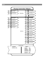
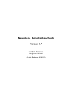
Fig.1b:
Pump Controller Object
nv1
nviPumpSetpoint
SNVT_switch
nv2
nviPumpOpMode
SNVT_hvac_mode
Mandatory
nv3
nvoPumpCapacity
SNVT_lev_percent
nv4
nvoEffOpMode
SNVT_hvac_mode
nv5
nvoControlMode
SNVT_dev_c_mode
nv6
nviPumpOvdStop
SNVT_switch
nv13
nvoPumpStatus
SNVT_dev_status
nv7
nviOvdSpeed
SNVT_lev_percent
nv14
nvoPressure
SNVT_press
nv8
nviOvdPress
SNVT_press
nv15
nvoFlow
SNVT_flow_p
nv10
nviRemotePress
SNVT_press
nv16
nvoSpeed
SNVT_rpm
nv12
nviRemoteTemp
SNVT_temp_p
nv17
nvoPumpOverride
SNVT_switch
nv18
nvoRuntime
SNVT_time_hour
nv19
nvoPumpFault
SNVT_dev_fault
nv20
nvoMaintenance
SNVT_dev_maint
nv21
nvoFluidTemp
SNVT_temp_p
nv22
nvoPower
SNVT_power
nv23
nvoPowerKilo
SNVT_power_kilo
nv24
nvoEnergyConsum
SNVT_elec_kwh
Optional
Configuration
Mandatory
nciSndHrtBt scpt49
nroPumpChar scpt233
Optional
nciRcvHrtBt
nciMinOutTm
nciObjMajVer
nciObjMinVer
nciControlMode
nciRemMinPress
nciRemMaxPress
nciRemMinTemp
nciRemMaxTemp
nciPressTemp
nciSetpPreset
scpt48
scpt52
scpt167
scpt168
scpt238
scpt239
scpt240
scpt243
scpt244
ucpt
scpt213
Fig.3a:
TOP-ED
DP
L
PLR
N PE
SSM
SL
(Slave)
1∼230V
⊥ In +24V Ext.off
0...10V
P1 ≥ 500W
min. 2x0,75mm²
DP
L
LON
N PE
SSM
1∼230V
MA
(Master)
⊥ In +24V Ext.off
0...10V
P1 ≥ 500W
13,5
11
7
LON-Bus
Fig.3b:
IF-Modul
SSM
Netzspannung
Attention
Mains Voltage
!
Achtung
Attention
1 - 230V
Achtung
LN
Option
IF-Modul
p nnung
Attention
Mains Voltage
Fig.3c:
IP-E/DP-E
Fig.3d:
IL-E/DL-E
Fig.4:
~15
mm
~15
Fig.5:
Fig.6:
Stratos
1
Top-E
VeroLine IP-E
CronoLine IL-E
mm
de
Einbau- und Betriebsanleitung
en
Installation and operating instructions
3
36
Deutsch
1 Allgemeines
Einbauund Betriebsanleitung
1.1 Über dieses Dokument
Die Sprache der Originalbetriebsanleitung ist Deutsch. Alle weiteren Sprachen
dieser Anleitung sind eine Übersetzung der Originalbetriebsanleitung.
Die Einbau- und Betriebsanleitung ist Bestandteil des Produktes. Sie ist jederzeit in Produktnähe bereitzustellen. Das genaue Beachten dieser Anweisung ist
Voraussetzung für den bestimmungsgemäßen Gebrauch und die richtige Bedienung des Produktes.
Die Einbau- und Betriebsanleitung entspricht der Ausführung des Produktes
und dem Stand der zugrunde gelegten sicherheitstechnischen Normen bei
Drucklegung.
Diese Einbau- und Betriebsanleitung ist als Ergänzung zur Einbau- und
Betriebsanleitung der an den LON-Bus angeschlossenen Pumpen zu betrachten.
2 Sicherheit
Diese Betriebsanleitung enthält grundlegende Hinweise, die bei Aufstellung und
Betrieb zu beachten sind. Daher ist diese Betriebsanleitung unbedingt vor Montage und Inbetriebnahme vom Monteur sowie dem zuständigen Betreiber zu
lesen.
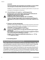
2.1 Kennzeichnung von Hinweisen in der Betriebsanleitung
Symbole:
Allgemeines Gefahrensymbol
Gefahr durch elektrische Spannung
HINWEIS: ...
Signalwörter:
GEFAHR!
Akut gefährliche Situation.
Nichtbeachtung führt zu Tod oder schwersten Verletzungen.
WARNUNG!
Der Benutzer kann (schwere) Verletzungen erleiden. 'Warnung' beinhaltet,
dass (schwere) Personenschäden wahrscheinlich sind, wenn der Hinweis
missachtet wird.
Einbau- und Betriebsanleitung Wilo-Control IF-Modul LON / IF-Modul Stratos LON
3
Deutsch
VORSICHT!
Es besteht die Gefahr, die Pumpe/Anlage zu beschädigen. 'Vorsicht' bezieht
sich auf mögliche Produktschäden durch Missachten des Hinweises.
HINWEIS: Ein nützlicher Hinweis zur Handhabung des Produktes. Er macht auch
auf mögliche Schwierigkeiten aufmerksam.
2.2 Sicherheitshinweise für Inspektions- und Montagearbeiten
Bei allen Arbeiten an der/den Pumpe(n) sind die Sicherheitshinweise der
Betriebsanleitung der gesamten Anlage zu beachten.
WARNUNG! Gefahr durch Stromschlag
Gefährdungen durch elektrische Energie sind auszuschließen.
Arbeiten an Anlage/Pumpe(n) dürfen nur bei mechanischem Stillstand, in
spannungslosem Zustand und mit geeigneten Werkzeugen ausgeführt werden.
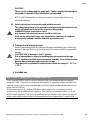
3 Transport und Zwischenlagerung
Bei Erhalt Pumpe/Anlage sofort auf Transportschäden überprüfen. Bei Feststellung von Transportschäden sind die notwendigen Schritte innerhalb der entsprechenden Fristen beim Spediteur einzuleiten.
VORSICHT! Beschädigungsgefahr für das IF-Modul!
Gefahr der Beschädigung durch unsachgemäße Handhabung bei Transport
und Lagerung.
• Die IF-Module sind bei Transport und Zwischenlagerung gegen Feuchtigkeit,
Frost und mechanische Beschädigung zu schützen.
• Sie dürfen keinen Temperaturen außerhalb des Bereiches von - 10°C bis
+ 70°C ausgesetzt werden.
4 Verwendungszweck
Wilo-Control IF-Modul LON, IF-Modul Stratos LON
Das IF-Modul LON dient zum Anschluss von elektronisch geregelten Nassläufer- oder
Trockenläuferpumpen an ein LON-Netzwerk. Über den LON-Bus können der Pumpe Sollwerte, Betriebsarten und die Daten externer Sensoren vorgegeben werden und aktuelle
Betriebsdaten und Fehlermeldungen können von der Pumpe übermittelt werden.
Gleichzeitig bietet das IF-Modul LON die Möglichkeit, über eine weitere Schnittstelle DP
zwei Pumpen zu einer Doppelpumpe zusammenzuschalten. Diese Schnittstelle ist separat ausgeführt, es handelt sich nicht um eine auf LON basierende Schnittstelle. Deshalb
wird der LON-Bus für die Doppelpumpenschnittstelle nicht belastet und die Slave-Pumpe
kann mit einem kostengünstigen IF-Modul PLR ausgestattet werden.
4
WILO SE 04/2014
Deutsch
Anschließbare Pumpentypen
Nassläuferpumpen
Trockenläuferpumpen
• Wilo-TOP-E mit IF-Modul LON
• Wilo-TOP-ED mit IF-Modul LON
und IF-Modul PLR
• Wilo-Stratos mit IF-Modul Stratos LON
• Wilo-Stratos-D mit IF-Modul Stratos
LON und IF-Modul Stratos PLR
• Wilo-Stratos-Z mit IF-Modul Stratos LON
• Wilo-Stratos-ZD mit IF-Modul Stratos
LON und IF-Modul Stratos PLR
Tabelle 4.1
•
•
•
•
Wilo-VeroLine-IP-E mit IF-Modul LON
Wilo-VeroTwin-DP-E mit IF-Modul LON
Wilo-CronoLine-IL-E mit IF-Modul LON
Wilo-CronoTwin-DL-E mit IF-Modul LON
und IF-Modul PLR
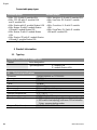
5 Angaben über das Erzeugnis
5.1 Typenschlüssel
Beispiel: Wilo-Control IF-Modul LON
Control
5.2
Baureihenbezeichnung
Typenbezeichnung:
IF-Modul LON
IF-Modul Stratos LON
Technische Daten
Prozessor:
Speicher:
Transceiver:
Takt:
Firmware:
Spannungsversorgung:
Stromaufnahme:
Umgebungstemperatur:
Buskabel:
max. Länge Buskabel:
Programm-ID (Software):
TMPN3150B1AF bzw. CY7C53150
32 KB Flash
FTT 10A
10 MHz
Version 7
5 V= und 15 V= über die Pumpe
ca. 30 mA
0°C – 40°C
JY(St) Y 2x2x0,8
• 900 m bei Bustopologie mit max. 3 m langen Stichleitungen
• 450 m bei freier Topologie, dabei max. 250 m zwischen 2 untereinander kommunizierenden Knoten
9F:FF:CC:51:14:06:04:04
Einbau- und Betriebsanleitung Wilo-Control IF-Modul LON / IF-Modul Stratos LON
5
Deutsch
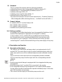
5.3 Standards
Das IF-Modul LON entspricht folgenden Standards:
• LonMark Application Layer Interoperability Guidelines Version 3.2
• LonMark Layers 1-6 Interoperability Guidelines Version 3.2
• LonMark node object 0000_20
• LonMark pump controller object 8120_10
• LonMark Resource Files Version 13.00
Die gesamte Dokumentation ist unter www.wilo.de (- Produkte, - Wilo Schaltgeräte, - LonMark Functional Profile ...) zu finden.
5.4 Lieferumfang
• IF-Modul LON oder IF-Modul Stratos LON
• Metallische Kabelverschraubung PG 7
• Metallische Kabelverschraubung PG 9
• Einbau- und Betriebsanleitung
5.4.1 Auslieferungszustand
Gemäß den LonMark Application Layer Interoperability Guidelines wird das IFModul LON im Zustand “Application unconfigured” ausgeliefert. In diesem
Zustand kann das IF-Modul LON über den LON-Bus angesprochen werden, aber
die Applikation, die normalerweise die Kommunikation mit der Pumpe ausführt,
ist noch nicht in Betrieb. Somit ist nach dem Aufstecken des IF-Moduls LON und
dem Einschalten der Stromversorgung der Pumpe noch keine Aktivität zu
sehen.
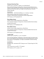
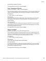
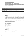
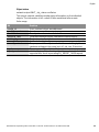
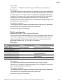
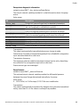
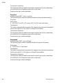
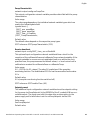
6 Beschreibung und Funktion
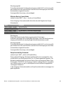
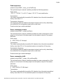
6.1 Beschreibung der Objekte
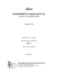
Im IF-Modul LON sind 2 Objekte realisiert, das Knoten-Objekt und das PumpenObjekt. Das Knoten-Objekt dient zur Steuerung einzelner Objekte innerhalb des
Knotens, hier werden auch zentral Fehler signalisiert, die in den einzelnen
Objekten auftreten.
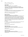
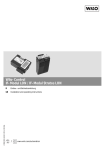
Fig.1a zeigt das Knoten-Objekt (Node Object) mit den zugehörigen Netzwerkvariablen und Fig.1b zeigt das Pumpen-Objekt (Pump Controller Object) mit
den zugehörigen Netzwerkvariablen.
HINWEIS:
• Doppelpumpen sind immer mit dem integrierten Doppelpumpenmanagement
zu betreiben.
• Bei Doppelpumpen wird das IF-Modul LON an den Master angeschlossen.
• Wird bei Doppelpumpen das integrierte Doppelpumpenmanagement nicht
benutzt, so sind die beiden Antriebe wie zwei separate Einzelpumpen zu behandeln. In diesem Fall sind zwei IF-Module LON erforderlich.
• Steuerfunktionen beziehen sich auf die Doppelpumpe als gesamtes Aggregat.
6
WILO SE 04/2014
Einbau- und Betriebsanleitung Wilo-Control IF-Modul LON / IF-Modul Stratos LON
O
nviRemotePress
nviRemoteTemp O
O
nviOvdPress
SNVT_temp_p
SNVT_press
SNVT_press
SNVT_lev_percent 1
O
nviOvdSpeed
1
1
1
no
no
no
no
no
no
12 yes
10 yes
8
7
6
SNVT_switch
nviPumpOvdStop O
1
2
SNVT_hvac_mode 1
1
1
nviPumpOpMode M
1
SNVT_obj_request 0
SNVT_switch
M
-
-
-273.17
... +327.66 °C
0.01°C
-3276.8
0.1 kPa
... +3276.6 kPa
.state: 0 – 1
.value: 0.0 – 100.0%
0x7FFF
0x7FFF
0x7FFF
0x7FFF
0x7FFF
0x7FFF
0x7FFF
0x7FFF
Eff. Resol.: 0.1°C
Eff. Resol.: 0.981kPa
-273.1 – 327.6 °C
0 - 100%
Eff. Resolution: 0.5%
Range depends on
Pumptype.
Eff. Resol.: 0.981kPa
0–3276.6kPa
HVAC_AUTO 0xFF
HVAC_AUTO
(HVAC_NUL) HVAC_MRNG_WRMUP
HVAC_PRE_COOL
HVAC_ECONOMY
.state: 0xFF
.state: 0xFF .state: 0 – 1
.value: 0xFF
.value: 0.0 – 100.0%
SCPTsetpoint -
Resolution Default Value Invalid Data Data Range and
effective
resolution WILO
.object_id: 0 - 1
.object_request:
RQ_NORMAL
RQ_DISABLED
RQ_ENABLE
RQ_UPDATE_STATUS
RQ_REPORT_MASK
RQ_CLEAR_STATUS
.state: 0 – 1
.value: 0.0
... +100.0%
-163.84
0.005 %
... +163.83 %
-3276.8
0.1 kPa
... +3276.6 kPa
(hvac_t)
.state: 0 – 1
.value: 0.0
- 100.0%
enum 0 ... 17
-
Object No. Receive Data Range
Heartbeat and Units
nviPumpSetpoint M
nviRequest
InputMand. NVT
Networkvariable Opt.
Deutsch
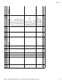
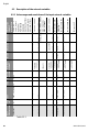
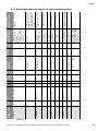
6.2 Beschreibung der Netzwerkvariablen
6.2.1 Wertebereiche und Auflösungen der Netzwerkvariablen Eingänge
Tabelle 6.2.1
7
8
1
1
SNVT_flow_p
SNVT_elec_kWh
SNVT_power
O
nvoEnergyConsum O
O
O
O
O
O
M
nvoFlow
nvo Power
nvoPowerKilo
nvoRuntime
nvoSpeed
nvoFluidTemp
nvoControlMode
1
1
1
1
SNVT_dev_c_mode 1
SNVT_temp_p
SNVT_rpm
SNVT_time_hour
SNVT_power_kilo
1
SNVT_press
O
nvoPressure
1
1
SNVT_obj_status
yes
5
yes
21 no
16 no
18 no
23 no
22 no
24 no
15 no
14 no
3
Obj No. Send
Heartbt /
Ack
0 2 yes
SNVT_lev_percent
M
Mand. NVT
Opt.
nvoPumpCapacity M
nvoStatus
OutputNetworkvariable
yes
yes
yes
yes
yes
yes
yes
yes
yes
yes
1 rpm
1h
0.1 kW
0.1 W
-273.17
0.01 °C
– 327.66 °C
ENUM 0 – 29
(device_c_mode_t)
0 – 65535 rpm
0 – 65535 h
0 – 6553.5 kW
0 – 6553.5 W
1 kWh
0.01 m3/h
0 – 655.34 m3/h
0 – 65535 kWh
0.1 kPa
0.005 %
0x7FFF Range depends on
Pumptype
Res. :0.981 kPa
0xFFFF Range depends on
Pumptype
Res : 0.1 m3/h
0 – 65535 kWh
Res: 1 kWh
0 – 6553W
Res: min. 1 W
0 – 65.5 kW
Res: 0.1 kW
0 – 65535 h
Res: 10 h
0 – 65535 rpm
Res: min.1 rpm
0x7FFF -50 °C – 205°C
Res : min. 0.1 °C
DCM_SPEED_CONST
0xFF
DCM_PRESS_CONST
DCM_PRESS_COMP
DCM_PRESS_AUTO
DCM_NUL
invalid_id
invalid_request
disabled
electrical_fault
unable_to_measure
manual_control
in_alarm
0x7FFF 0 – 100.0%
Res: 0.2%
-
immediately
2 % of nroPumpChar.speedMax
5 °C
10 h
10 % of max. Power
10 % of max. Power
1 kWh
5 % of
nroPumpChar.flowMax
5 % of nroPumpChar.pressMax
or 2 % of nroPumpChar.speedMax resp.,
control mode changes
5 % of
nroPumpChar.pressMax
Send upon nviRequest:
update
Resolution Invalid Range and effective Send when value
Data
resolution WILO
changes more than
-3276.8
– 3276.6 kPa
-163.84
– 163.83 %
Min. Data Range
Send and Units
Time
yes
Deutsch
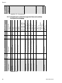
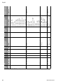
6.2.2 Wertebereiche und Auflösungen der Netzwerkvariablen Ausgänge
Tabelle 6.2.2
WILO SE 04/2014
Einbau- und Betriebsanleitung Wilo-Control IF-Modul LON / IF-Modul Stratos LON
17 no
SNVT_switch
O
1
4
SNVT_hvac_mode 1
M
yes
13 yes
SNVT_dev_status 1
O
O
O
Obj No. Send
Heartbt /
Ack
SNVT_dev_maint 1 20 no
SNVT_dev_fault 1 19 no
Mand. NVT
Opt.
yes
yes
yes
Min.
Send
Time
yes
yes
-
-
-
Range and effective
resolution WILO
service_required
sf_voltage_low
sf_voltage_high
sf_phase
sf_no_fluid
df_motor_temp
df_motor_failure
df_pump_blocked
df_elect_temp
df_elect_failure_nf
df_elect_failure
df_sensor_failure
device_fault
supply_fault
speed_low
speed_high
setpt_out_of_range
local_control
running
remote_press
remote_temp
HVAC_AUTO
0xFF
HVAC_MRNG_WRMUP
HVAC_PRE_COOL
HVAC_ECONOMY
HVAC_NUL
.state: 0xFF .state: 0 – 1
.value: 0.0%, 100.0%, 0xFF
-
Resolution Invalid
Data
.state: 0 – 1
.value: 0.0-100.0%,
ENUM 0 – 17
(hvac_t)
bitset
bitset
bitset
Data Range
and Units
immediately
immediately
immediately
immediately
immediately
Send when value
changes more than
Deutsch
Tabelle 6.2.2, Fortsetzung
9
10
1
1
1
SCPTmaxRemoteTempSetpoint
UCPTPressTemp
SCPTsetpoint
O
U
O
nciPressTemp
nciSetpPreset
nciRemMaxTemp
243
1
SCPTminRemoteTempSetpoint
O
nciRemMinTemp
240
SCPTmaxRemotePressureSetpoint 1
O
nciRemMaxPress
239
SCPTminRemotePressureSetpoint 1
O
nciRemMinPress
238
1
SCPTdeviceControlMode
O
nciControlMode
1
O
nciMinOutTm
213
244
52
49
SCPTminSendTime
M
nciSndHrtBt
1
O
O
nciLocation
nciRcvHrtBt
SCPTmaxSendTime
17
48
22
0
1
0
0–0d17h59m59s
eff. Res: 1s
0–6553s
eff. Res: 1s
0–6553s
eff. Res: 1s
0–6553s
eff. Res: 1s
DCM_SPEED_CONST
DCM_PRESS_CONST
DCM_PRESS_COMP
DCM_PRESS_AUTO
0 – 3276.7 kPa
eff. Res: 0.981 kPa
0 – 3276.7 kPa
eff. Res: 0.981 kPa
-273.1 – 327.6 °C
eff. Res: 0.1°C
-273.1 – 327.6 °C
eff. Res: 0.1°C
.TempMin, .TempMax:
0 – 110 °C
eff. Res: 0.1°C
.PressMin, .PressMax:
0 – 3276.7 kPa
eff. Res: 0.981kPa
.state: 0–1
.value: 0–255
Object Number Data Range and effective
resolution WILO
SCPTlocation
SCPTmaxRcvTime
Input Configuration Variable Mandatory / CPT / NVT
Optional /
User
SCPTmaxSndT
nciMaxStsSendT
O
nvoPumpOverride
nvoEffOpMode
nvoPumpStatus
nvoMaintenance
nvoPumpFault
OutputNetworkvariable
Deutsch
Tabelle 6.2.2, Fortsetzung
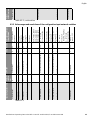
6.2.3 Wertebereiche und Auflösungen der Netzwerkvariablen
Konfigurationseingänge
Tabelle 6.2.3
WILO SE 04/2014
Deutsch
6.2.4 Wertebereiche und Auflösungen der Netzwerkvariablen
Konfigurationsausgänge
Output
Mandat./
Configuration Optional
Variable
CPT/NVT
Object Number Value
nciDevMajVer
nciDevMinVer
nroPumpChar
O
O
M
SCPTdevMajVer
SCPTdevMinVer
SCPTpumpCharacteristic
0
0
1
165
166
233
nciObjMajVer
nciObjMinVer
O
O
SCPTobjMajVer
SCPTobjMinVer
1
1
167
168
02
00
depends on
pumptype
02
00
6.2.5 Beschreibung der Netzwerkvariablen
Objekt-Request
network input SNVT_obj_request nviRequest
Diese Eingangs-Netzwerkvariable veranlasst verschiedene Operationen, die
den Knoten- und Objektstatus betreffen. Sie besteht aus 2 Bytes, dem ID-Byte
und dem Wert-Byte. Das ID-Byte gibt die Nummer des Objektes an, auf das sich
der Request bezieht. Der ID-Wert 0 bezieht sich auf das Knoten-Objekt, hier
haben Requests evtl. auch Auswirkungen auf alle anderen Objekte. Der ID-Wert
1 bezieht sich auf das pump-controller-Objekt.
Wertebereich
Wert
Funktion bei ID = 0
Funktion bei ID = 1
RQ_NORMAL
Normalbetrieb aller Objekte
RQ_DISABLED
RQ_ENABLE
RQ_UPDATE_STATUS
Stop aller Objekte
Enable des Knotenobjekts
Status Knotenobjekt aktualisieren (Oderverknüpfung über
alle Objekte)
Unterstützte Statusmeldungen Knotenobjekt (Oderverknüpfung über alle Objekte)
Bestimmte Statusmeldungen
in allen Objekten löschen
Normalbetrieb pump controller
Stop des pump controller
Enable des pump controller
Status pump controller aktualisieren
RQ_REPORT_MASK
RQ_CLEAR_STATUS
Unterstützte Statusmeldungen pump controller
Bestimmte Statusmeldungen
des pump controller löschen
Einbau- und Betriebsanleitung Wilo-Control IF-Modul LON / IF-Modul Stratos LON
11
Deutsch
Objekt-Status
network output SNVT_obj_status nvoStatus
Diese Ausgangs-Netzwerkvariable liefert Statusinformationen zu den einzelnen Objekten. Die Informationen sind Bit-Codiert. Alle Bits sind nach einem
Reset wieder gelöscht.
Wertebereich
Bit
Funktion
invalid_id
invalid_request
disabled
electrical_fault
unable_to_measure
Es wurde ein nicht existierendes Objekt angesprochen
Es wurde ein unbekannter Request gesendet
Das betreffende Objekt ist abgeschaltet
Das pump-controller-Objekt meldet einen elektrischen Fehler
Das pump-controller-Objekt kann nicht mit der Pumpe kommunizieren
Nur für das Knotenobjekt
Das pump-controller-Objekt wird durch Hardware-Vorgaben
an der Pumpe an der Steuerung gehindert (ext. Off, ext. Min, IRMonitor)
Das pump-controller-Objekt meldet einen Fehler
Signalisiert, daß nvoStatus aufgrund einer vorangegangenen
RQ_REPORT_MASK-Aufforderung die Status-Maske enthält,
also die Liste aller Bits, die unterstützt werden.
comm_failure
manual_control
in_alarm
report_mask
12
WILO SE 04/2014
Deutsch
Maximum Status Send Time
network input config SNVT_elapsed_tm nciMaxStsSendT
Diese optionale Eingangs-Konfigurations-Netzwerkvariable definiert einen
Zeittakt, in welchem die Objekt-Stati automatisch gesendet werden. Es werden
abwechselnd der Status des node-Objekts und der des pump-controllerObjekts gesendet.
Wertebereich
0d0h0m0s0ms – 0d17h59m59s999ms (in 1 s-Schritten). Der Wert
0d0h0m0s0ms schaltet das automatische Senden aus.
Startwert: 0d0h0m0s0ms (automatisches Senden ausgeschaltet)
SCPT Reference: SCPTmaxSendT (22)
Device Major Version
network output config unsigned short nciDevMajVer
Diese optionale Ausgangs-Konfigurations-Netzwerkvariable liefert das Highbyte der Modulversion.
SCPT Reference: SCPTdevMajVer (165)
Device Minor Version
network output config unsigned short nciDevMinVer
Diese optionale Ausgangs-Konfigurations-Netzwerkvariable liefert das Lowbyte der Modulversion.
SCPT Reference: SCPTdevMinVer (166)
Location Label
network input config SNVT_str_asc nciLocation
Diese optionale Eingangs-Konfigurations-Netzwerkvariable kann genutzt werden, um Informationen über den Einbauort der Pumpe abzuspeichern, die über
den im Neuron Chip abgelegten, nur 6Byte umfassenden Informationsstring
hinausgehen.
Wertebereich
Beliebiger, NUL-terminierter ASCII-String von max. 31 Bytes Länge (incl. NUL).
Startwert
ASCII-String, der nur aus NUL ("\0") besteht.
SCPT Reference: SCPT_location (17)
Einbau- und Betriebsanleitung Wilo-Control IF-Modul LON / IF-Modul Stratos LON
13
Deutsch
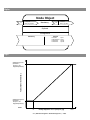
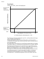
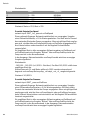
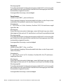
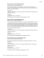
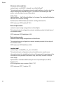
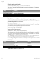
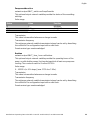
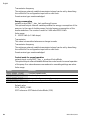
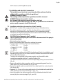
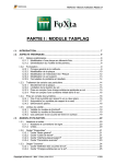
Pump Setpoint
network input SNVT_switch nviPumpSetpoint
Tatsächlicher Sollwert [%]
Sollwertobergrenze
(Hersteller- ,
Pumpen- und
Regelartspezifisch)
Sollwertuntergrenze
(Hersteller- ,
Pumpen- und
Regelartspezifisch)
STOP
X
Pump Setpoint nviPumpSetpoint [%]
100%
X = ( Sollwertuntergrenze / Sollwertobergrenze ) * 100%
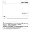
Diese Eingangs-Netzwerkvariable dient zum Ein- und Ausschalten der Pumpe
und zur Vorgabe eines Sollwertes.
Die Netzwerkvariable besteht aus einem Status-Byte, in welchem der Einschaltzustand übertragen wird, und aus einem Werte-Byte, in welchem der Sollwert übertragen wird.
Bei Vorgabe eines Status-Bytes von 0 ist die Pumpe ausgeschaltet, bei Vorgabe
eines Status-Bytes von 1 hängt der Einschaltzustand noch vom Werte-Byte ab.
Bei Vorgabe eines Sollwertes von 0% wird die Pumpe ausgeschaltet, bei Vorgabe eines Sollwertes größer 0% ist die Pumpe eingeschaltet, wenn das StatusByte 1 ist. Der Sollwert kann in 0,5%-Schritten verändert werden.
Bei Vorgabe von Sollwerten oberhalb der Sollwertobergrenze wird auf die Sollwertobergrenze begrenzt, entsprechend wird bei Vorgabe von Sollwerten
unterhalb der Sollwertuntergrenze auf die Sollwertuntergrenze begrenzt.
Die Sollwertober- und Sollwertuntergrenzen können sich ändern, wenn die
14
WILO SE 04/2014
Deutsch
Pumpe mit einem externen Sensor betrieben wird
(siehe nviRemotePress, nciRemMinPress und nciRemMaxPress).
Wertebereich
Status
Wert
Funktion
0
1
1
1
0 – 255
0
1 – 200
201 - 255
STOP
STOP
0,5 – 100,0%
100,0%
Startwert: Status = 1, Wert = 200 = 100,0%. Startwert entspricht der Vorgabe,
die im Konfigurationsparameter SCPTsetpoint nichtflüchtig abgespeichert werden kann.
Requested Pump-Operating Mode
network input SNVT_hvac_mode nviPumpOpMode
Diese Eingangs-Netzwerkvariable dient zur Vorgabe eines Betriebsmodus. Wird
ein Betriebsmodus vorgegeben, der nicht definiert oder ungültig ist, verbleibt
die Pumpe im aktuellen Modus.
Wertebereich
Wert
Funktion
Bemerkung
HVAC_AUTO
Normalbetrieb
HVAC_MRNG_WRMUP
HVAC_PRE_COOL
HVAC_ECONOMY
Aufwärmbetrieb
Abkühlbetrieb
Energiesparbetrieb
Sollwert über
nviPumpSetpoint
Maximale Drehzahl
Maximale Drehzahl
Drehzahl Absenkbetrieb
(Pumpentypspezifisch)
HVAC_NUL
Ungültig
Startwert: HVAC_AUTO
Pump Capacity
network output SNVT_lev_percent nvoPumpCapacity
Diese Ausgangs-Netzwerkvariable liefert den aktuellen Arbeitspunkt der
Pumpe als auf den maximalen Sollwert bezogenen Prozentwert.
Bei Verwendung eines externen Druck- oder Temperatursensors liefert diese
Variable den Sensorwert als auf den maximalen Sensorwert bezogenen
Prozentwert.
Einbau- und Betriebsanleitung Wilo-Control IF-Modul LON / IF-Modul Stratos LON
15
Deutsch
Wertebereich
-163,840% – 163,830% (in 0,02%-Schritten). Der Wert 163,835% stellt einen
ungültigen Wert dar.
Übertragung
Dieser Wert wird automatisch übertragen, wenn die Abweichung vom zuletzt
übertragenen Wert mehr als 5% des Wertes in nroPumpChar.pressMax (bei Differenzdruckregelung) oder 2% des Wertes in nroPumpChar.speedMax (bei
Drehzahlsteller) beträgt. Außerdem wird dieser Wert regelmäßig übertragen,
wenn der Konfigurationseingang nciSndHrtBt mit einem gültigen Zeittakt
beschrieben wurde. Ebenso wird dieser Wert übertragen, wenn durch vorrangige Vorgaben oder Anschließen eines externen Sensors die Regelart geändert
wurde.
Übertragungstakt
Durch Beschreiben des Konfigurationseingangs nciMinOutTm mit einem gültigen Zeittakt kann die minimale Zeit zwischen zwei Übertragungen einer Netzwerkvariablen eingestellt werden.
Voreingestellter Servicetyp: acknowledged
Effective Operating Mode
network output SNVT_hvac_mode nvoEffOpMode
Diese Ausgangs-Netzwerkvariable liefert den aktuellen Betriebsmodus der
Pumpe. Dieser Wert entspricht der Vorgabe in der Eingangs-Netzwerkvariablen
nviPumpOpMode, wenn nicht über lokale Vorgaben an der Pumpe (ext. off, ext.
min oder IR-Monitor) ein anderer Betriebsmodus erzwungen wird.
Wertebereich
Wert
Funktion
Bemerkung
HVAC_AUTO
Normalbetrieb
HVAC_MRNG_WRMUP
HVAC_PRE_COOL
HVAC_ECONOMY
Aufwärmbetrieb
Abkühlbetrieb
Energiesparbetrieb
HVAC_OFF
Offlinebetrieb
Sollwert über
nviPumpSetpoint
Maximale Drehzahl
Maximale Drehzahl
Drehzahl Absenkbetrieb
(Pumpentypspezifisch)
Ext. Off oder Manueller
Betrieb über IR-Monitor
HVAC_NUL
Ungültig
Übertragung
Dieser Wert wird bei jeder Änderung automatisch übertragen.
Außerdem wird dieser Wert regelmäßig übertragen, wenn der Konfigurationseingang nciSndHrtBt mit einem gültigen Zeittakt beschrieben wurde.
16
WILO SE 04/2014
Deutsch
Übertragungstakt
Durch Beschreiben des Konfigurationseingangs nciMinOutTm mit einem gültigen Zeittakt kann die minimale Zeit zwischen zwei Übertragungen einer Netzwerkvariablen eingestellt werden.
Voreingestellter Servicetyp: acknowledged
Effective Device-Control Mode
network output SNVT_dev_c_mode nvoControlMode
Diese Ausgangs-Netzwerkvariable liefert die aktuelle Regelart der Pumpe.
Wertebereich
Wert
Funktion
DCM_SPEED_CONST
DCM_PRESS_CONST
DCM_PRESS_COMP
DCM_PRESS_AUTO
Drehzahlsteller
Differenzdruck konstant
Differenzdruck volumenstromabhängig
Differenzdruck temperaturabhängig
Übertragung
Dieser Wert wird bei jeder Änderung automatisch übertragen.
Außerdem wird dieser Wert regelmäßig übertragen, wenn der Konfigurationseingang nciSndHrtBt mit einem gültigen Zeittakt beschrieben wurde.
Übertragungstakt
Durch Beschreiben des Konfigurationseingangs nciMinOutTm mit einem gültigen Zeittakt kann die minimale Zeit zwischen zwei Übertragungen einer Netzwerkvariablen eingestellt werden.
Voreingestellter Servicetyp: acknowledged
Pump Override Stop Command
network input SNVT_switch nviPumpOvdStop
Diese optionale Eingangs-Netzwerkvariable stellt eine vorrangige Ein-/Ausschaltfunktion zur Verfügung und ist für z. B. Wartungsarbeiten gedacht. Die
Netzwerkvariable besteht aus einem Status-Byte und aus einem Werte-Byte.
Die Vorgabe “OVDSTOP” hat Vorrang vor dem in nviPumpSetpoint vorgegebenen Sollwert sowie vor den in nviOvdSpeed und nviOvdPress vorgegebenen
vorrangigen Sollwerten.
In der Ausgangs-Netzwerkvariable nvoPumpOverride wird eine vorrangige Vorgabe signalisiert.
Einbau- und Betriebsanleitung Wilo-Control IF-Modul LON / IF-Modul Stratos LON
17
Deutsch
Wertebereich
Status
Wert
Funktion
0
1
1
255
0 – 255
0
1 – 255
0 – 255
NORMAL
NORMAL
OVDSTOP
ungültig (NORMAL)
Startwert: Status = 255, Wert = 255
Override Setpoint for Speed
network input SNVT_lev_percent nviOvdSpeed
Diese optionale Eingangs-Netzwerkvariable dient zur vorrangigen Vorgabe
eines Drehzahlsollwertes, z. B. für Wartungsarbeiten. Der Wert wird in Prozent
des maximalen Wertes der Pumpe vorgegeben. Wenn ein gültiger Wert empfangen wird , wird der über nviPumpSetpoint oder nviOvdPress vorgegebene Sollwert überschrieben und automatisch auf die Regelart Drehzahlsteller
umgeschaltet.
Ein ungültiger Wert in allen vorrangigen Sollwertvorgaben nviOvdSpeed und
nviOvdPress sowie eine Vorgabe “Normal” über nviPumpOvdStop setzt die
Pumpe zurück in den Normalzustand.
In der Ausgangs-Netzwerkvariablen nvoPumpOverride wird eine vorrangige
Vorgabe signalisiert.
Wertebereich
-163,84% - 163,83% (in 0,005%-Schritten). Der Wert 163,835% stellt einen
ungültigen Wert dar.
Werte kleiner als 0% und Werte größer als 100% werden entsprechend
begrenzt und nvoPumpStatus.pump_ctrl.setpt_out_of_range wird gesetzt.
Startwert: 163,835%
Override Setpoint for Pressure
network input SNVT_press nviOvdPress
Diese optionale Eingangs-Netzwerkvariable dient zur vorrangigen Vorgabe
eines Differenzdrucksollwertes, z. B. für Wartungsarbeiten. Der Wert wird in
Prozent des maximalen Wertes der Pumpe vorgegeben. Wenn ein gültiger Wert
empfangen wird, wird der über nviPumpSetpoint oder nviOvdSpeed vorgegebene Sollwert überschrieben und automatisch auf die Regelart Differenzdruck
konstant umgeschaltet.
Ein ungültiger Wert in allen vorrangigen Sollwertvorgaben nviOvdSpeed und
nviOvdPress sowie eine Vorgabe “Normal” über nviPumpOvdStop setzt die
Pumpe zurück in den Normalzustand. In der Ausgangs-Netzwerkvariablen
nvoPumpOverride wird eine vorrangige Vorgabe signalisiert.
18
WILO SE 04/2014
Deutsch
Wertebereich
-3276,8 – 3276,6 kPa (in 0,1 kPa-Schritten). Der Wert 3276,7 kPa stellt einen
ungültigen Wert dar.
Werte außerhalb des für die jeweilige Pumpe gültigen Bereichs werden entsprechend begrenzt und nvoPumpStatus.pump_ctrl.setpt_out_of_range wird
gesetzt.
Startwert: 3276,7kPa
Remote Pressure-Sensor Input
network input SNVT_press nviRemotePress
Diese optionale Eingangs-Netzwerkvariable erlaubt den Einsatz eines externen
Differenzdruck-Sensors für die Regelung der Pumpe. Bei Empfang eines gültigen Wertes schaltet die Pumpe automatisch auf die Regelart Differenzdruck
konstant um. Die Regelung mit einem externen Sensor wird in der Netzwerkvariablen nvoPumpStatus.pump_ctrl.remote_press angezeigt.
Die Ausgangs-Netzwerkvariable nvoPumpCapacity zeigt dann den aktuellen
Sensor-Istwert in Prozent vom Maximum des Sensorbereiches an. Die Ausgangs-Netzwerkvariable nvoPressure liefert immer den von der Pumpe intern
ermittelten Differenzdruck-Istwert, der durchaus vom Sensorwert abweichen
kann. Dies soll zur Analyse des Systemverhaltens dienen. Bei Benutzung der
Netzwerk-Eingangsvariablen nviRemotePress wird der Differenzdruck-Sollwert
weiterhin über die Eingangs-Netzwerkvariable nviPumpSetpoint vorgegeben.
Wenn an die Eingangs-Netzwerkvariable nviRemotePress ein ungültiger Wert
gesendet wird oder länger als in nciRcvHrtBt festgelegt kein neuer Wert empfangen wurde, kehrt die Pumpe zur internen Regelung und zu der in nciControlMode festgelegten Regelart zurück.
Der vorrangige Sollwerteingang nviOvdSpeed setzt die Regelung mit externem
Sensor ebenfalls außer Kraft.
Vorrang nviRemotePress vor nviRemoteTemp.
Achtung: Für eine stabile Regelung muß nviRemotePress alle 3s gesendet werden. Aber selbst dann kann nicht für alle Pumpentypen garantiert werden, daß
die Regelung stabil läuft.
Wertebereich
-3276,8 – 3276,6 kPa (in 0,1 kPa-Schritten). Der Wert 3276,7 kPa stellt einen
ungültigen Wert dar.
Startwert: 3276,7 kPa.
Remote Temperature-Sensor Input
network input SNVT_temp_p nviRemoteTemp
Diese optionale Eingangs-Netzwerkvariable erlaubt den Einsatz eines externen
Temperatur-Sensors für die Regelung der Pumpe. Bei Empfang eines gültigen
Wertes schaltet die Pumpe automatisch auf die Regelart Differenzdruck tempe-
Einbau- und Betriebsanleitung Wilo-Control IF-Modul LON / IF-Modul Stratos LON
19
Deutsch
raturabhängig um. Die Regelung mit einem externen Sensor wird in der Netzwerkvariablen nvoPumpStatus.pump_ctrl.remote_temp angezeigt.
Die Ausgangs-Netzwerkvariable nvoPumpCapacity zeigt dann den aktuellen
Sensor-Istwert in Prozent vom Maximum des Sensorbereiches an. Wenn an die
Eingangs-Netzwerkvariable nviRemoteTemp ein ungültiger Wert gesendet
wird oder länger als in nciRcvHrtBt festgelegt kein neuer Wert empfangen
wurde, kehrt die Pumpe zur internen Regelung und zu der in nciControlMode
festgelegten Regelart zurück.
Die vorrangigen Sollwerteingänge nviOvdSpeed und nviOvdPress setzen die
Regelung mit externem Sensor ebenfalls ausser Kraft.
Vorrang nviRemotePress vor nviRemoteTemp.
Wertebereich
-273,17 ... +327,66 °C (in 0,01 °C-Schritten). Der Wert 327,67 °C stellt einen
ungültigen Wert dar.
Startwert: 327,67 °C.
Pump-Status Diagnostic Information
network output SNVT_dev_status nvoPumpStatus
Diese Ausgangs-Netzwerkvariable liefert bitcodiert Informationen über den
Pumpenzustand.
Wertebereich
Bit
Beschreibung
device_fault
Pumpenfehler (siehe nvoPumpFault für genauere Information)
Versorgungsfehler (Netzspannung, Phase fehlt, Trockenlauf,
etc. Siehe nvoPumpFault für genauere Information)
Regeluntergrenze (Pumpe läuft auf minimaler Drehzahl, deshalb ist geforderter Arbeitspunkt nicht erreichbar)
Regelobergrenze (Pumpe läuft auf maximaler Drehzahl, deshalb ist geforderter Arbeitspunkt nicht erreichbar)
Sollwertüber-/unterschreitung
Lokalbetrieb (Durch ext. off, ext. min oder IR-Monitor)
Pumpe läuft
Regelung mit externem Drucksensor
Regelung mit externem Temperatursensor
supply_fault
speed_low
speed_high
setpt_out_of_range
local_control
running
remote_press
remote_temp
Übertragung
Dieser Wert wird bei jeder Änderung automatisch übertragen.
Außerdem wird dieser Wert regelmäßig übertragen, wenn der Konfigurationseingang nciSndHrtBt mit einem gültigen Zeittakt beschrieben wurde.
20
WILO SE 04/2014
Deutsch
Übertragungstakt
Durch Beschreiben des Konfigurationseingangs nciMinOutTm mit einem gültigen Zeittakt kann die minimale Zeit zwischen zwei Übertragungen einer Netzwerkvariablen eingestellt werden.
Voreingestellter Servicetyp: acknowledged
Pump Pressure
network output SNVT_press nvoPressure
Diese optionale Ausgangs-Netzwerkvariable liefert den von der Pumpe intern
ermittelten Differenzdruck zwischen den Pumpenflanschen.
Wertebereich
0 – 3276,6 kPa ( in 0,1 kPa-Schritten). Der Wert 3276,7 kPa stellt einen ungültigen Wert dar.
Übertragung
Dieser Wert wird automatisch übertragen, wenn die Abweichung vom zuletzt
übertragenen Wert mehr als 5% des Wertes in nroPumpChar.pressMax beträgt.
Übertragungstakt
Durch Beschreiben des Konfigurationseingangs nciMinOutTm mit einem gültigen Zeittakt kann die minimale Zeit zwischen zwei Übertragungen einer Netzwerkvariablen eingestellt werden.
Voreingestellter Servicetyp: unacknowledged
Pump Flow
network output SNVT_flow_p nvoFlow
Diese optionale Ausgangs-Netzwerkvariable liefert den von der Pumpe ermittelten Durchfluss.
Wertebereich
0 – 655,34 m3/h (in 0,01 m3/h-Schritten). Der Wert 655,35 m3/h stellt einen
ungültigen Wert dar.
Übertragung
Dieser Wert wird automatisch übertragen, wenn die Abweichung vom zuletzt
übertragenen Wert mehr als 5% des Wertes in nroPumpChar.flowMax beträgt.
Übertragungstakt
Durch Beschreiben des Konfigurationseingangs nciMinOutTm mit einem gültigen Zeittakt kann die minimale Zeit zwischen zwei Übertragungen einer Netzwerkvariablen eingestellt werden.
Voreingestellter Servicetyp: unacknowledged
Einbau- und Betriebsanleitung Wilo-Control IF-Modul LON / IF-Modul Stratos LON
21
Deutsch
Pump Speed
network output SNVT_rpm nvoSpeed
Diese optionale Ausgangs-Netzwerkvariable liefert die Drehzahl der Pumpe.
Wertebereich
0 – 65535 1/min (in eins 1/min-Schritten).
Übertragung
Dieser Wert wird automatisch übertragen, wenn die Abweichung vom zuletzt
übertragenen Wert mehr als 5% des Wertes in nroPumpChar.speedMax beträgt.
Übertragungstakt
Durch Beschreiben des Konfigurationseingangs nciMinOutTm mit einem gültigen Zeittakt kann die minimale Zeit zwischen zwei Übertragungen einer Netzwerkvariablen eingestellt werden.
Voreingestellter Servicetyp: unacknowledged
Pump Override Active
network output SNVT_switch nvoPumpOverride
Diese optionale Ausgangs-Netzwerkvariable liefert den Status der vorrangigen
Vorgaben.
Wertebereich
Status
Wert
Funktion
0
1
255
0
200
0 – 255
NORMAL
OVERRIDE
ungültig
Übertragung
Dieser Wert wird bei jeder Änderung übertragen.
Übertragungstakt
Durch Beschreiben des Konfigurationseingangs nciMinOutTm mit einem gültigen Zeittakt kann die minimale Zeit zwischen zwei Übertragungen einer Netzwerkvariablen eingestellt werden.
Voreingestellter Servicetyp: unacknowledged
Runtime
network output SNVT_time_hour nvoRuntime
Diese optionale Ausgangs-Netzwerkvariable liefert die Betriebsstunden der
Pumpe, bzw. bei Doppelpumpen die Zeit, in der mindestens eine Pumpe gelaufen ist. Nach 65535 Stunden beginnt die Zählung wieder bei 0 Stunden.
22
WILO SE 04/2014
Deutsch
Wertebereich
0 – 65535 h (in 10 h-Schritten), ( max. 2730 d oder 7,48 a).
Übertragung
Dieser Wert wird bei jeder Änderung übertragen.
Übertragungstakt
Durch Beschreiben des Konfigurationseingangs nciMinOutTm mit einem gültigen Zeittakt kann die minimale Zeit zwischen zwei Übertragungen einer Netzwerkvariablen eingestellt werden.
Voreingestellter Servicetyp: unacknowledged
Fault States of the Pump
network output SNVT_dev_fault nvoPumpFault
Diese optionale Ausgangs-Netzwerkvariable liefert bitcodiert Fehlerinformationen der Pumpe. Fehler können Gerätefehler oder Versorgungsfehler sein.
Wertebereich
Bit
Beschreibung
sf_voltage_low
sf_voltage_high
sf_phase
sf_no_fluid
df_motor_temp
df_motor_failure
df_pump_blocked
df_elect_failure_nf
df_elect_failure
df_sensor_failure
Versorgungsfehler, Netzspannung zu niedrig
Versorgungsfehler, Netzspannung zu hoch
Versorgungsfehler, Phase fehlt
Versorgungsfehler, Trockenlauf
Gerätefehler, Übertemperatur Motor
Gerätefehler, Motor defekt
Gerätefehler, Pumpe blockiert
Gerätefehler, Elektronikfehler
Gerätefehler, Elektronik defekt
Gerätefehler, Sensor defekt
Übertragung
Dieser Wert wird bei jeder Änderung übertragen.
Übertragungstakt
Durch Beschreiben des Konfigurationseingangs nciMinOutTm mit einem gültigen Zeittakt kann die minimale Zeit zwischen zwei Übertragungen einer Netzwerkvariablen eingestellt werden.
Voreingestellter Servicetyp: unacknowledged
Maintenance States
network output SNVT_dev_maint nvoMaintenance
Diese optionale Ausgangs-Netzwerkvariable liefert bitcodiert Serviceinformationen der Pumpe.
Einbau- und Betriebsanleitung Wilo-Control IF-Modul LON / IF-Modul Stratos LON
23
Deutsch
Wertebereich
service_required=Service erforderlich
Übertragung
Dieser Wert wird bei jeder Änderung übertragen.
Übertragungstakt
Durch Beschreiben des Konfigurationseingangs nciMinOutTm mit einem gültigen Zeittakt kann die minimale Zeit zwischen zwei Übertragungen einer Netzwerkvariablen eingestellt werden.
Voreingestellter Servicetyp: unacknowledged
Fluid Temperature
network output SNVT_temp_p nvoFluidTemp
Diese optionale Ausgangs-Netzwerkvariable liefert die Mediumtemperatur.
Wertebereich
-273,17 – 327,66 °C (in 0,01 °C-Schritten). Der Wert 327,67 °C stellt einen
ungültigen Wert dar.
Übertragung
Dieser Wert wird automatisch übertragen, wenn die Abweichung vom zuletzt
übertragenen Wert mehr als 5 °C beträgt.
Übertragungstakt
Durch Beschreiben des Konfigurationseingangs nciMinOutTm mit einem gültigen Zeittakt kann die minimale Zeit zwischen zwei Übertragungen einer Netzwerkvariablen eingestellt werden.
Voreingestellter Servicetyp: unacknowledged
Power Consumption in Watts
network output SNVT_power nvoPower
Diese optionale Ausgangs-Netzwerkvariable liefert die Leistungsaufnahme der
Pumpe, bei Doppelpumpen die Summe der Leistungen von Master und Slave.
Wertebereich
0 – 6553,5 W (in 0,1 W-Schritten).
Übertragung
Dieser Wert wird automatisch übertragen, wenn die Abweichung vom zuletzt
übertragenen Wert mehr als 10% der maximalen Leistungsaufnahme der
Pumpe beträgt.
Übertragungstakt
Durch Beschreiben des Konfigurationseingangs nciMinOutTm mit einem gültigen Zeittakt kann die minimale Zeit zwischen zwei Übertragungen einer Netz-
24
WILO SE 04/2014
Deutsch
werkvariablen eingestellt werden.
Voreingestellter Servicetyp: unacknowledged
Power Consumption in Kilowatts
network output SNVT_power_kilo nvoPowerKilo
Diese optionale Ausgangs-Netzwerkvariable liefert die Leistungsaufnahme der
Pumpe, bei Doppelpumpen die Summe der Leistungen von Master und Slave.
Wertebereich
0 – 6553,5 kW (in 0,1 kW-Schritten).
Übertragung
Dieser Wert wird automatisch übertragen, wenn die Abweichung vom zuletzt
übertragenen Wert mehr als 10% der maximalen Leistungsaufnahme der
Pumpe beträgt.
Übertragungstakt
Durch Beschreiben des Konfigurationseingangs nciMinOutTm mit einem gültigen Zeittakt kann die minimale Zeit zwischen zwei Übertragungen einer Netzwerkvariablen eingestellt werden.
Voreingestellter Servicetyp: unacknowledged
Energy Consumption
network output SNVT_elec_kwh nvoEnergyConsum
Diese optionale Ausgangs-Netzwerkvariable liefert den Energieverbrauch der
Pumpe, bei Doppelpumpen die Summe des Energieverbrauchs von Master und
Slave. Nach 65535 kWh beginnt die Zählung wieder bei 0 kWh.
Wertebereich
0 – 65535 kWh (in 1 kWh-Schritten).
Übertragung
Dieser Wert wird bei jeder Änderung übertragen.
Übertragungstakt
Durch Beschreiben des Konfigurationseingangs nciMinOutTm mit einem gültigen Zeittakt kann die minimale Zeit zwischen zwei Übertragungen einer Netzwerkvariablen eingestellt werden.
Voreingestellter Servicetyp: unacknowledged
Einbau- und Betriebsanleitung Wilo-Control IF-Modul LON / IF-Modul Stratos LON
25
Deutsch
Control Mode for Normal Operation
network input config SNVT_dev_c_mode nciControlMode
Diese optionale Eingangs-Netzwerkvariable definiert die Regelart für den Normalbetrieb der Pumpe, wenn kein externer Sensor verwendet wird und keine
vorrangigen Vorgaben aktiv sind.
Wertebereich
Wert
Funktion
DCM_SPEED_CONST
DCM_PRESS_CONST
DCM_PRESS_COMP
DCM_PRESS_AUTO
Drehzahlsteller
Differenzdruck konstant
Differenzdruck volumenstromabhängig
Differenzdruck temperaturabhängig
Startwert
DCM_PRESS_COMP
SCPT Reference: SCPTdeviceControlMode (238)
PressTemp
network input config UCPTpressTemp nciPressTemp
Diese WILO-spezifische Eingangs-Netzwerkvariable definiert die Kennlinie für
die Regelart DCM_PRESS_AUTO. Diese Variable wird im EEPROM gespeichert.
Wird das IF-Modul LON nach dem Ändern dieser Variablen auf eine Pumpe mit
anderer Pumpencharakteristik gesteckt, werden wieder die Startwerte gesetzt.
Wertebereich
Der Wertebereich ergibt sich aus den einzelnen Netzwerkvariablentypen, die in
folgendem Datenfeld verwendet werden:
typedef struct
{
SNVT_temp_p TempMin
SNVT_temp_p TempMax
SNVT_press PressMin
SNVT_press PressMax
}
UCPTpressTemp
Startwerte
TempMin = 50 °C
TempMax = 90 °C
PressMin = nroPumpChar.pressMax / 2
PressMax = nroPumpChar.pressMax / 2 + 9,8 kPa
SCPT Reference: Keine, ist als UCPT realisiert.
26
WILO SE 04/2014
Deutsch
Remote Pressure-Sensor Minimum Value
network input config nciRemMinPress
Diese optionale Eingangs-Konfigurations-Netzwerkvariable definiert den
unteren Grenzwert eines externen Differenzdrucksensors. Diese Netzwerkvariable hat z. Z. keine Funktion.
Wertebereich
-3276,8 – 3276,6 kPa ( in 0,1 kPa-Schritten). Der Wert 3276,7 kPa stellt einen
ungültigen Wert dar.
Startwert
<nciRemMinPress> = 3276,7 kPa
SCPT Reference: SCPTminRemotePressureSetpoint (239)
Remote Pressure-Sensor Maximum Value
network input config nciRemMaxPress
Diese optionale Eingangs-Konfigurations-Netzwerkvariable definiert den oberen Grenzwert eines externen Differenzdrucksensors. Diese Netzwerkvariable
hat Einfluss auf die relativen Sollwertvorgaben über nviPumpSetpoint sowie auf
die von nvoPumpCapacity gelieferten Werte, wenn der vorgegebene Wert kleiner ist, als nroPumpChar.pressMax. Bei größeren Werten wird intern immer auf
nroPumpChar.pressMax begrenzt.
Wertebereich
-3276,8 – 3276,6 kPa ( in 0,1 kPa-Schritten). Der Wert 3276,7kPa stellt einen
ungültigen Wert dar.
Startwert
<nciRemMaxPress> = 3276,7 kPa
SCPT Reference: SCPTmaxRemotePressureSetpoint (240)
Remote Temperature-Sensor Minimum Value
network input config nciRemMinTemp
Diese optionale Eingangs-Konfigurations-Netzwerkvariable hat z. Z. keine
Funktion.
Wertebereich
-273,17 – 327,66 °C (in 0,01 °C-Schritten). Der Wert 327,67 °C stellt einen
ungültigen Wert dar.
Default Value
<nciRemMinTemp> = 327,67°C
SCPT Reference: SCPTminRemoteTempSetpoint (243)
Einbau- und Betriebsanleitung Wilo-Control IF-Modul LON / IF-Modul Stratos LON
27
Deutsch
Remote Temperature-Sensor Maximum Value
network input config nciRemMaxTemp
Diese optionale Eingangs-Konfigurations-Netzwerkvariable hat z. Z. keine
Funktion.
Wertebereich
-273,17 – 327,66 °C (in 0,01 °C-Schritten). Der Wert 327,67 °C stellt einen
ungültigen Wert dar.
Default Value
<nciRemMaxTemp> = 327,67 °C
SCPT Reference: SCPTmaxRemoteTempSetpoint (244)
Pump Characteristic
network output config nroPumpChar
Diese Ausgangs-Konfigurations-Netzwerkvariable liefert ein Datenfeld mit der
Pumpencharakteristik.
Wertebereich
Der Wertebereich ergibt sich aus den einzelnen Netzwerkvariablentypen, die in
folgendem Datenfeld verwendet werden:
typedef struct {
SNVT_rpm speedMax;
SNVT_press pressMax;
SNVT_flow_p flowMax;
} SCPT_PumpCharacteristic;
Startwert
Die Startwerte sind vom jeweiligen Pumpentyp abhängig.
SCPT Reference: SCPTpumpCharacteristic (233)
Receive Heartbeat
network input config SNVT_time_sec nciRcvHrtBt
Diese optionale Eingangs-Konfigurations-Netzwerkvariable definiert einen
Zeittakt für den Empfang der Netzwerkvariablen nviRemotePress und nviRemoteTemp. Werden die betreffenden Netzwerkvariablen nicht mindestens einmal innerhalb des hier angegebenen Zeittaktes aktualisiert, geht die Pumpe von
ihren Startwerten aus, d. h. lokale Regelung so lange, bis wieder ein gültiger
Wert für nviRemotePress bzw. nviRemoteTemp empfangen wird.
Wertebereich
0,0 – 6553,4 s (in 0,1 s-Schritten). Der Wert 0,0 s schaltet die Empfangs-Überwachungsfunktion aus. Der ungültige Wert 6553,5 s bewirkt das gleiche Verhalten wie der Wert 0,0 s.
28
WILO SE 04/2014
Deutsch
Startwert
0,0s (Empfangs-Überwachungsfunktion ausgeschaltet)
SCPT Reference: SCPTmaxRcvTime (48)
Setpoint Preset
Diese zusätzliche Eingangs-Konfigurations-Netzwerkvariable speichert die
Sollwertvorgabe für die Pumpe (nviPumpSetpoint) nichtflüchtig im EEPROM des
LON-Moduls ab. Mit diesem Wert läuft die Pumpe nach einer Spannungsunterbrechung, bis über LON wieder ein gültiger Wert für nviPumpSetpoint vorgegeben wird.
Wertebereich
Siehe PumpSetpoint
Startwert
Status = 1, Wert = 200 = 100%.
SCPT Reference: SCPTSetpoint (213)
Send Heartbeat
network input config SNVT_time_sec nciSndHrtBt
Diese Eingangs-Konfigurations-Netzwerkvariable definiert einen Zeittakt, in
welchem bestimmte Ausgangs-Netzwerkvariablen automatisch gesendet werden (nvoPumpCapacity, nvoEffOpMode, nvoControlMode und nvoPumpStatus). Bei jedem Zeittakt wird jeweils eine andere Netzwerkvariable gesendet.
Wertebereich
0,0 – 6553,4 s (in 0,1 s-Schritten). Der Wert 0,0 s schaltet das automatischen
Senden aus. Der ungültige Wert 6553,5 s bewirkt das gleiche Verhalten wie der
Wert 0,0 s.
Startwert: 0,0 s (automatisches Senden ausgeschaltet)
SCPT Reference: SCPTmaxSendTime (49)
Minimum Send Time
network input config SNVT_time_sec nciMinOutTm
Diese optionale Eingangs-Konfigurations-Netzwerkvariable definiert einen
minimalen Zeittakt für die automatische Übertragung von Netzwerkvariablen.
Normalerweise werden die Netzwerkvariablen automatisch übertragen, wenn
sie sich geändert haben oder wenn sie sich um mindestens einen bestimmten
Betrag geändert haben. Diese Netzwerkvariable bewirkt jetzt, dass zwei Sendevorgänge nur im vorgegebenen Abstand erfolgen. Dies dient z.B. der Reduzierung der Netzlast. Das Senden der einzelnen Netzwerkvariablen erfolgt dabei
zyklisch.
Einbau- und Betriebsanleitung Wilo-Control IF-Modul LON / IF-Modul Stratos LON
29
Deutsch
Wertebereich
0,0 – 6553,4 s (in 0,1 s-Schritten). Der Wert 0,0 s schaltet den minimalen Zeittakt ab. Der ungültige Wert 6553,5 s bewirkt das gleiche Verhalten wie der Wert
0,0 s.
Startwert: 0,0 s
SCPT Reference: SCPTminSendTime (52)
Object Major Version
network output config unsigned short nciObjMajVer
Diese Ausgangs-Konfigurations-Netzwerkvariable liefert das Highbyte der
Softwareversion.
SCPT Reference: SCPTobjMajVer (167)
Object Minor Version
network output config unsigned short nciObjMinVer
Diese Ausgangs-Konfigurations-Netzwerkvariable liefert das Lowbyte der
Softwareversion.
SCPT Reference: SCPTobjMinVer (168)
7 Installation und elektrischer Anschluss
Installation und elektrischer Anschluss sind gemäß örtlicher Vorschriften und
nur durch Fachpersonal durchzuführen!
WARNUNG! Gefahr von Personenschäden!
Die bestehenden Vorschriften zur Unfallverhütung sind zu beachten.
WARNUNG! Gefahr durch Stromschlag!
Gefährdungen durch elektrische Energie sind auszuschließen.
Weisungen lokaler oder genereller Vorschriften [z.B. IEC, VDE usw.] und der
örtlichen Energieversorgungsunternehmen sind zu beachten.
7.1 Installation und elektrischer Anschluss des IF-Moduls
HINWEIS: Das IF-Modul LON ist mit einem Doppelaufkleber der Neuron-ID ausgestattet. Ein Aufkleber verbleibt auf dem IF-Modul, der andere Aufkleber kann
z.B. an die Stelle der zugehörigen Pumpe im Anlagenplan eingeklebt werden.
Beim Binding kann dann die Neuron-ID aus dem Anlagenplan mit einem Barcode-Leser eingelesen oder manuell eingegeben werden.
30
WILO SE 04/2014
Deutsch
•
•
•
•
•
•
•
•
•
•
•
•
•
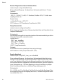
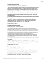
VORSICHT! Beschädigungsgefahr für das IF-Modul!
Das IF-Modul LON darf nur gesteckt oder gezogen werden, wenn die Pumpe
spannungsfrei geschaltet ist.
Pumpe spannungsfrei schalten.
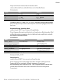
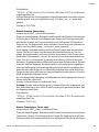
Klemmenkastendeckel nach Lösen der Schrauben abnehmen.
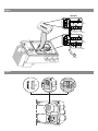
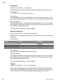
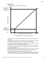
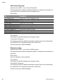
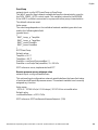
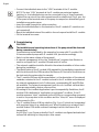
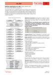
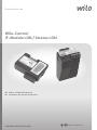
IF-Modul auf die Platinenschnittstelle stecken:
• TOP-E/-ED
Fig. 3a
• Stratos/-D/-Z/-ZD
Fig. 3b
• IP-E/DP-E
Fig. 3c
• IL-E/DL-E
Fig. 3d
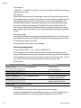
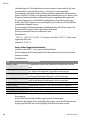
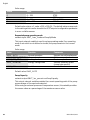
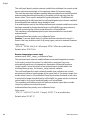
HINWEIS: Damit die in der Einbau- und Betriebsanleitung der Baureihe Stratos
angeführten EMV-Normen eingehalten werden, ist zum Anschluß der Schnittstelle LON ein geschirmtes Kabel zu verwenden.
Um den Schirm dieses Kabels an der Pumpe korrekt aufzulegen, verwenden Sie
die dem IF-Modul Stratos LON beiliegenden metallischen Kabelverschraubungen.
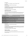
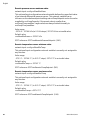
Zur Montage dieser Kabelverschraubung und des entsprechenden Kabels gehen
Sie wie folgt vor (Fig. 4):
Entfernen Sie die Kunststoff-Kabelverschraubung und die zugehörigen Teile
aus dem Kabeleinführung des Regelmoduls (Fig. 4, Pos.4a)
Schrauben Sie die metallische Kabelverschraubung in die Kabeleinführung des
Regelmoduls (Fig. 4, Pos.4b)
Setzen Sie den Kabelaußenmantel des geschirmten Kabels 10...15 mm ab und
klappen Sie den Kabelschirm über den Außenmantel (Fig. 4, Pos.4c).
Führen Sie das Kabel in die Kabelverschraubung ein, bis der umgeklappte Kabelschirm sicher von den Kontaktfedern gehalten wird (Fig. 4, Pos.4d).
Schließen Sie die Einzeladern an den Klemmen „LON“ des IF-Moduls an.
HINWEIS: Die beiden Klemmen „LON“ am IF-Modul sind verdrehsicher, d.h. die
Einzeladern können beliebig an diesen Klemmen angeschlossen werden.
Ziehen Sie die Überwurfmutter der Kabelverschraubung mit einem geeigneten
Werkzeug fest (Fig. 4, Pos.4e)
Bei beengten Platzverhältnissen im Klemmenraum der Pumpe kann auch eine
alternative Montage sinnvoll sein:
Kabel durch Kabelverschraubung führen.
Einzeladern an den Klemmen des IF-Moduls auflegen (IF-Modul ist noch nicht
gesteckt).
Einzeladern des Kabels zu einer Schlaufe legen und IF-Modul montieren.
Klemmenkastendeckel montieren.
Einbau- und Betriebsanleitung Wilo-Control IF-Modul LON / IF-Modul Stratos LON
31
Deutsch
8 Inbetriebnahme
•
•
•
•
•
•
•
•
32
VORSICHT!
Bei der Inbetriebnahme ist die Einbau- und Betriebsanleitung der Pumpe zu
beachten.
Die Inbetriebnahme wird stellvertretend für eine Pumpe mit IF-Modul LON
beschrieben. Bei Vorhandensein mehrerer Pumpen mit IF-Modulen LON ist entsprechend zu verfahren.
Netzspannung der Pumpe(n) einschalten.
Mit einem Netzwerk-Managementtool oder mit dem Programm „Nodeutil.exe“
der Fa. Echelon wird das IF-Modul LON konfiguriert und online geschaltet.
Bei der Installation sind die Bindungen der Netzwerkvariablen mit den Netzwerkvariablen anderer Knoten durchzuführen.
Die für die Installation erforderliche Identifizierung des IF-Moduls LON erfolgt
über den Aufkleber mit dem Code128-Barcode der Neuron-ID. Eine Hälfte des
Aufklebers kann z.B. auf einen Anlagenplan geklebt werden.
Das IF-Modul LON verwendet Selbstdokumentation, d.h. die Beschreibung der
im IF-Modul enthaltenen Netzwerkvariablen ist im IF-Modul gespeichert und
wird von Netzwerk-Managementtools ausgewertet. Daneben sind entsprechende XIF- und XFB-Files verfügbar. Die Unterstützung der NetzwerkManagementtools für nicht LonMark-definierte Datentypen erfolgt über
Device-Resource-Files.
Gemäß den LonMark Application Layer Interoperability Guidelines wird das IFModul LON im Zustand „Application unconfigured“ ausgeliefert. Erhält das IFModul über den LON-Bus ein „Wink“-Kommando, so wird auch in diesem
Zustand ein entsprechendes Kommando zur Pumpe gesendet und an der Pumpe
erscheint das Menü „Id on/off“ für 30 s.
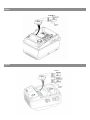
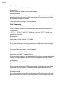
Das IF-Modul Stratos LON weist einen Taster (Fig. 5, Pos.1) auf, der mit einem
spitzen Gegenstand (z.B. Kugelschreiber o.ä.) betätigt werden kann. Beim Betätigen dieses Tasters sendet das IF-Modul Stratos LON eine Netzwerknachricht,
in der die Neuron-ID übertragen wird.
Eine LED (Fig. 5, Pos.2) leuchtet bei einem konfigurierten und online geschalteten IF-Modul nach dem Einschalten der Pumpe oder nach einem Reset kurz auf.
Wenn das IF-Modul LON konfiguriert und online geschaltet ist, erscheint im Display der Pumpe ein Doppelpfeil (Fig. 6, Pos.1), der bestehende Kommunikation
anzeigt. Die lokale Bedienung an der Pumpe mit dem roten Knopf ist gesperrt.
Ausnahmen:
• Einstellungen für die Doppelpumpenfunktionen Spitzenlast- oder Haupt-/
Reservebetrieb
• Durch Drehen des roten Knopfes gelangen Sie in das Menü „Id“. Durch Drücken des roten Knopfes in diesem Menüpunkt wird eine Netzwerknachricht
gesendet, in der die Neuron-ID übertragen wird.
HINWEIS: Bei einer Unterbrechung der Spannungsversorgung der Pumpe arbeitet das IF-Modul LON nicht mehr. Alle Eingangs-Netzwerkvariablen (nvi...) werden beim Wiedereinschalten auf Ihre Startwerte zurückgesetzt.
WILO SE 04/2014
Deutsch
9 Wartung
Wartungs- und Reparaturarbeiten nur durch qualifiziertes Fachpersonal!
WARNUNG! Gefahr durch Stromschlag!
Gefahren durch elektrische Energie sind auszuschließen.
Bei allen Wartungs- und Reparaturarbeiten ist die Pumpe spannungsfrei zu
schalten und gegen unbefugtes Wiedereinschalten zu sichern.
HINWEIS: Das IF-Modul LON besitzt einen lösch- und wiederbeschreibbaren
Programmspeicher, sodass ein späteres Software-Update über den LON-Bus in
diesen Speicher geladen werden kann.
Einbau- und Betriebsanleitung Wilo-Control IF-Modul LON / IF-Modul Stratos LON
33
34
pump_ctrl.sf_voltage_high
Netz-Überspannung
2-Phasenlauf
Blockierung
Leerlauf Motor
Laufr./Rotor schwergängig
Lagerverschleiß
Übertemp. Wicklung
Überlast Motor
Kurz/Erdschluß
Wicklungsschluß
Kontaktfehler / Wicklung offen
Temp.fühler Wicklung offen
Drehzahlsensor defekt
Übertemperatur Modul
Übertemp. Leistungsteil
Zuordnung Modul/Pumpe
Laderelais/PFC defekt
Zwischenkreiselko defekt
Temp.sensor Medium
Ext. Drucksensor defekt
Ext. Schwingungs-sensor defekt
GLT-Timeout
DP-Timeout
E05
E06
E10
E11
E12
E16
E20
E21
E23
E24
E25
E26
E27
E30
E31
E34
E36
E37
E38
E40
E41
E50
E52
pump_ctrl.service_required
pump_ctrl.service_required
pump_ctrl.service_required
pump_ctrl.service_required
nvoMaintenance
gesetzte Bits
pump_ctrl.device_fault
pump_ctrl.device_fault
pump_ctrl.device_fault
pump_ctrl.device_fault
pump_ctrl.device_fault
pump_ctrl.device_fault
pump_ctrl.device_fault
pump_ctrl.device_fault
pump_ctrl.device_fault
pump_ctrl.device_fault
pump_ctrl.service_required
pump_ctrl.service_required
pump_ctrl.service_required
pump_ctrl.service_required
pump_ctrl.service_required
pump_ctrl.service_required
pump_ctrl.service_required
pump_ctrl.service_required
pump_ctrl.device_fault pump_ctrl.service_required
pump_ctrl.device_fault pump_ctrl.service_required
pump_ctrl.device_fault pump_ctrl.service_required
pump_ctrl.device_fault pump_ctrl.service_required
nvoPumpStatus
gesetzte Bits
pump_ctrl.supply_fault
pump_ctrl.device_fault
pump_ctrl.supply_fault
pump_ctrl.device_fault
pump_ctrl.supply_fault
pump_ctrl.device_fault
pump_ctrl.device_fault
pump_ctrl.device_fault
pump_ctrl.device_fault
pump_ctrl.device_fault
pump_ctrl.device_fault
pump_ctrl.device_fault
pump_ctrl.df_elect_failure_nf pump_ctrl.device_fault
pump_ctrl.df_sensor_failure
pump_ctrl.df_elect_failure_nf
pump_ctrl.df_elect_failure_nf
pump_ctrl.df_elect_failure_nf
pump_ctrl.df_elect_failure
pump_ctrl.df_elect_failure
pump_ctrl.df_sensor_failure
pump_ctrl.df_sensor_failure
pump_ctrl.df_sensor_failure
pump_ctrl.df_elect_failure
pump_ctrl.df_motor_failure
pump_ctrl.df_motor_failure
pump_ctrl.df_motor_failure
pump_ctrl.df_motor_failure
pump_ctrl.df_pump_blocked
pump_ctrl.sf_no_fluid
pump_ctrl.df_pump_blocked
pump_ctrl.df_motor_failure
pump_ctrl.df_motor_temp
pump_ctrl.df_motor_failure
pump_ctrl.sf_phase
nvoPumpFault
gesetzte Bits
pump_ctrl.sf_voltage_low
WILO
WILO
LCD-Code Bedeutung
Netz-Unterspannung
E04
nvoStatus
Meldung
electrical_fault
in_alarm
electrical_fault
in_alarm
electrical_fault
in_alarm
in_alarm
in_alarm
in_alarm
in_alarm
in_alarm
electrical_fault
in_alarm
electrical_fault
in_alarm
electrical_fault
in_alarm
electrical_fault
in_alarm
electrical_fault
in_alarm
in_alarm
in_alarm
in_alarm
in_alarm
in_alarm
in_alarm
in_alarm
in_alarm
in_alarm
unable_to_measure
in_alarm
in_alarm
Deutsch
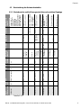
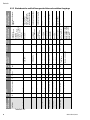
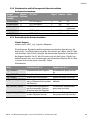
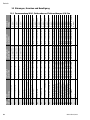
10 Störungen, Ursachen und Beseitigung
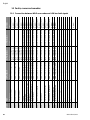
10.1 Zusammenhang WILO-Fehlercodes und Fehlermeldungen LON-Bus
WILO SE 04/2014
Deutsch
HINWEIS: Bei der Fehlerdiagnose sind die Einbau- und Betriebsanleitungen der
entsprechenden Pumpen zu beachten.
Lässt sich die Betriebsstörung der Pumpe/des IF-Moduls nicht beheben,
wenden Sie sich bitte an das Fachhandwerk oder an die nächstgelegene
Wilo-Kundendienststelle oder Vertretung.
11 Entsorgung
Mit der ordnungsgemäßen Entsorgung und durch sachgerechtes Recycling dieses Produktes werden Umweltschäden und eine Gefährdung der persönlichen
Gesundheit vermieden.
1. Zur Entsorgung des Produktes, sowie Teilen davon, die öffentlichen oder
privaten Entsorgungsgesellschaften in Anspruch nehmen.
2. Weitere Informationen zur sachgerechten Entsorgung werden bei der
Stadtverwaltung, dem Entsorgungsamt oder dort, wo das Produkt erworben
wurde, erteilt.
Technische Änderungen vorbehalten!
Einbau- und Betriebsanleitung Wilo-Control IF-Modul LON / IF-Modul Stratos LON
35
English
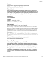
1 General
Installation
and operating instructions
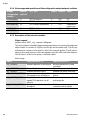
1.1 About this document
The language of the original operating instructions is German. All other
languages of these instructions are translations of the original operating
instructions.
These installation and operating instructions are an integral part of the product.
They must be kept readily available at the place where the product is installed.
Strict adherence to these instructions is a precondition for the proper use and
correct operation of the product.
These installation and operating instructions correspond to the relevant version
of the product and the underlying safety standards valid at the time of going to
print.
These Installation and operating instructions are intended as supplement to
the Installation and operating instructions for the pumps connected to the
LON bus.
2 Safety
These instructions contain important information which must be followed when
installing and operating the pump. These operating instructions must therefore
be read before assembly and commissioning by the installer and the responsible
operator.
2.1 Indication of instructions in the Operating Instructions
Symbols:
General danger symbol
Danger due to electrical voltage
NOTE: ...
Signal words:
DANGER!
Acutely dangerous situation.
Non-observance will result in death or serious injuries.
WARNING!
The user may suffer (serious) injuries. 'Warning' implies that (serious) injury
to persons is likely if this information is disregarded.
36
WILO SE 04/2014
English
CAUTION!
There is a risk of damaging the pump/unit. 'Caution' implies that damage to
the product is possible if this information is disregarded.
NOTE: Useful information on using the product. It also draws attention to
potential problems.
2.2 Safety instructions for inspection and installation work
The safety instructions in the installation and operating instructions for the
entire unit should be observed for all work on the pump(s).
WARNING! Danger from electric shock
Any hazards from electrical current should be ruled out.
Work on the unit/pump(s) may only be carried at a mechanical standstill,
in electrically isolated condition and with appropriate tools.
3 Transport and interim storage
Inspect the pump/system for transport damage immediately upon arrival. Any
transport damage found must be reported to the carrier within the prescribed
periods.
CAUTION! Risk of damage to the IF-module!
Risk of damage due to improper handling during transport and storage.
• The IF-modules should be protected against humidity, frost and mechanical
damage during transport and temporary storage.
• They must not be exposed to temperatures outside the range of - 10 °C to
+ 70 °C.
4 Intended use
Wilo-Control IF-module LON, IF-module Stratos LON
The IF-module LON is used to connect electronically controlled glandless or glanded
pumps to a LON. The pump can be preset with setpoints, operating modes and data from
external sensors, and current operating data and fault signals can be transferred from the
pump via the LON bus.
At the same time the IF-module LON allows two pumps to be connected to form a
double pump via an additional DP interface. This interface is a separate device. It is not
a LON-based interface. That is why the LON bus for the double pump interface is not put
under strain and the slave pump can be equipped with an inexpensive IF-module PLR.
Installation and operating instructions Wilo-Control IF-module LON / IF-module Stratos LON
37
English
Connectable pump types
Glandless pumps
Glanded pumps
• Wilo-TOP-E with IF-module LON
• Wilo-TOP-ED with IF-module LON
and IF-module PLR
• Wilo-Stratos with IF-module Stratos LON
• Wilo-Stratos-D with IF-module Stratos
LON and IF-module Stratos PLR
• Wilo-Stratos-Z with IF-module Stratos
LON
• Wilo-Stratos-ZD with IF-module Stratos
LON and IF-module Stratos PLR
Table 4.1
• Wilo-VeroLine-IP-E with IF-module LON
• Wilo-VeroTwin-DP-E with IF-module
LON
• Wilo-CronoLine-IL-E with IF-module
LON
• Wilo-CronoTwin-DL-E with IF-module
LON and IF-module PLR
5 Product information
5.1 Type key
Example: Wilo-Control IF-module LON
Control
5.2
IF-module LON
IF-module Stratos LON
Technical specifications
Processor:
Memory:
Transceiver:
Clock:
Firmware:
Power supply:
Current input:
Ambient temperature:
Bus cable:
Max. bus cable length:
Program ID (software):
38
Series designation
Type designation:
TMPN3150B1AF or CY7C53150
32 KB flash
FTT 10A
10 MHz
Version 7
5 V= and 15 V= via the pump
Approx. 30 mA
0 °C – 40 °C
JY(St) Y 2 x 2 x 0.8
• 900 m with bus topology with max. 3 m stub length
• 450 m with free topology, with max. 250 m between
2 inter-communicating nodes
9F:FF:CC:51:14:06:04:04
WILO SE 04/2014
English
5.3 Standards
The IF-module LON complies with the following standards:
• LonMark Application Layer Interoperability Guidelines version 3.2
• LonMark Layers 1-6 Interoperability Guidelines version 3.2
• LonMark node object 0000_20
• LonMark pump controller object 8120_10
• LonMark Resource Files version 13.00
The entire documentation can be found at www.wilo.de (- Produkte (Products),
- Wilo Schaltgeräte (Wilo switching devices), - LonMark Functional Profile ...).
5.4 Scope of delivery
• IF-module LON or IF-module Stratos LON
• PG 7 metallic cable connection
• PG 9 metallic cable connection
• Installation and operating instructions
5.4.1 Delivery condition
According to the LonMark Application Layer Interoperability Guidelines, the IFmodule LON is delivered in “application unconfigured” condition.
In this condition, the IF-module LON can be addressed via the LON bus,
but the application which normally establishes the communication with
the pump is not yet in operation. There is therefore no activity yet after
connecting the IF-module LON and switching on the power supply of the pump.
6 Description and function
6.1 Description of the objects
Two objects, the node object and pump object, are implemented in the IFmodule LON. The node object is used to control individual objects within the
node; errors which occur in the individual objects are also indicated centrally
here.
Fig. 1a shows the node object with the corresponding network variables,
Fig. 1b shows the pump controller object with the corresponding network
variables.
NOTE:
• Double pumps should always be equipped with the integrated double pump
management.
• At double pumps, the IF-module LON is connected to the master.
• If the integrated double pump management is not used for double pumps,
the two drives should be treated as two separate individual pumps. In this case,
two LON IF modules are necessary.
• The control functions apply to the double pump as entire unit.
Installation and operating instructions Wilo-Control IF-module LON / IF-module Stratos LON
39
40
O
O
nviOvdPress
nviRemotePress
nviRemoteTemp O
O
nviOvdSpeed
SNVT_switch
nviPumpOvdStop O
SNVT_temp_p
SNVT_press
SNVT_press
1
1
1
SNVT_lev_percent 1
1
SNVT_hvac_mode 1
nviPumpOpMode M
1
SNVT_obj_request 0
SNVT_switch
M
no
no
no
no
no
no
12 yes
10 yes
8
7
6
2
1
1
-
-273.17
... +327.66 °C
0.01°C
0.1 kPa
-3276.8
... +3276.6 kPa
0x7FFF
0x7FFF
0x7FFF
0x7FFF
0x7FFF
0x7FFF
0x7FFF
0x7FFF
Eff. resol.: 0.1°C
Eff. resol.: 0.981 kPa
-273.1 – 327.6 °C
0 - 100%
Eff. resolution: 0.5%
Range depends on
pump type.
Eff. resol.: 0.981 kPa
0 – 3276.6 kPa
HVAC_AUTO 0xFF
HVAC_AUTO
(HVAC_NUL) HVAC_MRNG_WRMUP
HVAC_PRE_COOL
HVAC_ECONOMY
.state: 0xFF .state: 0xFF .state: 0 – 1
.value: 0xFF
.value: 0.0 – 100.0%
Resolution Default value Invalid data Data range and
effective
resolution WILO
.object_id: 0 – 1
.object_request:
RQ_NORMAL
RQ_DISABLED
RQ_ENABLE
RQ_UPDATE_STATUS
RQ_REPORT_MASK
RQ_CLEAR_STATUS
SCPTsetpoint .state: 0 – 1
.value: 0.0 – 100.0%
.state: 0 – 1
.value: 0.0
... +100.0%
0.005 %
-163.84
... +163.83 %
0.1 kPa
-3276.8
... +3276.6 kPa
(hvac_t)
.state: 0 – 1
.value: 0.0
– 100.0%
enum 0 ... 17
-
Object No. Receive Data range
heartbeat and units
nviPumpSetpoint M
nviRequest
Input
Mand. / NVT
network variable opt.
English
6.2 Description of the network variables
6.2.1 Value ranges and resolutions of the input network variables
Table 6.2.1
WILO SE 04/2014
O
O
O
O
M
nvoPowerKilo
nvoRuntime
nvoSpeed
nvoFluidTemp
nvoControlMode
Installation and operating instructions Wilo-Control IF-module LON / IF-module Stratos LON
1
1
1
1
1
1
1
1
1
yes
5
yes
21 no
16 no
18 no
23 no
22 no
24 no
15 no
14 no
3
Obj No. Send
heartbt /
Ack
0 2 yes
SNVT_dev_c_mode 1
SNVT_temp_p
SNVT_rpm
SNVT_time_hour
SNVT_power_kilo
SNVT_power
O
nvo Power
SNVT_flow_p
SNVT_elec_kWh
O
nvoFlow
SNVT_press
SNVT_lev_percent
nvoEnergyConsum O
O
nvoPressure
nvoPumpCapacity M
M
nvoStatus
SNVT_obj_status
Mand. / NVT
opt.
Output
network variable
yes
yes
yes
yes
yes
yes
yes
yes
yes
yes
1 rpm
1h
0.1 kW
0.1 W
-273.17
0.01 °C
– 327.66 °C
ENUM 0 – 29
(device_c_mode_t)
0 – 65535 rpm
0 – 65535 h
0 – 6553.5 kW
0 – 6553.5 W
1 kWh
0.01 m3/h
0 – 655.34 m3/h
0 – 65535 kWh
0.1 kPa
0.005 %
0x7FFF Range depends on
pump type
Res.: 0.981 kPa
0xFFFF Range depends on
pump type
Res.: 0.1 m3/h
0 – 65535 kWh
Res.: 1 kWh
0 – 6553W
Res.: min. 1 W
0 – 65.5 kW
Res.: 0.1 kW
0 – 65535 h
Res.: 10 h
0 – 65535 rpm
Res.: min. 1 rpm
0x7FFF -50 °C – 205°C
Res.: min. 0.1 °C
0xFF DCM_SPEED_CONST
DCM_PRESS_CONST
DCM_PRESS_COMP
DCM_PRESS_AUTO
DCM_NUL
invalid_id
invalid_request
disabled
electrical_fault
unable_to_measure
manual_control
in_alarm
0x7FFF 0 – 100.0%
Res: 0.2%
-
Immediately
2 % of
nroPumpChar.speedMax
5 °C
10 h
10 % of max. power
10 % of max. power
1 kWh
5 % of
nroPumpChar.flowMax
5 % of
nroPumpChar.pressMax
or 2 % of
nroPumpChar.speedMax
resp., control mode
changes
5 % of
nroPumpChar.pressMax
Send upon nviRequest:
update
Resolution Invalid Range and effective Send when value
data
resolution WILO
changes more than
-3276.8
– 3276.6 kPa
-163.84
– 163.83 %
Min. Data range
send and units
time
yes
English
6.2.2 Value ranges and resolutions of the output network variables
Table 6.2.2
41
42
1
M
SNVT_switch
SNVT_hvac_mode 1
O
O
SNVT_dev_status 1
O
O
yes
17 no
4
13 yes
Obj No. Send
heartbt /
Ack
SNVT_dev_maint 1 20 no
SNVT_dev_fault 1 19 no
Mand. / NVT
opt.
yes
yes
yes
Min.
send
time
yes
yes
-
-
-
Range and effective
resolution WILO
service_required
sf_voltage_low
sf_voltage_high
sf_phase
sf_no_fluid
df_motor_temp
df_motor_failure
df_pump_blocked
df_elect_temp
df_elect_failure_nf
df_elect_failure
df_sensor_failure
device_fault
supply_fault
speed_low
speed_high
setpt_out_of_range
local_control
running
remote_press
remote_temp
0xFF
HVAC_AUTO
HVAC_MRNG_WRMUP
HVAC_PRE_COOL
HVAC_ECONOMY
HVAC_NUL
.state: 0xFF .state: 0 – 1
.value: 0.0%, 100.0%, 0xFF
-
Resolution Invalid
data
.state: 0 – 1
.value: 0.0–100.0%,
ENUM 0 – 17
(hvac_t)
Bit set
Bit set
Bit set
Data range
and units
Immediately
Immediately
Immediately
Immediately
Immediately
Send when value
changes more than
English
Table 6.2.2, continuation
WILO SE 04/2014
SCPTmaxSendTime
SCPTminSendTime
M
O
O
O
O
O
O
U
O
nciSndHrtBt
nciMinOutTm
nciControlMode
nciRemMinPress
nciRemMaxPress
nciRemMinTemp
nciRemMaxTemp
nciPressTemp
nciSetpPreset
1
1
1
0
1
0
Installation and operating instructions Wilo-Control IF-module LON / IF-module Stratos LON
SCPTsetpoint
UCPTPressTemp
SCPTmaxRemoteTempSetpoint
SCPTminRemoteTempSetpoint
1
1
1
1
SCPTmaxRemotePressureSetpoint 1
213
244
243
240
239
238
52
49
17
48
22
0–0d17h59m59s
Eff. res: 1 s
0–6553 s
Eff. res: 1 s
0–6553s
Eff. res: 1 s
0–6553 s
Eff. res: 1 s
DCM_SPEED_CONST
DCM_PRESS_CONST
DCM_PRESS_COMP
DCM_PRESS_AUTO
0 – 3276.7 kPa
Eff. res: 0.981 kPa
0 – 3276.7 kPa
Eff. res: 0.981 kPa
-273.1 – 327.6 °C
Eff. res: 0.1°C
-273.1 – 327.6 °C
Eff. res: 0.1°C
.TempMin, .TempMax:
0 – 110 °C
Eff. res: 0.1°C
.PressMin, .PressMax:
0 – 3276.7 kPa
Eff. res: 0.981 kPa
.state: 0–1
.value: 0–255
Object Number Data range and effective
resolution WILO
SCPTminRemotePressureSetpoint 1
SCPTdeviceControlMode
SCPTlocation
SCPTmaxRcvTime
O
O
nciLocation
nciRcvHrtBt
Input configuration variable Mandatory / CPT / NVT
optional /
user
nciMaxStsSendT
O
SCPTmaxSndT
nvoPumpOverride
nvoEffOpMode
nvoPumpStatus
nvoMaintenance
nvoPumpFault
Output
network variable
English
Table 6.2.2, continuation
6.2.3 Value ranges and resolutions of the configuration input network variables
Table 6.2.3
43
English
6.2.4 Value ranges and resolutions of the configuration output network variables
Output
configuration
variable
Mandat./
optional
CPT / NVT
Object Number Value
nciDevMajVer
nciDevMinVer
nroPumpChar
O
O
M
SCPTdevMajVer
SCPTdevMinVer
SCPTpumpCharacteristic
0
0
1
165
166
233
nciObjMajVer
nciObjMinVer
O
O
SCPTobjMajVer
SCPTobjMinVer
1
1
167
168
02
00
Depends on
pump type
02
00
6.2.5 Description of the network variables
Object request
network input SNVT_obj_request nviRequest
This input network variable triggers various operations concerning the node and
object status. It consists of 2 bytes, the ID byte and the value byte. The ID byte
indicates the number of the object to which the request applies. The ID value 0
refers to the node object; in this case requests may also affect all other objects.
The ID value 1 refers to the pump-controller object.
Value range
Value
Function with ID = 0
RQ_NORMAL
Normal operation of all objects Normal operation of pump
controller
Stops all objects
Stops the pump controller
Enables the node object
Enables the pump controller
Updates the node object status Updates the pump controller
(OR operation for all objects)
status
Supported node object status Supported pump controller
signals (OR operation for all
status signals
objects)
Deletes certain status signals in Deletes certain pump
all objects
controller status signals
RQ_DISABLED
RQ_ENABLE
RQ_UPDATE_STATUS
RQ_REPORT_MASK
RQ_CLEAR_STATUS
44
Function with ID = 1
WILO SE 04/2014
English
Object status
network output SNVT_obj_status nvoStatus
This output network variable provides status information on the individual
objects. The information is bit-coded. All bits are deleted after a reset.
Value range
Bit
Function
invalid_id
invalid_request
disabled
electrical_fault
unable_to_measure
comm_failure
manual_control
A non-existent object was addressed.
An unknown request was sent.
The object in concern is switched off.
The pump controller object indicates an electrical error.
The pump controller object cannot communicate with the pump.
For the node object only
The pump controller object is disabled for controlling by the
hardware settings at the pump (ext. off, ext. min, IR monitor)
The pump controller object indicates an error.
Indicates that nvoStatus contains the status mask, i.e. the list of all
supported bits, due to a preceding RQ_REPORT_MASK request.
in_alarm
report_mask
Installation and operating instructions Wilo-Control IF-module LON / IF-module Stratos LON
45
English
Maximum status send time
network input config SNVT_elapsed_tm nciMaxStsSendT
This optional input configuration network variable defines a clock at which the
object statuses are automatically sent. The status of the node object and
pump-controller object are sent alternately.
Value range
0d0h0m0s0ms – 0d17h59m59s999ms (in 1 s steps). The value 0d0h0m0s0ms
switches off automatic sending.
Default value: 0d0h0m0s0ms (automatic sending switched off)
SCPT reference: SCPTmaxSendT (22)
Device major version
network output config unsigned short nciDevMajVer
This optional output configuration network variable provides the high byte of
the module version.
SCPT reference: SCPTdevMajVer (165)
Device minor version
network output config unsigned short nciDevMinVer
This optional output configuration network variable provides the low byte of
the module version.
SCPT reference: SCPTdevMinVer (166)
Location label
network input config SNVT_str_asc nciLocation
This optional input configuration network variable can be used to save
information about the installation location of the pump which goes beyond the
information string stored in the Neuron chip, which only consists of 6 Byte.
Value range
Optional NUL-terminated ASCII string of max. 31 bytes length (incl. NUL)
Default value
ASCII string which only consists of NUL (“\0”)
SCPT reference: SCPT_location (17)
46
WILO SE 04/2014
English
Pump setpoint
network input SNVT_switch nviPumpSetpoint
Actual setpoint [%]
Setpoint upper limit
(depending on
manfacturer, pump
and control mode)
Setpoint lower limit
(depending on
manufacturer, pump
and control mode)
STOP
X
Pump Setpoint nviPumpSetpoint [%]
100%
X = ( Setpoint lower limit / setpoint upper limit ) * 100%
This input network variable is used to switch the pump on and off and specify
a setpoint.
The network variable consists of a status byte in which the switch-on condition
is transmitted and a value byte in which the setpoint is transmitted.
If a status byte of 0 is set, the pump is switched off. If a status byte of 1 is set,
the switch-on condition depends on the value byte.
If a setpoint of 0% is preset, the pump is switched off. If a setpoint greater than
0% is preset, the pump is switched on if the status byte is 1. The setpoint can
be changed in steps of 0.5%.
If setpoints greater than the upper setpoint limit value are set, they are reduced
to the upper setpoint limit value. Accordingly setpoints below the lower
setpoint limit value are raised to the lower setpoint limit value.
The upper and lower setpoint limit values may change if the pump is operated with
an external sensor (see nviRemotePress, nciRemMinPress and nciRemMaxPress).
Installation and operating instructions Wilo-Control IF-module LON / IF-module Stratos LON
47
English
Value range
Status
Value
Function
0
1
1
1
0 – 255
0
1 – 200
201 – 255
STOP
STOP
0.5 – 100.0%
100.0%
Default value: status = 1, value = 200 = 100.0%. The default value corresponds
to the setting which can be stored in the SCPTsetpoint configuration parameter
in a non-volatile manner.
Requested pump operating mode
network input SNVT_hvac_mode nviPumpOpMode
This input network variable is used to set an operating mode. If an operating
mode is set which is not defined or invalid, the pump remains in the current
mode.
Value range
Value
Function
Comments
HVAC_AUTO
HVAC_MRNG_WRMUP
HVAC_PRE_COOL
HVAC_ECONOMY
Normal operation
Warm-up mode
Cooling mode
Energy-saving mode
Setpoint via nviPumpSetpoint
Maximum speed
Maximum speed
Setback operation speed
(pump type specific)
HVAC_NUL
Invalid
Default value: HVAC_AUTO
Pump Capacity
network output SNVT_lev_percent nvoPumpCapacity
This output network variable provides the current operating point of the pump
as percentage of the maximum setpoint.
When using an external pressure or temperature sensor, this variable provides
the sensor value as a percentage of the maximum sensor value.
48
WILO SE 04/2014
English
Value range
-163.840% – 163.830% (in 0,02% steps). 163.835% is an invalid value.
Transmission
This value is transmitted automatically if it deviates from the value transmitted
last by more than 5% of the value in nroPumpChar.pressMax (with differential
pressure control) or 2% of the value in nroPumpChar.speedMax (with speed
controller). Furthermore, this value is regularly transmitted if the nciSndHrtBt
configuration input was described with a valid clock. This value is also
transmitted if the control mode has been changed by overriding settings or the
connection of an external sensor.
Transmission frequency
The minimum network variable transmission interval can be set by describing
the nciMinOutTm configuration input with a valid clock.
Preset service type: acknowledged
Effective operating mode
network output SNVT_hvac_mode nvoEffOpMode
This output network variable provides the current operating mode of the pump.
This value corresponds to the setting in the nviPumpOpMode input network
variable, provided a different operating mode has not been forced by local
settings at the pump (ext. off, ext. min or IR monitor).
Value range
Value
Function
Comments
HVAC_AUTO
HVAC_MRNG_WRMUP
HVAC_PRE_COOL
HVAC_ECONOMY
Normal operation
Warm-up mode
Cooling mode
Energy-saving mode
HVAC_OFF
Offline mode
Setpoint via nviPumpSetpoint
Maximum speed
Maximum speed
Setback operation speed
(pump type specific)
Ext. off or manual operation mode
via IR monitor
HVAC_NUL
Invalid
Transmission
This value is automatically transmitted whenever a change is made.
Furthermore, this value is transmitted regularly if the nciSndHrtBt configuration
input was described with a valid clock.
Transmission frequency
The minimum network variable transmission interval can be set by describing
the nciMinOutTm configuration input with a valid clock.
Preset service type: acknowledged
Installation and operating instructions Wilo-Control IF-module LON / IF-module Stratos LON
49
English
Effective device control mode
network output SNVT_dev_c_mode nvoControlMode
This output network variable provides the current control mode of the pump.
Value range
Value
Function
DCM_SPEED_CONST
DCM_PRESS_CONST
DCM_PRESS_COMP
DCM_PRESS_AUTO
Constant speed mode
Constant pressure mode
Compensated pressure mode
Temperature-dependent differential pressure
Transmission
This value is automatically transmitted whenever a change is made.
Furthermore, this value is transmitted regularly if the nciSndHrtBt configuration
input was described with a valid clock.
Transmission frequency
The minimum network variable transmission interval can be set by describing
the nciMinOutTm configuration input with a valid clock.
Preset service type: acknowledged
Pump override stop command
network input SNVT_switch nviPumpOvdStop
This optional input network variable provides an overriding switch-on/switchoff function and is intended for maintenance work, for example. The network
variable consists of a status byte and a value byte.
The “OVDSTOP” setting has priority over the setpoint set in nviPumpSetpoint
and the overriding setpoints set in nviOvdSpeed and nviOvdPress.
An overriding setting is indicated in the nvoPumpOverride output network variable.
Value range
Status
Value
Function
0
1
1
255
0 – 255
0
1 – 255
0 – 255
NORMAL
NORMAL
OVDSTOP
Invalid (NORMAL)
Default value: status = 255, value = 255
50
WILO SE 04/2014
English
Override setpoint for speed
network input SNVT_lev_percent nviOvdSpeed
This optional input network variable is used for the overriding setting of a speed
setpoint, e.g. for maintenance work. The value is set as a percentage of the
maximum value of the pump. If a valid range is received, the setpoint set via
nviPumpSetpoint or nviOvdPress is overwritten and speed controller mode
automatically set.
The pump is reset to normal condition by an invalid value in all overriding
nviOvdSpeed and nviOvdPress setpoint settings and a “Normal” setting via
nviPumpOvdStop.
An overriding setting is indicated in the nvoPumpOverride output network variable.
Value range
-163.84% – 163.83% (in 0.005% steps). 163.835% is an invalid value.
Values lower than 0% or higher than 100% are limited accordingly and
nvoPumpStatus.pump_ctrl.setpt_out_of_range is set.
Default value: 163.835%
Override setpoint for pressure
network input SNVT_press nviOvdPress
This optional input network variable is used for the overriding setting of
a differential pressure setpoint, e.g. for maintenance work. The value is set as
a percentage of the maximum value of the pump. If a valid range is received,
the setpoint set via nviPumpSetpoint or nviOvdSpeed is overwritten and the
constant differential pressure control mode is automatically set.
The pump is reset to normal condition by an invalid value in all overriding
nviOvdSpeed and nviOvdPress setpoint settings and a “Normal” setting via
nviPumpOvdStop.
An overriding setting is indicated in the nvoPumpOverride output network variable.
Value range
-3276.8 – 3276.6 kPa (in 0.1 kPa steps). 3276.7 kPa is an invalid value.
Values outside the valid range for the respective pump are limited accordingly
and nvoPumpStatus.pump_ctrl.setpt_out_of_range is set.
Default value: 3276.7 kPa
Remote pressure sensor input
network input SNVT_press nviRemotePress
This optional input network variable allows an external differential pressure
sensor to be used to control the pump. If a valid value is received, the pump
automatically switches to constant differential pressure control mode.
Control by means of an external sensor is indicated in the
nvoPumpStatus.pump_ctrl.remote_press network variable.
Installation and operating instructions Wilo-Control IF-module LON / IF-module Stratos LON
51
English
The nvoPumpCapacity output network variable then indicates the current actual
sensor value as a percentage of the maximum value of the sensor range.
The nvoPressure output network variable always provides the actual differential
pressure value determined internally by the pump, which may vary from the
sensor value. This is used to analyse the system behaviour. The differential
pressure setpoint is still preset via the nviPumpSetpoint input network variable if
the nviRemotePress network input variable is used.
If an invalid value is sent to the nviRemotePress input network variable or no value
has been received for longer than defined in nciRcvHrtBt, the pump returns to
internal control and the control mode defined in nciControlMode.
The overriding nviOvdSpeed setpoint input also overrides the control with
external sensor.
nviRemotePress has priority over nviRemoteTemp.
Caution: To ensure stable control, nviRemotePress must be sent every 3 s.
Even in this case, stable control of all pump types cannot be ensured however.
Value range
-3276.8 – 3276.6 kPa (in 0.1 kPa steps). 3276.7 kPa is an invalid value.
Default value: 3276.7 kPa.
Remote temperature sensor input
network input SNVT_temp_p nviRemoteTemp
This optional input network variable allows an external temperature sensor
to be used to control the pump. If a valid value is received, the pump
automatically switches to temperature-dependent differential pressure
control mode. Control by means of an external sensor is indicated in the
nvoPumpStatus.pump_ctrl.remote_temp network variable.
The nvoPumpCapacity output network variable then indicates the current
actual sensor value as a percentage of the upper limit of the sensor range. If an
invalid value is sent to the nviRemoteTemp input network variable or no value
is received for longer than defined in nciRcvHrtBt, the pump returns to internal
control and to the control mode defined in nciControlMode.
The overriding nviOvdSpeed and nviOvdPress setpoint inputs also override
control by means of an external sensor.
nviRemotePress has priority over nviRemoteTemp.
Value range
-273.17 ... +327.66 °C (in 0.01 °C steps). 327.67 °C is an invalid value.
Default value: 327.67 °C.
52
WILO SE 04/2014
English
Pump status diagnostic information
network output SNVT_dev_status nvoPumpStatus
This output network variable provides bit-coded information about the pump
status.
Value range
Bit
Description
device_fault
supply_fault
Pump error (see nvoPumpFault for detailed information)
Supply error (mains voltage, phase missing, dry run, etc.
See nvoPumpFault for detailed information)
Lower control limit (pump is running at minimum speed, which
is why the required operating point cannot be achieved)
Upper control limit (pump is running at maximum speed, which
is why the required operating point cannot be achieved)
Setpoint exceeded/fallen short of
Local operation (by ext. off, ext. min or IR monitor)
Pump is running
Control by means of external pressure sensor
Control by means of external temperature sensor
speed_low
speed_high
setpt_out_of_range
local_control
running
remote_press
remote_temp
Transmission
This value is automatically transmitted whenever a change is made.
Furthermore, this value is transmitted regularly if the nciSndHrtBt configuration
input was described with a valid clock.
Transmission frequency
The minimum network variable transmission interval can be set by describing
the nciMinOutTm configuration input with a valid clock.
Preset service type: acknowledged
Pump Pressure
network output SNVT_press nvoPressure
This optional output network variable provides the differential pressure
between the pump flanges determined internally by the pump.
Value range
0 – 3276.6 kPa ( in 0.1 kPa steps). 3276.7 kPa is an invalid value.
Transmission
This value is automatically transmitted if it deviates from the value transmitted
last by more than 5% of the value in nroPumpChar.pressMax.
Installation and operating instructions Wilo-Control IF-module LON / IF-module Stratos LON
53
English
Transmission frequency
The minimum network variable transmission interval can be set by describing
the nciMinOutTm configuration input with a valid clock.
Preset service type: unacknowledged
Pump flow
network output SNVT_flow_p nvoFlow
This optional output network variable provides the flow rate determined by
the pump.
Value range
0 - 655.34 m3/h (in 0.01 m3/h steps). 655.35 m3/h is an invalid value.
Transmission
This value is automatically transmitted if it deviates from the value transmitted
last by more than 5% of the value in nroPumpChar.flowMax.
Transmission frequency
The minimum network variable transmission interval can be set by describing
the nciMinOutTm configuration input with a valid clock.
Preset service type: unacknowledged
Pump speed
network output SNVT_rpm nvoSpeed
This optional output network variable provides the speed of the pump.
Value range
0 – 65535 rpm (in 1 rpm steps).
Transmission
This value is automatically transmitted if it deviates from the value transmitted
last by more than 5% of the value in nroPumpChar.speedMax.
Transmission frequency
The minimum network variable transmission interval can be set by describing
the nciMinOutTm configuration input with a valid clock.
Preset service type: unacknowledged
54
WILO SE 04/2014
English
Pump override active
network output SNVT_switch nvoPumpOverride
This optional output network variable provides the status of the overriding
settings.
Value range
Status
Value
Function
0
1
255
0
200
0 – 255
NORMAL
OVERRIDE
Invalid
Transmission
This value is transmitted whenever a change is made.
Transmission frequency
The minimum network variable transmission interval can be set by describing
the nciMinOutTm configuration input with a valid clock.
Preset service type: unacknowledged
Runtime
network output SNVT_time_hour nvoRuntime
This optional output network variable provides the operating hours of the
pump, or with double pumps, the time during which at least one pump was
running. The counter is reset to 0 h after 65535 h.
Value range
0 – 65535 h (in 10 h steps), (max. 2730 d or 7.48 a).
Transmission
This value is transmitted whenever a change is made.
Transmission frequency
The minimum network variable transmission interval can be set by describing
the nciMinOutTm configuration input with a valid clock.
Preset service type: unacknowledged
Installation and operating instructions Wilo-Control IF-module LON / IF-module Stratos LON
55
English
Fault states of the pump
network output SNVT_dev_fault nvoPumpFault
This optional output network variable provides bit-coded error information of
the pump. Errors can be device errors or supply errors.
Value range
Bit
Description
sf_voltage_low
sf_voltage_high
sf_phase
sf_no_fluid
df_motor_temp
df_motor_failure
df_pump_blocked
df_elect_failure_nf
df_elect_failure
df_sensor_failure
Supply error, mains voltage too low
Supply error, mains voltage too high
Supply error, phase missing
Supply error, dry running
Device error, excess motor temperature
Device error, motor defective
Device error, pump blocked
Device error, electronic error
Device error, electronics defective
Device error, sensor defective
Transmission
This value is transmitted whenever a change is made.
Transmission frequency
The minimum network variable transmission interval can be set by describing
the nciMinOutTm configuration input with a valid clock.
Preset service type: unacknowledged
Maintenance states
network output SNVT_dev_maint nvoMaintenance
This optional output network variable provides bit-coded service information of
the pump.
Value range
service_required = service required
Transmission
This value is transmitted whenever a change is made.
Transmission frequency
The minimum network variable transmission interval can be set by describing
the nciMinOutTm configuration input with a valid clock.
Preset service type: unacknowledged
56
WILO SE 04/2014
English
Fluid temperature
network output SNVT_temp_p nvoFluidTemp
This optional output network variable provides the fluid temperature.
Value range
-273.17 – 327.66 °C (in 0.01 °C steps). 327.67 °C is an invalid value.
Transmission
This value is automatically transmitted if it deviates from the value transmitted
last by more than 5 °C.
Transmission frequency
The minimum network variable transmission interval can be set by describing
the nciMinOutTm configuration input with a valid clock.
Preset service type: unacknowledged
Power consumption in watts
network output SNVT_power nvoPower
This optional output network variable provides the power consumption of the
pump or, in the event of double pumps, the total power output of the master
and slave.
Value range
0 – 6553,5 W (in 0,1 W steps).
Transmission
This value is automatically transmitted if it deviates from the value transmitted
last by more than 10% of the maximum power consumption of the pump.
Transmission frequency
The minimum network variable transmission interval can be set by describing
the nciMinOutTm configuration input with a valid clock.
Preset service type: unacknowledged
Power consumption in kW
network output SNVT_power_kilo nvoPowerKilo
This optional output network variable provides the power consumption of the
pump or, in the event of double pumps, the total power output of the master
and slave.
Value range
0 – 6553.5 kW (in 0.1 kW steps).
Transmission
This value is automatically transmitted if it deviates from the value transmitted
last by more than 10% of the maximum power consumption of the pump.
Installation and operating instructions Wilo-Control IF-module LON / IF-module Stratos LON
57
English
Transmission frequency
The minimum network variable transmission interval can be set by describing
the nciMinOutTm configuration input with a valid clock.
Preset service type: unacknowledged
Energy consumption
network output SNVT_elec_kwh nvoEnergyConsum
This optional output network variable provides the energy consumption of the
pump or, in the case of double pumps, the total energy consumption of the
master and slave. The counter is reset to 0 kWh after 65535 kWh.
Value range
0 – 65535 kWh (in 1 kWh steps).
Transmission
This value is transmitted whenever a change is made.
Transmission frequency
The minimum network variable transmission interval can be set by describing
the nciMinOutTm configuration input with a valid clock.
Preset service type: unacknowledged
Control mode for normal operation
network input config SNVT_dev_c_mode nciControlMode
This optional input network variable defines the control mode for normal operation
of the pump if no external sensors are used and no overriding settings are active.
Value range
Value
Function
DCM_SPEED_CONST
DCM_PRESS_CONST
DCM_PRESS_COMP
DCM_PRESS_AUTO
Constant speed mode
Constant pressure mode
Compensated pressure mode
Temperature-dependent differential pressure
Default value
DCM_PRESS_COMP
SCPT reference: SCPTdeviceControlMode (238)
58
WILO SE 04/2014
English
PressTemp
network input config UCPTpressTemp nciPressTemp
This WILO-specific input network variable defines the characteristic curve for
the DCM_PRESS_AUTO control mode. This variable is stored in the EEPROM.
If the LON IF-module is connected to a pump with other pump characteristics .
The default values are reset.
Value range
The value range depends on the individual network variable types which are
used in the following data field:
typedef struct
{
SNVT_temp_p TempMin
SNVT_temp_p TempMax
SNVT_press PressMin
SNVT_press PressMax
}
UCPTPressTemp
Default values
TempMin = 50 °C
TempMax = 90 °C
PressMin = nroPumpChar.pressMax / 2
PressMax = nroPumpChar.pressMax / 2 + 9.8 kPa
SCPT reference: none; implemented as UCPT
Remote pressure sensor minimum value
network input config nciRemMinPress
This optional input configuration network variable defines the lower limit value
of an external differential pressure sensor. This network variable is not currently
assigned any function.
Value range
-3276.8 – 3276.6 kPa (in 0.1 kPa steps). 3276.7 kPa is an invalid value.
Default value
<nciRemMinPress> = 3276.7 kPa
SCPT reference: SCPTminRemotePressureSetpoint (239)
Installation and operating instructions Wilo-Control IF-module LON / IF-module Stratos LON
59
English
Remote pressure sensor maximum value
network input config nciRemMaxPress
This optional input configuration network variable defines the upper limit value
of an external differential pressure sensor. This network variable has an
influence on the relative setpoint settings via nviPumpSetpoint and on the value
supplied by nvoPumpCapacity if the preset value is smaller than
nroPumpChar.pressMax. Larger values are always limited internally to
nroPumpChar.pressMax.
Value range
-3276.8 – 3276.6 kPa (in 0.1 kPa steps). 3276.7 kPa is an invalid value.
Default value
<nciRemMaxPress> = 3276.7 kPa
SCPT reference: SCPTmaxRemotePressureSetpoint (240)
Remote temperature sensor minimum value
network input config nciRemMinTemp
This optional input configuration network variable is currently not assigned to
any function.
Value range
-273.17 – 327.66 °C (in 0.01 °C steps). 327.67 °C is an invalid value.
Default value
<nciRemMinTemp> = 327.67 °C
SCPT reference: SCPTminRemoteTempSetpoint (243)
Remote temperature sensor maximum value
network input config nciRemMaxTemp
This optional input configuration network variable is currently not assigned to
any function.
Value range
-273.17 – 327.66 °C (in 0.01 °C steps). 327.67 °C is an invalid value.
Default value
<nciRemMaxTemp> = 327.67 °C
SCPT reference: SCPTmaxRemoteTempSetpoint (244)
60
WILO SE 04/2014
English
Pump Characteristic
network output config nroPumpChar
This output configuration network variable provides a data field with the pump
characteristics.
Value range
The value range depends on the individual network variable types which are
used in the following data field:
typedef struct {
SNVT_rpm speedMax;
SNVT_press pressMax;
SNVT_flow_p flowMax;
} SCPT_PumpCharacteristic;
Default value
The default values depend on the respective pump types.
SCPT reference: SCPTpumpCharacteristic (233)
Receive heartbeat
network input config SNVT_time_sec nciRcvHrtBt
This optional input configuration network variable defines a clock for the
reception of the nviRemotePress and nviRemoteTemp network variables. If the
network variables in concern are not updated at least once within the clock
specified here, the pump assumes the default values, i. e. local control until a
valid value is received for nviRemotePress or nviRemoteTemp.
Value range
0.0 – 6553.4 s (in 0.1 s steps). The value 0.0 s switches off the reception
monitoring function. The invalid value 6553.5 s has the same effect as the value
0.0 s.
Default value
0.0 s (reception monitoring function switched off)
SCPT reference: SCPTmaxRcvTime (48)
Setpoint preset
This additional input configuration network variable stores the setpoint setting
for the pump (nviPumpSetpoint) in the EEPROM of the IF-module LON in a nonvolatile manner. The pump runs with this value after an interruption to the
power supply until a valid value is set for nviPumpSetpoint via the LON.
Value range
See PumpSetpoint
Default value
Installation and operating instructions Wilo-Control IF-module LON / IF-module Stratos LON
61
English
Status = 1, value = 200 = 100%.
SCPT reference: SCPTSetpoint (213)
Send heartbeat
network input config SNVT_time_sec nciSndHrtBt
This input configuration network variable defines a clock at which
certain output network variables are automatically sent (nvoPumpCapacity,
nvoEffOpMode, nvoControlMode and nvoPumpStatus). A different network
variable is sent with each clock.
Value range
0.0 – 6553.4 s (in 0.1 s steps). The value 0.0 s switches automatic sending off.
The invalid value 6553.5 s has the same effect as the value 0.0 s.
Default value: 0.0 s (automatic sending switched off)
SCPT reference: SCPTmaxSendTime (49)
Minimum send time
network input config SNVT_time_sec nciMinOutTm
This optional input configuration network variable defines a minimum clock for
the automatic transmission of network variables. The network variables are
normally transmitted automatically if they have changed or if they have been
changed at least by a certain amount. This network variable now has the effect
that two transmission procedures are performed only at the specified interval.
This is used, for example, to reduce the system load. The individual network
variables are sent cyclically.
Value range
0.0 – 6553.4 s (in 0.1 s steps). The value 0.0 s switches off the minimum clock.
The invalid value 6553.5 s has the same effect as the value 0.0 s.
Default value: 0.0 s
SCPT reference: SCPTminSendTime (52)
Object major version
network output config unsigned short nciObjMajVer
This output configuration network variable provides the high byte for the
software version.
SCPT reference: SCPTobjMajVer (167)
Object minor version
network output config unsigned short nciObjMinVer
This output configuration network variable provides the low byte for the
software version.
62
WILO SE 04/2014
English
SCPT reference: SCPTobjMinVer (168)
7 Installation and electrical connection
The installation and electrical connections should be performed only by
skilled staff in compliance with local regulations!
WARNING! Danger of injury!
The existing accident prevention regulations should be observed.
WARNING! Danger from electric shock!
Any hazards from electrical current should be ruled out.
Any local or general directives [e.g. IEC, VDE etc.] and directives of the local
power supply companies should be observed.
7.1 Installation and electrical connection of the IF-module
NOTE: The IF-module LON is equipped with a Neuron ID double sticker.
One sticker remains on the IF-module, the other sticker can, for example,
be stuck on the system plan in the position of the corresponding pump.
The Neuron ID from the system plan can be read in with a barcode scanner
or entered manually during binding.
CAUTION! Risk of damage to the IF-module!
The IF-module LON may only be conneceted or disconneceted if the pump is
electrically isolated.
• Electrically isolate the pump.
• Remove the terminal box cover after undoing the screws.
• Connect the IF-module to the circuit board interface:
• TOP-E/-ED
Fig. 3a
• Stratos/-D/-Z/-ZD
Fig. 3b
• IP-E/DP-E
Fig. 3c
• IL-E/DL-E
Fig. 3d
NOTE: In order to adhere to the EMC standards specified in the installation and
operating instructions for the Stratos series, a shielded cable should be used to
connect the LON interface.
To apply this cable shield at the pump properly, use the metallic cable
connections supplied with the IF-module Stratos LON .
To install this cable connection and the corresponding cable, proceed as follows
(Fig. 4):
• Remove the plastic cable connection and the corresponding parts from the
cable feed of the control module (Fig. 4, pos. 4a).
• Screw the metallic cable connection into the cable feed of the control module
(Fig. 4, pos. 4b).
• Separate 10...15 mm of the outer cable sheath of the shielded cable and fold the
cable shield over the outer sheath (Fig. 4, pos. 4c).
• Insert the cable in the cable connection until the folded cable shield is held
securely by the contact springs (Fig. 4, pos. 4d).
Installation and operating instructions Wilo-Control IF-module LON / IF-module Stratos LON
63
English
• Connect the individual wires to the “LON” terminals of the IF-module.
NOTE: The two “LON” terminals at the IF-module are protected against
twisting, i.e. the individual wires can be connected to any of these terminals.
• Tighten the cap nuts of the cable connection with a suitable tool (Fig. 4, pos. 4e).
If the space in the terminal room of the pump is cramped, an alternative type of
installation may make sense:
• Insert the cable through the cable connection.
• Apply the individual wires to the terminals of the IF-module (IF-module is not
yet connected).
• Bunch the individual wires of the cable to form a loop and install the IF-module.
• Fit the terminal box cover.
8 Commissioning
•
•
•
•
•
•
•
64
CAUTION!
The installation and operating instructions of the pump should be observed
during commissioning.
Commissioning is described by the example of a pump with IF-module LON.
If there are several pumps with IF-module LON, proceed accordingly.
Switch on the mains voltage of the pump(s).
A network management tool or the “Nodeutil.exe” program from Echelon is
used to configure the IF-module LON and switch it online.
The network variables should be linked to the network variables of other nodes
during the installation.
The identification of the IF-module LON required for the installation is performed
with the sticker with the 128 barcode of the Neuron ID. One half of the sticker can
be stuck onto the system plan for example.
The IF-module LON uses self documentation, i.e. the description of the network
variables contained in the IF-module is stored in the IF-module and evaluated
by network management tools. Furthermore, corresponding XIF and XFB files
are available. The network management tools for non-LonMark-defined data
types are supported by device-resource files.
According to the LonMark Application Layer Interoperability Guidelines, the IFmodule LON is delivered in “application unconfigured” condition. If the IFmodule receives a “wink” command via the LON bus, a corresponding command
is sent to the pump also in this condition and the “Id on/off” menu is displayed
at the pump for 30 s.
The IF-module Stratos LON has a button (Fig. 5, pos. 1) which can be operated
with a pointed object (e.g. a ballpoint pen). When this button is actuated, the IFmodule Stratos LON sends a network message in which the Neuron ID is
transmitted.
An LED (Fig. 5, pos.2) goes on briefly if the IF-module is configured and switched
online after switching on the pump or after a reset.
WILO SE 04/2014
English
• Once the LON IF-module has been configured and switched online, a double
arrow appears on the pump display (Fig. 6, pos. 1) to indicate the existing
communication. Local operation of the pump with the red button is disabled.
Exceptions:
• Settings for the peak load or main/standby operation double pump functions
• You can access the “Id” menu by turning the red button. A network message
is sent in which the Neuron ID is transmitted by pressing the red button in this
menu item.
NOTE: The IF-module LON no longer works if there is an interruption to the
power supply of the pump. All input network variables (nvi...) are reset to their
default values when the power supply is switched on again.
9 Maintenance
Have maintenance and repair work carried out by qualified skilled
personnel only!
WARNING! Danger from electric shock!
Any danger from electrical current should be ruled out.
The pump should be electrically isolated and secured against unauthorised
switch-on during any maintenance or repair work.
NOTE: The IF-module LON has a program memory which can be deleted and
overwritten to allow subsequent software updates to be loaded into this
memory via the LON bus.
Installation and operating instructions Wilo-Control IF-module LON / IF-module Stratos LON
65
66
Mains overvoltage
2-phase operation
Blocking
Motor idling
Impeller/rotor difficult to move
Bearing wear
Excess winding temperature
Motor overload
Short circuit/earth leakage
Winding fault
Contact error/winding open
Winding temp. probe open
Speed sensor defective
Excess module temperature
Excess power section temp.
Module/pump assignment
Loading relay/PFC defective
Intermediate gyrocompass defective
Medium temp. sensor
Ext. pressure sensor defective
Ext. vibration sensor defective
GLT timeout
DP timeout
E05
E06
E10
E11
E12
E16
E20
E21
E23
E24
E25
E26
E27
E30
E31
E34
E36
E37
E38
E40
E41
E50
E52
WILO
WILO
LCD code signification
Mains undervoltage
E04
pump_ctrl.service_required
pump_ctrl.service_required
pump_ctrl.service_required
pump_ctrl.service_required
nvoMaintenance
set bits
pump_ctrl.device_fault
pump_ctrl.device_fault
pump_ctrl.device_fault
pump_ctrl.device_fault
pump_ctrl.device_fault
pump_ctrl.device_fault
pump_ctrl.device_fault
pump_ctrl.device_fault
pump_ctrl.device_fault
pump_ctrl.device_fault
pump_ctrl.service_required
pump_ctrl.service_required
pump_ctrl.service_required
pump_ctrl.service_required
pump_ctrl.service_required
pump_ctrl.service_required
pump_ctrl.service_required
pump_ctrl.service_required
pump_ctrl.device_fault pump_ctrl.service_required
pump_ctrl.device_fault pump_ctrl.service_required
pump_ctrl.device_fault pump_ctrl.service_required
pump_ctrl.device_fault pump_ctrl.service_required
nvoPumpStatus
set bits
pump_ctrl.supply_fault
pump_ctrl.device_fault
pump_ctrl.supply_fault
pump_ctrl.device_fault
pump_ctrl.supply_fault
pump_ctrl.device_fault
pump_ctrl.device_fault
pump_ctrl.device_fault
pump_ctrl.device_fault
pump_ctrl.device_fault
pump_ctrl.device_fault
pump_ctrl.device_fault
pump_ctrl.df_elect_failure_nf pump_ctrl.device_fault
pump_ctrl.df_sensor_failure
pump_ctrl.df_elect_failure_nf
pump_ctrl.df_elect_failure_nf
pump_ctrl.df_elect_failure_nf
pump_ctrl.df_elect_failure
pump_ctrl.df_elect_failure
pump_ctrl.df_sensor_failure
pump_ctrl.df_sensor_failure
pump_ctrl.df_sensor_failure
pump_ctrl.df_elect_failure
pump_ctrl.df_motor_failure
pump_ctrl.df_motor_failure
pump_ctrl.df_motor_failure
pump_ctrl.df_motor_failure
pump_ctrl.df_pump_blocked
pump_ctrl.sf_no_fluid
pump_ctrl.df_pump_blocked
pump_ctrl.df_motor_failure
pump_ctrl.df_motor_temp
pump_ctrl.df_motor_failure
pump_ctrl.sf_phase
pump_ctrl.sf_voltage_high
nvoPumpFault
set bits
pump_ctrl.sf_voltage_low
nvoStatus
Signal
electrical_fault
in_alarm
electrical_fault
in_alarm
electrical_fault
in_alarm
in_alarm
in_alarm
in_alarm
in_alarm
in_alarm
electrical_fault
in_alarm
electrical_fault
in_alarm
electrical_fault
in_alarm
electrical_fault
in_alarm
electrical_fault
in_alarm
in_alarm
in_alarm
in_alarm
in_alarm
in_alarm
in_alarm
in_alarm
in_alarm
in_alarm
unable_to_measure
in_alarm
in_alarm
English
10 Faults, causes and remedies
10.1 Connection between WILO error codes and LON bus fault signals
WILO SE 04/2014
English
NOTE: The installation and operating instructions for the respective pumps
should be observed during error diagnostics.
If the pump/IF-module malfunction is unable to be rectified, please contact
a specialist or the nearest Wilo customer service or representative.
11 Disposal
Proper disposal and recycling of this product prevents damage to the
environment and risks to personal health.
1. Use public or private disposal organisations when disposing of all or part of
the product.
2. For more information on proper disposal, please contact your local council
or waste disposal office or the supplier from whom you obtained the product.
Subject to change without prior notice!
Installation and operating instructions Wilo-Control IF-module LON / IF-module Stratos LON
67
Wilo – International (Subsidiaries)
Argentina
WILO SALMSON
C1295ABI Ciudad
Autónoma de Buenos Aires
T+ 54 11 4361 5929
Australia
WILO Australia Pty Limited
Murrarrie, Queensland,
4172
T +61 7 3907 6900
Austria
WILO Pumpen
2351 Wiener Neudorf
T +43 507 507-0
Azerbaijan
WILO Caspian LLC
1014 Baku
T +994 12 5962372
Belarus
WILO Bel OOO
220035 Minsk
T +375 17 2535363
Belgium
WILO SA/NV
!"#
T +32 2 4823333
Bulgaria
$%&'*
&
1125 Sofia
T +359 2 9701970
Brazil
WILO Brasil Ltda
Jundiaí – São Paulo – Brasil
.%:;<#=#>!?
T + 55 11 2923 (WILO) 9456
>
Canada
$%&';
%
Calgary, Alberta T2A 5L4
T +1 403 2769456
>
China
$%&';
&
101300 Beijing
T +86 10 58041888
@
Croatia
$D
E
10430 Samobor
T +38 51 3430914
>D
E
Indonesia
WILO Pumps Indonesia
Jakarta Selatan 12140
T +62 21 7247676
Norway
WILO Norge AS
0975 Oslo
T +47 22 804570
Czech Republic
$%&';F
=?!;
T +420 234 098711
Ireland
WILO Ireland
&E
T +353 61 227566
Poland
$%&':E
w
!?>?!z&
T +48 22 7026161
w
Denmark
WILO Danmark A/S
2690 Karlslunde
T +45 70 253312
E
Italy
$%&'%
=!!z":
*
(Milano)
T +39 25538351
Portugal
Bombas Wilo-Salmson
:
&
4050-040 Porto
T +351 22 2080350
w
Kazakhstan
WILO Central Asia
050002 Almaty
T +7 727 2785961
E
Romania
$%&'~
!UU!h!;;
@
|%D
T +40 21 3170164
Estonia
WILO Eesti OÜ
12618 Tallinn
T +372 6 509780
Finland
WILO Finland OY
02330 Espoo
T +358 207401540
France
$%&'
U"#X!*Z
T +33 1 30050930
Great Britain
$%&'[\]^&
Burton Upon Trent
DE14 2WJ
T +44 1283 523000
E
Greece
$%&'
14569 Anixi (Attika)
T +302 10 6248300
Hungary
$%&'`
c]
=!h?qvvEc
(Budapest)
T +36 23 889500
India
$%&'%
`
:
:w&
Pune 411019
T +91 20 27442100
D
w
Korea
$%&':w&
z">==!
F*
T +82 51 950 8000
E
Latvia
$%&'*
%
1019 Riga
T +371 6714-5229
D
Lebanon
WILO LEBANON SARL
|=!==!#!
Lebanon
T +961 1 888910
Russia
WILO Rus ooo
=#?X=`
T +7 495 7810690
Saudi Arabia
$%&'`>~
~
hz?
T +966 1 4624430
Serbia and Montenegro
$%&'*
11000 Beograd
T +381 11 2851278
Lithuania
$%&'&D
\*
03202 Vilnius
T +370 5 2136495
Slovakia
$%&';F.E
"#!z*
D
T +421 2 33014511
E
Morocco
WILO MAROC SARL
20600 CASABLANCA
T + 212 (0) 5 22 66 09
24/28
Slovenia
$%&'
1000 Ljubljana
T +386 1 5838130
The Netherlands
$%&'}
D
??}$
T +31 88 9456 000
Fw
South Africa
z!D
T +27 11 6082780
Spain
$%&'%
=""!z
c
(Madrid)
T +34 91 8797100
Sweden
$%&'D*
35246 Växjö
T +46 470 727600
Switzerland
`*:w
h#!~
T +41 61 83680-20
>ww
Taiwan
$%&'q
;w
&
F}q
w
City 24159
T +886 2 2999 8676
Turkey
WILO Pompa Sistemleri
Dq
#hX?z
T +90 216 2509400
Ukraina
$%&'\E
!!##]
T +38 044 2011870
United Arab Emirates
WILO Middle East FZE
|.
PO Box 262720 Dubai
T +971 4 880 91 77
USA
WILO USA LLC
Rosemont, IL 60018
T +1 866 945 6872
>
Vietnam
$%&'
;&
;`;F
T +84 8 38109975
ED
May 2013
Pioneering for You
WILO SE
Nortkirchenstraße 100
D-44263 Dortmund
Germany
T +49(0)231 4102-0
F +49(0)231 4102-7363
[email protected]
www.wilo.com