1
GRUNDFOS INSTRUCTIONS
LONworks for Grundfos pumps
CIM/CIU 100
Functional profile and user manual
English (GB)
English (GB) Functional profile and user manual
Original functional profile and user manual.
CONTENTS
Page
11.38
11.39
11.40
11.41
11.42
11.43
11.44
11.45
11.46
11.47
Control mode for normal operation
Maximum flow limit
Pump characteristic
Remote pressure-sensor minimum value
Remote pressure-sensor maximum value
Remote flow-sensor minimum value
Remote flow-sensor maximum value
Kp
Ti
Ts
31
31
32
32
32
33
33
33
33
33
12.
12.1
12.2
12.3
Node object functional block details
Object request
Object status
Location label
34
34
34
34
13.
13.1
13.2
Manufacturer-specific variables
Grundfos command
Grundfos info
35
35
35
1.
Symbols used in this document
2
2.
2.1
2.2
2.3
2.4
Introduction
About this functional profile
Assumptions
Definitions and abbreviations
System diagram
3
3
3
3
3
3.
Installation
4
4.
4.1
4.2
4.3
CIM 100 LON module
Connecting the LON module
Registration in a LON network
LEDs
5
5
5
6
5.
Considerations when installing the E-pump or
Hydro Multi-E
7
14.
Product-specific network variables
36
6.
Power-on behaviour
8
15.
Fitting a sensor
38
7.
7.1
7.2
7.3
SNVT/UNVT details
Network variable inputs
Network variable outputs
Manufacturer-defined network variables
9
9
9
9
16.
Device resource files
39
17.
Fault finding
40
18.
Grundfos alarm and warning codes
41
8.
8.1
SCPT/UCPT details
Configuration properties
10
10
9.
9.1
9.2
9.3
Application examples
Complete LON-based system
Control with combined LON/AO/DO
Twin-head pump functionality with LON module and
two single pumps
Twin-head pump functionality with two LON modules
and one twin-head pump
11
11
12
13
10.
Override functionality
14
11.
11.1
11.2
11.3
11.4
11.5
11.6
11.7
11.8
11.9
11.10
11.11
11.12
11.13
11.14
11.15
11.16
11.17
11.18
11.19
11.20
11.21
11.22
11.23
11.24
11.25
11.26
11.27
11.28
11.29
11.30
11.31
11.32
11.33
11.34
11.35
11.36
11.37
Pump controller functional block details
Pump setpoint
Requested pump operating mode
Pump capacity
Actual setpoint
Effective operating mode
Effective device control mode
Pump override stop command
Override speed setpoint
Override pressure setpoint
Remote pressure sensor input
Remote flow sensor input
Pump status, diagnostic information
Pump pressure
Pump inlet pressure
Remote pressure
Pump flow (standard range)
Pump flow (extended range)
Remote flow
Pump speed
Pump override active
Runtime
Total ontime
Pump fault status
Heat energy metering
Alarm code
Warning code
Liquid temperature
Remote temperature 1
Remote temperature 2
Tank level
Auxiliary sensor input
Power consumption in watts
Power consumption in kilowatts
Energy consumption (standard range)
Energy consumption (extended range)
Send heartbeat
Receive heartbeat
15
17
18
18
19
19
20
22
22
22
23
24
25
25
25
25
26
26
26
26
26
27
27
27
27
29
29
29
29
30
30
30
30
30
30
30
31
31
9.4
2
13
1. Symbols used in this document
Caution
If these safety instructions are not observed,
it may result in malfunction or damage to the
equipment!
Note
Notes or instructions that make the job easier
and ensure safe operation.
2.4 System diagram
2.1 About this functional profile
The system diagram gives an overview of how to connect the
CIM 100/CIU 100 to the E-pump that is to be connected to a LON
network.
This functional profile describes the CIM 100
(LON Communication Interface Module 100) and the CIU 100
(LON Communication Interface Unit 100) for the following
Grundfos E-pumps and Hydro Multi-E:
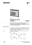
CIM 100
The CIM 100 solution is an add-on communication module that
is to be fitted in a Grundfos pump, using a 10-pin connection.
In this setup, the pump will supply power to the CIM 100.
See fig. 1.
•
UPE Series 2000
•
GRUNDFOS MAGNA/MAGNA3
•
TPE Series 1000/2000
CIU 100
•
CRE/CRNE/CRIE
•
NBE
•
NKE
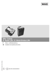
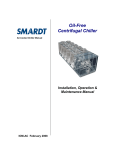
The CIU 100 solution is a box with a power supply module and
a CIM 100 LON module. It can either be mounted on a DIN rail or
on a wall. See fig. 2.
•
CHIE
•
MTRE
•
CUE
•
Hydro Multi-E.
This solution is used for Grundfos Hydro Multi-E and E-pumps
that do not support an internal, add-on communication module
(CIM 100). The enclosure class is IP54.
Pump with built-in CIM 100
References in the following:
The CIU unit is referred to as "LON unit".
•
The E-pumps, CUE, Hydro Multi-E, GRUNDFOS MAGNA and
MAGNA3 are referred to as "E-Pump".
The data in this document are subject to change without prior
notice. Grundfos cannot be held responsible for any problems
caused directly or indirectly by using information in this functional
profile.
LON network
Fig. 1
Example of CIM 100 solution
2.2 Assumptions
This functional profile assumes that the reader is familiar with
commissioning and programming LON devices. The reader
should also have some basic knowledge of the anatomy of LON
data communication.
Pump
object
Pump
object
LONLON
network
network
CIU 100
2.3 Definitions and abbreviations
CIM 100
Communication Interface Module 100
CIU 100
Communication Interface Unit 100
CP
Configuration Properties
DRF
Device Resource Files
GENIbus
Proprietary Grundfos fieldbus standard
H
Pressure (Head)
LED
Light-Emitting Diode
LON
Local Operating Network
nci
Network configuration property input
nro
Read-only configuration property
nv
Network variable
nvi
Network variable input
nvo
Network variable output
Q
Flow
R100
Grundfos remote control
SCPT
Standard Configuration Property Type
SNVT
Standard Network Variable Type
UCPT
User-defined Configuration Property Type
UFPT
User-defined Functional Profile Type
UNVT
User-defined Network Variable Type
TM05 2934 0712
The CIM 100 is referred to as "LON module".
•
Fig. 2
GENIbus
GENIbus
RS-485
RS-485
TM04 2329 2508
•
Example of CIU 100 solution
3
English (GB)
2. Introduction
English (GB)
3. Installation
The LON module is programmed on delivery.
This means that the application program will start when the power
supply is switched on.
The customer has to install the network, including assignment of
module addresses, and make the required bindings.
4
4.1 Connecting the LON module
The LON module is designed using an FT 3150 neuron
transceiver, an FT-X1 transformer and a 64 Kbyte flash memory
which enables updating of software.
Grundfos recommends to use a screened cable.
This functional profile is compliant with version 1.0 of "Pump
Controller Object" from LonMark International.
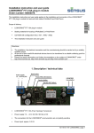
Fitting the cable
A LON network must be terminated. The termination depends on
the network topology chosen.
Procedure:
The LON module has been certified to adhere to LonMark
Application Layer interoperability guidelines 3.4.
See fig. 4.
1. Connect the conductors to terminal A (pos. 1).
Self-documentation strings are used. This means that an
installation tool can access the relevant information via the
network.
2. Connect the conductors to terminal B (pos. 2).
3. Connect the twisted screen ends to terminal "Screen" (pos. 3).
The XIF file can be found on the CD-ROM with this functional
profile.
The screen must only be connected to the screen
terminal of the CIM 100 LON module. See fig. 4,
pos. 3.
Note
The cable screen must never be connected to
earth via the earth clamp. See fig. 4, pos. 4.
The stripped part of the cable screen must be as
short as possible to reduce the impedance at
high frequencies.
Note
3
2
Pos.
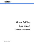
CIM 100 LON module
Designation
Description
1
A
LON terminal A
2
B
LON terminal B
3
Screen
LON terminal for cable screen
4
LED1
Yellow service LED
5
Pin
Service pin (push-button)
6
LED2
Red/green status LED for internal
communication between the
CIM 100 and the E-pump
Fig. 4
Pos.
TM04 1957 1508
Fig. 3
4 5 6
4
Connecting the LON module
Description
1
LON terminal A
2
LON terminal B
3
LON terminal for cable screen
4
Earth clamp
4.2 Registration in a LON network
E-pumps with a CIM 100 LON module are registered by a LON
network in one of these ways:
•
Service pin
•
Bar code label.
Service pin
When the service pin push-button of the module is activated, the
module will send a unique 48 bit ID code (Neuron ID) which is
registered in the LON network. See fig. 5.
1
Fig. 5
TM04 1958 1508
1 2 3
TM04 1956 1508
1
Service pin
Bar code label
The Neuron ID on the module or on the enclosed bar code label is
scanned and registered in the LON network. The bar code of the
Neuron ID is in Code 128 format. The additional bar code label
can be attached to the building installation plan.
5
English (GB)
4. CIM 100 LON module
4.3 LEDs
•
Yellow service LED (LED1)
•
Red/green status LED (LED2) for internal communication
between the CIM 100 and the E-pump.
4.3.1 LED1
The yellow LED on the CIM 100 functions as a service LED.
When the E-pump is connected to the power supply, the service
LED will flash once and then remain off if the installation has
been made correctly. In case of deviations, see section 17. Fault
finding and Echelon documentation.
The WINK command is supported by the LON module.
When the LON module receives a WINK command, the service
LED (LED1) will flash five times with 2-second intervals and a
duty cycle of 50 %. After five flashes, the service LED (LED1)
goes out. See fig. 6.
Service
LEDon
on
Service
LED
Service LED off
Service LED off
Fig. 6
1 sec.
1 sec.
sec.
11 sec.
TM04 2326 2308
English (GB)
The CIM 100 LON module has two LEDs. See fig. 3.
Flashing pattern
This flashing pattern must not be confused with the flashing
pattern of an unconfigured device which will flash with 1-second
intervals and a duty cycle of 50 %.
In a standard installation, the service LED (LED1) is permanently
off.
The use of a WINK command does not affect the operation of the
LON module in any way.
4.3.2 LED2
Status
Description
Off.
The CIM 100 has been switched off.
Flashing red.
No internal communication between the
CIM 100 and the E-pump.
Permanently red.
The CIM 100 does not support the
connected E-pump.
Permanently green.
Internal communication between the
CIM 100, and the E-pump is OK.
6
English (GB)
5. Considerations when installing the E-pump or
Hydro Multi-E
Flow has duplicate readouts (nvoFlow, nvoFlowF). Both NVOs
are active at all times.
For an E-pump with a maximum flow higher than 650 m3/h,
the nvoFlow will display the invalid value (655.35 m3/h, 0xFFFF)
for pump flows above this limit.
At the time of installation, it should be determined which of the
flow NVOs to monitor.
For an E-pump with a maximum flow higher than 650 m3/h,
nvoFlowF should be used.
For an E-pump with a maximum flow lower than 650 m3/h,
nvoFlow should be used as it offers a higher resolution.
See description of the NVOs in section 11. Pump controller
functional block details.
For further details about the configuration, see the documentation
for the relevant E-pump.
7
English (GB)
6. Power-on behaviour
A Grundfos LON module is designed to run with the following
LON configuration:
•
Node ID: 1
•
Subnet ID: 1
•
Domain ID: 00:00:00:00:00:00 (6 bytes).
The LON module will immediately start operating with these
settings on the LON network when the power supply is first
switched on. These settings can be changed with an installation
tool (not supplied by Grundfos).
If the LON module is switched off and on (power cycle), the actual
NV values in the LON module will be lost and reset to their default
values. The NV default values can be found in section 11. Pump
controller functional block details.
CP values are preserved in the LON module over power cycles.
When switched on, the LON module will apply control mode as
per the value of the CP nciControlMode. No other operation of the
E-pump is applied until an update of any of the following NVs is
received via the LON network:
•
nviPumpSetpoint
•
nviPumpOpMode
•
nviOvdStop
•
nviOvdPress
•
nviOvdSpeed.
When an update is received, the LON module will start operating
the E-pump.
The LON module will poll the following NVs immediately after
power-on (if they are bound):
•
nviPumpSetpoint
•
nviPumpOpMode.
The LON module will continue to poll these NVs with 10-second
intervals (if they are bound) until an update of any of the following
NVs is received via the LON network:
•
nviPumpSetpoint
•
nviPumpOpMode
•
nviOvdStop
•
nviOvdPress
•
nviOvdSpeed.
8
English (GB)
7. SNVT/UNVT details
Network variables of the node object are described in
section 12. Node object functional block details.
7.1 Network variable inputs
NV #
Name
SNVT type
SNVT index
Description
1
nviPumpSetpoint
SNVT_switch
95
Setpoint for normal operation
2
nviPumpOpMode
SNVT_hvac_mode
108
Requested operating mode
6
nviPumpOvdStop
SNVT_switch
7
nviOvdSpeed
SNVT_lev_percent
81
Override speed setpoint
8
nviOvdPress
SNVT_press
30
Override pressure setpoint
10
nviRemotePress
SNVT_press
30
Sensor input, remote differential-pressure sensor
11
nviRemoteFlow
SNVT_flow_p
161
Sensor input, remote flow sensor
95
Pump override stop command
7.2 Network variable outputs
NV #
Name
Send heartbeat
SNVT type
SNVT index
Description
3
nvoPumpCapacity
Yes
SNVT_lev_percent
81
Pump capacity as percent of maximum
4
nvoEffOpMode
Yes
SNVT_hvac_mode
108
Effective operating mode
Effective device control mode
5
nvoControlMode
Yes
SNVT_dev_c_mode
162
13
nvoPumpStatus
Yes
SNVT_dev_status
173
Pump status, diagnostic information
14
nvoPressure
No
SNVT_press
30
Pump pressure
15
nvoFlow
No
SNVT_flow_p
161
Pump flow
16
nvoSpeed
No
SNVT_rpm
102
Pump speed
17
nvoPumpOverride
No
SNVT_switch
95
Pump override active
18
nvoRuntime
No
SNVT_time_hour
124
Operating hours
19
nvoPumpFault
No
SNVT_dev_fault
174
Fault status
21
nvoFluidTemp
No
SNVT_temp_p
105
Liquid temperature
22
nvoPower
No
SNVT_power
27
Electrical power consumption in watt
23
nvoPowerK
No
SNVT_power_kilo
28
Electrical power consumption in kilowatt
24
nvoEnergyConsum
No
SNVT_elec_kwh
13
Total pump energy consumption
Note
NV # number is according to
SFPTpumpController.
7.3 Manufacturer-defined network variables
Name
SNVT type
SNVT index
Description
nvoFlowF
SNVT_flow_f
53
Flow (floating point)
nvoRemoteFlow
SNVT_flow_f
53
Remote flow (floating point)
nvoRemotePress
SNVT_press
30
Remote pressure
nvoRemoteTemp
SNVT_temp
105
Remote temperature 1
nvoRemoteTemp2
SNVT_temp
105
Remote temperature 2
nvoEnergyConsumL
SNVT_elec_kwh_l
146
Energy consumption
nvoInletPressure
SNVT_press
30
Inlet pressure
nvoLevel
SNVT_length_f
54
Tank level
nvoAuxSensor
SNVT_lev_percent
81
Actual setpoint in %
nvoTotalOnTime
SNVT_time_hour
124
Total power-on time
nvoAlarmCode
SNVT_cont
8
Current system alarm code
nvoWarningCode
SNVT_cont
8
Current system warning code
nviGrundfosCmd
UNVT_GF_cmd
nvoGrundfosInfo
SNVT_str_asc
36
Sw/hw version according to nviGrundfosCmd
nvoPumpStatusOld
SNVT_state
83
Duplicate of nvoPumpStatus
nvoPumpFaultOld
SNVT_state
83
Duplicate of nvoPumpFault
nvoHeatEnergyCnt
SNVT_elec_kwh
146
Accumulated heat energy in total pump life time
nvoHeatPower
SNVT_power_kilo
28
Current heat power
nvoHeatTempDiff
SNVT_temp_p
105
Diff. temperature between forward and return pipes
Request for sw/hw version
9
English (GB)
8. SCPT/UCPT details
8.1 Configuration properties
SCPT name
NV name
Type or SNVT
SCPT index
Associated NVs
Description
SCPTmaxSendTime
nciSndHrtBt
SNVT_time_sec (107)
49
nv3, nv4, nv5, nv13
Maximum period of time that will elapse before the
functional block automatically updates the
associated network variables.
SCPTpumpCharacteristic
nroPumpChar
(structure)
233
Entire functional block
Maximum flow, maximum pressure and maximum
speed of the pump define the pump characteristics.
SCPTlocation
nciLocation
SNVT_str_asc (36)
17
Entire functional block
Used to provide physical location of the device.
SCPTmaxFlowSetpoint
nciFlowHighLim
SNVT_flow_p (161)
237
Entire functional block
Used to limit the flow.
SCPTdeviceControlMode
nciControlMode
SNVT_dec_c_mode (162)
238
Entire functional block
Control mode for normal operation.
UCPT_Kp
nciKp
SNVT_multiplier (82)
Entire functional block
Gain for PI controller.
UCPT_Ti
nciTi
SNVT_time_sec (107)
Entire functional block
Integral time for PI controller.
UCPT_Ts
nciTs
SNVT_time_sec (107)
Entire functional block
Sample time for PI controller.
10
English (GB)
9. Application examples
9.1 Complete LON-based system
Any HVAC unit can use the pump object, either as an actuator
where the pump speed is used to control the flow or pressure in
the HVAC application, or the pump can be used as an intelligent
device which can maintain a constant pressure in the system.
In both cases, the pump can be monitored and manually
controlled via the system.
In the following example, the pump is used as an intelligent
device which is operating in PRESS_COMP control mode.
The pump will automatically lower the pressure setpoint in
proportion to the system flow. The unit changes the pump to
minimum mode during the night via nviPumpOpMode and
receives status of the pump operating mode from nvoEffOpMode.
The HVAC unit uses nvoPumpStatus to retrieve status
information from the pump. The controller can use this
information to check pump faults and hardware overrides and
whether the pump is running or not.
The pump is connected to a manual stop button which can be
used to stop the pump. When the pump is stopped via
nviPumpOvdStop, the HVAC unit can no longer control the pump
via the normal setpoint.
The example also shows a local control and monitoring panel.
Via this panel, the pump fault status as well as the pump flow and
pressure can be viewed. Via this local control panel, it is possible
to allocate a pressure setpoint to the pump. The pump will
maintain a constant pressure which will override the HVAC unit.
The whole system is monitored via a main system.
HVAC
unit
HVAC-unit
Pump
Pumpobject
object
Local
control
and&monitoring
Local
Control
Monitor Panel
panel
nviPumpCapacity
nvoPumpSetpoint
nviPumpSetpoint
nvoPumpCapacity
nviEffOpMode
nvoPumpOpMode
nviPumpOpMode
nvoEffOpMode
nviPumpOvdStop
nvoPumpStatus
nviPumpStatus
nviOvdpress
nvoPressure
nviPumpFlow
nvoFlow
nviPumpPress
nviPumpStatus
nvoOvdpress
Manual
Manualstop
stopbutton
button
Main
Maincontrol
control unit
unit
Fig. 7
TM04 2322 2508
nvoPumpSwitch
LON-based control system
11
9.2 Control with combined LON/AO/DO
Sensor
signal
sensor
signal
Management
(PMU)
Management(PUM)
RS-485
RS485
Controller
(PFU)
Controller(PFU)
GENIbus
IO for one
pump (max.
eight pumps
IO
1 pump
onfor
PFU)
(max 8 pumps
on PFU)
RS-485
RS485
Pump with terminal box
Alarm
Alarm
AO
DO
Pressure
transmitter
Pressure
transmitter
Pipe
Pipe
Pump with terminal box
AI
DI
PT
DO
Setpoint
Setpoint
AI
Start/Stop
Start/Stop
DI
RS-485
RS485
GENIbus
LON
controller
LON Controller
AI =AIAnalog
input Input
= Analogue
= Analogue Output
AO =AO
Analog
output
(G10)
nvoOperationMode
Pipe
Pipe
nviPumpOpMode
DI = Digital Input
DI =DO
Digital
input
= Digital
Output
RS-485
RS485
DO = Digital output
nviPumpOpmode=HVAC_OFF
nvoPressure
nvoFlow
nvoPumpStatus
nvoPumpFault
¨¨
Fig. 8
Control with combined LON/AO/DO
The LON controller forces the pump to "local control" by setting
nviPumpOpMode to HVAC_OFF. In this way, the pump can be
controlled via the analog and digital inputs (AI/DI) on the pump if
it has been set up to do so with the Grundfos R100 remote
control.
Pump status as well as pressure and flow readings can still be
obtained via LON.
12
TM04 2325 2508
English (GB)
It is possible to control the pump via analog and digital outputs
(AO/DO), e.g. when using the Grundfos PMU 2000 / PFU 2000,
and to combine this with the monitoring features of a LON
system.
English (GB)
9.3 Twin-head pump functionality with LON module
and two single pumps
With the LON module, it is possible to use a twin-head pump
setup for two single pumps as shown in fig. 9.
LONController
controller
LON
Twin Pump Logic
Twin-pump
logic
nvoSetpoint Pump1
nvoSetpoint Pump2
nviPressurePump1
nviPressurePump2
LONModule
module
LON
Pump
Pump
Logic for displaying system pressure:
GENIbus
GENIbus
communication
communication
GENIbus
GENIbus
communication
communication
nvoPressure
Logic for displaying system pressure:
System pressure
= nviPressurePump1
or
System
pressure
= nviPressurePump1
or nviPressurePump2
System Pressure = nviPressurePump2
Note: NOT system pressure = nviPressurePump1 + nviPressurePump2
Fig. 9
TM04 2331 2508
nviPumpSetpoint
nviPumpSetpoint
nvoPressure
Pump
Pump
LONModule
module
LON
Twin-head pump setup with LON module
The LON controller must handle all twin-head pump functionality
(alternating or standby duty) and control the pumps as required.
9.4 Twin-head pump functionality with two LON
modules and one twin-head pump
With two LON modules, it is possible of use a "real" twin-head
pump as shown in fig. 10.
LON
module
LON Controller
PumpLogic
logic
Pump
nvoSetpoint TwinPump
nviPressurePump1
Twin-pump
LON module
LON Module
Twin-pump
Twin
Pump
(pump
(pump1) 1)
nviPumpSetpoint
nviPumpSetpoint
nvoPressure
Logic for displaying system pressure:
GENIbus
GENIbus
communication
communication
Logic for displaying system pressure:
System pressure
= nviPressurePump1
or
System
pressure
= nviPressurePump1
or nviPressurePump2 (read from the
Systemthat
Pressure
= nviPressurePump2
pump
is running)
(read from pump that is running)
Note: NOT system pressure = nviPressurePump1 + nviPressurePump2
(NB: NOT System Pressure = nviPressurePump1 +
LON
module
LON Module
Twin Pump
(pump 2)
(pump 2)
nvoPressure
GENIbus
GENIbus
communication
communi-
cation
Twin-pump
cable
Twin pumpconnection
connection cabel
TM04 2332 2508
nviPressurePump2
Fig. 10 Twin-head pump setup with LON control
The LON controller must handle the twin-head pump as a normal
pump. The setpoint output of the LON controller shall be bound to
both LON modules controlling the two pump heads of the twinhead pump.
The twin-head pump will handle all twin-head pump functionality
itself. Both heads of the twin-head pump will receive the setpoint
via LON. The active pump head will react to the received setpoint.
13
The pump controller profile includes network variable inputs to
manually override the operation of the pump. A valid value on any
of these variable inputs changes the pump to override mode.
The pump will not return to normal setpoint control until all
manual override inputs are invalid. The override priority can be
seen in fig. 11.
Pump stopped.
nv6
nviPumpOvdStop
SNVT_switch
Value
"STOP"?
Value “STOP”
?
YES
YES
Pump stopped
NO
No
nv7
nv8
nviOvdSpeed
SNVT_lev_percent
One
valuesvalid
valid?
Oneof
of the
the values
?
YES
YES
nviOvdPress
The pump is operating
with
the speed
fromtheone
The pump
works with
of
the from
validone
inputs
speed
of the(last
valid
inputs
(last one wins)
one
wins).
SNVT_press
NO
No
HVAC_ECONOMY
OR
or
HVAC_NIGHT_PURGE ?
nv2
YES
YES
The pump is operating
with reduced energy
The pump works with reduced
consumption.
energy consumption
nviPumpOpMode
SNVT_hvac_mode
HVAC_MRNG_WRMUP
OR
or
HVAC_PRE_COOL
The pump is operating at
maximum performance.
YES
YES
The pump works with the
highest performance
NO
No
nv10
nv11
nv1
nviRemotePress
SNVT_press
YES
YES
SNVT_flow_p
nviPumpSetpoint
SNVT_switch
Fig. 11 Override functionality
14
Sensor
input
Sensor
inputvalid?
valid ?
nviRemoteFlow
The pump is operating
with
nviPumpSetpoint
The pump works with
according
to sensor
nviPumpSetpoint
according
range.
to <nciRemxxxRange>
NO
No
The pump is operating
The pump
works with
with
<nviPumpSetpoint>
<nviPumpSetpoint>
according
to the according
to pump instruction and
installation and operating
operation manual
instructions for the pump.
TM04 2337 2508
English (GB)
10. Override functionality
nv1
nviPumpSetpoint
SNVT_switch
nv3
nvoPumpCapacity
SNVT_lev_percent
nv2
nviPumpOpMode
SNVT_hvac_mode
nv4
nvoEffOpMode
SNVT_hvac_mode
nv5
nvoControlMode
SNVT_dev_c_mode
nv6
nviPumpOvdStop
SNVT_switch
nv13
nvoPumpStatus
SNVT_dev_status
nv7
nviOvdSpeed
SNVT_lev_percent
nv14
nvoPressure
SNVT_press
nv8
nviOvdPress
SNVT_press
nv15
nvoFlow
SNVT_flow_p
nv10
nviRemotePress
SNVT_press
nv16
nvoSpeed
SNVT_rpm
nv11
nviRemoteFlow
SNVT_flow_p
nv17
nvoPumpOverride
SNVT_switch
nv18
nvoRuntime
SNVT_time_hour
nv19
nvoPumpFault
SNVT_dev_f ault
nv21
nv20
nvoFluidTemp
nvoFlui
dSNVT_temp_p
nv22
nvoPower
SNVT_power
nv23
nvoPowerKilo
SNVT_power_kilo
nv24
nvoEnergyConsum
SNVT_elec_kwh
English (GB)
11. Pump controller functional block details
Manutacturer Defined
Manufacturer-defined
(see next page)
(see next page)
Configuration
Configuration
nciSndHrtBt
nciRcvHrtBt
nroPumpChar
nciFlowHighLim
nciControlMode
nc239
nc240
nc241
nc242
nciRemMinPress
nciRemMaxPress
nciRemMinFlow
nciRemMaxFlow
TM04 2335 0712
nc49
nc48
nc233
nc237
nc238
Fig. 12 Pump controller (standard part)
15
English (GB)
Mandatory and
Mandatory
andoptional
Optional
(Standard
seeprevious
previous
page)
(standard part,
part, see
page)
Manufacturer-defined
Manufacturer
Defined
nvoFlowF
SNVT_flow_f
nvoEnergyConsumL
SNVT_elec_kwh_l
nvoRemoteFlow
SNVT_flow_f
nvoInletPressure
SNVT_press
nvoRemotePress
SNVT_press
nvoRemoteTemp1
SNVT_temp_p
nvoRemoteTemp2
SNVT_temp_p
nvoAuxSensor
SNVT_lev_percent
nvoTotalOnTime
SNVT_time_hour
nv oActSetpoint
SNVT_lev_percent
nvoLevel
SNVT_length_f
nvoAlarmCode
SNVT_count
nvoWarningCode
SNVT_count
nvoPumpStatusOld
SNVT_state
nvoPumpFaultOld
SNVT_state
nvoHeatEnergyCnt
SNVT_elec_kwh
nvoHeatPower
SNVT_power
nvoHeatTempDiff
Configuration properties
Configuration Properties
(see previous page)
(see previous page)
Fig. 13 Pump controller (manufacturer-defined part)
16
TM04 2336 2508
SNVT_temp_p
11.1 Pump setpoint
network input SNVT_switch nviPumpSetpoint;
State Value
This network variable input provides start/stop control and a
setpoint. The setpoint is given as a percentage of the effective
maximum value (max. = 100 %). The setpoint value can
represent the pump speed, pump pressure or pump flow,
depending on the effective operating mode of the pump
(nvoControlMode).
0
Pump setpoint
high limit
Requested
speed
n/a
STOP
1
0
0%
STOP
1
1 to 200
0.5 to 100 %
0.5 to
100 %
1
201 to 255
100 %
100 %
Default value
Pump setpoint <nviPumpSetpoint> [%] 100 %
TM04 2392 2308
Effective pump setpoint
The pump will poll this network variable after power-up (if bound)
to ensure a correct start-up value. It will keep polling the bound
remote device with 10-second intervals until a valid value is
received in any of the following network variables:
nviPumpSetpoint, nviPumpOpMode, nviOvdPress, nviOvdSpeed,
nviPumpOvdStop.
Pump setpoint
low limit
STOP
Equivalent percent
Fig. 14 Effective setpoint for closed-loop operation
After power-up, a TPE Series 1000/2000 or CRE pump will
operate with the setpoint (and operating mode) of the local
settings of the pump until a valid input is given to any of the
following network variables: nviPumpSetpoint, nviPumpOpMode,
nviOvdPress, nviOvdSpeed, nviPumpOvdStop.
After power-up, a GRUNDFOS MAGNA or UPE Series 2000
pump will operate with the setpoint (and operating mode) of the
remote settings of the pump until a valid input is given to any of
the following network variables: nviPumpSetpoint,
nviPumpOpMode, nviOvdPress, nviOvdSpeed, nviPumpOvdStop.
The default value for nviPumpSetpoint is State = 0, Value = 0.0.
Pump setpoint low limit
X
≅
Pump setpoint high limit
X
≅
Remote sensor high value
Product availability
x 100 %
For product availability, see overview on page 36.
or
Remote sensor low value
x 100 %
Example
If the control mode is constant pressure (nvoControlMode =
DCM_PRESS_CONST), and the setpoint limits for this control
mode are 10 kPa and 100 kPa, "X" can be calculated to 10 %.
This means that a setpoint value of 1 to 10 % provides a setpoint
of 10 kPa (0 % stops the pump).
A setpoint value of 11 to 100 % provides a setpoint of
11 to 100 kPa.
Valid range
For n-state pumps:
State Value
Equivalent percent
Requested
speed
0
n/a
n/a
STOP
1
0
0%
STOP
1
1 to (1/n) 200
0.5 % to (1/n) 100 %
Pump
speed #1
1
1 + (1/n) 200 to
(2/n) 200
0.5 % + (1/n) 100 % to
(2/n) 100 %
Pump
speed #2
1
1 + ((m-1)/n)
200 to (m/n) 200
0.5 % + ((m-1)/n) 100 %
to (m/n) 100 %
Pump
speed #m
1
1 + ((n-1)/n)
200 to 200
0.5 % + ((n-1)/n) 100 %
to 100 %
Pump
speed #n
17
English (GB)
For variable-speed pumps
11.2 Requested pump operating mode
English (GB)
network input SNVT_hvac_mode nviPumpOpMode;
This network variable input is typically used by a supervisory
controller to override the pump controller operating mode. If the
requested mode is not supported by the unit, the unit will treat it
as an invalid value (treated as HVAC_NUL).
When the mode is HVAC_AUTO, the nviPumpSetpoint defines
the setpoint of the pump.
When the mode is HVAC_MRNG_WRMUP or
HVAC_PRE_COOL, the pump operates at maximum capacity.
To save energy during the night, in the summer or under low-load
conditions, the mode HVAC_ECONOMY or
HVAC_NIGHT_PURGE can be used. In this mode, the pump
operates at minimum capacity.
Valid range
Value
Identifier
Description
0
HVAC_AUTO
Normal operation: nviPumpSetpoint defines the effective setpoint.
2
HVAC_MRNG_WRMUP
Morning warm-up: maximum-capacity mode.
4
HVAC_NIGHT_PURGE
Night purge: minimum-capacity mode.
5
HVAC_PRE_COOL
Morning cool-down: maximum-capacity mode.
6
HVAC_OFF
The pump has been set to local mode via the network. In this mode, it
cannot be controlled via the network, but it will continue to monitor its
outputs.
13
HVAC_ECONOMY
Energy saving: minimum-capacity mode.
-1 (0xFF)
HVAC_NUL
Invalid value.
The LON module will poll this network variable after power-up
(if bound) to ensure a correct start-up value. It will keep polling
the bound remote device with 10-second intervals until a valid
value is received in any of the following network variables:
nviPumpSetpoint, nviPumpOpMode, nviOvdPress, nviOvdSpeed,
nviPumpOvdStop.
After power-up, the pump will operate with the operating mode
(and setpoint) of the local settings of the pump until a valid input
is given to any of the following network variables:
nviPumpSetpoint, nviPumpOpMode, nviOvdPress, nviOvdSpeed,
nviPumpOvdStop.
Default value
The default value for nviPumpOpMode is HVAC_AUTO.
Product availability
For product availability, see overview on page 36.
11.3 Pump capacity
network output SNVT_lev_percent nvoPumpCapacity;
This network variable output provides the actual pump capacity
as a percentage of the effective maximum-setpoint value
(pump-specific setpoint high limit). A value of more than 100 %
means that the pump is providing a value that is higher than the
highest possible setpoint.
Valid range
-163.840 to 163.830 % (0.005 % or 50 ppm).
The value of 0x7FFF (163.835 %) represents invalid data and
indicates that the capacity cannot be estimated.
When transmitted
This value is transmitted immediately when it has changed more
than 0.5 % for nvoControlMode = DCM_SPEED_CONST or more
than 2 % for other values of nvoControlMode.
Additionally, this network variable will be transmitted as a
heartbeat output on a regular basis as specified by the maximum
send time nciSndHrtBt configuration property.
Product availability
For product availability, see overview on page 36.
18
English (GB)
11.4 Actual setpoint
network output SNVT_lev_percent nvoActSetpoint;
This network variable output provides the actual pump setpoint
as a percentage of the effective maximum-setpoint value
(pump-specific setpoint high limit). This value makes it possible to
monitor the influence that the control algorithm of e.g.
proportional-pressure control has on the setpoint.
Valid range
-163.840 to 163.830 % (0.005 % or 50 ppm).
The value of 0x7FFF (163.835 %) represents invalid data and
indicates that the actual setpoint cannot be estimated.
When transmitted
This value is transmitted immediately when it has changed more
than 0.5 %.
Product availability
For product availability, see overview on page 36.
11.5 Effective operating mode
network output SNVT_hvac_mode nvoEffOpMode;
This network variable output provides the actual pump operating
mode.
Valid range
Value
Identifier
Description
0
HVAC_AUTO
Normal operation: nviPumpSetpoint defines the effective setpoint.
2
HVAC_MRNG_WRMUP
Morning warm-up: maximum-capacity mode.
4
HVAC_NIGHT_PURGE
Night purge: minimum-capacity mode.
5
HVAC_PRE_COOL
Morning cool-down: maximum-capacity mode.
6
HVAC_OFF
The pump has been set to local mode via the network. In this mode,
it cannot be controlled via the network, but it will continue to monitor its
outputs.
13
HVAC_ECONOMY
Energy saving: minimum-capacity mode.
HVAC_NUL
Invalid value.
-1 (0xFF)
When transmitted
This value is transmitted immediately when it has changed.
Additionally, this network variable will be transmitted as a
heartbeat output on a regular basis as specified by the maximum
send time nciSndHrtBt configuration property.
Product availability
For product availability, see overview on page 36.
19
11.6 Effective device control mode
This network variable output provides the actual control mode of
the pump. The actual control mode is determined by
nciControlMode, nviOvdSpeed, nviOvdPress, nviRemotePress or
nviRemoteFlow. See fig. 11 in section 10. Override functionality.
Valid range
Control mode
Description
The E-pump setpoint will be interpreted as percentage of the maximum
open-loop performance of the E-pump.
Q
DCM_PRESS_CONST (1)
The pump is operating in
constant-pressure mode.
The E-pump setpoint will be interpreted as pressure setpoint.
The E-pump will maintain a constant pressure. If the pump is in local
operation with a control mode which is not available via the LON, for
instance "Constant level", the control mode will be mapped to
DCM_PRESS_CONST on the LON. It will only be possible to select
these special control modes from the pump display or via remote
control when the LON module is in HVAC_OFF mode.
H
Q
TM04 2290 2308
DCM_SPEED_CONST (0)
The pump is operating in
open-loop mode.
TM04 2289 2308
H
DCM_PRESS_COMP (2)
The pump is operating in
compensated-pressure mode.
Q
TM04 2291 2308
H
The E-pump setpoint will be interpreted as basic setpoint for the
compensated-pressure mode (the black dot in the drawing).
The E-pump will maintain a constant pressure, but automatically lower
the actual pressure setpoint dependent on the flow (flow compensation,
the straight line in the drawing).
DCM_FLOW_CONST (3)
The pump is operating in
constant-flow mode.
The E-pump setpoint will be interpreted as flow setpoint.
The E-pump will maintain a constant flow.
Q
TM04 2288 2308
H
H
The E-pump setpoint will be interpreted as temperature setpoint.
The E-pump will maintain a constant temperature.
Q
TM04 2287 2508
DCM_TEMP_CONST (5)
The pump is operating in
constant-temperature mode.
Q
TM04 2287 2508
English (GB)
network output SNVT_dev_c_mode nvoControlMode;
H
DCM_PRESS_AUTO (7)
The pump is operating in
constant-pressure mode.
In this mode, the setpoint has no effect except for starting and stopping
the E-pump. The actual pressure setpoint of the E-pump is chosen and
optimised automatically by the E-pump to suit the needs of the
installation in the most effective way.
DCM_FLOW_CONST is only available for GRUNDFOS MAGNA
pumps with a remote flow sensor connected via the LON network
or TPE Series 1000 or CRE pumps with a flow sensor.
DCM_TEMP_CONST is only available for TPE Series 1000 or
CRE pumps with a temperature sensor and for the MAGNA3
pump.
DCM_PRESS_AUTO is not available for all pumps.
For some TPE Series 1000 or CRE pumps, all control modes are
not available at the same time. The control mode is determined
by the sensor connected to the pump.
Maximum flow limit (nciFlowHighLim) can be enabled for
MAGNA3 and TPE 2000 (versions H/I) pumps to limit the flow of
the pump.
20
Sensor type
SPEED_CONST
PRESS_CONST
PRESS_COMP
FLOW_CONST
TEMP_CONST
PRESS_AUTO
Pressure
●
-
-
-
●
●
-
-
Flow
-
-
-
Temperature
●
-
-
●
-
●
-
PRESS_COMP
FLOW_CONST
TEMP_CONST
PRESS_AUTO
Control modes for TPE Series 2000 / UPE Series 2000 /
GRUNDFOS MAGNA Series
Pump type
SPEED_CONST
PRESS_CONST
TPE Series 2000
●
●
●
H
H
H
UPE Series 2000
●
●
●
-
-
-
MAGNA
●
●
●
-
3
●
MAGNA with LON
pressure sensor
-
●
-
-
-
-
MAGNA with LON
flow sensor
-
-
-
●
-
-
3: Only available on MAGNA3.
H: Only available on version H/I and later.
When transmitted
This value is transmitted immediately when it has changed.
Additionally, this network variable will be transmitted as a
heartbeat output on a regular basis as specified by the maximum
send time nciSndHrtBt configuration property.
Product availability
For product availability, see overview on page 36.
21
English (GB)
Control modes for TPE Series 1000 / CRE / CRNE / CRIE /
NBE / NKE / CHIE / MTRE / CUE
English (GB)
11.7 Pump override stop command
11.9 Override pressure setpoint
network input SNVT_switch nviPumpOvdStop;
network input SNVT_press nviOvdPress;
This network variable input provides a manual override function
to stop the pump, typically from a supervisory controller.
The value of "OVDSTOP" in the table below stops the pump and
has a higher priority than the value of the pump setpoint
nviPumpSetpoint, the two remote sensor inputs nviRemotePress
and nviRemoteFlow, a value on nviPumpOpMode other than
HVAC_AUTO and the two override setpoints nviOvdSpeed and
nviOvdPress.
This network variable input provides an override request and
a pressure setpoint, typically from a supervisory controller.
When a valid value is received and the pump override stop
command is not active, the current pump setpoint
(nviPumpSetpoint or nviOvdSpeed) will be overridden, and the
pump will be controlled according to the given pressure setpoint.
The pump then operates in the DCM_PRESS_CONST mode.
The manual override status of the pump controller is indicated in
nvoPumpOverride.
Valid range
State
Value
Equivalent percent
Requested operation
0
n/a
n/a
NORMAL
1
0
n/a
NORMAL
1
1 to 255
n/a
OVDSTOP
n/a
n/a
Invalid (NORMAL)
0xFF
Default value
The default value is 0xFFFF (invalid value) in the state field.
The value will be adopted at power-up.
Product availability
For product availability, see overview on page 36.
Invalid values of all override setpoint inputs (nviOvdSpeed or
nviOvdPress) and a normal status of the pump override stop
command (nviPumpOvdStop) will change the pump back to
NORMAL mode. The manual override status of the pump
controller is indicated in the nvoPumpOverride network variable.
The control flow can be seen from fig. 11.
Valid range
-3,276.8 to 3,276.7 kPa (0.1 kPa).
The value of 0x7FFF (3,276.7 kPa) represents invalid data that
must be interpreted as "no override requested".
A value below the manufacturer-defined setpoint low-limit will be
saturated to this value, and the
nvoPumpStatus.pump_ctrl.setpt_out_of_range (setpoint out of
range) will be set (1).
A value above the manufacturer-defined setpoint high-limit will be
saturated to this value, and the
nvoPumpStatus.pump_ctrl.setpt_out_of_range (setpoint out of
range) will be set (1).
11.8 Override speed setpoint
Default value
network input SNVT_lev_percent nviOvdSpeed;
The default value is 0x7FFF (invalid value). The value will be
adopted at power-up.
This network variable input provides an override request and a
speed setpoint, typically from a supervisory controller. This speed
setpoint is given as a percentage of the maximum speed of the
pump. When a valid value is received and the pump override stop
command is not active, the current pump setpoint
(nviPumpSetpoint or nviOvdPress) will be overridden, and the
pump will be controlled according to the given speed setpoint.
The pump then operates in the DCM_SPEED_CONST mode.
Invalid values of all override setpoint inputs (nviOvdSpeed and
nviOvdPress) and a normal status of the pump override stop
command (nviPumpOvdStop) will change the pump back to
NORMAL mode. The manual override status of the pump
controller is indicated in the nvoPumpOverride network variable.
The control flow can be seen from fig. 11.
Valid range
-163.840 to 163.830 % (0.005 % or 50 ppm).
The value of 0x7FFF (163.835 %) represents invalid data that
must be interpreted as "no override requested".
A negative value will be interpreted as 0 %, and the
nvoPumpStatus.pump_ctrl.setpt_out_of_range (setpoint out of
range) will be set (1).
A value of more than 100 % will be interpreted as 100 %, and the
nvoPumpStatus.pump_ctrl.setpt_out_of_range (setpoint out of
range) will be set (1).
Default value
The default value is 0x7FFF (invalid value). The value will be
adopted at power-up.
Product availability
For product availability, see overview on page 36.
22
Product availability
For product availability, see overview on page 36.
English (GB)
11.10 Remote pressure sensor input
network input SNVT_press nviRemotePress;
This network variable input allows the use of a remote differentialpressure sensor on the network as the feedback signal to the
pump controller.
This input will only have effect when the LON module is used with
a GRUNDFOS MAGNA pump. For other pump types, this input
will be ignored.
A valid value of the nviRemotePress variable will disable the
internal feedback signal of the pump controller and activate the
remote-sensor operating mode, thus forcing the pump to run in
constant-pressure control mode. This is indicated by the
nvoPumpStatus.pump_ctrl.remote_press (remote pressure
sensor) being set (1).
The nvoPumpCapacity variable will indicate the value of the
pressure signal from the sensor as a percentage of its maximum
value. This makes it possible to compare the sensor value with
the nviPumpSetpoint value.
The nvoPressure variable always indicates the differential
pressure across the pump flanges measured or estimated by the
pump controller. This may help analysing the behaviour of the
system.
When using nviRemotePress, the pressure setpoint is given by
nviPumpSetpoint. The ranging of both the setpoint and the
feedback is given by the configuration properties:
nciRemMinPress and nciRemMaxPress. These values are used
instead of the pump setpoint high- and low-limits.
When using nviRemotePress, the internal PI controller of the
pump can be adjusted by means of the configuration properties
nciKp, nciTi and nciTs. These configuration properties, including
nciRemMinPress and nciRemMaxPress, are associated with the
nviRemotePress network variable and can be identified by their
type in the installation tool.
For a description of the individual configuration properties,
see section 8.1 Configuration properties.
If the nviRemotePress variable receives an invalid value, or if the
heartbeat (specified by nciRcvHrtBt) is missing, remote control is
deactivated, and the pump controller will return to the control
mode defined by nciControlMode.
Any valid value in the manual override inputs has higher priority
than the remote-sensor control, and the pump controller will use
the internal feedback signals.
Pump
controller
Hydronic
system
Pump
Relative sensor Fb
Remote
pressure scale
Absolute sensor Fb
Remote
pressure
sensor
TM04 2320 2508
Pump setpoint
Fig. 15 Block diagram for remote pressure sensor
Valid range
-3,276.8 to 3,276.7 kPa (0.1 kPa).
The value of 0x7FFF (3,276.7 kPa) represents invalid data and
can be interpreted as "not connected".
Default value
The default value is 0x7FFF (invalid value). The value will be
adopted at power-up and if no update is received within the
specified "receive heartbeat" time.
Product availability
For product availability, see overview on page 36.
23
11.11 Remote flow sensor input
This network variable input allows the use of a remote flow
sensor on the network as the feedback signal to the pump
controller.
This input will only have effect when the LON module is used with
a GRUNDFOS MAGNA pump. For other pump types, this input
will be ignored.
A valid value of the nviRemoteFlow variable will disable the
internal feedback signal of the pump controller and activate the
remote-sensor operating mode, thus forcing the pump to run in
constant-flow control mode. This is indicated by the
nvoPumpStatus.pump_ctrl.remote_flow (remote flow sensor)
being set (1).
The nvoPumpCapacity variable will indicate the value of the flow
signal from the sensor as a percentage of its maximum value.
This makes it possible to compare the sensor value with the
nviPumpSetpoint value.
The nvoFlow output variable always indicates the flow through
the pump measured or estimated by the pump controller.
This may help analysing the behaviour of the system.
When using nviRemoteFlow, the flow setpoint is given by
nviPumpSetpoint. The ranging of both the setpoint and the
feedback is given by the configuration properties:
nciRemMinFlow and nciRemMinFlow). These values are used
instead of the pump setpoint high- and low-limits.
When using nviRemoteFlow, the internal PI controller of the pump
can be adjusted by means of the configuration properties nciKp,
nciTi and nciTs. These configuration properties, including
nciRemMinFlow and nciRemMaxFlow, are associated with the
nviRemoteFlow network variable and can be identified by their
type in the installation tool.
For a description of the individual configuration properties,
see section 8.1 Configuration properties.
If the nviRemoteFlow variable receives an invalid value, or if the
heartbeat (specified by nciRcvHrtBt) is missing, remote control is
deactivated, and the pump controller will return to the control
mode defined by nciControlMode.
Any valid value in the manual override inputs has higher priority
than the remote-sensor control, and the pump controller will use
the internal feedback signals.
Pump
controller
Hydronic
system
Pump
Pump setpoint
Relative sensor Fb
Remote flow
scale
Fig. 16 Block diagram for remote flow sensor
Valid range
0 to 655.34 m3/h (0.01 m3/h).
The value of 0xFFFF (655.35 m3/h) represents invalid data and
can be interpreted as "not connected".
Default value
The default value is 0xFFFF (invalid value). The value will be
adopted at power-up and if no update is received within the
specified "receive heartbeat" time.
Product availability
For product availability, see overview on page 36.
24
Absolute sensor Fb
Remote flow
sensor
TM04 2319 2508
English (GB)
network input SNVT_flow_p nviRemoteFlow;
English (GB)
11.12 Pump status, diagnostic information
network output SNVT_dev_status nvoPumpStatus;
network output SNVT_state nvoPumpStatusOld;
This network variable output provides detailed diagnostic
information on the status of the pump controller.
nvoPumpStatusOld holds information identical to
nvoPumpStatus. It is added for backwards compatibility and is not
recommended for new designs.
Valid range
The bits below are supported.
Bit name
Bit no.
Description
nvoPumpStatus
nvoPumpStatusOld
0
device_fault
Bit 0
A pump-related fault or warning has been detected.
See section 11.23 Pump fault status for detailed information.
Some faults on UPE Series 2000 will be seen in this bit, but will not appear in
nvoPumpFault due to their general nature.
1
supply_fault
Bit 1
A system-related fault or warning has been detected.
See section 11.23 Pump fault status for detailed information.
3
speed_low
Bit 3
The pump is operating at the lowest possible speed. Therefore, the requested
performance is not possible.
4
speed_high
Bit 4
The pump is operating at the highest possible speed. Therefore, the requested
performance is not possible.
6
setpt_out_of_range
Bit 6
This bit is set if any of the override variables are out of range.
8
local_control
Bit 8
The pump has been set to local mode by hardware override (push-buttons on
pump, external STOP or with the R100).
10
running
Bit 10
The pump is running.
12
remote_press
Bit 12
The pump is using network pressure sensor.
13
remote_flow
Bit 13
The pump is using network flow sensor.
When transmitted
11.14 Pump inlet pressure
This value is transmitted immediately when it has changed.
network output SNVT_press nvoInletPressure;
Additionally, this network variable will be transmitted as a
heartbeat output on a regular basis as specified by the maximum
send time nciSndHrtBt configuration property.
This network variable output provides the system inlet pressure
as measured by the pump.
Product availability
For product availability, see overview on page 36.
11.13 Pump pressure
network output SNVT_press nvoPressure;
This network variable output provides the pressure across
the pump flanges as measured or estimated by the pump.
Valid range
-3,276.8 to 3,276.7 kPa (0.1 kPa).
The value of 0x7FFF (3,276.7 kPa) represents invalid data and
indicates that the pressure cannot be measured/estimated.
If no inlet pressure sensor is available in the system,
nvoInletPressure will display the invalid value.
Valid range
-3,276.8 to 3,276.6 kPa (0.1 kPa).
The value of 0x7FFF (3,276.7 kPa) represents invalid data and
indicates that the pressure cannot be measured or that no inlet
pressure sensor is connected.
When transmitted
This value is transmitted immediately when it has changed more
than 2 kPa.
Product availability
For product availability, see overview on page 36.
When transmitted
This value is transmitted immediately when it has changed more
than 2 KPa.
11.15 Remote pressure
Product availability
This network variable output provides the pressure measured
somewhere in the system with a pressure sensor connected to
the pump.
For product availability, see overview on page 36.
network output SNVT_press nvoRemotePress;
Valid range
-3,276.8 to 3,276.7 kPa (0.1 kPa).
The value of 0x7FFF (3,276.7 kPa) represents invalid data and
indicates that the pressure cannot be measured or that no remote
pressure sensor is connected.
When transmitted
This value is transmitted immediately when it has changed more
than 2 KPa.
Product availability
For product availability, see overview on page 36.
25
English (GB)
11.16 Pump flow (standard range)
11.18 Remote flow
network output SNVT_flow_p nvoFlow;
network output SNVT_flow_f nvoRemoteFlowF;
This network variable output provides the flow through the pump
as measured or estimated by the pump controller.
This network variable output provides the flow measured
somewhere in the system with a flow sensor connected to
the pump.
If the maximum pump flow is higher than 650 m3/h, nvoFlowF
should be used as it offers an extended range.
Section 5. Considerations when installing the E-pump or Hydro
Multi-E provides more information on the coherence of nvoFlow
and nvoFlowF.
Valid range
0 to 655.34 m3/h (0.01 m3/h).
Valid range
-3.40282E38 to 3.40282E38 l/s.
The value of 3.40282E38 l/s is not used as a physical
representation of the flow, but represents invalid data and
indicates that the flow cannot be measured or that no remote-flow
sensor is connected.
The value of 0xFFFF (655.35 m3/h) represents invalid data and
indicates that the flow cannot be measured/estimated or that the
flow is higher than 650 m3/h.
If no remote-flow sensor is available in the system, nvoFlowF will
display a value of NaN (Not a Number).
When transmitted
This value is transmitted immediately when it has changed more
than 0.2 m3/h.
When transmitted
This value is transmitted immediately when it has changed
significantly. The significance depends on the pump type.
Product availability
•
For UPE Series 2000, the value must change more than
0.2 m3/h.
For product availability, see overview on page 36.
•
For GRUNDFOS MAGNA, the value must change more than
0.3 m3/h.
11.19 Pump speed
•
For TPE Series 1000/2000, the value must change more than
0.5 m3/h.
network output SNVT_rpm nvoSpeed;
This optional network variable output provides the pump speed.
Product availability
Valid range
For product availability, see overview on page 36.
0 to 65,534 rpm (1 rpm).
11.17 Pump flow (extended range)
The value of 0xFFFF (65,535 rpm) represents invalid data and
indicates that the speed cannot be measured/estimated.
network output SNVT_flow_f nvoFlowF;
When transmitted
This network variable output provides the flow through the pump
as measured or estimated by the pump.
This value is transmitted immediately when it has changed more
than 107 rpm.
If the maximum pump flow is lower than 650 m3/h, nvoFlow
should be used as it offers a higher resolution.
Section 5. Considerations when installing the E-pump or Hydro
Multi-E provides more information on the coherence of nvoFlow
and nvoFlowF.
Valid range
-3.40282E38 to 3.40282E38 l/s.
If no flow sensor is available in the system, nvoFlowF will display
a value of NaN (Not a Number).
When transmitted
This value is transmitted immediately when it has changed more
than 1 l/s.
Product availability
For product availability, see overview on page 36.
11.20 Pump override active
network output SNVT_switch nvoPumpOverride;
This optional network variable output provides the manual
override status of the pump. This variable has the value
"OVERRIDE" in the table below if the pump setpoint has been
overridden by one of the variables: nviOvdSpeed, nviOvdPress or
nviOvdStop.
Valid range
Product availability
State
Value
Equivalent percent
Requested operation
For product availability, see overview on page 36.
0
0
0
NORMAL
1
200
100
OVERRIDE
0xFF
n/a
n/a
Invalid value
When transmitted
This value is transmitted immediately when it has changed.
Product availability
For product availability, see overview on page 36.
26
11.24 Heat energy metering
network output SNVT_time_hour nvoRuntime;
network output SNVT_elec_kwh nvoHeatEnergyCnt;
This network variable output provides the total number of
operating hours of the pump. After 65,535 hours, the counter is
reset and will restart from zero (0).
network output SNVT_power_kilo nvoHeatPower;
network output SNVT_temp_p nvoHeatTempDiff;
This value is transmitted immediately when it has changed.
These data points are used for heat energy metering by the
MAGNA3 and MGE model H pumps. In order to use the heat
energy meter function at the pump, an external sensor has to be
connected. Please note that this feature is not to be used for
billing purposes.
Product availability
network output SNVT_elec_kwh nvoHeatEnergyCnt;
For product availability, see overview on page 36.
Valid range
Valid range
0 to 65,535 hours (1 hour), (2,730 days or 7.67 years).
When transmitted
0 to 65,535 kWh (1 kWh).
11.22 Total ontime
The value of 0xFFFF (65,535 kWh) represents invalid data and
network output SNVT_time_hour nvoTotalOnTime;
indicates that the power consumption cannot be measured/
This network variable output provides the total number of hours
the pump has been powered on. After 65,535 hours, the counter
is reset and will restart from zero (0).
estimated.
When transmitted
This value is transmitted immediately when it has changed.
Valid range
Product availability
0 to 65,535 hours (1 hour), (2,730 days or 7.67 years).
For product availability, see overview on page 36.
If this variable is not supported by the pump, a value of 0 is
displayed.
network output SNVT_power_kilo nvoHeatPower;
When transmitted
This value is transmitted immediately when it has changed.
Valid range
0 to 6,553.4 kW (0.1 kW).
The value of 0xFFFF (6,553.5 kW) represents invalid data and
Product availability
indicates that the power cannot be measured/estimated or that
For product availability, see overview on page 36.
the power is higher than 6,500 kW.
11.23 Pump fault status
When transmitted
This value is transmitted immediately when it has changed more
network output SNVT_dev_fault nvoPumpFault;
than 2 W.
network output SNVT_state nvoPumpFaultOld;
Product availability
This network variable output provides fault information about
the pump, based on warnings and alarms from the pump.
nvoPumpFaultOld holds information identical to nvoPumpFault.
It is added for backwards compatibility and is not recommended
for new designs.
For product availability, see overview on page 36.
Note
General faults and some overtemperature faults
on UPE Series 2000 will not appear on
nvoPumpFault, but only on the
nvoPumpStatus.device_fault bit. Therefore,
a fault monitoring strategy should always include
monitoring of nvoPumpStatus.
For a description of nvoPumpStatus, see section 11.12 Pump
status, diagnostic information.
Both warnings and alarms will appear as faults in nvoPumpFault,
except for warning and alarm codes corresponding to
df_elect_failure and df_elect_failure_nf. For these, warnings will
appear as df_elect_failure_nf, and alarms will appear as
df_elect_failure.
network output SNVT_temp_p nvoHeatTempDiff;
Valid range
-273.17 to +327.66 °C (0.01 °C).
The value of 0x7FFF (327.67 °C) represents invalid data and
indicates that the temperature cannot be measured or that no
remote temperature-sensor is connected.
When transmitted
This value is transmitted immediately when it has changed more
than 1 °C.
Product availability
For product availability, see overview on page 36.
Valid range
The valid range of SNVT_dev_fault. The following two tables
show pump faults and their corresponding appearance on the
R100 remote control.
If the LON module is unable to communicate with the pump for
30 seconds, the df_elect_failure bit is set. The fault is visible on
the node object as well. See section 11. Pump controller
functional block details. This fault will not be visible when using
the R100.
27
English (GB)
11.21 Runtime
English (GB)
Pump faults, TPE Series 1000/2000 / CRE / CRNE / CRIE /
NBE / NKE / CHIE / MTRE / CUE / GRUNDFOS MAGNA Series
Bit no.
nvoPumpFault
nvoPumpFaultOld
Description
Corresponding warning/alarm on the R100
Undervoltage (40)
Undervoltage transient (41)
Cut-in fault (dV/dt) (42)
Inrush fault (155)
0
sf_voltage_low
Bit 0
Supply voltage is too low.
1
sf_voltage_high
Bit 1
Supply voltage is too high.
Overvoltage (32)
2
sf_phase
Bit 2
Power missing phase.
Electronic DC-link protection activated (ERP) (14)
3
sf_no_fluid
Bit 3
No liquid in pump.
Dry running (57)
4
sf_press_low
Bit 4
System pressure is too low. -
5
sf_press_high
Bit 5
System pressure is too
high.
Turbine operation (29)
Bit 8
Motor temperature is too
high.
Overtemperature (64)
Motor temperature 1 (65)
Temperature too high, internal frequency converter
module (t_m) (67)
8
df_motor_temp
9
df_motor_failure
Bit 9
Motor has fatal failure.
External fault signal (3)
Too many restarts (from standby mode per 24 hours)
(4)
Too many hardware shutdowns (short standbys
per minute) (7)
Overload (48)
Overcurrent (i_line, i_dc, i_mo) (49)
Motor protection function, general shutdown (mpf)
(50)
Motor protection function 3 sec. limit (54)
Motor current protection activated (MCP) (55)
Underload (56)
10
df_pump_blocked
Bit 10
Pump is blocked.
Blocked motor/pump (51)
Bit 11
Electronic temperature is
too high.
11
12
13
14
28
Bit name
df_elect_temp
df_elect_failure_nf
df_elect_failure
df_sensor_failure
Bit 12
Bit 13
Bit 14
Electronic non-fatal failure.
Warning codes:
Hardware fault, type 1 (72)
Hardware shutdown (HSD) (73)
Internal communication fault (76)
Communication fault, twin-head pump (77)
Hardware fault, type 2 (80)
Verification error, BE parameter area (EEPROM) (85)
Electronic rectifier protection activated (ERP) (105)
Electronic inverter protection activated (EIP) (106)
Communication fault, internal frequency converter
module (156)
Alarm and warning codes:
Verification error, FE parameter area (EEPROM) (83)
Electronic fatal failure.
CIM fault (Communication Interface Module) (not
visible on the R100) (159)
Alarm codes:
Leakage current (1)
Hardware fault, type 1 (72)
Hardware shutdown (HSD) (73)
Internal communication fault (76)
Communication fault, twin-head pump (77)
Hardware fault, type 2 (80)
Verification error, BE parameter area (EEPROM) (85)
Electronic rectifier protection activated (ERP) (105)
Electronic inverter protection activated (EIP) (106)
Communication fault, internal frequency converter
module (156)
Sensor failure.
Sensor fault (88)
Signal fault, (feedback) sensor 1 (89)
Signal fault, speed sensor (90)
Setpoint signal outside range (96)
Bit name
Bit no.
Description
Corresponding warning/alarm on the R100
Bit 0
Supply voltage is too low.
Undervoltage
sf_voltage_high
Bit 1
Supply voltage is too high.
Overvoltage
sf_phase
Bit 2
Power missing phase.
-
3
sf_no_fluid
Bit 3
No liquid in pump.
-
4
sf_press_low
Bit 4
System pressure is too low. -
5
sf_press_high
Bit 5
System pressure is too
high.
-
8
df_motor_temp
Bit 8
Motor temperature is too
high.
Overtemperature
nvoPumpFault
nvoPumpFaultOld
0
sf_voltage_low
1
2
9
df_motor_failure
Bit 9
Motor has fatal failure.
-
10
df_pump_blocked
Bit 10
Pump is blocked.
Pump blocked
11
df_elect_temp
Bit 11
Electronic temperature is
too high.
Overtemperature
12
df_elect_failure_nf
Bit 12
Electronic non-fatal failure.
-
13
df_elect_failure
Bit 13
Electronic fatal failure.
Communication fault between LON module and
pump (not visible on the R100)
14
df_sensor_failure
Bit 14
Sensor failure.
Differential-pressure sensor defective
Additional fault information can be retrieved with the Grundfos
R100 remote control.
When transmitted
This value is transmitted immediately when one of the bits has
changed.
Product availability
For product availability, see overview on page 36.
11.25 Alarm code
network output SNVT_count nvoAlarmCode;
This network variable output provides the currently active alarm
code from the pump.
English (GB)
Pump faults, UPE Series 2000
11.27 Liquid temperature
network output SNVT_temp_p nvoFluidTemp;
This network variable output provides the pumped-liquid
temperature.
Valid range
-273.17 to +327.66 °C (0.01 °C).
The value of 0x7FFF (327.67 °C) represents invalid data and
indicates that the temperature cannot be measured.
When transmitted
This value is transmitted immediately when it has changed more
than 1 °C.
Product availability
In case of a common communication interface module fault
(code 159), which is generated in the LON module solely, this will
be displayed in nvoAlarmCode and override any alarm pending in
the connected E-pump.
For product availability, see overview on page 36.
Valid range
network output SNVT_temp_p nvoRemoteTemp;
See section 18. Grundfos alarm and warning codes.
This network variable output provides the temperature measured
somewhere in the system with a temperature sensor connected
to the pump.
When transmitted
This value is transmitted immediately when it has changed.
Product availability
For product availability, see overview on page 36.
11.28 Remote temperature 1
Valid range
-273.17 to +327.66 °C (0.01 °C).
11.26 Warning code
The value of 0x7FFF (327.67 °C) represents invalid data and
indicates that the temperature cannot be measured or that no
remote temperature-sensor is connected.
network output SNVT_count nvoWarningCode;
When transmitted
This network variable output provides the currently active warning
code from the pump.
This value is transmitted immediately when it has changed more
than 1 °C.
Valid range
Product availability
See section 18. Grundfos alarm and warning codes.
For product availability, see overview on page 36.
When transmitted
This value is transmitted immediately when it has changed.
Product availability
For product availability, see overview on page 36.
29
English (GB)
11.29 Remote temperature 2
11.32 Power consumption in watts
network output SNVT_temp_p nvoRemoteTemp2;
network output SNVT_power nvoPower;
This network variable output provides the temperature measured
somewhere in the system with a temperature sensor connected
to the pump.
This optional network variable output provides the actual power
being consumed by the pump.
Valid range
0 to 6,553.4 W (0.1 W).
-273.17 to +327.66 °C (0.01 °C).
The value of 0xFFFF (6,553.5 W) represents invalid data and
indicates that the power cannot be measured/estimated or that
the power is higher than 6,500 W.
The value of 0x7FFF (327.67 °C) represents invalid data and
indicates that the temperature cannot be measured or that no
remote temperature-sensor is connected.
When transmitted
This value is transmitted immediately when it has changed more
than 1 °C.
Product availability
Valid range
When transmitted
This value is transmitted immediately when it has changed more
than 2 W.
Product availability
For product availability, see overview on page 36.
For product availability, see overview on page 36.
11.30 Tank level
network output SNVT_length_f nvoLevel;
This network variable output provides the liquid level in the tank
of the hydraulic system as measured by the pump.
11.33 Power consumption in kilowatts
network output SNVT_power_kilo nvoPowerKilo;
This optional network variable output provides the actual power
being consumed by the pump.
Valid range
Valid range
0 to 6,553.4 kW (0.1 kW).
0 to 3.40282E38 m.
The value of 0xFFFF (6,553.5 kW) represents invalid data and
indicates that the power consumption cannot be measured/
estimated.
A value of NaN (Not a Number) represents invalid data and
indicates that the level cannot be measured or that no level
sensor is connected.
If no level sensor is available in the system, nvoLevel will display
a value of NaN (Not a Number).
When transmitted
This value is transmitted immediately when it has changed more
than 0.01 m.
Product availability
For product availability, see overview on page 36.
When transmitted
This value is transmitted immediately when it has changed more
than 0.2 kW.
Product availability
For product availability, see overview on page 36.
11.34 Energy consumption (standard range)
network output SNVT_elec_kwh nvoEnergyConsum;
11.31 Auxiliary sensor input
network output SNVT_lev_percent nvoAuxSensor;
This network variable output enables the user to connect any kind
of sensor to the product (e.g. a pH sensor), but the interpretation
of 0 % and 100 % has to be managed somewhere else in the
system.
Valid range
-163.840 to 163.830 % (0.005 % or 50 ppm).
The value of 0x7FFF (163.835 %) represents invalid data and
indicates that no auxiliary sensor input is connected.
When transmitted
This value is transmitted immediately when it has changed more
than 0.1 %.
Product availability
For product availability, see overview on page 36.
This optional network variable output provides the accumulated
energy consumption of the pump. After 65,535 kWh, the counter
is reset and will restart from 0 kWh.
Valid range
0 to 65,535 kWh (1 kWh).
The value of 0xFFFF (65,535 kWh) represents invalid data and
indicates that the power consumption cannot be measured/
estimated.
When transmitted
This value is transmitted immediately when it has changed.
Product availability
For product availability, see overview on page 36.
11.35 Energy consumption (extended range)
network output SNVT_elec_kwh_l nvoEnergyConsumL;
This optional network variable output provides the accumulated
electrical energy consumption of the pump.
After 214,748,364.6 kWh, the counter is reset and will restart
from 0 kWh.
Valid range
-214,748,364.8 to 214,748,364.6 kWh (0.1 kWh).
The value of 0x7FFFFFFF (214,748,364.7 kWh) represents
invalid data and indicates that the electrical energy consumption
cannot be measured/estimated.
When transmitted
This value is transmitted immediately when it has changed.
Product availability
For product availability, see overview on page 36.
30
11.39 Maximum flow limit
network input SNVT_time_sec nciSndHrtBt;
Network input config SNVT_flow_p nciFlowHighLim;
This network configuration property input sets the maximum
period of time that will elapse before the functional block
automatically updates the following network variables:
This configuration property defines the maximum limit of the flow
of the pump. Applies to MAGNA3 and TPE 2000 version H and
later only. It can be enabled in all control modes.
nv3, nvoPumpCapacity
Valid range
nv4, nvoEffOpMode
The valid range is 0.0 to 655.34 m3/h.
nv5, nvoControlMode
nv13, nvoPumpStatus.
A value of 0xFFFF (655.35 m3/h) represents invalid data and will
disable the flow limit function.
Valid range
Default value
0.0 to 6,553.4 sec. (0.1 sec.).
The default value is 0xFFFF, i.e. disabled.
A value of 0xFFFF (6,553.5 sec.) represents invalid data and will
disable the automatic update function.
Product availability
A value of zero (0) will be used for the internal timer if the
configured value is invalid. The value of zero (0) disables the
"send heartbeat" function.
Only available on MAGNA3.
H
Default value
The default value is 0.0 (no automatic update).
Product availability
For product availability, see overview on page 36.
11.37 Receive heartbeat
This network configuration property input sets the maximum
period of time that will elapse before the functional block
automatically uses the default values for the following network
variables:
nv10, nviRemotePress
nv11, nviRemoteFlow.
Q
TM05 2950 0712
network input config SNVT_time_sec nciRcvHrtBt;
Fig. 17 Maximum flow limit
Valid range
0.0 to 6,553.4 sec. (0.1 sec.).
A value of 0xFFFF (6,553.5 sec.) represents invalid data and will
disable the automatic update function.
A value of zero (0) will be used for the internal timer if the
configured value is invalid. The value of zero (0) disables the
"receive heartbeat" function.
Default value
The default value is 0.0 (no automatic update).
Product availability
For product availability, see overview on page 36.
11.38 Control mode for normal operation
network input config SNVT_dev_c_mode
nciControlMode;
This network configuration property input defines the device
control mode to be used for the normal operating mode.
For more details about the control modes, see section
11.6 Effective device control mode.
Valid range
The valid range is the same as that of nvoControlMode.
Default value
The default control mode for a pump is DCM_PRESS_COMP
(value = 2).
Product availability
For product availability, see overview on page 36.
31
English (GB)
11.36 Send heartbeat
11.40 Pump characteristic
This read-only configuration property input provides the basic
characteristic data for the pump.
For further technical details, see installation and operating
instructions for the relevant pump or Hydro Multi-E.
The configuration parameter consists of three variables.
Valid range
The valid ranges of the supported pump characteristics are
shown below.
Variable
Description
Valid range
Invalid value
SNVT_rpm
Maximum pump speed
0 to 65,535 rpm
0xFFFF (65,535 rpm)
SNVT_press
Maximum pump pressure
-3,276.8 to 3,276.6 kPa
0x7FFF (3,276.7 kPa)
SNVT_flow_p
Maximum pump flow
3
0 to 655.35 m /h
0xFFFF (655.35 m3/h)
Maximum pressure at maximum speed and flow = 0
<PumpChar.PressMax>
Maximum speed
<PumpChar.SpeedMax>
Maximum flow at maximum speed and
pressure = 0
<PumpChar.FlowMax>
TM04 2393 2508
English (GB)
network input config SCPTpumpCharateristic
nroPumpChar;
Fig. 18 Pump characteristics
Default value
11.42 Remote pressure-sensor maximum value
nroPumpChar is a read-only property. The pump characteristic
will be set according to the connected pump.
SCPTmaxRemotePressureSetpoint cp_family
nciRemMaxPress;
Product availability
For product availability, see overview on page 36.
11.41 Remote pressure-sensor minimum value
SCPTminRemotePressureSetpoint cp_family
nciRemMinPress;
Basic network variable type for
SCPTminRemotePressureSetpoint: SNVT_press.
This network configuration property input provides the minimum
value for ranging the remote pressure sensor. Together with
nciRemMaxPress, these range values replace the normal
setpoint limits when the remote sensor is used.
See section 11.10 Remote pressure sensor input.
Valid range
-3,276.8 to 3,276.7 kPa (0.1 kPa).
The value of 0x7FFF (3,276.7 kPa) represents invalid data.
Default value
The default value is 0x7FFF (invalid value).
SCPT reference
SCPTminRemotePressureSetpoint (239).
Product availability
For product availability, see overview on page 36.
32
Basic network variable type for
SCPTmaxRemotePressureSetpoint: SNVT_press.
This network configuration property input provides the maximum
value for ranging the remote pressure sensor. Together with
nciRemMinPress, these range values replace the normal setpoint
limits when the remote sensor is used.
See section 11.10 Remote pressure sensor input.
Valid range
-3,276.8 to 3,276.7 kPa (0.1 kPa).
The value of 0x7FFF (3,276.7 kPa) represents invalid data.
Default value
The default value is 0x7FFF (invalid value).
SCPT reference
SCPTmaxRemotePressureSetpoint (240).
Product availability
For product availability, see overview on page 36.
11.46 Ti
SCPTminRemoteFlowSetpoint cp_family
nciRemMinFlow;
UCPT_Ti cp_family nciTi;
Basic network variable type for SCPTminRemoteFlowSetpoint:
SNVT_flow_p.
This network configuration property input provides the minimum
value for ranging the remote flow sensor. Together with
nciRemMaxFlow, these range values replace the normal setpoint
limits when the remote sensor is used.
See section 11.11 Remote flow sensor input.
Valid range
0 to 655.34 m3/h (0.01 m3/h).
The value of 0xFFFF (655.35 m3/h) represents invalid data.
Default value
Basic network variable type for
SCPTminRemotePressureSetpoint: SNVT_time_sec.
This network configuration property input defines the value of Ti
in the PI controller. The value is used when an external pressure
or flow sensor is connected.
See section 11.10 Remote pressure sensor input or
11.11 Remote flow sensor input.
Valid range
0.0 to 6,553.4 sec. (0.1 sec.).
The value of 0xFFFF (6,553.5 sec.) represents invalid data.
Default value
The default value is 0xFFFF (invalid value).
The default value is 0xFFFF (invalid value). The value will be
adopted at power-up.
SCPT reference
UCPT reference
SCPTminRemoteFlowSetpoint (241).
UCPT_Ti (4).
Product availability
Product availability
For product availability, see overview on page 36.
For product availability, see overview on page 36.
11.44 Remote flow-sensor maximum value
11.47 Ts
SCPTmaxRemoteFlowSetpoint cp_family
nciRemMaxFlow;
UCPT_Ts cp_family nciTs;
Basic network variable type for SCPTmaxRemoteFlowSetpoint:
SNVT_flow_p.
This network configuration property input provides the maximum
value for ranging the remote flow sensor. Together with
nciRemMinFlow, these range values replace the normal setpoint
limits when the remote sensor is used.
See section 11.11 Remote flow sensor input.
Valid range
0 to 655.34 m3/h (0.01 m3/h).
The value of 0xFFFF (655.35 m3/h) represents invalid data.
Default value
Basic network variable type for
SCPTminRemotePressureSetpoint: SNVT_time_sec.
This network configuration property input defines the value of Ts
in the PI controller. The value is used when an external pressure
or flow sensor is connected.
See section 11.10 Remote pressure sensor input or
11.11 Remote flow sensor input.
Valid range
0.0 to 6,553.4 sec. (0.1 sec.).
The value of 0xFFFF (6,553.5 sec.) represents invalid data.
Default value
The default value is 0xFFFF (invalid value).
The default value is 0xFFFF (invalid value). The value will be
adopted at power-up.
SCPT reference
UCPT reference
SCPTmaxRemoteFlowSetpoint (242).
UCPT_Ts (5).
Product availability
Product availability
For product availability, see overview on page 36.
For product availability, see overview on page 36.
11.45 Kp
UCPT_Kp cp_family nciKp;
Basic network variable type for
SCPTminRemotePressureSetpoint: SNVT_multiplier.
This network configuration property input defines the value of Kp
in the PI controller. The value is used when an external pressure
or flow sensor is connected.
See section 11.10 Remote pressure sensor input or
11.11 Remote flow sensor input.
Valid range
0 to 25.4 (0.1).
The value of 0xFFFF (6,553.5) represents invalid data.
Default value
The default value is 0xFFFF (invalid value). The value will be
adopted at power-up.
UCPT reference
UCPT_Kp (6).
Product availability
For product availability, see overview on page 36.
33
English (GB)
11.43 Remote flow-sensor minimum value
12.3 Location label
network input SNVT_str_asc nciLocation;
This configuration property input can be used to provide the
location of the functional block (or device).
Valid range
nv1 nviRequest
SNVT_obj_request
nv2
nvoStatus
SNVT_obj_status
Any NULL-terminated ASCII string of 31 bytes total length
(including NULL).
Default value
The default value is an ASCII string containing all zeros ("\0").
Configuration
Configuration
nc17 nciLocation
nc17 nciLocation
TM04 2333 2308
English (GB)
12. Node object functional block details
Fig. 19 Node object functional block
12.1 Object request
network input SNVT_obj_request nviRequest;
This network variable input provides the function to request a
particular mode for a particular object within a node.
Valid range
The following values are supported.
No. Request
Description
0
RQ_NORMAL
Enters the normal state.
Cancels disabled state.
1
RQ_DISABLED
Disables functional block.
2
RQ_UPDATE_STATUS
Reports status of functional
block (refer to nvoStatus).
5
RQ_REPORT_MASK
Reports status mask.
7
RQ_ENABLE
Enables functional block.
9
RQ_CLEAR_STATUS
Clears bits of nvoStatus after
RQ_REPORT_MASK request.
10
RQ_CLEAR_ALARM
Resets alarms in the pump.
12.2 Object status
network output SNVT_obj_status nvoStatus;
This network variable output reports the status of any object
within a node.
Bit no. Status bit
34
Description
1
invalid_id
The requested ID is not
implemented in this node.
2
invalid_request
Request for unimplemented
function.
4
disabled
The function block is currently
disabled.
12
electrical_fault
Electrical fault detected in pump.
13
The LON module is unable to
unable_to_measure
communicate with the pump.
The pump has been set to local
control (push-buttons on pump,
external STOP or with the R100)
and is not controlled by the LON
module.
18
manual_control
19
in_alarm
The pump has an alarm.
21
report_mask
The node is reporting mask.
English (GB)
13. Manufacturer-specific variables
13.1 Grundfos command
network input UNVT_GF_cmd nviGrundfosCmd;
This manufacturer-specific network variable input provides the
function to request a particular information string from the
E-pump. This string contains information about node software
version and date which can be used when downloading new
software to the node. The result from this command can be seen
in nvoGrundfosInfo.
Valid range
No. Command
0
Description
GF_NO_CMD
No command
1
GF_PRODUCT_VER
Product version
(not used)
2
GF_PRODUCT_INFO
Product info
3
GF_SOFTWARE_VERSION
Software version
4
GF_SOFTWARE_DATE
Release date of
software
5
GF_SOFTWARE_DEVELOPERS
Initials for software
developers
13.2 Grundfos info
network output SNVT_str_asc nvoGrundfosInfo;
This manufacturer-specific network variable output provides the
function to get an information string from the E-pump. This string
contains information about node software version and date which
can be used when downloading new software to the node.
This string is the result from nviGrundfosCmd.
Valid range
Any NULL-terminated ASCII string of 31 bytes total length.
35
English (GB)
14. Product-specific network variables
Not all network variables are used with all pump types.
The validity of a network variable depends on the pump
connected to the LON module.
The following table gives an overview of network variables and
their availability for the specific pumps.
Product availability
For product availability, see overview on page 36.
UPE Series
2000
GRUNDFOS
MAGNA Series
nviPumpSetpoint
●
nviPumpOpMode
●
nviPumpOvdStop
Product availability
TPE Series 1000/2000 /
CRE / CRNE / CRIE / NBE / NKE / CHIE / MTRE
CUE
1-phase
3-phase
0.55 - 7.5 kW
3-phase
11-22 kW
●
●
●
●
●
●
●
●
●
●
●
●
●
●
●
●
nviOvdSpeed
●
●
●
●
●
●
nviOvdPress
●
●
●
●
●
●
nviRemotePress
-
●
-
-
-
-
nviRemoteFlow
-
●
-
-
-
-
nvoPumpCapacity
●
●
●
●
●
●
nvoEffOpMode
●
●
●
●
●
●
nvoControlMode
●
●
●
●
●
●
nvoPumpStatus
●
●
●
●
●
●
nvoPumpStatusOld
●
●
●
●
●
●
nvoPressure
●
●
●
●
●
●
nvoFlow
●
●
●
●
●
●
nvoFlowF
●
●
●
●
●
●
nvoSpeed
●
●
●
●
●
●
nvoPumpOverride
●
●
●
●
●
●
nvoRuntime
●
●
●
●
●
●
nvoPumpFault
●
●
●
●
●
●
nvoPumpFaultOld
●
●
●
●
●
●
nvoFluidTemp
●
●
●
●
●
●
nvoPower
●
●
●
●
●
●
nvoPowerK
●
●
●
●
●
●
nvoEnergyConsum
●
●
●
●
●
-
nvoEnergyConsumL
●
●
●
●
●
●
nvoRemoteFlow
-
-
H
G
●
●
nvoRemotePress
-
3
H
G
●
●
nvoRemoteTemp1
-
-
H
G
●
●
nvoRemoteTemp2
-
3
H
I
●
●
nvoAuxSensor
-
-
H
G
●
●
nvoInletPress
-
-
H
G
●
●
nvoTotalOnTime
-
3
H
G
●
●
nvoLevel
-
-
H
G
●
●
nvoActSetpoint
-
●
●
●
●
●
nvoAlarmCode
-
●
●
●
●
●
nvoWarningCode
-
3
●
●
●
●
nvoHeatEnergyCnt
-
3
H
-
-
-
nvoHeatPower
-
3
H
-
-
-
nvoHeatTempDiff
-
3
H
-
-
-
nviGrundfosCmd
●
●
●
●
●
●
nciSndHrtBt
●
●
●
●
●
●
nroPumpChar
●
●
●
●
●
●
nciLocation
●
●
●
●
●
●
nciRcvHrtBt
-
●
-
-
-
-
nciControlMode
●
●
●
●
●
●
nciRemMinPress
-
●
-
-
-
-
nciRemMaxPress
-
●
-
-
-
-
nciRemMinFlow
-
●
-
-
-
-
nciRemMaxFlow
-
●
-
-
-
-
36
UPE Series
2000
GRUNDFOS
MAGNA Series
1-phase
3-phase
0.55 - 7.5 kW
3-phase
11-22 kW
English (GB)
Product availability
TPE Series 1000/2000 /
CRE / CRNE / CRIE / NBE / NKE / CHIE / MTRE
CUE
nciFlowHighLim
-
3
-
-
-
-
nciKp
-
●
-
-
-
-
nciTi
-
●
-
-
-
-
nciTs
-
●
-
-
-
-
3: Only available on MAGNA3.
G: Only available on model G and later versions.
H: Only available on model H and later versions.
I: Only available on model I and later versions.
37
English (GB)
15. Fitting a sensor
Applies to TPE Series 1000, CRE / CRNE / CRIE / NBE / NKE /
CHIE / MTRE / CUE pumps.
When fitting a sensor to the pump, it is necessary to know the
range limits for the SNVTs in this profile and the range for sensors
connected to the pump.
The table below shows the maximum range for different types of
sensors.
Sensor type
Pressure
Flow
Temperature
Other
Unit
Range
bar
0-32
mbar
0-990
mVs
0-330
KPa
0-990
psi
0-470
ft
0-990
m3/h
0-650
m3/s
0-0.1
l/s
0-180
gpm (US)
0-990
C
-50-320
F
-50-600
%
0-100
If other sensor types than pressure sensors are fitted, it will not
be possible to use the manual override variable nviOvdPress, but
it will still be possible to use nviPumpOvdStop and nviOvdSpeed.
When using the LON module with a TPE Series 1000, CRE, NKE
or NBE pump, only one of the network variable outputs
nvoPressure, nvoFlow, nvoFluidTemp will be valid.
The table below shows the relationship between sensor type and
validity of network variable.
Sensor type
nvoPressure
Flow
●
-
Temperature
Other
Pressure
38
nvoFlow
nvoFluidTemp
-
-
-
●
-
-
-
●
-
English (GB)
16. Device resource files
The LON module contains UNVTs and UCPTs. Therefore,
Grundfos is supplying DRFs. If the DRFs are used, the right
formatting and type definition will be achieved.
The DRFs can be found on the CD-ROM with this functional
profile.
The files can be installed by copying them to for example
C:\LONWORKS\TYPES\USER\GRUNDFOS\
Then use the ldrfcat.exe program to add the files.
Note
For further information about how to install
DRFs, see Echelon documentation.
The following UNVTs and UCPTs are supported by the DRFs:
UNVT_GF_cmd
UCPT_Kp
UCPT_Ti.
39
English (GB)
17. Fault finding
Faults in a LON module can be detected by observing the status
of the service LED (LED1) and the LED for internal
communication (LED2). See the tables below.
When the LON module is working properly on the LON network,
the yellow service LED (LED1) is permanently off.
When an E-pump is connected to the LON module, the LED for
internal communication (LED2) is permanently green.
Note
When the CIM/CIU 110 is connected to the power
supply, the yellow service LED (LED1) will flash
once.
CIM 100 fitted in an E-pump
Fault (LED status)
Possible cause
Remedy
1. The service LED (LED1) remains off
when the power supply is connected.
a) The CIM 100 has not been fitted
correctly in the E-pump.
Fit the CIM 100 correctly in the E-pump.
b) No power supply to the CIM 100.
Check the power supply to the E-pump.
c) The CIM 100 is defective.
Replace the CIM 100.
2. The service LED (LED1) is permanently
on.
a) The CIM 100 is defective.
Replace the CIM 100.
3. The service LED (LED1) flashes when
the power supply is connected to the
CIM 100, turns off, turns on again and
remains permanently on.
a) The CIM 100 has no application
software (application-less).
Try to download application software via a
LON installation tool such as LonMaker.
b) The CIM 100 is defective.
Replace the CIM 100.
4. The service LED (LED1) flashes every
second.
c) The CIM 100 has not been installed.
Install the CIM 100 by means of a LON
installation tool such as LonMaker.
5. The E-pump does not react to changes
of settings, and the readout from the
LON network is incorrect.
The LED for internal communication
(LED2) is permanently red.
a) The CIM 100 does not support the
E-pump connected.
Contact the nearest Grundfos company.
b) The LON application may be wrong, for
instance CIM 110 software where
CIM 100 software is required.
Download correct software via a LON
installation tool such as LonMaker.
6. The E-pump does not react to changes
of settings, and the readout from the
LON network is incorrect.
The LED for internal communication
(LED2) is flashing red.
a) The cable between the CIM 100 and the
E-pump is connected incorrectly or
damaged.
Connect the cable correctly, or replace the
cable.
Fault (LED status)
Possible cause
Remedy
1. The service LED (LED1) remains off
when the power supply is connected.
a) No power supply to the CIU 100.
Check the power supply to the CIU 100.
b) The CIM 100 is defective.
Replace the CIM 100.
2. The service LED (LED1) is permanently
on.
a) The CIM 100 is defective.
Replace the CIM 100.
3. The service LED (LED1) flashes when
the power supply is connected to the
CIM 100, turns off, turns on again and
remains permanently on.
a) The CIM 100 has no application
software (application-less).
Try to download application software via a
LON installation tool such as LonMaker.
b) The CIM 100 is defective.
Replace the CIM 100.
4. The service LED (LED1) flashes every
second.
a) The CIM 100 has not been installed.
Install the CIM 100 by means of a LON
installation tool such as LonMaker.
5. The E-pump does not react to changes
of settings, and the readout from the
LON network is incorrect.
The LED for internal communication
(LED2) is permanently red.
a) The CIM 100 does not support the
E-pump connected.
Contact the nearest Grundfos company.
b) The LON application may be wrong, for
instance CIM 110 software where
CIM 100 software is required.
Download correct software via a LON
installation tool such as LonMaker.
6. The E-pump does not react to changes
of settings, and the readout from the
LON network is incorrect.
The LED for internal communication
(LED2) is flashing red.
a) The cable between the CIM 100 and the
E-pump is connected incorrectly or
damaged.
Connect the cable correctly, or replace the
cable.
CIM 100 fitted in the CIU 100
Note
40
Fault finding in a LON network requires a special
tool such as Honeywell Excelon (not supplied by
Grundfos).
Code
Description
Code
Description
Code
Description
1
Leakage current
32
Overvoltage
72
Hardware fault, type 1
73
Hardware shutdown (HSD)
2
Missing phase
33
Soon time for service
(general service information)
3
External fault signal
35
Gas in pump head, deaerating
problem
74
Internal supply voltage too high
4
Too many restarts
36
Discharge valve leakage
75
Internal supply voltage too low
5
Regenerative braking
37
Suction valve leakage
76
Internal communication fault
6
Mains fault
38
Vent valve defective
77
Communication fault, twin-head
pump
7
Too many hardware shutdowns
40
Undervoltage
78
Fault, speed plug
8
PWM switching frequency
reduced
41
Undervoltage transient
79
Functional fault, add-on module
English (GB)
18. Grundfos alarm and warning codes
9
Phase sequence reversal
42
Cut-in fault (dV/dt)
80
Hardware fault, type 2
10
Communication fault, pump
45
Voltage asymmetry
81
Verification error, data area (RAM)
11
Water-in-oil fault (motor oil)
48
Overload
82
Verification error, code area
(ROM, FLASH)
12
Time for service
(general service information)
49
Overcurrent (i_line, i_dc, i_mo)
83
Verification error, FE parameter
area (EEPROM)
13
Moisture alarm, analog
50
Motor protection function,
general shutdown (MPF)
84
Memory access error
14
Electronic DC-link protection
activated (ERP)
51
Blocked motor/pump
85
Verification error, BE parameter
area (EEPROM)
15
Communication fault, main system
(SCADA)
52
Motor slip high
88
Sensor fault
16
Other
53
Kipped motor
89
Signal fault, (feedback) sensor 1
17
Performance requirement cannot
be met
54
Motor protection function,
3 sec. limit
90
Signal fault, speed sensor
18
Commanded alarm standby (trip)
55
Motor current protection activated
(MCP)
91
Signal fault, temperature 1 sensor
19
Diaphragm break (dosing pump)
56
Underload
92
Calibration fault, (feedback)
sensor
20
Insulation resistance low
57
Dry running
93
Signal fault, sensor 2
21
Too many starts per hour
58
Low flow
94
Limit exceeded, sensor 1
22
Moisture switch alarm, digital
59
No flow
95
Limit exceeded, sensor 2
23
Smart trim gap alarm
60
Low input power
96
Setpoint signal outside range
24
Vibration
64
Overtemperature
97
Signal fault, setpoint input
25
Setup conflict
65
Motor temperature 1
(t_m or t_mo or t_mo1)
98
Signal fault, input for setpoint
influence
26
Load continues even if the motor
has been switched off
66
Temperature, control electronics
(t_e)
99
Signal fault, input for analog
setpoint
27
External motor protector activated
(e.g. MP 204)
67
Temperature too high, internal
frequency converter module (t_m)
104
Software shutdown
28
Battery low
68
External temperature/
water temperature (t_w)
105
Electronic rectifier protection
activated (ERP)
29
Turbine operation
(impellers forced backwards)
69
Thermal relay 1 in motor
(e.g. Klixon)
106
Electronic inverter protection
activated (EIP)
30
Change bearings
(specific service information)
70
Thermal relay 2 in motor
(e.g. thermistor)
110
Skew load, electrical asymmetry
31
Change varistor(s)
(specific service information)
71
Motor temperature 2
(Pt100, t_mo2)
111
Current asymmetry
41
English (GB)
Code
Description
Code
Description
Code
Description
112
Cos φ too high
167
Signal fault, analog input 3
195
Limit exceeded, sensor 6
113
Cos φ too low
168
Signal fault, pressure sensor
196
Operation with reduced efficiency
120
Auxiliary winding fault
(single-phase motors)
169
Signal fault, flow sensor
197
Operation with reduced pressure
121
Auxiliary winding current too high
(single-phase motors)
170
Signal fault, water-in-oil (WIO)
sensor
198
Operation with increased power
consumption
122
Auxiliary winding current too low
(single-phase motors)
171
Signal fault, moisture sensor
199
Process out of range (monitoring/
estimation/calculation/control)
123
Start capacitor, low
(single-phase motors)
172
Signal fault, atmospheric pressure
sensor
200
Application alarm
124
Run capacitor, low
(single-phase motors)
173
Signal fault, rotor position sensor
(Hall sensor)
201
External sensor input high
144
Motor temperature 3
(Pt100, t_mo3)
174
Signal fault, rotor origo sensor
202
External sensor input low
145
Bearing temperature high (Pt100),
in general or top bearing
175
Signal fault, temperature 2 sensor
(t_mo2)
203
Alarm on all pumps
146
Bearing temperature high (Pt100),
middle bearing
176
Signal fault, temperature 3 sensor
(t_mo3)
204
Inconsistency between sensors
147
Bearing temperature high (Pt100),
bottom bearing
177
Signal fault, Smart trim gap sensor
205
Level float switch sequence
inconsistency
148
Motor bearing temperature high
(Pt100) in drive end (DE)
178
Signal fault, vibration sensor
206
Water shortage, level 1
149
Motor bearing temperature high
(Pt100) in non-drive end (NDE)
179
Signal fault, bearing temperature
sensor (Pt100), general or
top bearing
207
Water leakage
152
Communication fault, add-on
module
180
Signal fault, bearing temperature
sensor (Pt100), middle bearing
208
Cavitation
153
Fault, analog output
181
Signal fault, PTC sensor
(short-circuited)
209
Non-return valve fault
154
Communication fault, display
182
Signal fault, bearing temperature
sensor (Pt100), bottom bearing
210
High pressure
155
Inrush fault
183
Signal fault, extra temperature
sensor
211
Low pressure
156
Communication fault, internal
frequency converter module
184
Signal fault, general-purpose
sensor
212
Diaphragm tank precharge
pressure out of range
157
Real-time clock out of order
185
Unknown sensor type
213
VFD not ready
158
Hardware circuit measurement
fault
186
Signal fault, power meter sensor
214
Water shortage, level 2
159
CIM fault
(Communication Interface Module)
187
Signal fault, energy meter
215
Soft pressure build-up timeout
160
GSM modem, SIM card fault
188
Signal fault, user-defined sensor
216
Pilot pump alarm
161
Sensor supply fault, 5 V
189
Signal fault, level sensor
217
Alarm, general-purpose sensor
high
162
Sensor supply fault, 24 V
190
Limit exceeded, sensor 1
(e.g. alarm level in WW
application)
218
Alarm, general-purpose sensor
low
163
Measurement fault, motor
protection
191
Limit exceeded, sensor 2
(e.g. high level in WW application)
219
Pressure relief not adequate
164
Signal fault, LiqTec sensor
192
Limit exceeded, sensor 3
(e.g. overflow level in WW
application)
220
Fault, motor contactor feedback
165
Signal fault, analog input 1
193
Limit exceeded, sensor 4 (e.g. low
level in WW/tank filling application
221
Fault, mixer contactor feedback
166
Signal fault, analog input 2
194
Limit exceeded, sensor 5
222
Time for service, mixer
42
Description
Code
Description
Code
Description
223
Maximum number of mixer starts
per hour exceeded
232
Ethernet: Auto-disabled due to
misuse
241
Motor phase failure
224
Pump fault (due to auxiliary
component or general fault)
233
Ethernet: IP address conflict
242
Automatic motor model
recognition failed
225
Communication fault, pump
module
234
Back-up pump alarm
243
Motor relay has been forced
(manually operated/commanded)
226
Communication fault, I/O module
235
Gas detected
244
Fault, On/Off/Auto switch
227
Combi event
236
Pump 1 fault
245
Pump continuous runtime too long
228
User-defined event
237
Pump 2 fault
246
User-defined relay has been
forced (manually operated/
commanded)
229
Water on floor
238
Pump 3 fault
247
Power-on notice (device/system
has been switched off)
230
Network alarm
239
Pump 4 fault
248
Fault, battery/UPS
231
Ethernet: No IP address from
DHCP server
240
Lubricate bearings (specific
service information)
Subject to alterations.
43
English (GB)
Code
44
Finland
Lithuania
Spain
Bombas GRUNDFOS de Argentina S.A.
Ruta Panamericana, ramal Campana
Centro Industrial Garín - Esq. Haendel y
Mozart
AR-1619 Garín Pcia. de Buenos Aires
Pcia. de Buenos Aires
Phone: +54-3327 414 444
Telefax: +54-3327 45 3190
OY GRUNDFOS Pumput AB
Mestarintie 11
FIN-01730 Vantaa
Phone: +358-(0)207 889 900
Telefax: +358-(0)207 889 550
GRUNDFOS Pumps UAB
Smolensko g. 6
LT-03201 Vilnius
Tel: + 370 52 395 430
Fax: + 370 52 395 431
Bombas GRUNDFOS España S.A.
Camino de la Fuentecilla, s/n
E-28110 Algete (Madrid)
Tel.: +34-91-848 8800
Telefax: +34-91-628 0465
France
Malaysia
Sweden
Pompes GRUNDFOS Distribution S.A.
Parc d’Activités de Chesnes
57, rue de Malacombe
F-38290 St. Quentin Fallavier (Lyon)
Tél.: +33-4 74 82 15 15
Télécopie: +33-4 74 94 10 51
GRUNDFOS Pumps Sdn. Bhd.
7 Jalan Peguam U1/25
Glenmarie Industrial Park
40150 Shah Alam
Selangor
Phone: +60-3-5569 2922
Telefax: +60-3-5569 2866
GRUNDFOS AB
Box 333 (Lunnagårdsgatan 6)
431 24 Mölndal
Tel.: +46 31 332 23 000
Telefax: +46 31 331 94 60
Australia
GRUNDFOS Pumps Pty. Ltd.
P.O. Box 2040
Regency Park
South Australia 5942
Phone: +61-8-8461-4611
Telefax: +61-8-8340 0155
Austria
GRUNDFOS Pumpen Vertrieb Ges.m.b.H.
Grundfosstraße 2
A-5082 Grödig/Salzburg
Tel.: +43-6246-883-0
Telefax: +43-6246-883-30
Belgium
N.V. GRUNDFOS Bellux S.A.
Boomsesteenweg 81-83
B-2630 Aartselaar
Tél.: +32-3-870 7300
Télécopie: +32-3-870 7301
Belarus
Germany
GRUNDFOS GMBH
Schlüterstr. 33
40699 Erkrath
Tel.: +49-(0) 211 929 69-0
Telefax: +49-(0) 211 929 69-3799
e-mail: [email protected]
Service in Deutschland:
e-mail: [email protected]
Mexico
HILGE GmbH & Co. KG
Hilgestrasse 37-47
55292 Bodenheim/Rhein
Germany
Tel.: +49 6135 75-0
Telefax: +49 6135 1737
e-mail: [email protected]
Netherlands
Представительство ГРУНДФОС в
Минске
220125, Минск
ул. Шафарнянская, 11, оф. 56
Тел.: +7 (375 17) 286 39 72, 286 39 73
Факс: +7 (375 17) 286 39 71
E-mail: [email protected]
Greece
Bosnia/Herzegovina
Hong Kong
GRUNDFOS Sarajevo
Trg Heroja 16,
BiH-71000 Sarajevo
Phone: +387 33 713 290
Telefax: +387 33 659 079
e-mail: [email protected]
Brazil
BOMBAS GRUNDFOS DO BRASIL
Av. Humberto de Alencar Castelo Branco,
630
CEP 09850 - 300
São Bernardo do Campo - SP
Phone: +55-11 4393 5533
Telefax: +55-11 4343 5015
Bulgaria
Grundfos Bulgaria EOOD
Slatina District
Iztochna Tangenta street no. 100
BG - 1592 Sofia
Tel. +359 2 49 22 200
Fax. +359 2 49 22 201
email: [email protected]
Canada
GRUNDFOS Canada Inc.
2941 Brighton Road
Oakville, Ontario
L6H 6C9
Phone: +1-905 829 9533
Telefax: +1-905 829 9512
China
GRUNDFOS Pumps (Shanghai) Co. Ltd.
50/F Maxdo Center No. 8 XingYi Rd.
Hongqiao development Zone
Shanghai 200336
PRC
Phone: +86 21 612 252 22
Telefax: +86 21 612 253 33
Croatia
GRUNDFOS CROATIA d.o.o.
Cebini 37, Buzin
HR-10010 Zagreb
Phone: +385 1 6595 400
Telefax: +385 1 6595 499
www.grundfos.hr
Czech Republic
GRUNDFOS s.r.o.
Čajkovského 21
779 00 Olomouc
Phone: +420-585-716 111
Telefax: +420-585-716 299
Denmark
GRUNDFOS DK A/S
Martin Bachs Vej 3
DK-8850 Bjerringbro
Tlf.: +45-87 50 50 50
Telefax: +45-87 50 51 51
E-mail: [email protected]
www.grundfos.com/DK
Estonia
GRUNDFOS Pumps Eesti OÜ
Peterburi tee 92G
11415 Tallinn
Tel: + 372 606 1690
Fax: + 372 606 1691
GRUNDFOS Hellas A.E.B.E.
20th km. Athinon-Markopoulou Av.
P.O. Box 71
GR-19002 Peania
Phone: +0030-210-66 83 400
Telefax: +0030-210-66 46 273
GRUNDFOS Pumps (Hong Kong) Ltd.
Unit 1, Ground floor
Siu Wai Industrial Centre
29-33 Wing Hong Street &
68 King Lam Street, Cheung Sha Wan
Kowloon
Phone: +852-27861706 / 27861741
Telefax: +852-27858664
Hungary
GRUNDFOS Hungária Kft.
Park u. 8
H-2045 Törökbálint,
Phone: +36-23 511 110
Telefax: +36-23 511 111
India
GRUNDFOS Pumps India Private Limited
118 Old Mahabalipuram Road
Thoraipakkam
Chennai 600 096
Phone: +91-44 2496 6800
Indonesia
PT GRUNDFOS Pompa
Jl. Rawa Sumur III, Blok III / CC-1
Kawasan Industri, Pulogadung
Jakarta 13930
Phone: +62-21-460 6909
Telefax: +62-21-460 6910 / 460 6901
Ireland
GRUNDFOS (Ireland) Ltd.
Unit A, Merrywell Business Park
Ballymount Road Lower
Dublin 12
Phone: +353-1-4089 800
Telefax: +353-1-4089 830
Italy
GRUNDFOS Pompe Italia S.r.l.
Via Gran Sasso 4
I-20060 Truccazzano (Milano)
Tel.: +39-02-95838112
Telefax: +39-02-95309290 / 95838461
Japan
GRUNDFOS Pumps K.K.
Gotanda Metalion Bldg., 5F,
5-21-15, Higashi-gotanda
Shiagawa-ku, Tokyo
141-0022 Japan
Phone: +81 35 448 1391
Telefax: +81 35 448 9619
Korea
GRUNDFOS Pumps Korea Ltd.
6th Floor, Aju Building 679-5
Yeoksam-dong, Kangnam-ku, 135-916
Seoul, Korea
Phone: +82-2-5317 600
Telefax: +82-2-5633 725
Latvia
SIA GRUNDFOS Pumps Latvia
Deglava biznesa centrs
Augusta Deglava ielā 60, LV-1035, Rīga,
Tālr.: + 371 714 9640, 7 149 641
Fakss: + 371 914 9646
Bombas GRUNDFOS de México S.A. de
C.V.
Boulevard TLC No. 15
Parque Industrial Stiva Aeropuerto
Apodaca, N.L. 66600
Phone: +52-81-8144 4000
Telefax: +52-81-8144 4010
GRUNDFOS Netherlands
Veluwezoom 35
1326 AE Almere
Postbus 22015
1302 CA ALMERE
Tel.: +31-88-478 6336
Telefax: +31-88-478 6332
E-mail: [email protected]
New Zealand
GRUNDFOS Pumps NZ Ltd.
17 Beatrice Tinsley Crescent
North Harbour Industrial Estate
Albany, Auckland
Phone: +64-9-415 3240
Telefax: +64-9-415 3250
Norway
GRUNDFOS Pumper A/S
Strømsveien 344
Postboks 235, Leirdal
N-1011 Oslo
Tlf.: +47-22 90 47 00
Telefax: +47-22 32 21 50
Poland
GRUNDFOS Pompy Sp. z o.o.
ul. Klonowa 23
Baranowo k. Poznania
PL-62-081 Przeźmierowo
Tel: (+48-61) 650 13 00
Fax: (+48-61) 650 13 50
Portugal
Bombas GRUNDFOS Portugal, S.A.
Rua Calvet de Magalhães, 241
Apartado 1079
P-2770-153 Paço de Arcos
Tel.: +351-21-440 76 00
Telefax: +351-21-440 76 90
Romania
Switzerland
GRUNDFOS Pumpen AG
Bruggacherstrasse 10
CH-8117 Fällanden/ZH
Tel.: +41-1-806 8111
Telefax: +41-1-806 8115
Taiwan
GRUNDFOS Pumps (Taiwan) Ltd.
7 Floor, 219 Min-Chuan Road
Taichung, Taiwan, R.O.C.
Phone: +886-4-2305 0868
Telefax: +886-4-2305 0878
Thailand
GRUNDFOS (Thailand) Ltd.
92 Chaloem Phrakiat Rama 9 Road,
Dokmai, Pravej, Bangkok 10250
Phone: +66-2-725 8999
Telefax: +66-2-725 8998
Turkey
GRUNDFOS POMPA San. ve Tic. Ltd. Sti.
Gebze Organize Sanayi Bölgesi
Ihsan dede Caddesi,
2. yol 200. Sokak No. 204
41490 Gebze/ Kocaeli
Phone: +90 - 262-679 7979
Telefax: +90 - 262-679 7905
E-mail: [email protected]
Ukraine
ТОВ ГРУНДФОС УКРАЇНА
01010 Київ, Вул. Московська 8б,
Тел.:(+38 044) 390 40 50
Фах.: (+38 044) 390 40 59
E-mail: [email protected]
United Arab Emirates
GRUNDFOS Gulf Distribution
P.O. Box 16768
Jebel Ali Free Zone
Dubai
Phone: +971 4 8815 166
Telefax: +971 4 8815 136
United Kingdom
GRUNDFOS Pumps Ltd.
Grovebury Road
Leighton Buzzard/Beds. LU7 4TL
Phone: +44-1525-850000
Telefax: +44-1525-850011
U.S.A.
GRUNDFOS Pompe România SRL
Bd. Biruintei, nr 103
Pantelimon county Ilfov
Phone: +40 21 200 4100
Telefax: +40 21 200 4101
E-mail: [email protected]
GRUNDFOS Pumps Corporation
17100 West 118th Terrace
Olathe, Kansas 66061
Phone: +1-913-227-3400
Telefax: +1-913-227-3500
Russia
Представительство ГРУНДФОС в
Ташкенте
700000 Ташкент ул.Усмана Носира 1-й
тупик 5
Телефон: (3712) 55-68-15
Факс: (3712) 53-36-35
ООО Грундфос
Россия, 109544 Москва, ул. Школьная
39
Тел. (+7) 495 737 30 00, 564 88 00
Факс (+7) 495 737 75 36, 564 88 11
E-mail [email protected]
Serbia
GRUNDFOS Predstavništvo Beograd
Dr. Milutina Ivkovića 2a/29
YU-11000 Beograd
Phone: +381 11 26 47 877 / 11 26 47 496
Telefax: +381 11 26 48 340
Singapore
GRUNDFOS (Singapore) Pte. Ltd.
25 Jalan Tukang
Singapore 619264
Phone: +65-6681 9688
Telefax: +65-6681 9689
Slovenia
GRUNDFOS d.o.o.
Šlandrova 8b, SI-1231 Ljubljana-Črnuče
Phone: +386 1 568 0610
Telefax: +386 1 568 0619
E-mail: [email protected]
South Africa
GRUNDFOS (PTY) LTD
Corner Mountjoy and George Allen Roads
Wilbart Ext. 2
Bedfordview 2008
Phone: (+27) 11 579 4800
Fax: (+27) 11 455 6066
E-mail: [email protected]
Uzbekistan
Revised 18.04.2013
Grundfos companies
Argentina
ECM: 1113692
www.grundfos.com
The name Grundfos, the Grundfos logo, and be think innovate are registered trademarks owned by Grundfos Holding A/S or Grundfos A/S, Denmark. All rights reserved worldwide.
96846344 0513
© Copyright Grundfos Holding A/S