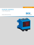
1
B E T R I E B S A N L E I T U N G / O P E R AT I N G I N S T R U C T I O N S DME5000 Entfernungs-Messgerät Distance Measuring Device D GB Betriebsanleitung DME5000 Dieses Werk ist urheberrechtlich geschützt. Die dadurch begründeten Rechte bleiben bei der Firma SICK AG. Eine Vervielfältigung des Werkes oder von Teilen dieses Werkes ist nur in den Grenzen der gesetzlichen Bestimmungen des Urheberrechtsgesetzes zulässig. Eine Abänderung oder Kürzung des Werkes ist ohne ausdrückliche schriftliche Zustimmung der Firma SICK AG untersagt. Inhalt/Contents 2 German Seite 2 – 72 English Page 73– 142 © SICK AG • Deutschland • Irrtümer und Änderungen vorbehalten 8009813/YHG5/2014-12 Betriebsanleitung Inhalt DME5000 Inhalt 1 Verwendete Symbole und Abkürzungen ......................................................................... 5 1.1 Typenschild ............................................................................................................ 5 2 Bestimmungsgemäße Verwendung ................................................................................ 6 3 Sicherheitshinweise .......................................................................................................... 7 3.1 Laserwarnhinweis ................................................................................................. 7 4 Funktionsweise.................................................................................................................. 8 5 Inbetriebnahme ................................................................................................................. 9 5.1 Montage ................................................................................................................. 9 5.1.1 Vorgehensweise bei der Ausrichtung ...............................................10 5.1.2 Anordnung benachbarter Entfernungs-Messgeräte........................11 5.1.3 Anordnung Entfernungs-Messgerät mit benachbarter Datenübertragung .............................................................................11 5.2 Elektrischer Anschluss ........................................................................................12 5.2.1 Verdrahtungshinweise ......................................................................14 5.2.2 PROFIBUS-Terminierung ...................................................................15 6 Bedienung ........................................................................................................................16 6.1 Aufbau des Bedienfeldes....................................................................................16 6.2 Bedienung ...........................................................................................................16 6.3 Bedienfeld ...........................................................................................................16 7 Menüstruktur ...................................................................................................................19 7.1 Flussdiagramm ....................................................................................................19 7.2 Erklärungen zur Menüstruktur ...........................................................................19 8 Beispiel .............................................................................................................................29 8.1 Parametereingabe am Beispiel „Code-Eingabe“ ...............................................29 9 Technische Daten ............................................................................................................31 9.1 Maßzeichnung .....................................................................................................31 9.2 Zubehör ...............................................................................................................32 9.2.1 Reflektoren ........................................................................................32 9.2.2 Stecker/Leitungen ............................................................................33 9.2.3 Befestigungstechnik .........................................................................39 9.2.4 Wetterschutzgehäuse .......................................................................39 9.2.5 Umlenkspiegel ...................................................................................40 9.2.6 Schnittstellenadapter .......................................................................40 9.2.7 Kühlgehäuse .....................................................................................41 9.3 Technische Daten DME5000-1xx ......................................................................42 9.4 Technische Daten DME5000-2xx ......................................................................43 9.5 Technische Daten DME5000-3xx ......................................................................44 10 Wartung ............................................................................................................................45 11 Troubleshooting ...............................................................................................................46 12 Begriffserklärungen ........................................................................................................49 ® 12.1 PROFIBUS ..........................................................................................................49 12.2 RS 422 .................................................................................................................49 12.3 SSI ........................................................................................................................50 12.4 DeviceNet ............................................................................................................50 12.5 Hiperface .............................................................................................................51 8009813/YHG5/2014-12 © SICK AG • Deutschland • Irrtümer und Änderungen vorbehalten 3 Inhalt Betriebsanleitung DME5000 13 Anhang ............................................................................................................................. 52 13.1 Preset .................................................................................................................. 52 13.2 PROFIBUS-Schnittstelle ...................................................................................... 54 13.2.1 Datenformat DME zu Master ........................................................... 54 13.2.2 Datenformat Master zu DME ........................................................... 55 13.2.3 Diagnosedaten (bei aktiviertem Parameter „Extended Diagnostics“) ..................................................................................... 55 ® 13.3 Inbetriebnahme DME5000 PROFIBUS (Beispiel Siemens Step 7) ................ 57 13.4 Schnittstellenadapter ......................................................................................... 58 13.5 Sleepmodus ........................................................................................................ 59 13.6 RS-422-Schnittstelle .......................................................................................... 59 13.6.1 Protokoll ............................................................................................ 60 13.6.2 Befehle .............................................................................................. 60 13.6.3 Beispiele für Befehle (Standard-Protokoll) ...................................... 61 13.7 DeviceNet-Schnittstelle ...................................................................................... 62 13.7.1 Allgemeines ....................................................................................... 62 13.7.2 Konfiguration .................................................................................... 62 13.7.3 Datenaustausch ............................................................................... 65 13.7.4 Polled Mode ...................................................................................... 65 13.7.5 Change of State Mode ...................................................................... 66 13.7.6 Parameter Offset und Preset ........................................................... 66 13.7.7 Sleepmodus (Laser aus) .................................................................. 67 13.7.8 Parameter im DME5000 speichern ................................................ 68 13.7.9 Zusätzliche Diagnosedaten .............................................................. 68 13.8 Hiperface-Schnittstelle ....................................................................................... 70 13.8.1 Typenspezifische Einstellung ........................................................... 71 13.8.2 Übersicht der unterstützen Befehle ................................................ 71 13.8.3 Übersicht der Hiperface-Standard-Statusmeldungen .................... 72 13.8.4 Verhalten bei Fehlern und Vorausfallmeldungen ........................... 72 4 © SICK AG • Deutschland • Irrtümer und Änderungen vorbehalten 8009813/YHG5/2014-12 Verwendete Symbole und Abkürzungen Betriebsanleitung Kapitel 1 DME5000 1 Verwendete Symbole und Abkürzungen Verweist auf die Tasten des Displays in der Maßzeichnung (Abschnitt 9.1 „Maßzeichnung“). Hinweis ACHTUNG Hinweise erläutern Vorteile bestimmter Einstellungen und helfen Ihnen, den optimalen Nutzen aus dem DME5000 zu ziehen. Warnhinweise: Lesen und befolgen Sie diese sorgfältig! Warnhinweise sollen Sie vor Gefahren schützen oder helfen Ihnen, eine Beschädigung des Sensors zu vermeiden. 1.1 Typenschild Anhand des Typenschildes kann der Gerätetyp, die Serien-Nummer des Gerätes und die Bestell-Nummer festgestellt werden. Hersteller Gerätetyp Bestell-Nummer Serien-Nummer Produktionsjahr/-monat 8009813/YHG5/2014-12 © SICK AG • Deutschland • Irrtümer und Änderungen vorbehalten 5 Kapitel 2 Bestimmungsgemäße Verwendung Betriebsanleitung DME5000 2 Bestimmungsgemäße Verwendung Das DME5000 ist ein optoelektronischer Sensor, der zum Erfassen von Distanzen zu einer linear bewegten Reflexionsfolie eingesetzt wird. Er darf nicht in explosionsgefährdeten Bereichen verwendet werden. 6 © SICK AG • Deutschland • Irrtümer und Änderungen vorbehalten 8009813/YHG5/2014-12 Betriebsanleitung Sicherheitshinweise Kapitel 3 DME5000 3 Sicherheitshinweise Lesen Sie die Betriebsanleitung vor der Inbetriebnahme. Anschluss, Montage und Einstellung nur durch Fachpersonal. Schützen Sie das DME5000 bei Inbetriebnahme vor Feuchte und Verunreinigung. Das DME5000 ist kein Sicherheitsmodul gemäß EU-Maschinenrichtlinie. Beachten Sie die nationalen Sicherheits- und Unfallverhütungsvorschriften. Reparaturen dürfen nur vom Hersteller durchgeführt werden. Eingriffe und Änderungen am Gerät sind unzulässig. Verdrahtungsarbeiten, Öffnen und Schließen von elektrischen Verbindungen nur im spannungslosen Zustand durchführen. 3.1 Laserwarnhinweis Verletzungsgefahr durch Laserstrahlung. Durch direktes Blicken in den Laserstrahl können die Augen geschädigt werden. Nicht in den Laserstrahl blicken. 8009813/YHG5/2014-12 © SICK AG • Deutschland • Irrtümer und Änderungen vorbehalten 7 Funktionsweise Kapitel 4 Betriebsanleitung DME5000 4 Funktionsweise Das Entfernungs-Messgerät DME5000 ist ein kompakter optischer Distanzsensor. Das DME wird so montiert, dass der ausgesendete Laserstrahl auf den Reflektor trifft. Der Reflektor oder das Gerät bewegen sich entlang des Laserstrahls. Der Empfänger des DME empfängt das vom Reflektor zurückgespiegelte Licht und ermittelt die Distanz zwischen Sensor und Reflektor mittels Lichtlaufzeitmessung. Die gemessene Distanz wird, je nach Gerätevariante, über eine SSI-, RS-422-, DeviceNet-, Hiperface- oder PROFIBUS-Schnittstelle an eine Steuerung oder einen Lageregelkreis übertragen. Durch die schnelle Messwertermittlung ist das DME5000 für den direkten Betrieb in einem geschlossenen Lageregelkreis über die SSI-Schnittstelle z. B. mit einem Frequenzumrichter geeignet. Abb. 1: Funktionsweise DME5000 8 © SICK AG • Deutschland • Irrtümer und Änderungen vorbehalten 8009813/YHG5/2014-12 Betriebsanleitung Inbetriebnahme Kapitel 5 DME5000 5 Inbetriebnahme 5.1 Montage Das DME5000 und der Reflektor werden so befestigt, dass der Reflektor immer im Sichtfeld des Sensors ist. Das DME5000 wird so ausgerichtet, dass sich der (auch in großen Abständen) gut sichtbare Lichtfleck im Zentrum des Reflektors befindet. Die als Zubehör erhältliche Ausrichthalterung ermöglicht eine einfache Justierung in X- und Y-Richtung: Abb. 2: Justage DME5000 Die Reflektorgröße ist so zu wählen, dass der Lichtfleck bei Vibrationen nicht vom Reflektor abwandert. Ist der Reflektor am bewegten Teil befestigt, ist in der Regel eine kleinere Reflexionsfolie ausreichend. Bei hochglänzenden Oberflächen (z. B. Regalprofile, Paletten mit Stretchfolien, Fahrschienen), die den Lichtstrahl oder Streulicht einspiegeln, Reflektor in den „freien Raum“ ausrichten: mit ca. 1°… 3° Neigung (X- oder Y-Richtung) montieren. Verschiedene Reflektorgrößen siehe Abschnitt 9.2 „Zubehör“ (ab Seite 32). Abb. 3: Justage DME5000 bei hochglänzender Umgebung 8009813/YHG5/2014-12 © SICK AG • Deutschland • Irrtümer und Änderungen vorbehalten 9 Inbetriebnahme Kapitel 5 Betriebsanleitung DME5000 5.1.1 Vorgehensweise bei der Ausrichtung Bringen Sie Fahrzeug und Reflektor auf kleine Distanz. Richten Sie das DME5000 so aus, dass der Lichtfleck sich im Zentrum des Reflektors befindet. Vergrößern Sie die Entfernung von Fahrzeug zu Reflektor und beobachten Sie dabei den Lichtfleck. Justieren Sie gegebenenfalls den Lichtfleck in die Mitte des Reflektors nach. Die im Display-Infofeld 1 angezeigte Signaldämpfung gibt Aufschluss über das aktuelle Empfangssignal. Bei sauberen Grenzflächen sollten die in der Tabelle aufgeführten Dämpfungswerte nicht überschritten werden. Tab. 1: Dämpfungswerte 10 DME5000 -1XX -2XX -3XX Distanz [m] Pegel [dB] Pegel [dB] Pegel [dB] 13 –42 –42 –42 15 –43 –43 –43 20 –50 –47 –46 30 –57 –54 –53 40 –62 –59 –58 50 –66 –63 –62 60 –69 –66 –65 70 –71 –69 –68 80 –71 –70 90 –73 –72 100 –75 –74 110 –77 –76 120 –78 –77 130 –80 –79 140 –81 –80 150 –82 –81 160 –82 170 –83 180 –84 190 –85 200 –86 210 –87 220 –88 230 –89 240 –89 250 –90 260 –91 270 –91 280 –92 290 –93 300 –93 © SICK AG • Deutschland • Irrtümer und Änderungen vorbehalten 8009813/YHG5/2014-12 Betriebsanleitung Inbetriebnahme Kapitel 5 DME5000 5.1.2 Anordnung benachbarter Entfernungs-Messgeräte Um gegenseitige Beeinflussung zu vermeiden, sind folgende Mindestabstände a einzuhalten. Abb. 4: Anordnung benachbarter DME5000 Parallelmontage a ≥ 100 mm + 0,01 x smax. [mm] DME Reflektor Reflektor DME Reflektor Antiparallele Montage a ≥ 100 mm DME DME Reflektor 5.1.3 Anordnung Entfernungs-Messgerät mit benachbarter Datenübertragung Abb. 5: Anordnung benachbarter DME5000 und ISD Reflektor DME ISD ISD Für die Datenübertragungs-Lichtschranken der Baureihe ISD300 / ISD400-1xxx / ISD4006xxx ist unabhängig von der maximalen Reichweite smax ein minimaler Strahlabstand von 100 mm einzuhalten. 8009813/YHG5/2014-12 © SICK AG • Deutschland • Irrtümer und Änderungen vorbehalten 11 Inbetriebnahme Kapitel 5 Betriebsanleitung DME5000 5.2 Elektrischer Anschluss DME5000 nach Anschlussschema anschließen. Verdrahtungshinweise beachten (siehe Abschnitt 5.2.1), Stecker und Kabel siehe Abschnitt 9.2.2. Abb. 6: Anschlussschema DME5000-xx1 (SSI) DME5000-xx3 (RS 422) Abb. 7: Anschlussschema ® DME5000-xx2 (PROFIBUS ) 12 © SICK AG • Deutschland • Irrtümer und Änderungen vorbehalten 8009813/YHG5/2014-12 Betriebsanleitung Inbetriebnahme Kapitel 5 DME5000 Abb. 8: Anschlussschema DME5000-xx4 (DeviceNet) Abb. 9: Anschlussschema DME5000-xx5 (DeviceNet) Abb. 10: Anschlussschema DME5000-xx7 (Hiperface) 8009813/YHG5/2014-12 © SICK AG • Deutschland • Irrtümer und Änderungen vorbehalten 13 Inbetriebnahme Kapitel 5 Betriebsanleitung DME5000 5.2.1 ACHTUNG Verdrahtungshinweise Es werden generell abgeschirmte Leitungen für Versorgung und Schnittstelle empfohlen (siehe Abschnitt 9.2 „Zubehör“). Ein einwandfreies und vollständiges Schirmkonzept ist für die störungsfreie Funktion erforderlich. Speziell muss auf die beidseitige Auflage des Kabelschirmes an Schaltschrank und DME5000 geachtet werden. Der Kabelschirm der vorkonfektionierten M16-Kabel ist mit dem Metallstecker und damit mit dem DME5000-Gehäuse verbunden. Der Kabelschirm am Schaltschrank muss großflächig mit der Betriebserde verbunden werden. Potenzialausgleichströme über den Kabelschirm sind durch geeignete Maßnahmen zu vermeiden. Eine störsichere Datenübertragung ist nur bei Verwendung von abgeschirmten Leitungen mit paarweise verdrillten Adern gegeben. Die Schirme der PROFIBUS-Leitungen sind über die PROFIBUS-Stecker miteinander verbunden. Legende Kabelgruppen Abbildung 11 bis Abbildung 13: 1 = sehr störempfindliche Leitungen (analoge Messleitungen) 2 = störempfindliche Leitungen (Sensorkabel, Kommunikationssignale, Busleitungen) 3 = Störquellen-Leitung (Steuerkabel für induktive Lasten, Motorbremsen) 4 = stark störende Leitungen (Ausgangskabel von Frequenzumrichtern, Versorgung von Schweißanlagen, Leistungskabel) Abb. 11: Leitungen der Gruppe 1, 2 und 3, 4 rechtwinklig kreuzen Abb. 12: Ideal: Leitungen in verschiedenen Kabelkanälen verlegen Abb. 13: Alternativ: Leitungen durch metallischen Trennsteg trennen 14 © SICK AG • Deutschland • Irrtümer und Änderungen vorbehalten 8009813/YHG5/2014-12 Betriebsanleitung Inbetriebnahme Kapitel 5 DME5000 Abb. 14: Keine „Schweineschwänzchen“, Schirm kurz und vollflächig anbinden, BEIDE Seiten erden Abb. 15: Schirmanschluss bei Kunststoffgehäusen 5.2.2 PROFIBUS-Terminierung Abb. 16: PROFIBUSTerminierung (siehe Zubehör Abschnitt 9.2.2) Terminator 8009813/YHG5/2014-12 © SICK AG • Deutschland • Irrtümer und Änderungen vorbehalten 15 Bedienung Kapitel 6 Betriebsanleitung DME5000 6 Bedienung Dieses Kapitel erklärt das Bedienfeld und die grundsätzliche Bedienung des DME5000. Detaillierte Informationen zur Inbetriebnahme und zum Betrieb des DME5000 finden Sie im Kapitel 5 „Inbetriebnahme“. 6.1 Aufbau des Bedienfeldes Abb. 17: Display LC-Display Funktionstasten Das Bedienfeld ist in zwei Bereiche unterteilt: LC-Display: Zeigt das Menü während der Parametrierung Funktionstasten: Zur Eingabe der Parameter bzw. Funktionen 6.2 Bedienung Das DME5000 ist mit einer Folientastatur ausgestattet. ACHTUNG Bedienen Sie den Eingabebereich nur mit den Fingern oder mit einem geeigneten Zeigegerät! Benutzen Sie keine spitzen oder harten Gegenstände. Sie können die Funktionstasten beschädigen und die Bedienung damit erschweren oder unmöglich machen. 6.3 Bedienfeld Nach Anlegen der Betriebsspannung (oder nach Reset) erscheint folgende Anzeige im Display des DME5000: Abb. 18: Anzeige nach Anlegen der Betriebsspannung Infofeld 1 Statusanzeigen Infofeld 2 Funktionstasten Nach ca. 1 s ist das DME5000 betriebsbereit und zeigt, bei freier Sicht auf den Reflektor, den aktuellen Messwert an: 16 © SICK AG • Deutschland • Irrtümer und Änderungen vorbehalten 8009813/YHG5/2014-12 Betriebsanleitung Bedienung Kapitel 6 DME5000 Abb. 19: Messwertanzeige Statusanzeigen Anzeige Bedeutung Wird angezeigt Wird nicht angezeigt MF1 Multifunktionsein-/ausgang Ein-/Ausgang aktiv Ein-/Ausgang nicht aktiv MF2 Multifunktionsausgang Ausgang aktiv Ausgang nicht aktiv TMP Geräteinnentemperatur Vorausfallmeldung: Geräteinnentemperatur im Grenzbereich Geräteinnentemperatur OK ATT Verschmutzung Vorausfallmeldung: Empfangssignalpegel im Grenzbereich Empfangspegel OK LSR Laser Vorausfallmeldung Messlaser Laser OK PLB Plausibilität Messfehler Ursache: z. B. Lichtstrahlunterbrechung, Verschmutzung, Optische/elektrische Störeinflüsse Messwert OK RDY Betriebsbereit (Ready) Bei Betriebsbereitschaft Initialisierung, Hardwaredefekt BUS Schnittstelle: Clocksignal empfangen Telegrammverkehr Telegrammverkehr Continuous mode ‒ Kein Clock-Signal Kein Telegrammverkehr Kein Telegrammverkehr Request mode Unabhängig vom Busstatus SSI ® PROFIBUS DeviceNet RS 422 Hiperface Abhilfemaßnahmen bei Fehlermeldungen/Vorausfallmeldungen siehe Kapitel 11 „Troubleshooting“. 8009813/YHG5/2014-12 © SICK AG • Deutschland • Irrtümer und Änderungen vorbehalten 17 Kapitel 6 Bedienung Betriebsanleitung DME5000 Infofeld 1 (Beispiel) – 65 dB Empfangspegel: Aktuelle Signaldämpfung Ver. 1.0 Software-Version 3.3.3.1 Menüunterpunkt (siehe Menüübersicht), Parameteränderungen nicht möglich. 3.3.3.1 ! „!“: Code richtig eingegeben: Parameteränderungen möglich. 3.3.3.1 ? „?“: Eingegebener Parameter ist ungültig, vorher gültiger Parameter bleibt gespeichert. Ursache: z. B. unteres Schaltlimit > oberes Schaltlimit. Abhilfe: Parameter korrigieren. Infofeld 2 (Beispiel) + 010.000 m Aktueller Messwert, wird bei Messbetrieb angezeigt. Code Menüpunkte und Parameter werden hier angezeigt. „Code“ erscheint durch Drücken von Service . Blinkende Anzeige Service signalisiert einen Hardwaredefekt oder Über-/Untertemperatur. Tasten Führt durch die Menüstruktur, Code, Parametereingabe, Speichern von Parametern. Verlassen eines Menüunterpunktes. Auswahl von Menüpunkten, Eingabe von Zahlen 18 © SICK AG • Deutschland • Irrtümer und Änderungen vorbehalten 8009813/YHG5/2014-12 Menüstruktur Betriebsanleitung Kapitel 7 DME5000 7 Menüstruktur 7.1 Flussdiagramm Auf der Innenseite der hinteren Umschlagklappe ist die Menüstruktur des DME5000 in Form eines Flussdiagramms dargestellt. Klappen Sie diese Seite aus, um sich während der folgenden Erklärungen besser in der Menüstruktur zurechtzufinden. 7.2 Erklärungen zur Menüstruktur Code Schutz vor unbeabsichtigtem Verändern der eingestellten Parameter. Code: 314 Funktion: Menüzugang und Verändern der Parameter: Code 314 bestätigen mit . Die erfolgreiche Eingabe des Codes wird im Display mit einem „!“ bestätigt. Parameteränderungen, die mit gespeichert. Hinweis bestätigt werden, sind sofort aktiv und nichtflüchtig Während der Parameteränderung muss der Reflektor im Sichtfeld des Sensors sein. Es darf keine Buskommunikation aktiv sein. Änderungen der Busadresse sind erst nach einem Geräteneustart aktiv. Wird die Eingabe des Code übersprungen oder eine andere Zahl (als 314) eingegeben, werden die gültigen Parameter im Display angezeigt, ein Ändern ist dann nicht möglich. Hinweis Die Möglichkeit alle Parameter ohne Änderungsmöglichkeit einzusehen erleichtert z. B. die Abfrage und Übermittlung von Parametern durch ungeschultes Personal. Software-Version z. B. „Ver. 1.0“ Parameter Je nach Gerätevariante wird hier die Schnittstelle, der Multifunktions-Ein-/Ausgang MF1, der Ausgang MF2, die Auflösung und ein Offset eingestellt. Ein Reset stellt alle Parameter auf Default zurück. Hinweis 8009813/YHG5/2014-12 Bei PROFIBUS-Geräten sollten bei Verwendung des gsd-Moduls „Class 2“ die Parameter nicht über das Display eingestellt werden, da diese bei erneutem „Hochfahren“ des PROFIBUS vom PROFIBUS-Master mit den in der Steuerung hinterlegten Parametern überschrieben werden. Ausnahme: PROFIBUS-Adresse und Offset bei aktivierter Preset-Funktion. © SICK AG • Deutschland • Irrtümer und Änderungen vorbehalten 19 Kapitel 7 Menüstruktur Betriebsanleitung DME5000 Interface Je nach Gerätetyp erscheint im Menü nur die jeweilige Schnittstelle des Gerätetyps. SSI Funktion SSI-Schnittstelle siehe Kapitel 12 „Begriffserklärungen – SSI“. Coding Binary Gray (Default) Messwertausgabe im Binärcode Messwertausgabe im Gray-Code Mode Datenformat Binär Gray 25 bit (default) Messwert: Bit 1 ... 24 LSB: Plausibilitätsbit Messwert inkl. Plausibilitäts-Bit im GrayCode eincodiert 24 bit + err Messwert: Bit 1 ... 24 LSB: Plausibilitätsbit Messwert: Bit 1 ... 24 LSB: Plausibilitätsbit 24 bit Messwert: Bit 0 ... 23 Messwert: Bit 0 ... 23 Plausibilitätsbit: 0: OK 0: OK 1: Plausibilitätsfehler 1: Plausibilitätsfehler Activation On (default) SSI-Schnittstelle in Betrieb, RS-422-Schnittstelle nicht in Betrieb. Off RS-422-Schnittstelle in Betrieb, SSI-Schnittstelle nicht in Betrieb. Die RS-422-Schnittstelle ermöglicht das Parametrieren des DME mit dem Schnittstellenadapter (siehe Abschnitt 13.4 „Schnittstellenadapter“). (Baudrate und Protokoll unter > 3.2 Serial < einstellen) Monitor On Serielle Monitorschnittstelle in Betrieb, Multifunktionsausgänge MF1 und MF2 nicht in Betrieb. Ermöglicht das Parametrieren des DME5000 mit dem Schnittstellenadapter (siehe Abschnitt 13.4 „Schnittstellenadapter“) bzw. das Mithören von Messwerten über MF1 und MF2 während des SSI-Betriebs. Die eingeschaltete Monitorschnittstelle wird im Menü 3.3.2 und 3.4.2 MF-Function mit „Monitor“ angezeigt. Die SSI-Schnittstelle ist voll funktionsfähig (Baudrate und Protokoll unter > 3.2 Serial < einstellen). Off (default) Multifunktionsausgänge MF1 und MF2 in Betrieb, wie unter Punkt 3.3/3.4 eingestellt. ® PROFIBUS 20 © SICK AG • Deutschland • Irrtümer und Änderungen vorbehalten 8009813/YHG5/2014-12 Menüstruktur Betriebsanleitung Kapitel 7 DME5000 Profile Encoder Dieses Profil entspricht dem Standard-Encoder-Profil, Beschreibung siehe Abschnitt 13.2 „PROFIBUSSchnittstelle“. SICK (default) Dieses Profil basiert auf dem Standard-Encoder-Profil. Zusätzlich zum Messwert werden Warn-, Zustands- und Fehlerinformationen übertragen. Beschreibung siehe Abschnitt 13.2 „PROFIBUSSchnittstelle“. Bus Address Addr. 006 (default) Hinweis Hier wird die PROFIBUS-Teilnehmeradresse eingestellt. (001 … 125) Inbetriebnahme-Beispiel mit Siemens Step 7 siehe Kapitel 13 „Anhang“. Hiperface BusAddress Add 00 (default) Einstellung der Hiperface-Adresse (Bereich 0 … 31) Baudrate Einstellung der Baudrate 0,6 kBd 1,2 kBd 2,4 kBd 4,8 kBd 9,6 kBd (default) 19,2 kBd 38,4 kBd Data 8, o, 1 8-Datenbit, ungerade Parität, 1 Stopbit 8, e, 1 (default) 8-Datenbit, gerade Parität, 1 Stopbit 8, n, 1 8-Datenbit, keine Parität, 1 Stopbit Timeout X1 1*11/Baudrate X4 (default) 4*11/Baudrate Monitor 8009813/YHG5/2014-12 On Serielle Monitorschnittstelle in Betrieb, Multifunktionsausgänge MF1 und MF2 nicht in Betrieb. Ermöglicht das Parametrieren des DME5000 mit dem Schnittstellenadapter (siehe Abschnitt 13.4 „Schnittstellenadapter“) bzw. das Mithören von Messwerten über MF1 und MF2. Off (default) Multifunktionsausgänge MF1 und MF2 in Betrieb, wie unter Punkt 3.3/3.4 eingestellt. © SICK AG • Deutschland • Irrtümer und Änderungen vorbehalten 21 Menüstruktur Kapitel 7 Betriebsanleitung DME5000 Period Len Hinweis 1 Typecode 90H (default) Entspr. Auflösung 1 mm pro Periode 2 Typecode 91H Entspr. Auflösung 2 mm pro Periode 4 Typecode 92H Entspr. Auflösung 4 mm pro Periode 8 Typecode 93H Entspr. Auflösung 8 mm pro Periode 16 Typecode 94H Entspr. Auflösung 16 mm pro Periode Für eine detaillierte Beschreibung siehe Abschnitt 13.8 „Hiperface-Schnittstelle“. RS 422 Mode Request Datenübertragung nur auf Anforderung Continuous Zyklische Datenübertragung gemäß der eingestellten Baudrate Protocol Hinweis Standard <STX>8122<[sign]><7*[0…9]><ETX> CRLF <[sign]><7*[0…9]><CR><LF> CP0 <[sign]><7*[0…9]> CP1 Nicht belegt Für eine detaillierte Beschreibung siehe Abschnitt 13.6 „RS-422-Schnittstelle“. DeviceNet Baudrate 125 (default) Einstellung der Baudrate (125, 250, 500 kBd) Bus Address Addr. 06 (default) Hinweis Einstellung der DeviceNet-Adresse (Bereich 0 ... 63) Für eine detaillierte Beschreibung siehe Abschnitt 13.7 „DeviceNet-Schnittstelle“. Serial Baudrate 19,2 (default) Baudrate für RS-422-Schnittstelle (max. 115,2 kBd) Baudrate für Monitor-Schnittstelle über MF1 und MF2 (max. 38,44 kBd), nur bei DME5000 mit SSI- bzw. Hiperface-Schnittstelle Genaue Beschreibung siehe Abschnitt 13.4 „Schnittstellenadapter – Monitor-Mode“. Data 22 7,e,1 7-Datenbit, gerade Parität, 1 Stopbit 8,e,1 8-Datenbit, gerade Parität, 1 Stopbit 8,n,1 (default) 8-Datenbit, keine Parität, 1 Stopbit © SICK AG • Deutschland • Irrtümer und Änderungen vorbehalten 8009813/YHG5/2014-12 Betriebsanleitung Menüstruktur Kapitel 7 DME5000 MF1 Parametrierbarer Aus- oder Eingang Act.State Parametrierung der Schaltlogik bei MF1 = Ausgang Active 1 (default) HIGH-Pegel bei aktivem Ausgang (Schließer/NO) Active 0 LOW-Pegel bei aktivem Ausgang (Öffner/NC) Parametrierung der Schaltlogik bei MF1 = Eingang Active 1 (default) Aktivierung Eingang bei steigender Flanke Active 0 Aktivierung Eingang bei fallender Flanke Function (default) MF1 wird als Distanzschaltausgang verwendet, siehe 3.3.3. Service MF1 wird als Serviceausgang verwendet, siehe 3.3.4. Sleepmodus MF1 wird als Eingang für die Aktivierung des Sleepmodus (Laser aus) verwendet, Quittierung über Ready-Status Funktionsbeschreibung siehe Abschnitt 13.5 „Sleepmodus“. Preset MF1 wird als Eingang für die Aktivierung des Preset (Überschreiben des Offset) verwendet. Offset = Presetwert - aktueller Messwert Funktionsbeschreibung siehe Abschnitt 13.1 „Preset“. SPEED MF1 wird als Geschwindigkeitsschaltausgang verwendet, siehe 3.3.5. Monitor (nur bei SSI- bzw. Hiperface-Variante): Wird angezeigt, wenn unter 3.1.4, bzw. 3.1.5 die Monitorschnittstelle ON gesetzt wird. Distance Distance MF1 wird als Distanzschaltausgang verwendet. Aktiv bei Überschreitung von „UpperLimit“. Inaktiv bei Unterschreitung von „LowerLimit“. 8009813/YHG5/2014-12 © SICK AG • Deutschland • Irrtümer und Änderungen vorbehalten 23 Kapitel 7 Menüstruktur Betriebsanleitung DME5000 Service Sammelausgang für frei einstellbare Statusmeldungen in „ODER“-Verknüpfung, die Aufschluss über den Gerätezustand geben. Laser Level UpperTemp LowerTemp Aktiv Nicht Aktiv On (default) Vorausfallmeldung Laser OK Off – On (default) Vorausfallmeldung Off – On (default) ÜbertemperaturÜberwachung: Laserdiode Nicht verschmutzt Verschmutzung Geräteinnentemperatur > oberes eingestelltes Temperaturlimit Off – On (default) UntertemperaturÜberwachung: Geräteinnentemperatur < unteres eingestelltes Temperaturlimit Off – On Fehlerhafter Messwert Geräteinnentemperatur < oberes eingestelltes Temperaturlimit Geräteinnentemperatur > unteres eingestelltes Temperaturlimit Messwert OK Ursache: Plausib(ility) – z. B. Lichtstrahlunterbrechung – Verschmutzung – optische/elektrische Störeinflüsse Ready Off – On (default) Initialisierung, Hardwarefehler, Laser ausgeschaltet Off – On Busfehler Datenübertragung OK SSI: kein Clocksignal Bus Status PB/DN: kein Telegrammverkehr RS 422/Hiperface: ‒ Off (default) 24 Betriebsbereit, Messwert OK RS 422/Hiperface: unabhängig vom Busstatus – © SICK AG • Deutschland • Irrtümer und Änderungen vorbehalten 8009813/YHG5/2014-12 Betriebsanleitung Menüstruktur Kapitel 7 DME5000 Speed MF1 wird als Geschwindigkeitsschaltausgang verwendet. Aktiv bei Überschreitung von „Limit“. Die Schalthysterese ist fix ± 0,1 m/s. Limit Sign Aktiv Nicht aktiv Range 0,0 … 9,9 m/s Geschwindigkeit > Limit Geschwindigkeit < Limit +/– Überwachung in beide Verfahrrichtungen + Überwachung in Verfahrrichtung „+“ (zunehmende Distanz) – Überwachung in Verfahrrichtung „–“ (abnehmende Distanz) MF2 Parametrierbarer Ausgang Active State Parametrierung der Schaltlogik Active 1 HIGH-Pegel bei aktivem Ausgang (Schließer/NO) Active 0 LOW-Pegel bei aktivem Ausgang (Öffner/NC) Function Distance siehe 3.4.3 MF2 wird als Distanzschaltausgang verwendet. Service (default) siehe 3.4.4 MF2 wird als Serviceausgang verwendet. Speed siehe 3.4.5. MF2 wird als Geschwindigkeitsschaltausgang verwendet. Monitor (nur bei SSI- bzw. Hiperface-Variante): Wird angezeigt, wenn unter 3.1.4, bzw. 3.1.5 die Monitorschnittstelle ON gesetzt wird. Distance MF2 wird als Distanzschaltausgang verwendet. Aktiv bei Überschreitung von „UpperLimit“. Inaktiv bei Unterschreitung von „LowerLimit“. 8009813/YHG5/2014-12 © SICK AG • Deutschland • Irrtümer und Änderungen vorbehalten 25 Kapitel 7 Menüstruktur Betriebsanleitung DME5000 Service Sammelausgang für frei einstellbare Statusmeldungen in „ODER“-Verknüpfung, die Aufschluss über den Gerätezustand geben. Laser Level UpperTemp LowerTemp Plausib(ility) Aktiv Nicht aktiv On (default) Vorausfallmeldung Vorausfallmeldung Laserdiode Laserdiode Off – On (default) Vorausfallmeldung Off – On (default) ÜbertemperaturÜberwachung: Nicht verschmutzt Verschmutzung Geräteinnentemperatur > oberes eingestelltes Temperaturlimit Off – On (default) UntertemperaturÜberwachung: Geräteinnentemperatur < unteres eingestelltes Temperaturlimit Off – On (default) Fehlerhafter Messwert, Messwertausgabe „0“ Geräteinnentemperatur < oberes eingestelltes Temperaturlimit Geräteinnentemperatur > unteres eingestelltes Temperaturlimit Messwert OK Ursache: – z. B. Lichtstrahlunterbrechung – Verschmutzung – optische/elektrische Störeinflüsse Ready Off – On (default) Initialisierung Betriebsbereit, Hardwarefehler, Messwert OK Messfehler, Laser ausgeschaltet Bus Status Off – On Busfehler SSI: kein Clocksignal PB/DN: kein Telegrammverkehr RS 422/Hiperface: – 26 Datenübertragung OK © SICK AG • Deutschland • Irrtümer und Änderungen vorbehalten RS 422/Hiperface: unabhängig vom Busstatus 8009813/YHG5/2014-12 Menüstruktur Betriebsanleitung Kapitel 7 DME5000 Aktiv Off (default) Nicht aktiv – Speed MF2 wird als Geschwindigkeitsschaltausgang verwendet. Aktiv bei Überschreitung von „Limit“. Die Schalthysterese ist fix ± 0,1 m/s. Limit Sign Aktiv Nicht aktiv Range 0,0 … 9,9 m/s Geschwindigkeit > Limit Geschwindigkeit < Limit +/– Überwachung in beide Verfahrrichtungen + Überwachung in Verfahrrichtung „+“ (zunehmende Distanz) – Überwachung in Verfahrrichtung „–“ (abnehmende Distanz) Resolution Einstellung der Auflösung wirkt ausschließlich auf die digitalen Datenschnittstellen. Bei der Hiperface-Variante darf dieser Parameter nicht geändert werden. Eine Veränderung der Auflösung erfolgt dort über den Parameter 3.1.6 „Period Length“. Einstellbar: 50 ... 5000 µm, default 100 µm (bzw. 125 µm bei Hiperface-Variante) Offset Der Offsetwert wird zum intern ermittelten DME-Messwert addiert und wirkt auf alle Ausgänge und das Display. Einstellbar: ± 250 m Hinweis Über die SSI-Schnittstelle wird bei negativem Messwert „0“ ausgegeben. Hinweis Bei aktivierter Preset-Funktion wird der Offsetwert durch Auslösen des Preset-Eingangs überschrieben, siehe auch Abschnitt 13.1 „Preset“. Plausibilität Diese Funktion überwacht Messwerte auf Plausibilität. Spricht an bei Lichtstrahlunterbrechung, Verschmutzung oder optischen/elektrischen Störungen. Plausibilitätsfehler führt zu Messwertausgabe 0. 8009813/YHG5/2014-12 200 ms (Default) Normal Off Fehlerunterdrückung durch Messwertextrapolation für max. 200 ms; bei Fehler > 200 ms Fehlerausgabe Fehlerunterdrückung für 1 internen Messzyklus, bei länger anliegendem Fehler erfolgt keine Überprüfung auf Plausibilität, Fehlerausgabe erfolgt nur dann, wenn keine Messung © SICK AG • Deutschland • Irrtümer und Änderungen vorbehalten 27 Kapitel 7 Menüstruktur Betriebsanleitung DME5000 Fehlerausgabe. mehr möglich ist. Temperatur Anzeige der aktuellen Geräteinnentemperatur. Reset 28 NO YES Kein Reset Rückstellung auf Default-Werte © SICK AG • Deutschland • Irrtümer und Änderungen vorbehalten 8009813/YHG5/2014-12 Beispiel Betriebsanleitung Kapitel 8 DME5000 8 Beispiel 8.1 Hinweis Parametereingabe am Beispiel „Code-Eingabe“ Alle Parameter lassen sich auf diese Art und Weise einstellen. Während der Parameteränderung muss der Reflektor im Sichtfeld des Sensors sein. Schritt 1 Legen Sie die Betriebsspannung an. Anzeige Schritt 2 Rufen Sie mit das Menü „CODE“ auf. Anzeige Schritt 3 Rufen Sie mit das Eingabefeld „CODE 000“ auf. Die 1. Ziffer blinkt. Anzeige Schritt 4 Drücken Sie 3 x für das Passwort „000“ (nur Parameteransicht) oder geben Sie mit die gewünschte 1. Ziffer (z. B. „3“) ein. Anzeige 8009813/YHG5/2014-12 © SICK AG • Deutschland • Irrtümer und Änderungen vorbehalten 29 Beispiel Kapitel 8 Betriebsanleitung DME5000 Schritt 5 Gehen Sie mit eine Stelle weiter und geben Sie mit die gewünschte 2. Ziffer (z. B. „1“) ein. Anzeige Schritt 6 Gehen Sie mit eine Stelle weiter und geben Sie mit die gewünschte 3. Ziffer (z. B. „4“) ein. Anzeige Schritt 7 Drücken Sie , um die 3. Ziffer „4“ zu bestätigen. Anzeige Hinweis 30 Das Ausrufezeichen „!“ im Display bestätigt: Parametriermode. © SICK AG • Deutschland • Irrtümer und Änderungen vorbehalten 8009813/YHG5/2014-12 Betriebsanleitung Technische Daten Kapitel 9 DME5000 9 Technische Daten 9.1 Maßzeichnung Gerätenullpunkt Abb. 20: Maßzeichnung DME5000 Abb. 21: Maßzeichnungen Rückansicht DME5000 DME5000-xx1 DME5000-xx3 1 x M16-Stecker (SSI/RS 422) DME5000-xx2 DME5000-xx4 DME5000-xx7 1 x M16-/2 x M12 1 x M16-/1 x M12® Stecker (PROFIBUS ) Stecker (DeviceNet) 2 x M12-Stecker (Hiperface) DME5000-xx5 1 x M12-Stecker (DeviceNet) Abb. 22: Maßzeichnung DME5000 am Halter montiert 8009813/YHG5/2014-12 © SICK AG • Deutschland • Irrtümer und Änderungen vorbehalten 31 Technische Daten Kapitel 9 Betriebsanleitung DME5000 9.2 Zubehör 9.2.1 Reflektoren 2 Reflektor 0,3 x 0,3 m Diamond Grade, montiert Typ: PL240DG Bestell-Nr.: 1017910 2 Reflektor 1 x 1 m Diamond Grade, montiert Typ: PL880DG 1) 1) 2 Reflektor 0,6 x 0,6 m Diamond Grade, montiert Typ: PL560DG 1) Bestell-Nr.: 1016806 1) Bestell-Nr.: 1018975 Grundplatte: ALMG3 32 © SICK AG • Deutschland • Irrtümer und Änderungen vorbehalten 8009813/YHG5/2014-12 Technische Daten Betriebsanleitung Kapitel 9 DME5000 2 2 Reflektor 0,3 x 0,3 m Diamond Grade, geregelte Heizung +20 °C 1) AC 230 V/200 W, IP 64 Reflektor 0,6 x 0,6 m Diamond Grade, geregelte Heizung +20 °C 1) AC 230 V/900 W, IP 64 Typ: PL240DG-H Typ: PL560DG-H Bestell-Nr.: 1022926 Bestell-Nr.: 1023888 Reflexionsfolie Diamond Grade, Größe konfektionierbar Reflexionsfolie Diamond Grade, Bogen 749 x 914 mm Typ: REF-DG- Typ: REF-DG Bestell-Nr.: 4019634 9.2.2 2 Bestell-Nr.: 5320565 Stecker/Leitungen ® PROFIBUS , SSI, RS 422 und DeviceNet (nur DME5000-xx4) Leitungsdose M16, 8-polig, gerade, geschirmt Leitungsdose M16, 8-polig, gewinkelt, geschirmt Typ: DOS-1608-GA Typ: DOS-1608-WA Bestell-Nr.: 6025726 Steckeransicht 1) Bestell-Nr.: 6025727 Steckeransicht Grundplatte: ALMG3 8009813/YHG5/2014-12 © SICK AG • Deutschland • Irrtümer und Änderungen vorbehalten 33 Technische Daten Kapitel 9 Betriebsanleitung DME5000 Leitungsdose M16, 8-polig, gerade, 5 m/50 m, geschirmt Leitungsdose M16, 8-polig, gerade, 10 m, geschirmt Typ: DOL-1608-G05MA Bestell-Nr.: 2026742 Typ: DOL-1608-G10MA Typ: DOL-1608-G50MA Bestell-Nr.: 6032903 Bestell-Nr.: 2027193 Steckeransicht Leitungsdose M16, 8-polig, gewinkelt, 5 m, geschirmt Leitungsdose M16, 8-polig, gewinkelt, 10 m, geschirmt Typ: DOL-1608-W05MA Typ: DOL-1608-W10MA Bestell-Nr.: 2026743 Bestell-Nr.: 2027194 Steckeransicht 2 2 Leitung 2 x 0,5 mm , 6 x 0,25 mm , Technische Daten paarweise verdrillt, abgeschirmt Typ: LTG-2308-MW Bestell-Nr.: 6026292 Temperaturbereich bewegt –5 ... +70 °C festverlegt –40 ... +80 °C Mantel PUR kieselgrau Schirm verzinntes Kupfergeflecht Legende: 1 = Adernpaar blk/wht 2 = Adernpaar red/vio 3 = Adernpaar pnk/gra 4 = Adernpaar brn/blu 5 = Isolierfolie 6 = Schirm 7 = PUR-Mantel 34 © SICK AG • Deutschland • Irrtümer und Änderungen vorbehalten 8009813/YHG5/2014-12 Betriebsanleitung Technische Daten Kapitel 9 DME5000 ® PROFIBUS ® PROFIBUS Abschlusswiderstand, M12, B-cod. Bus in, Leitungsdose, M12, 5-polig, B-cod., geschirmt Typ: PR-STE-END Typ: PR-DOS-1205-G Bestell-Nr.: 6021156 Bestell-Nr.: 6021353 2 Bus out, Leitungsstecker, M12, 5-polig, B-cod., geschirmt PROFIBUS-Leitung, 2 x 0,34 mm , Meterware Typ: PR-STE-1205-G Typ: LTG-2102-MW Bestell-Nr.: 6021355 Temperaturbereich bewegt –5 ... +80 °C Bestell-Nr.: 6021354 Festverlegt –40 ... +80 °C Mantel PUR violett Ø 8 mm Schirm AL-PT-Folie Bus in, Leitungsdose mit PROFIBUS-Leitung, 5 m, B-cod. Bus in, Leitungsdose mit PROFIBUS-Leitung, 10 m, B-cod. Typ: DOL-12PR-G05 Typ: DOL-12PR-G10 Bestell-Nr.: 6026006 Bestell-Nr.: 6026008 Bus out, Leitungsstecker mit PROFIBUS-Leitung, 5 m, B-cod. Bus out, Leitungsstecker mit PROFIBUS-Leitung, 10 m, B-cod. Typ: STL-12PR-G05 Typ: STL-12PR-G10 8009813/YHG5/2014-12 Bestell-Nr.: 6026005 Bestell-Nr.: 6026007 © SICK AG • Deutschland • Irrtümer und Änderungen vorbehalten 35 Technische Daten Kapitel 9 Betriebsanleitung DME5000 DeviceNet Leitungsdose, M12, 5-polig, gerade, geschirmt, Leitungsstecker, M12, 5-polig, gerade, geschirmt, 360°-Schirm auf Rändelmutter, konfektionierbar, A-cod. 360°-Schirm auf Rändelmutter, konfektionierbar; A-cod. Typ: DOS-1205-GA Typ: STE-1205-GA Bestell-Nr.: 6027534 Bestell-Nr.: 6027533 Leitungsdose, M12, 5-polig, gerade, Verbindungsleitung 6 m, Dose M12, 5-polig, gerade, Stecker Leitung 6 m, Dropcable, A-cod. M12, 5-polig, gerade, Dropcable, A-cod., Schirm auf Pin 1 Typ: DOL-1205-G06MK 1) Bestell-Nr.: 6028326 Typ: DSL-1205-G06MK Bestell-Nr.: 6028327 Minimaler Biegeradius bei - ortsfester Verlegung: > 5 x Leitungsdurchmesser - flexiblem Einsatz: > 10 x Leitungsdurchmesser DeviceNet-T-Verteiler Dose M12, 5-polig, auf Stecker, Dose DeviceNet-Abschlusswiderstand, Dose 7/8'', 7/8'', 5-polig 5-polig, gerade Typ: SDO-02D78-SF 36 Bestell-Nr.: 6028330 Typ: DOS-7805-GKEND © SICK AG • Deutschland • Irrtümer und Änderungen vorbehalten Bestell-Nr.: 6028329 8009813/YHG5/2014-12 Technische Daten Betriebsanleitung Kapitel 9 DME5000 DeviceNet-Leitungsdose, 7/8'', 5-polig, gerade, PG16, konfektionierbar DeviceNet-Leitungsstecker, 7/8'', 5-polig, gerade, PG16, konfektionierbar Typ: DOS-7805-GK Typ: STE-7805-GK Bestell-Nr.: 6028331 2 2 Leitung, 2 x 0,34 mm (V+, V‒) bzw. 2 x 0,25 mm (CANH, CANL), Bestell-Nr.: 6028332 Pinbelegung Adern paarweise verdrillt und mit AL-PT-Folie geschirmt Typ: LTG-2804-MW Bestell-Nr.: 6028328 Temperaturbereich bewegt –10 ... +70 °C festverlegt –40 ... +70 °C Mantel PUR schwarz Ø 6,7 mm Abschirmung Cu verzinnt 8009813/YHG5/2014-12 1 2 3 4 5 Shield red V+ blk V– wht CANH blu CANL © SICK AG • Deutschland • Irrtümer und Änderungen vorbehalten 37 Technische Daten Kapitel 9 Betriebsanleitung DME5000 Hiperface Leitungsdose, M12, 8-polig, gerade, konfektionierbar, A-cod., geschirmt Leitungsstecker, M12, 8-polig, gerade, konfektionierbar, A-cod., geschirmt Typ: DOS-1208-GA Typ: STE-1208-GA Bestell-Nr.: 6028369 Steckeransicht Bestell-Nr.: 6028370 Steckeransicht Leitungsdose, M12, 8-polig, gerade, angespritzte Leitung mit Schirm über Rändelmutter, A-cod. Leitungsdose M12, 5-polig, PUR, gerade, Schirm auf Rändelmutter, A-cod. 2 m – DOL-1208-G02MAH1 Bestell-Nr.: 6032448 5 m – DOL-1205-G05MAC Bestell-Nr.: 6036384 5 m – DOL-1208-G05MAH1 Bestell-Nr.: 6032449 10 m – DOL-1205-G10MAC Bestell-Nr.: 6036385 10 m – DOL-1208-G10MAH1 Bestell-Nr.: 6032450 20 m – DOL-1205-G20MAC Bestell-Nr.: 6036386 20 m – DOL-1208-G20MAH1 Bestell-Nr.: 6032451 Steckeransicht Leitung Pinbelegung Typ: LTG-3108-MW Bestell-Nr.: 6032456 Temperaturbereich Bewegt –10 ... +70 °C festverlegt –40 ... +70 °C Mantel PUR schwarz Ø 6,8 mm Abschirmung Cu verzinnt 38 1 2 3 4 5 6 7 8 wht brn grn yel gra pnk blu red REFsin +sin REFcos +cos Data+ Data– GND – © SICK AG • Deutschland • Irrtümer und Änderungen vorbehalten 8009813/YHG5/2014-12 Betriebsanleitung Technische Daten Kapitel 9 DME5000 9.2.3 Befestigungstechnik Ausrichthalterung DME5000, Edelstahl 1.4571 Typ: BEF-AH-DME5 Bestell-Nr.: 2027721 9.2.4 Wetterschutzgehäuse Wetterschutzgehäuse DME5000, ALMG3 eloxiert Typ: WSG-DME5 Bestell-Nr.: 2027800 1) 1) DME5000 Halterung nicht im Lieferumfang enthalten. 8009813/YHG5/2014-12 © SICK AG • Deutschland • Irrtümer und Änderungen vorbehalten 39 Kapitel 9 Technische Daten Betriebsanleitung DME5000 9.2.5 Umlenkspiegel Umlenkung Lichtaustritt nach oben Typ: USP-DME5 Bestell-Nr.: 2027710 9.2.6 Schnittstellenadapter Schnittstellenadapter DME5000 Bestell-Nr.: 1023359 40 © SICK AG • Deutschland • Irrtümer und Änderungen vorbehalten 8009813/YHG5/2014-12 Technische Daten Betriebsanleitung Kapitel 9 DME5000 9.2.7 Kühlgehäuse Kühlgehäuse für DME5000 Technische Daten Bestell-Nr.: 6036180 Technische Details siehe separates Datenblatt Gehäusematerial Glasfaserverstärkter Kunststoff (GFK) Betriebsumgebungstemperatur –20 … +75 °C (kurzzeitig +80 °C) Versorgungsspannung DC 24 V ±20 % Stromaufnahme 15 A (bei DC 24 V) Schutzart IP 54 1) 1) DME5000 Halterung im Kühlgehäuse integriert (im Lieferumfang enthalten). 8009813/YHG5/2014-12 © SICK AG • Deutschland • Irrtümer und Änderungen vorbehalten 41 Technische Daten Kapitel 9 Betriebsanleitung DME5000 9.3 Technische Daten DME5000-1xx DME5000- 111 112 113 114 115 117 Bestell-Nr. 1022949 1023668 1025248 1025832 1025833 1028243 Messbereich 0,15 … 70 m 2 ms 2 ms 2 ms 2 ms 2 ms ± 2 mm Genauigkeit Reproduzierbarkeit 1) 0,5 mm Messwertausgabe 1 ms Auflösung Datenschnittstelle (einstellbar) 0,05 … 5 mm 1/32 … 1/2 mm Auflösung sin/cos (einstellbar) 0,25 … 4 mm Temperaturdrift (typ.) 0,1 mm/K Temperatureinfluss 1 ppm/K Luftdruckeinfluss 0,3 ppm/hPa Initialisierungszeit Typ. 1,5 s Max. Verfahrgeschwindigkeit 10 m/s (< 1 m/s bei Neuinitialisierung) Versorgungsspannung UV Restwelligkeit 2) 900 ms DC 18 … 30 V 3) 5 VSS Stromaufnahme (ohne Heizung) < 250 mA bei DC 24 V Lichtsender Laserdiode (Rotlicht) Laserklasse 2 (EN 60825-1/C.D.R.H.) Lebensdauer (bei 25 °C) MTTF 50.000 h Lichtfleckdurchmesser/Entfernung max. 130 mm/70 m Schaltausgänge MF1, MF2 B (push/pull) Output (MF1/MF2) HIGH: UV ‒ (< 3 V); LOW < 2 V Input (MF1) 4) Ausgangsstrom HIGH: > 12 V; LOW < 3 V 5) 100 mA (kurzschlussfest, überlastfest) ® Schnittstellen SSI Betriebsumgebungstemperatur –10 … +55 °C Lagertemperatur –25 … +75 °C Heizung DME5000 121 Bestell-Nr. 1024083 Betriebsumgebungstemperatur –40 … +55 °C Stromaufnahme (mit Heizung) < 1000 mA bei DC 24 V Schutzart IP 65 Elektrische Schutzklasse VDE Klasse 2 (Bemessungsspannung 32 V) EMV EN 61000-6-2, EN 55011: Klasse B Mechanische Belastung Schock: EN 600 68-2-27/-2-29; Sinus: EN 600 68-2-6, Rauschen: EN 600 68-2-64 Gewicht ca. 1650 g 1) 2) 3) 4) 5) 42 PROFIBUS 12 MBd RS 422 DeviceNet 500 kBd 122 123 124 1024084 1025249 1025836 Nicht lieferbar Hiperface 127 1028244 Statistischer Fehler 1 σ, Umfeldbedingungen konstant minimale Einschaltzeit: 10 min. Verpolsicher Darf UV-Toleranzen nicht über- oder unterschreiten Nicht verpolgeschützt Max. 100 nF/20 mH © SICK AG • Deutschland • Irrtümer und Änderungen vorbehalten 8009813/YHG5/2014-12 Technische Daten Betriebsanleitung Kapitel 9 DME5000 9.4 DME5000- Technische Daten DME5000-2xx 211 212 213 214 215 217 Bestell-Nr. 1024081 1024082 1025250 025834 1025835 1028245 Messbereich 0,15 … 150 m 2 ms 2 ms 2 ms 2 ms ± 3 mm Genauigkeit Reproduzierbarkeit 1) 1 mm Messwertausgabe 1 ms 2 ms Auflösung Datenschnittstelle (einstellbar) 0,05 … 5 mm 1/32 … 1/2 mm Auflösung sin/cos (einstellbar) 0,25 … 4 mm Temperaturdrift (typ.) 0,1 mm/K Temperatureinfluss 1 ppm/K Luftdruckeinfluss 0,3 ppm/hPa Initialisierungszeit Typ. 1,5 s Max. Verfahrgeschwindigkeit 10 m/s Versorgungsspannung UV Restwelligkeit 2) 900 ms DC 18 … 30 V 3) 5 VSS Stromaufnahme (ohne Heizung) < 250 mA bei DC 24 V Lichtsender Laserdiode (Rotlicht) Laserklasse 2 (EN 60825-1/C.D.R.H.) Lebensdauer (bei 25 °C) MTTF 50.000 h Lichtfleckdurchmesser/Entfernung max. 270 mm/150 m Schaltausgänge MF1, MF2 B (push/pull) Output (MF1/MF2) HIGH: UV ‒ (< 3 V); LOW < 2 V Input (MF1) 4) Ausgangsstrom HIGH: > 12 V; LOW < 3 V 5) 100 mA (kurzschlussfest, überlastfest) ® Schnittstellen SSI Betriebsumgebungstemperatur –10 … +55 °C Lagertemperatur –25 … +75 °C Heizung DME5000 221 Bestell-Nr. 1024085 Betriebsumgebungstemperatur –40 … +55 °C Stromaufnahme (mit Heizung) < 1000 mA bei DC 24 V Schutzart IP 65 Elektrische Schutzklasse VDE Klasse 2 (Bemessungsspannung 32 V) EMV EN 61000-6-2, EN 55011: Klasse B Mechanische Belastung Schock: EN 600 68-2-27/-2-29; Sinus: EN 600 68-2-6, Rauschen: EN 600 68-2-64 Gewicht ca. 1650 g 1) 2) 3) 4) 5) 8009813/YHG5/2014-12 PROFIBUS 12 MBd RS 422 DeviceNet 500 kBd 222 223 224 1024086 1025251 1025837 Nicht lieferbar Hiperface 227 1028246 Statistischer Fehler 1 σ, Umfeldbedingungen konstant minimale Einschaltzeit: 10 min. Verpolsicher Darf UV-Toleranzen nicht über- oder unterschreiten Nicht verpolgeschützt Max. 100 nF/20 mH © SICK AG • Deutschland • Irrtümer und Änderungen vorbehalten 43 Technische Daten Kapitel 9 Betriebsanleitung DME5000 9.5 Technische Daten DME5000-3xx DME5000- 311 312 313 314 315 317 Bestell-Nr. 1025244 1025245 1025252 1026002 1026003 1028247 Messbereich 0,15 … 300 m 2 ms 2 ms 2 ms 2 ms ± 5 mm Genauigkeit Reproduzierbarkeit 1) 2 mm Messwertausgabe 1 ms 2 ms Auflösung Datenschnittstelle (einstellbar) 0,05 … 5 mm 1/32 … 1/2 mm Auflösung sin/cos (einstellbar) 0,25 … 4 mm Temperaturdrift (typ.) 0,1 mm/K Temperatureinfluss 1 ppm/K Luftdruckeinfluss 0,3 ppm/hPa Initialisierungszeit Typ. 1,5 s Max. Verfahrgeschwindigkeit 10 m/s Versorgungsspannung UV Restwelligkeit 2) 900 ms DC 18 … 30 V 3) 5 VSS Stromaufnahme (ohne Heizung) < 250 mA bei DC 24 V Lichtsender Laserdiode (Rotlicht) Laserklasse 2 (EN 60825-1/C.D.R.H.) Lebensdauer (bei 25 °C) MTTF 50.000 h Lichtfleckdurchmesser/Entfernung max. 550 mm/300 m Schaltausgänge MF1, MF2 B (push/pull) Output (MF1/MF2) HIGH: UV ‒ (< 3 V); LOW < 2 V Input (MF1) 4) Ausgangsstrom HIGH: > 12 V; LOW < 3 V 5) 100 mA (kurzschlussfest, überlastfest) ® Schnittstellen SSI Betriebsumgebungstemperatur –10 … +55 °C Lagertemperatur –25 … +75 °C Heizung DME5000 321 Bestell-Nr. 1025246 Betriebsumgebungstemperatur –40 … +55 °C Stromaufnahme (mit Heizung) < 1000 mA bei DC 24 V Schutzart IP 65 Elektrische Schutzklasse VDE Klasse 2 (Bemessungsspannung 32 V) EMV EN 61000-6-2, EN 55011: Klasse B Mechanische Belastung Schock: EN 600 68-2-27/-2-29; Sinus: EN 600 68-2-6, Rauschen: EN 600 68-2-64 Gewicht ca. 1650 g 1) 2) 3) 4) 5) 44 PROFIBUS 12 MBd RS 422 DeviceNet 500 kBd 322 323 324 1025247 1025253 1026004 Nicht lieferbar Hiperface 327 1028248 Statistischer Fehler 1 σ, Umfeldbedingungen konstant minimale Einschaltzeit: 10 min. Verpolsicher Darf UV-Toleranzen nicht über- oder unterschreiten Nicht verpolgeschützt Max. 100 nF/20 mH © SICK AG • Deutschland • Irrtümer und Änderungen vorbehalten 8009813/YHG5/2014-12 Betriebsanleitung Wartung Kapitel 10 DME5000 10 Wartung Das DME5000 ist wartungsfrei. Wir empfehlen in regelmäßigen Abständen Linse und Reflektor zu reinigen, Verschraubungen und Steckverbindungen zu überprüfen. 8009813/YHG5/2014-12 © SICK AG • Deutschland • Irrtümer und Änderungen vorbehalten 45 Kapitel 11 Troubleshooting Betriebsanleitung DME5000 11 Troubleshooting Problem Hiperface Statuscode Keine Busanzeige Ursache Maßnahme SSI: kein Taktsignal SSI: Verdrahtung prüfen, Taktgeber prüfen. RS 422: request mode aktiv RS 422: ‒ ® PROFIBUS /DeviceNet: Verdrahtung und Schirmung prüfen. ® PROFIBUS /DeviceNet: kein Datenfluss Keine RDYAnzeige Nicht betriebsbereit Hardware defekt Gerät zur Reparatur einsenden. Sleepmodus aktiv Sleepmodus deaktivieren. LSRAnzeige 31H Vorausfallmeldung Messlaser Der Messlaser ist noch betriebsbereit, aber am Ende Lebensdauer. Ersatzgerät bereithalten. ATTAnzeige 32H Vorausfallmeldung Verschmutzung Die Messwerte sind noch OK, optische Grenzflächen reinigen (Reflektor, Objektiv). TMPAnzeige 1E Geräteinnentemperatur im Grenzbereich Umgebungstemperatur prüfen, ggf. für bessere Belüftung sorgen. Gegen Strahlungswärme abschirmen, z. B. Abschatten bei direkter Sonneneinstrahlung. Bei tiefen Temperaturen Gerät mit Heizung verwenden. PLBAnzeige 34H a) Lichtweg zum Reflektor unterbrochen a) Lichtfleck auf dem Reflektor beobachten, darf nicht vom Reflektor abwandern, ggf. neu ausrichten oder größeren Reflektor verwenden. b) Optische Störeinflüsse b) Siehe Abschnitt 5.1 „Montage“ c) Bei gleichzeitiger ATTAnzeige: Objektiv/Reflektor verschmutzt c) Objektiv/Reflektor reinigen. d) Bei gleichzeitiger LSRAnzeige: Laser defekt d) Laser defekt, Gerät ersetzen. Auswirkung: Messwertausgabe wird auf „O“ gesetzt. 46 © SICK AG • Deutschland • Irrtümer und Änderungen vorbehalten 8009813/YHG5/2014-12 Betriebsanleitung Troubleshooting Kapitel 11 DME5000 Problem Hiperface Statuscode Ursache Maßnahme SERVICE (blinkende Anzeige) 33H Hardwareproblem Versorgungsspannung kontrollieren, Spannung aus/ein, Verkabelung gemäß Abschnitt 5.2.1. prüfen; falls nicht selbstreparierend: Gerät zur Reparatur einsenden. Geräteinnentemperatur außerhalb Spezifikation Gerät zu kalt (Innentemperatur <– 15 °C: Aufwärmphase abwarten, Spannung aus- und wieder einschalten. Evtl. Gerät mit Heizung verwenden). Gerät zu warm (Innentemperatur > 80 °C: Gerät abkühlen). Auswirkung: Messwertausgabe wird auf „0“ gesetzt. Problem Ursache Maßnahme Parameteränderungen über Bedientasten werden nicht dauerhaft gespeichert. Während der Änderung war: - Buskabel entfernen. - Buskommunikation aktiv, - Lichtweg überprüfen. - kein Sichtkontakt zum Reflektor. PROFIBUS-Fehlermeldungen Problem Ursache Maßnahme Gerätefehler Hardwareproblem Versorgungspannung kontrollieren, Verkabelung gemäß Abschnitt 5.2.1. prüfen, Spannung aus/ein, falls nicht selbstreparierend: Gerät zur Reparatur einsenden. Geräteinnentemperatur außerhalb Spezifikation. Gerät zu kalt (Innentemperatur < –15 °C: Aufwärmphase abwarten. Evtl. Gerät mit Heizung verwenden). Gerät zu warm (Innentemperatur > 80 °C: Gerät abkühlen). Auswirkung: Messwertausgabe wird auf „0“ gesetzt. 8009813/YHG5/2014-12 © SICK AG • Deutschland • Irrtümer und Änderungen vorbehalten 47 Kapitel 11 Troubleshooting Betriebsanleitung DME5000 Problem Ursache Maßnahme Messfehler Lichtweg wird durch Nebel, Staub o.ä. zu stark gedämpft. Für freien Lichtweg sorgen. Objektiv oder Reflektor verschmutzt. Optische Grenzflächen reinigen. Verfahrgeschwindigkeit zu hoch. Maximale Verfahrgeschwindigkeit überprüfen. Lichtweg zum Reflektor unterbrochen. Lichtfleck bei Verfahren immer auf dem Reflektor zu sehen? Auswirkung: Messwertausgabe wird auf „0“ gesetzt, PLB-Anzeige leuchtet im Display. Vorausfallkennung 48 Laserdiode am Ende Lebensdauer Ersatzgerät für nächsten Wartungszyklus bereithalten. Lichtweg wird durch Nebel oder Staub gedämpft. Lichtweg überprüfen. Objektiv oder Reflektor verschmutzt. Optische Grenzflächen beim nächsten Wartungszyklus reinigen. Geräteinnentemperatur im Grenzbereich. Umgebungstemperatur überprüfen. © SICK AG • Deutschland • Irrtümer und Änderungen vorbehalten 8009813/YHG5/2014-12 Betriebsanleitung Begriffserklärungen Kapitel 12 DME5000 12 Begriffserklärungen 12.1 PROFIBUS® Alle Geräte werden in einer Busstruktur (Linie) angeschlossen. In einem Segment können bis zu 32 Teilnehmer (Master oder Slaves) zusammengeschaltet werden. Am Anfang und am Ende jedes Segments wird der Bus durch einen aktiven Busabschluss abgeschlossen. Für einen störungsfreien Betrieb muss sichergestellt werden, dass die beiden Busabschlüsse immer mit Spannung versorgt werden. Beim DME ist der Busabschluss nicht intern realisiert. Eine Versorgungsspannung für den Busabschluss steht am Bus-Ausgangsstecker zur Verfügung. Diese 5-V-Versorgungs– spannung ist von der Versorgungsspannung des DME galvanisch getrennt. Die 5-VVersorgungsspannung kann mit 100 mA belastet werden und ggf. für optische Koppelmodule verwendet werden. Terminator für Busabschluss: siehe Abschnitt 9.2 „Zubehör“. Bei mehr als 32 Teilnehmern müssen Repeater (Leistungsverstärker) eingesetzt werden, um die einzelnen Bussegmente zu verbinden. Die max. Leitungslänge ist abhängig von der Übertragungsgeschwindigkeit, siehe Tabelle 2. Die angegebene Leitungslänge kann durch den Einsatz von Repeatern vergrößert werden. Es wird empfohlen, nicht mehr als 3 Repeater in Serie zu schalten. Das DME unterstützt alle in Tabelle 2 genannten Übertragungsgeschwindigkeiten und stellt sich beim Auf– starten automatisch auf die Baudrate des Busmasters ein. Tab. 2: Reichweite in Abhängigkeit der Übertragungsgeschwindigkeit Baudrate (Bit/s) 9,6 K 19,2 K 45,45 K 93,75 K 187,5 K Reichweite/Segment (m) 1200 1200 1200 1200 600 Baudrate (Bit/s) 500 K 1,5 M 3M 6M 12 M Reichweite/Segment (m) 200 200 100 100 100 12.2 RS 422 Der RS-422-Standard erfüllt die Anforderungen an eine schnelle übertragungssichere Datenübertragung. Vorgesehen ist diese Schnittstelle für die serielle Datenübertragung im Vollduplexverfahren mit einer Übertragungsrate bis 10 MBaud und 1000 m Leitungslänge (DIN 66259, Teil 3). Die Schnittstelle wird mit einem Datenkanal Senden (T) und einem Datenkanal Empfangen (R) betrieben. Die hohe Übertragungssicherheit wird durch die Auswertung der Differenzspannung zwischen jeweils einem verdrillten Adernpaar erreicht 8009813/YHG5/2014-12 © SICK AG • Deutschland • Irrtümer und Änderungen vorbehalten 49 Kapitel 12 Begriffserklärungen Betriebsanleitung DME5000 12.3 SSI Die Datenübertragung bei Einstellung „SSI“ erfolgt auf Anforderung der Steuerung, wobei Zykluszeit und Übertragungsgeschwindigkeit in weiten Grenzen einstellbar sind. Dazu wird von der angeschlossenen Steuerung eine Taktfolge an den Empfangseingang des DME gelegt. Mit jeder positiven Taktflanke wird ein Datenbit auf die Sendeleitung DME geschoben, beginnend mit dem höchstwertigen Bit. Zwischen zwei Taktfolgen liegt eine Taktpause von mindestens 30 µs. Der Bittakt liegt zwischen 70 kHz und 500 kHz und ist abhängig von der Leitungslänge. Leitungslänge [m] Übertragungsrate [kBaud] < 25 < 500 < 50 < 400 < 100 < 300 < 200 < 200 < 400 < 100 Impulsdiagramm der Datenübertragung Takt Daten seriell Monoflop P/S Daten parallel m = gespeicherte parallele Information tv = Verzögerungszeit für den 1. Takt, max. 540 ns, für alle Weiteren max. 360 ns Gn = hochwertigstes Bit im Gray-Code T = Periodendauer des Taktsignals GO = niederwertigstes Bit im Gray-Code tm = Monoflop-Zeit 15 µs bis 25 µs Tp = Taktpause 12.4 DeviceNet DeviceNet ist ein Feldbussystem und basiert auf der CAN-Spezifikation (Controller Area Network). Die Verbindung erfolgt über Hybridkabel zur Spannungsversorgung und Datenübertragung (nach RS-485). Es gibt zwei standardisierte Kabeltypen: Stammleitung (Trunkcable) Stichleitung (Dropcable) mit kleineren Kabelquerschnitten. 50 © SICK AG • Deutschland • Irrtümer und Änderungen vorbehalten 8009813/YHG5/2014-12 Betriebsanleitung Begriffserklärungen Kapitel 12 DME5000 Die Stammleitung wird beidseitig mit Widerständen abgeschlossen, die Stichleitungen benötigen keinen Busabschluss. Maximal 64 Teilnehmer inkl. Master können angeschlossen werden. Die maximale Leitungslänge ohne Repeater ist abhängig von der Übertragungsrate: Übertragungsrate 125 kBd 250 kBd 500 kBd Stammleitung 500 m 250 m 100 m Stichleitung 6m 6m 6m Stichleitung 156 m 78 m 39 m kumulierte Länge 12.5 Hiperface Hiperface steht für „High Performance Interface“ und ist die Standard-Schnittstelle für Motorfeedback-Systeme von SICK STEGMANN. Diese Schnittstelle wurde speziell auf die Anforderungen der digitalen Antriebsregelung entwickelt und bietet dem Anwender vereinheitlichte und vereinfachte mechanische und elektrische Schnittstellen. Elektrische Antriebe benötigen im Regelkreis, abhängig von Ausführung und Anwendung, die folgenden Informationen von entsprechenden Signalgebern: Positionsinformation inkremental Positionsinformation über mehrere Umdrehungen absolut Alle diese Informationen können über Hiperface übertragen werden. Hiperface beinhaltet hierzu eine hybride Schnittstelle aus: Analogem Prozessdatenkanal (Sinus-/Cosinussignale) und Bidirektionalem Parameterkanal (RS-485) zur Übertragung der absoluten Position und unterschiedlicher Parameter. 8009813/YHG5/2014-12 © SICK AG • Deutschland • Irrtümer und Änderungen vorbehalten 51 Anhang Kapitel 13 Betriebsanleitung DME5000 13 Anhang 13.1 Preset Die Preset-Funktion erlaubt eine Automatisierung der Initialisierung von Regalbediengeräten und anderen Schienenfahrzeugen bei Wartung, Inbetriebnahme oder Austausch. Bei der Initialisierung wird an einer definierten Position (Initialisierungsposition) der gewünschte Ausgabewert eingestellt (Preset-Wert). Es exisitieren, je nach Gerätevariante, folgende Möglichkeiten zur Durchführung eines Presets: 1) Statischer Preset: Auslösung über Multifunktionseingang MF1 (Varianten DME5000xx1, -xx3, -xx4, -xx7) Vorgehensweise: Parameter „MF1/Function“ auf „Preset“ einstellen und gewünschten Preset-Wert eingeben. Fahrzeug an Initialisierungsposition fahren und MF1 aktivieren, z. B. über Näherungsinitiator, Lichtschranke oder Schalter. Der Ausgabewert des DME5000 entspricht danach an der Initialisierungsposition dem eingestellten Preset-Wert. Hinweis Bei Variante DME5000-xx1 beachten, dass keine negativen Messwerte erzeugt werden (negative Werte führen bei SSI-Ausgabe zu Messwert „0“). Bei Variante DME5000-xx3 kann der Preset alternativ hierzu über ein RS-422-Befehl erfolgen. 2) Statischer Preset: Auslösung über Multifunktionseingang MF1 (Variante DME5000-xx2, bei Verwendung des GSD Moduls „Class 2“, „4 byte in/out“) Vorgehensweise: GSD Parameter „Preset mode“ auf „Preset mode“ einstellen. GSD Parameter „MF1 Function“ auf „Preset“ parametrieren und in GSD Parameter „Preset (steps) “ gewünschten Preset-Wert eingeben (Einheit des Preset-Wertes entspricht der Einstellung des Parameters „Auflösung“). Fahrzeug an Initialisierungsposition fahren und MF1 aktivieren, z. B. über Näherungsinitiator, Lichtschranke oder Schalter. Der Ausgabewert des DME5000 entspricht danach an der Initialisierungsposition dem eingestellten Preset-Wert. 3) Dynamischer, programmgesteuerter Preset: Auslösung über PROFIBUS-Schnittstelle (Variante DME5000-xx2, bei Verwendung des GSD Moduls „Class 2“, 4 byte in/out) Vorgehensweise: GSD Parameter „Preset mode“ auf „Preset mode“ einstellen. gewünschten Preset-Wert über Bit 0 … 24 der Ausgangsdaten zum DME5000 senden (Einheit des Preset-Wertes entspricht der Einstellung des Parameters „Auflösung“). Zur Auslösen des Presets Bit 31 in den Ausgangsdaten aktivieren; dieses Bit kann z. B. von einem Näherungsinitiator, einer Lichtschranke oder einem Schalter an der Initialisierungsposition stammen. 52 © SICK AG • Deutschland • Irrtümer und Änderungen vorbehalten 8009813/YHG5/2014-12 Anhang Betriebsanleitung Kapitel 13 DME5000 Der Ausgabewert des DME5000 entspricht danach an der Initialisierungsposition dem eingestellten Preset-Wert. Weitere Infos siehe Abschnitt 13.2, „PROFIBUS-Schnittstelle“. Hinweis Der Multifunktionseingang arbeitet flankengesteuert: Aktiv 0: Aktiv 1: Definitionen Interner Messwert Vom Messkern ermittelte aktuelle Distanz zum Reflektor Ausgabewert Interner Messwert + Offset Preset-Wert Parametrierbarer, gewünschter Ausgabewert an Initialisierungsposition Das Auslösen des Presets kann je nach Gerätevariante folgendermaßen erfolgen: - DME5000-xx1, -xx4, -xx7: MF1 - DME5000-xx3: MF1 bzw. RS-422-Kommando - DME5000-xx2: MF1 bzw. PROFIBUS-Kommando Funktion: - Das Auslösen des Presets führt geräteintern zur Berechnung eines Offset-Wertes, welcher zum internen Messwert addiert wird. (Offset = Preset-Wert – interner Messwert@Presetposition) Achtung 8009813/YHG5/2014-12 Bei der Variante DME5000-xx2 kann mit dem GSDParameter „Preset-Mode“ festgelegt werden, ob nach einem Neustart des PROFIBUS der über den Preset vorgegebene Ausgabewert an der Initialisierungsposition erhalten bleibt (Parametrierung auf „Preset-Mode“) oder ob der per GSD fest hinterlegte Offset-Wert zum DME übertragen wird (Parametrierung auf „Offset-Mode“). © SICK AG • Deutschland • Irrtümer und Änderungen vorbehalten 53 Kapitel 13 Anhang Betriebsanleitung DME5000 13.2 PROFIBUS-Schnittstelle Die DME4000 und DME5000 verwenden die identische GSD-Datei. Die aktuelle GSD-Datei zum Download sowie Hinweise zur Kompatibilität von Firmware und GSD-Datei finden Sie im Servicebereich bzw. auf der DME5000-Produktseite unter http://www.sick.com. Das DME5000 kann wahlweise als Klasse-1- oder Klasse-2- (empfohlen) Encoder arbeiten. DME5000 ist dabei vom Typ linearer Absolut-Encoder. Angelehnt an das ENCODERProfil (Klasse 2) ist ein ebenfalls implementiertes SICK-Profil. Beide Profilarten münden in die gleiche GSD-Datei. Im SICK-Profil ist neben einer von SPS gesteuerten Laserabschaltung auch die direkte Übertragung von Zustandsinformationsbits im zyklischen Messtelegramm vorgesehen. Profil Klasse Funktionalität ENCODER Class 1 4-Byte-Input-Daten, gerätespezifische Parameter sind nur über die Display-Menüfunktion zugänglich. Class 2 4-Byte-Input-/4-Byte-Output-Daten, gerätespezifische Parameter sind über GSD zugänglich und überschreiben Parameter, die mit der Display-Menüfunktion eingegeben wurden, Ausnahme: PROFIBUS-Adresse und Offset bei parametriertem Preset-Mode. Class 1 siehe ENCODER-Class-1 Class 2 4-Byte-Input-/4-Byte-Output-Daten, gerätespezifische Parameter sind über GSD zugänglich und überschreiben Parameter, die mit der Display-Menüfunktion eingegeben wurden, Ausnahme: PROFIBUS-Adresse und Offset bei aktivierter Preset-Funktion. Zusätzlich Statusbits 25 ... 31 Input-Daten und Steuerbits 29 ... 31 Output-Daten. SICK Empfohlene Einstellung: SICK-Profil Class 2: Dieses Profil bietet folgende Vorteile: In 4-Byte-Input-Daten sind Messwert und Diagnosebits enthalten, (Abschnitt 13.2.1). In 4-Byte-Output-Daten ist Preset-Aktivierung, Laser-ein/aus-Funktion enthalten, (Abschnitt 13.2.2). Extended diagnostics disabled: kürzere SPS-Zykluszeit durch Verzicht auf 16- bzw. 64-Byte-Diagnosedaten (Abschnitt 13.2.3.), nahezu volle Funktionalität bei nur 4Byte-I/O-Daten. 13.2.1 Datenformat DME zu Master (DDLM_Data_Exchange) Encoder-Profil Bit 31 ... 0 SICK-Profil 54 Messwert, Einheit entsprechend Auflösung, Bit 25 … 31 unbenutzt. Aktiv (1) Nicht aktiv (0) Bit 31 Gerätefehler Gerät OK Bit 30 Messfehler Messwert OK Bit 29 Vorausfallmeldung Gerät OK Bit 28 Nicht betriebsbereit Betriebsbereit Bit 27 Laser aus (Stand by) Laser ein Bit 26 MF2 aktiv MF2 nicht aktiv Bit 25 MF1 aktiv MF1 nicht aktiv Bit 24 ... 0 Messwert, Einheit entsprechend Auflösung © SICK AG • Deutschland • Irrtümer und Änderungen vorbehalten 8009813/YHG5/2014-12 Betriebsanleitung Anhang Kapitel 13 DME5000 13.2.2 Datenformat Master zu DME (DDLM_Data_Exchange) Aktiv (1) Encoder-Profil Nicht aktiv (0) Bit 31 Preset-Ausführung Bit 30 ... 0 Preset-Wert. Einheit entsprechend Auflösung. Wertebereich +/-250 m SICK-Profil Aktiv (1) Nicht aktiv (0) Bit 31 Preset-Ausführung Bit 30 Nicht belegt Nicht belegt Bit 29 Laser aus Laser ein Bit 25 ... 28 Nicht belegt Nicht belegt Bit 24 ... 0 Preset-Wert. Einheit entsprechend Auflösung. Wertebereich +/-250 m 13.2.3 Diagnosedaten (bei aktiviertem Parameter „Extended Diagnostics“) (DDLM_Slave_Diag) Encoder-Profil Diagnose Class 1 Octet 1 ... 16 Octet 7 ... 16 Class 2 Octet 1 ... 63 Octet 7 ... 63 Octet Aktiv (1) Octet 1 … 6 DP Normdiagnose Octet 7 Diagnostic Header Octet 8 Bit 0 Messfehler Alarms Bit 3 Vorausfallmeldung Bit 4 Gerätefehler Bit 1, 2, 5, 6, 7 Nicht belegt Octet 9 Bit 1 Class 2 Class 1 Operating Status Bit 6 Extended Diagnostics Normal Diagnostics Bit 7 Preset-Mode: Parameter Offset wird ignoriert Parameter Offset wird übernommen Bit 0, 2, 3, 4, 5 Nicht belegt Octet 10 Encoder Type 7 Octet 11 … 14 Measuring step (linear) Octet 15 … 16 8009813/YHG5/2014-12 Nicht aktiv (0) nicht belegt © SICK AG • Deutschland • Irrtümer und Änderungen vorbehalten 55 Kapitel 13 Anhang Betriebsanleitung DME5000 Octet 56 Aktiv (1) Octet 17 Bit 0 Gerätefehler Alarms Bit 1 Geräteinnentemperatur zu hoch/zu niedrig Bit 2 Plausibilität (siehe Anz. PLB) Bit 3 Buskommunikation gestört Bit 4, 5, 6, 7 Nicht belegt Octet 18 Supported alarms in Octet 17 Octet 19 Supported alarms in Octet 8 Octet 20 Bit 0 Laser-Vorausfallmeldung Warnings Bit 1 ... 7 Nicht verwendet Octet 21 Bit 1 Geräteinnentemperatur Warnings Bit 2 Verschmutzung Bit 0, 3 ... 7 Nicht verwendet Nicht aktiv (0) Octet 22 Supported warnings in Octet 20 Octet 23 Supported warnings in Octet 21 Octet 24 … 25 Profile version Octet 26 … 27 Software version Octet 28 … 31 Operating time (Einheit 0.1h) Octet 32 … 35 Offset in Einheiten entsprechend Auflösung Octet 36 … 47 Nicht verwendet Octet 48 … 57 Seriennummer (2 Leerzeichen + 8 gültige ASCII-Zeichen) Octet 58 … 59 Reserviert Octet 60 Temperatur (2er Komplement) Octet 61 Pegel Messkanal (2er Komplement) Octet 62 MF-Status Octet 63 Bit 7 Laser ein Bit 0 ... 6 Nicht verwendet © SICK AG • Deutschland • Irrtümer und Änderungen vorbehalten Laser aus 8009813/YHG5/2014-12 Anhang Betriebsanleitung Kapitel 13 DME5000 13.3 Inbetriebnahme DME5000 PROFIBUS® (Beispiel Siemens Step 7) Das Beispiel führt zur im Anhang PROFIBUS-Profile empfohlenen Einstellung. Siehe auch Abbildung (Screenshot). Schritt Tätigkeit Kapitel 1 8-poligen Gerätestecker anschließen und aufstecken 5.2 2 Sichtkontakt zum Reflektor herstellen, PROFIBUSAdresse einstellen (default 006) (Menüpunkt 3.1.2.) 7.2 3 4-poligen PROFIBUS-Stecker „Bus in“ aufstecken 5.2 4 4-poligen PROFIBUS-Stecker „Bus out“ aufstecken/oder: Abschlusswiderstand aufstecken 5.2 bzw. 5.2.2 5 GSD Datei in das gsd-Verzeichnis kopieren (:\siemes\step7\s7data\gsd) Siemens (Hinweise zur gsd-Datei in Abschnitt 12.1. beachten 6 GSD Modul Class 2 auswählen disabled auswählen Hinweis 8009813/YHG5/2014-12 Hardware-Katalog aktualisieren Siemens ® 7 DME5000 PROFIBUS im Hardware-Katalog: PROFIBUS-DP\weitere Feldgeräte\Encoder\ ® DME5000 PROFIBUS 8 DME5000 auf DP-Mastersystem installieren und PROFIBUS-Adresse vergeben (vgl. Schritt 2, s. o.) 9 Auswahl - Class 2: 4-Byte-I/O 10 E/A-Adressen vergeben (Doppelklick auf E/AAdresse) 11 Parametrieren (Doppelklick auf E/A-Adresse – Menüpunkt „Parametrieren) 12 GSD Parameter „Extended diagnostics“ disabled: gerätespezifische Diagnosedaten nicht senden Anhang PROFIBUSSchnittstelle Bei Verwendung des SICK-Profils kann zur Trennung der 7 Diagnosebits (Bit 25 … 31) vom Messwert (Bit 0 … 24) das Doppelwort mit der Operation SLD7 nach links und danach mit der Operation SRD7 nach rechts geschoben werden. Hierdurch werden alle 7 Diagnosebits durch „0“ ersetzt. © SICK AG • Deutschland • Irrtümer und Änderungen vorbehalten 57 Kapitel 13 Anhang Betriebsanleitung DME5000 13.4 Schnittstellenadapter Der Schnittstellenadapter (Best.-Nr. 1023359) dient als Servicezubehör zur Ankopplung eines DME5000 (außer DME5000-XX5) an einen Laptop mit serieller RS-232-Schnittstelle. Im Lieferumfang des Schnittstellenadapters sind enthalten: Schnittstellenadapter Steckernetzteil 24 V Verbindungskabel Laptop – Schnittstellenadapter (9-polig Sub D) Verbindungskabel DME5000 – Schnittstellenadapter Software SOPAS Engineering Tool Folgende Funktionen sind möglich: Up-/Download von Parametern Ändern von Parametern Klonen kompletter Parametrierungen Auslesen von Messwerten Grafische Messwertdarstellung/Datenlogger 58 © SICK AG • Deutschland • Irrtümer und Änderungen vorbehalten 8009813/YHG5/2014-12 Betriebsanleitung Anhang Kapitel 13 DME5000 SSI-Variante (DME5000-XX1) bzw. Hiperface-Variante (DME5000-XX7): Mithören von Messwerten während SSI-/Hiperface-Betrieb über die als Monitor geschalteten Multifunktionsausgänge MF1/MF2. Für Hiperface ist ein zusätzliches Adapterkabel erforderlich (erhältlich auf Anfrage). PROFIBUS-Variante (DME5000-XX2) bzw. DeviceNet-Variante (DME5000-XX4): Mithören von Messwerten während PROFIBUS-/DeviceNet-Betrieb über die RS-422Schnittstelle. DeviceNet-Variante (DME5000-XX5): Schnittstellenadapter nicht verwendbar. Beispiel Anschluss Mithörbetrieb: Der Frequenzumrichter erhält die Messwerte über die SSISchnittstelle des DME5000, über die Monitorschnittstelle MF1/MF2 werden Messwerte und Parameter zum Laptop gesendet. 13.5 Sleepmodus Mit der Funktion Sleepmodus kann der Messlaser des DME5000 über den Eingang MF1 aus- und eingeschaltet werden. Bei ausgeschaltetem Laser ist das DME im StandbyBetrieb, die Ready-Anzeige im Display erlischt, als Messwert wird „0“ ausgegeben. Um die Funktion zu überwachen, kann MF2 mit „Ready“ die Betriebsbereitschaft bei eingeschaltetem Laser signalisieren. Bei der PROFIBUS-, DeviceNet- und RS-422-Variante kann der Sleepmodus auch über die Schnittstelle aktiviert werden. 13.6 RS-422-Schnittstelle Die serielle Datenübertragung des DME5000-XX3 erlaubt es, die Messwerte und andere definierte Betriebsdaten auszulesen. Alle Daten werden als ASCII-Zeichen übertragen, die in <STX> (0x02) und <ETX> (0x03) eingeschlossen sind. Betriebsdaten (wie z. B. die Innentemperatur) werden auf ein Anforderungskommando übertragen. Messwerte werden in einem kontinuierlichen Datenstrom (continuous mode) oder nur auf Anforderung (request mode) übertragen. Die Standardeinstellung des DME5000 ist der „request mode“. Befehle werden nur im „request mode“ akzeptiert. 8009813/YHG5/2014-12 © SICK AG • Deutschland • Irrtümer und Änderungen vorbehalten 59 Kapitel 13 Anhang Betriebsanleitung DME5000 13.6.1 Protokoll Abhängig vom gewählten Protokoll überträgt das DME5000 Messwerte, wie unten dargestellt: Protokoll Standard <STX>8122<[sign]><7*[0...9]><ETX> (Anforderung) bzw. <STX>0322<[sign]><7*[0...9]><ETX> (kontinuierlich) CRLF <[sign]><7*[0...9]><CR><LF> CPO <[sign]><7*[0...9]> 13.6.2 Befehle Anforderung Messwert/Status/Geschwindigkeit Messwert (Auflösung 0,1 mm fix) <STX>0122<ETX> Empfangspegel (dB) in Hex-Format <STX>0123<ETX> Innentemperatur (°C) in Hex-Format <STX>0126<ETX> Geschwindigkeit (x 0,1 m/s) in Hex-Format <STX>0135<ETX> Service-Status gemäß Display Icon <STX>0125<ETX> 1: Icon aktiv, 0: Icon inaktiv MF2 MF1 TMP LSR BUS ATT PLB RDY Kontinuierliche Messwertausgabe Kontinuierliche Ausgabe ein (Auflösung 0,1 mm fix) <STX>052201<ETX> Kontinuierliche Ausgabe aus <STX>052200<ETX> Kontinuierliche Geschwindigkeitsausgabe Kontinuierliche Ausgabe ein Geschwindigkeit (x 0,1 m/s) in Hex-Format <STX>053501<ETX> Kontinuierliche Ausgabe aus <STX>053500<ETX> Spezielle Funktionen 60 Laser aus (Sleepmodus ein) <STX>0333<ETX> Laser ein (Sleepmodus aus) <STX>0332<ETX> Preset-Aktivierung <STX>0335<ETX> © SICK AG • Deutschland • Irrtümer und Änderungen vorbehalten 8009813/YHG5/2014-12 Betriebsanleitung Anhang Kapitel 13 DME5000 13.6.3 Beispiele für Befehle (Standard-Protokoll) Anforderung Messwert zum DME <STX>0122<ETX> vom DME <STX>8122<[sign]><7*[0...9]><ETX> Beispiel: 5378,8 mm <STX>8122+0053788<ETX> Anforderung Empfangspegel zum DME vom DME <STX>0123<ETX> 1) <STX>8123<2*[0...F]><ETX> Beispiel: ‒39 dB <STX>8123D9<ETX (0x100-0xD9=0x27=39) Anforderung Innentemperatur zum DME vom DME <STX>0126<ETX> 1) <STX>8126<2*[0...F]><ETX> Beispiel: +45 °C <STX>81262D<ETX Beispiel: ‒10 °C <STX>8126F6<ETX (0x100-0xF6=0x0A=10) Anforderung Geschwindigkeit zum DME vom DME <STX>0135<ETX> 1) <STX>8135<4*[0...F]><ETX> Beispiel: +2,8 m/s <STX>8135001C<ETX> Anforderung Service Status zum DME <STX>0125<ETX> vom DME <STX>8125<2*[0...F]><ETX> Beispiel: MF2 u. PLB sichtbar in Display <STX>812582<ETX> (0x82=10000010) MF2 MF1 TMP LSR BUS ATT PLB RDY 1 0 0 0 0 0 1 0 Kontinuierliche Messwertausgabe ein zum DME <STX>052201<ETX> vom DME <STX>852201<ETX> danach kontinuierlich vom DME <STX>0322<[sign]><7*[0...9]><ETX> Beispiel: 5378,8 mm <STX>0322+0053788<ETX> Kontinuierliche Messwertausgabe aus zum DME <STX>052200<ETX> vom DME <STX>852200<ETX> Kontinuierliche Geschwindigkeitsausgabe ein zum DME <STX>053501<ETX> vom DME <STX>853501<ETX> danach kontinuierlich vom DME <STX>0335<4*[0...F]><ETX> Beispiel: +2,8 m/s <STX>0335001C<ETX> Kontinuierliche Geschwindigkeitsausgabe aus zum DME <STX>053500<ETX> vom DME <STX>853500<ETX> 1) 8009813/YHG5/2014-12 Negative Werte werden als 2-er-Komplement dargestellt. © SICK AG • Deutschland • Irrtümer und Änderungen vorbehalten 61 Kapitel 13 Anhang Betriebsanleitung DME5000 13.7 DeviceNet-Schnittstelle 13.7.1 Allgemeines Die Vendor-ID des DME5000-xx4 und DME5000-xx5 (DeviceNet) ist 808. Der DeviceNet-Typ (Generic Type) ist 0. Der Produktcode ist 3-stellig: DME5000-xx4 hat den Produktcode 4 DME5000-xx5 hat den Produktcode 5 Grundlage ist die DeviceNet-Spezifikation 2.0, Errata 5. Der Produktname ist „DME5000“. 13.7.2 Konfiguration Die Konfiguration und Inbetriebnahme des DME5000 als DeviceNet-Slave wird anhand der Allen-Bradley-Software „RS Networx for DeviceNet (Revision 4.12)“ gezeigt: Vorgehensweise: DME5000-xx4 8-poligen M16-Gerätestecker aufstecken und anschließen. 5-poligen M12-DeviceNet-Stecker aufstecken und anschließen. DME5000-xx5 5-poligen M12-DeviceNet-Stecker aufstecken und anschließen. ESD-Datei von der mitgelieferten Diskette importieren. Tools/EDS-Wizzard anklicken und den Anweisungen des EDS Wizzard folgen. Im Folder „...\DeviceNet\Vendor\SICKAG\GenericDevice“ erscheint das DME5000. Mit dem Mauszeiger an den Bus anhängen (siehe Screenshot). Mit Doppelklick auf die Adresse (hier 06) die Slave-Adresse einstellen (vergleiche Seite 20 „3.1.2 Bus Address“). Die Baudrate muss ebenfalls übereinstimmen. 62 © SICK AG • Deutschland • Irrtümer und Änderungen vorbehalten 8009813/YHG5/2014-12 Betriebsanleitung Anhang Kapitel 13 DME5000 Die folgende Tabelle gibt eine Übersicht über die einzustellenden Parameter. Siehe auch Abbildung (Screenshot). Parameter 8009813/YHG5/2014-12 ID Parameter Current Value 1 Position Value 7295 counts 2 COS/Delta 0 counts Anhang 13.3 3 Position State Register 0 counts Siehe DeviceNet Specification 4 Position Low Limit 0 counts Siehe DeviceNet Specification 5 Position High Limit 0 counts Siehe DeviceNet Specification 6 Offset Value 0 counts 3.6 7 Resolution 100 µm 3.5 8 Serial Mode Baudrate 19200 3.2.1 9 Serial Mode Data 8n1 3.2.2 10 Plausibility Off 3.7 11 MF1 ActiveState High 3.3.1 12 MF1 Function Distance 3.3.2 13 MF2 ActiveState High 3.4.1 14 MF2 Function Service 3.4.2 15 Service MF1 1101110 3.3.4 16 Service MF2 1101110 3.4.4 17 MF1 Temperature UpperLimit 70 °C 3.3.4.3 18 MF1 Temperature LowerLimit 0 °C 3.3.4.4 19 MF2 Temperature UpperLimit 70 °C 3.4.4.3 20 MF2 Temperature LowerLimit 0 °C 3.4.4.4 21 MF1 Distance UpperLimit 2000 mm 3.3.3.1 22 MF1 Distance LowerLimit 1990 mm 3.3.3.2 23 MF2 Distance UpperLimit 2000 mm 3.4.3.1 24 MF2 Distance LowerLimit 1990 mm 3.4.3.2 © SICK AG • Deutschland • Irrtümer und Änderungen vorbehalten Kapitel 7 Menü 63 Anhang Kapitel 13 Betriebsanleitung DME5000 ACHTUNG Parametrierung von MF1 und MF2 Gerätevarianten DME5000-xx5 sind nur mit einem 5-poligen DeviceNet-Stecker ausgerüstet. Die Multifunktionsein- und -ausgänge MF1 und MF2 sind hardwaremäßig nicht verfügbar. Die Parametrierung von MF1 und MF2 ist trotzdem möglich und das Ergebnis kann im Diagnosebyte (siehe Abschnitt 13.7.3 „Datenaustausch“) über den Bus abgefragt werden. Eine Parametrierung als Eingang ist nicht möglich. Die Funktionen Sleepmodus und Preset sind über den „Class Instance Editor“ möglich. 64 © SICK AG • Deutschland • Irrtümer und Änderungen vorbehalten 8009813/YHG5/2014-12 Betriebsanleitung Anhang Kapitel 13 DME5000 13.7.3 Datenaustausch Die Art des Datenaustausches wird im Fenster „Edit I/O Parameters“ eingestellt: Es werden 5-Byte-Daten gesendet, in Byte 0 bis 3 wird der Messwert dargestellt, in Byte 4 sind Diagnosedaten: Byte 0 Position Value (low Byte Attribute 10) 1 Position Value 2 Position Value 3 Position Value (High-Byte-Attribute 10) 4 Laser on: 1 MF1 active: 1 MF2 active: 1 Laser off: 0 MF1 not active: 0 MF2 not active: 0 7 6 5 Reserved by DeviceNet Warning: 1 Alarm: 1 No warning: 0 No Alarm: 0 4, 3, 2 1 0 Warnung: Hier werden alle Vorausfallmeldungen als Sammelmeldung ausgegeben: Übertemperatur Verschmutzung Laservorausfallmeldung Alarm: Plausibilitätsfehler signalisiert, dass keine Messung möglich ist, parallel wird Messwert „0“ ausgegeben. 13.7.4 Polled Mode Der Prozessdatenaustausch zwischen DME5000 und DeviceNet-Master erfolgt standardmäßig über eine Polled I/O connection. Dabei werden die Slaves zyklisch vom Master abgefragt. 8009813/YHG5/2014-12 © SICK AG • Deutschland • Irrtümer und Änderungen vorbehalten 65 Kapitel 13 Anhang Betriebsanleitung DME5000 13.7.5 Change of State Mode Im Change-of-State-Mode (COS/Delta) werden Daten zyklisch gesendet oder wenn der Wert des Parameters Delta überschritten wird. 13.7.6 Parameter Offset und Preset Der Parameter Offset wird bei Auslösen der Presetfunktion überschrieben. Funktionsweise des Preset siehe Abschnitt 13.1. Ein Preset kann mit dem „Class Instance Editor“ ausgelöst werden: 66 Description: Set single Attribute Class: 65 Instance: 1 >Execute<-Meldung: Execution was completed. © SICK AG • Deutschland • Irrtümer und Änderungen vorbehalten 8009813/YHG5/2014-12 Betriebsanleitung Anhang Kapitel 13 DME5000 13.7.7 Sleepmodus (Laser aus) Die Funktion Sleepmodus kann mit dem „Class Instance Editor“ aktiviert werden: Laser aus Laser ein 8009813/YHG5/2014-12 © SICK AG • Deutschland • Irrtümer und Änderungen vorbehalten 67 Kapitel 13 Anhang Betriebsanleitung DME5000 13.7.8 Parameter im DME5000 speichern Mit dem Befehl „Download“ im Fenster „Parameters“ werden die Parameter zum DME5000 heruntergeladen und sind dort flüchtig gespeichert. Mit dem „Class Instance Editor“ können die Parameter nichtflüchtig (permanent) im DME5000 gespeichert werden (Vorgehensweise siehe Screenshot). Description: Save Class: 65 Instance: 1 >Execute<-Meldung: Execution was completed. 13.7.9 Zusätzliche Diagnosedaten Als zusätzliche Diagnosedaten können folgende Parameter ausgelesen werden: Empfangspegel 68 Description: Get single Attribute Class: 64 Instance: 1 Attribute: 11 Receive Data: Beispiel: B0 → 0 x 100 – 0 x B0 = 0 x 47 → –71dB © SICK AG • Deutschland • Irrtümer und Änderungen vorbehalten 8009813/YHG5/2014-12 Betriebsanleitung Anhang Kapitel 13 DME5000 Fehlerstatus Description: Get single Attribute Class: 64 Instance: 11 Attribute: 12 Receive Data: Beispiel: 09 x 0 → 0000 1001 MF2 MF1 TMP LSR BUS ATT PLB RDY 0 0 0 0 1 0 0 1 Icob Bus und RDY sind im Display sichtbar. Temperatur 8009813/YHG5/2014-12 Description: Get single Attribute Class: 64 Instance: 1 Attribute: 13 Receive Data: Beispiel: 2B → 0x2B → 43 °C © SICK AG • Deutschland • Irrtümer und Änderungen vorbehalten 69 Kapitel 13 Anhang Betriebsanleitung DME5000 Betriebsstunden Description: Get single Attribute Class: 64 Instance: 1 Attribute: 32 Receive Data: Zeit: 0 x 0142 = 322 x 6 min = 1932 min = 32,2 h z. B. 01 02 03 04 = 0 x 04030201 = 67305985 x 6 min = 403835910 min = 6730598,5 h 13.8 Hiperface-Schnittstelle Beim Einschalten stellt das DME5000 einen absoluten, digitalen Distanzwert zur Verfügung. Dieser wird vom Regler über den RS-485-Parameterkanal abgefragt. Bezug nehmend auf diesen Absolutwert zählt danach der Regler bei Verfahrung inkrementell die Nulldurchgänge der analogen sin/cos-Signale und bestimmt daraus die aktuelle Position. Über den RS-485-Parameterkanal kann parallel hierzu jederzeit ein absoluter Distanzwert abgefragt werden. Dies ermöglicht eine Kontrolle des inkrementell bestimmten Positionswertes. Bei einem rotativen Motorfeedback-System werden die analogen sin/cos-Signale direkt durch die Abtastung der im Geber liegenden Codescheibe, die in starrer Verbindung mit der Motorwelle steht, erzeugt. Aus regelungstechnischer Sicht ergibt sich damit ein hochdynamisches, reines P-Verhalten mit sehr rauscharmen sin/cos- Signalen. Zusätzlich zum Zählen der sin/cos-Nulldurchgänge kann deshalb durch eine optionale, steuerungsseitig implementierte Arctan-Interpolation die Auflösung deutlich erhöht werden. Das DME5000 arbeitet, im Gegensatz zu rotativen Systemen, nach dem Messprinzip der Lichtlaufzeitmessung. Der Messkern des DME5000 ermittelt dabei immer einen digitalen Distanzwert, aus welchem die analogen sin/cos-Signale über einen D/A-Wandler erzeugt werden. Deshalb weisen diese Signale ein erhöhtes Rauschen auf, welches steuerungsseitig keine Arctan-Interpolation zur Erhöhung der Auflösung zulässt, sondern ausschließlich das Zählen der Nulldurchgänge erlaubt. Die Auflösung des Distanzwertes kann ausschließlich über den Parameter „Period Length“ eingestellt werden. Je nach Einstellung und der damit aktivierten Typ-Kennung ergeben sich die folgenden Auflösungen für den RS-485-Parameterkanal bzw. die Periodenlängen und die daraus abgeleitete Auflösung des analogen sin/cos-Prozessdatenkanals basierend auf der Zählung der Nulldurchgänge. 70 © SICK AG • Deutschland • Irrtümer und Änderungen vorbehalten 8009813/YHG5/2014-12 Anhang Betriebsanleitung Kapitel 13 DME5000 13.8.1 Typenspezifische Einstellung Period Length Typecode (mm) Hinweis Auflösung sin/cos bei Zählung der 0- (mm) Durchgänge (mm) 1 90h 1/32 0,25 2 91h 1/16 0,5 4 92h 1/8 1 8 93h 1/4 2 16 94h 1/2 4 Die Werkseinstellung des Parameters 3.1.6 „Period Length“ (1 mm) ergibt die bestmögliche Auflösung. Die Werkseinstellung des Parameters 3.5 „Resolution“ (125 µm) darf nicht verändert werden. 13.8.2 1) 2) 8009813/YHG5/2014-12 Auflösung RS-485 Übersicht der unterstützen Befehle Command byte Funktion Code 0 42h Position lesen. 43h Position setzen. 44h Analogwert lesen. 46h Zähler lesen. 47h Zähler erhöhen. 49h Zähler löschen. 4Ah Daten lesen. 4Bh Daten speichern. 4Ch Status eines Datenfeldes ermitteln. 4Dh Datenfeld anlegen . 4Eh Verfügbaren Speicherbereich ermitteln. 4Fh Zugriffschlüssel ändern. 50h Geberstatus lesen. 52h Typenschild auslesen. 53h Geberreset. 55h Geberadresse vergeben. 56h Seriennummer und Programmversion lesen. 57h Serielle Schnittstelle konfigurieren. 1) Kommentar • Temperatur (°C) • 2) Gebertyp=22h • • Die entsprechend gekennzeichneten Befehle beinhalten den Parameter „Code 0“. Code 0 ist ein Byte, das zur zusätzlichen Absicherung wichtiger Systemparameter gegen versehentliches Überschreiben ins Protokoll eingefügt ist. Bei Auslieferung ist „Code 0“ = 55h. Für Datenfelder stehen im EEPROM max. 1792 Byte zur Verfügung. © SICK AG • Deutschland • Irrtümer und Änderungen vorbehalten 71 Anhang Kapitel 13 Betriebsanleitung DME5000 13.8.3 Übersicht der Hiperface-Standard-Statusmeldungen Fehlertyp Statuscode Beschreibung Initialisierung 03H Tabelle über Datenfeld-Partitionierung defekt Protokoll 07H Geberreset durch Programmüberwachung Protokoll 09H Parityfehler Protokoll 0AH Checksumme der übertragenen Daten falsch Protokoll 0BH Unbekannter Befehlscode Protokoll 0CH Anzahl der übertragenen Daten falsch Protokoll 0DH Übertragenes Befehlsargument falsch Daten 0EH Das selektierte Datenfeld darf nicht beschrieben werden Daten 0FH Falscher Zugriffscode Daten 10H Angegebenes Datenfeld in seiner Größe nicht veränderbar Daten 11H Angegebene Wortadresse außerhalb Datenfeld Daten 12H Zugriff auf nicht existierendes Datenfeld Vorausfall 1EH Gebertemperatur kritisch Weitere Statuscodes siehe Kapitel 11 „Troubleshooting“. 13.8.4 Verhalten bei Fehlern und Vorausfallmeldungen DME5000 spezifische Statuscodes können dem Kapitel 11 „Troubleshooting“ entnommen werden. Bei Fehlern, der keine Distanzwertberechnung mehr zulassen (z. B. Plausibilitätsfehler infolge Lichtstrahlunterbrechung), werden die analogen sin/cos-Signale auf die Nulllinie gezogen. Ist der Lichtweg wieder frei, werden die Nulldurchgänge entsprechend des während der Unterbrechung zurückgelegten Weges mit einer Frequenz von max. 10 kHz nachträglich ausgegeben. Über den RS-485-Parameterkanal wird im Fehlerfall der Messwert „0“ ausgegeben (bei Geräten mit Produktionsdatum < 23.10.2009 wurde der letzte gültige Wert über die RS-485 ausgegeben). Sowohl Fehler als auch Vorausfallmeldungen können im Kommandobyte erkannt werden. Im fehlerfreien Zustand beinhaltet die Antwort auf einen über den RS-485-Parameterkanal zum DME5000 gesendeten Befehl immer das Kommandobyte des Befehls unmittelbar hinter dem Adressbyte. Im Fehlerfall oder bei anliegender Vorausfallmeldung wird im Kommandobyte der Antwort das MSB-Bit gesetzt. Beispiel für Kommandobyte 42h (Position lesen): Hinweis 72 Fehlerfreier Zustand: Kommandobyte in Antwort des DME5000: 42h Fehlerfall/Vorausfall: Kommandobyte in Antwort des DME5000: C2h Im Fehlerfall (z. B. Lichtstrahlunterbrechung) sollte das Fahrzeug angehalten und nach Behebung des Fehlers ein neuer Absolutwert über den RS-485-Parameterkanal angefragt werden. © SICK AG • Deutschland • Irrtümer und Änderungen vorbehalten 8009813/YHG5/2014-12 Operating Instructions Table of Contents DME5000 Table of Contents 1 Icons and Abbreviations Used........................................................................................75 1.1 Type Label ...........................................................................................................75 2 Intended Use ....................................................................................................................76 3 Safety Notes .....................................................................................................................77 3.1 Laser Warning Note ............................................................................................77 3.2 UL .........................................................................................................................77 4 Function............................................................................................................................78 5 Commissioning ................................................................................................................79 5.1 Mounting..............................................................................................................79 5.1.1 How to Align .......................................................................................80 5.1.2 Alignment of Adjacent Distance Measuring Devices ......................81 5.1.3 Alignment of Distance Measuring Device with Adjacent Data Transmission .....................................................................................81 5.2 Electrical Connection ..........................................................................................82 5.2.1 Wiring Notes ......................................................................................84 5.2.2 PROFIBUS Termination .....................................................................85 6 Operation ..........................................................................................................................86 6.1 Operating Panel Setup ........................................................................................86 6.2 Operation .............................................................................................................86 6.3 Operating Panel ...................................................................................................86 7 Menu Structure ................................................................................................................89 7.1 Flow Chart ............................................................................................................89 7.2 Explanations on the Menu Structure .................................................................89 8 Example ............................................................................................................................99 8.1 Parameter Input at the Example "Code Input" ..................................................99 9 Technical Data .............................................................................................................. 101 9.1 Dimensional Drawing ....................................................................................... 101 9.2 Accessories....................................................................................................... 102 9.2.1 Reflectors ....................................................................................... 102 9.2.2 Cables and Connectors .................................................................. 103 9.2.3 Attachment Method ....................................................................... 109 9.2.4 Weather Protection hood ............................................................... 109 9.2.5 Passive Reflector............................................................................ 110 9.2.6 Interface Adapter ........................................................................... 110 9.2.7 Cooling Casing ................................................................................ 111 9.3 Technical Data DME5000-1xx......................................................................... 112 9.4 Technical Data DME5000-2xx......................................................................... 113 9.5 Technical Data DME5000-3xx......................................................................... 114 10 Maintenance ................................................................................................................. 115 11 Troubleshooting ............................................................................................................ 116 12 Terms ............................................................................................................................. 119 ® 12.1 PROFIBUS ....................................................................................................... 119 12.2 RS-422 .............................................................................................................. 119 12.3 SSI ..................................................................................................................... 120 12.4 DeviceNet ......................................................................................................... 121 8009813/YHG5/2014-12 © SICK AG • Germany • Subject to change without notice 73 Table of Contents Operating Instructions DME5000 12.5 Hiperface ........................................................................................................... 121 13 Annex.............................................................................................................................. 122 13.1 Preset ................................................................................................................ 122 13.2 PROFIBUS Interface .......................................................................................... 124 13.2.1 Data Format DME to Master .......................................................... 124 13.2.2 Data Format Master to DME .......................................................... 125 13.2.3 Diagnosis Data (for Activated Parameter "Extended Diagnostics") ................................................................................... 125 ® 13.3 Commissioning DME5000 PROFIBUS (Example Siemens Step 7) .............. 127 13.4 Interface Adapter .............................................................................................. 128 13.5 Sleep Mode ....................................................................................................... 129 13.6 RS-422 Interface .............................................................................................. 129 13.6.1 Protocol ........................................................................................... 130 13.6.2 Commands ...................................................................................... 130 13.6.3 Examples for Commands (Standard Protocol) .............................. 131 13.7 DeviceNet Interface .......................................................................................... 132 13.7.1 General ............................................................................................ 132 13.7.2 Configuration .................................................................................. 132 13.7.3 Data Exchange ................................................................................ 135 13.7.4 Polled Mode .................................................................................... 135 13.7.5 Change of State Mode .................................................................... 136 13.7.6 Parameter Offset and Preset ......................................................... 136 13.7.7 Sleep Mode (Laser Off)................................................................... 137 13.7.8 Save Parameter in DME5000 ........................................................ 138 13.7.9 Additional Diagnosis Data .............................................................. 138 13.8 Hiperface Interface ........................................................................................... 140 13.8.1 Type-Specific Settings .................................................................... 141 13.8.2 Overview of the Supported Commands ......................................... 141 13.8.3 Overview of the Hiperface Standard Status Messages ................ 142 13.8.4 Conduct in Case of Errors and Pre-failure Messages ................... 142 74 © SICK AG • Germany • Subject to change without notice 8009813/YHG5/2014-12 Icons and Abbreviations Used Operating Instructions Chapter 1 DME5000 1 Icons and Abbreviations Used Refers to the display buttons in the dimensional drawing (section 9.1 "Dimensional Drawing"). Note Notes explain benefits of certain settings and support you in making best use of the DME5000. Warning notes: Read and observe with care! Warning notes protect from danger or help in preventing damage to the sensor. ATTENTION 1.1 Type Label The type label can be used to determine the device type, serial number and part number. Manufacturer Device type Part number Serial number Production year/month 8009813/YHG5/2014-12 © SICK AG • Germany • Subject to change without notice 75 Chapter 2 Intended Use Operating Instructions DME5000 2 Intended Use The DME5000 is an opto-electronic sensor used to record distances to a reflective tape that is moved linearly. It must not be used in potentially explosive areas. 76 © SICK AG • Germany • Subject to change without notice 8009813/YHG5/2014-12 Operating Instructions Safety Notes Chapter 3 DME5000 3 Safety Notes Read the operating instructions before commissioning. Connection, mounting and setting must be performed by qualified personnel. Protect the DME5000 from humidity and contamination at commissioning. The DME5000 is not a safety module pursuant to EU machinery directive. Observe the national safety and accident prevention provisions. Repairs must only be performed by the manufacturer. Manipulations and modifications of the device are not permissible. Perform wiring, open and close electrical connections only when the device is powered down. 3.1 Laser Warning Note Danger of injury from laser radiation. Looking directly into the laser beam may damage the eyes. Do not stare into the laser beam. 3.2 8009813/YHG5/2014-12 UL © SICK AG • Germany • Subject to change without notice 77 Function Chapter 4 Operating Instructions DME5000 4 Function The distance measuring device DME5000 is a compact optical distance sensor. The DME is installed so that the emitted laser beam hits the reflector. The reflector or device move along the laser beam. The DME receives the light reflected by the reflector and determines the distance between sensor and reflector by time of flight measurement. The measured distance is submitted to a control or position control loop via a SSI-, RS422-, DeviceNet-, Hiperface- or PROFIBUS-interface, depending on device model. With its quick calculation of measurement values, the DME5000 is suitable for direct operation in a closed-loop position control via the SSI interface, e.g. with a frequency converter. Fig. 1: Function DME5000 78 © SICK AG • Germany • Subject to change without notice 8009813/YHG5/2014-12 Operating Instructions Commissioning Chapter 5 DME5000 5 Commissioning 5.1 Mounting The DME5000 and the reflector are attached so that the reflector is always in the sensor's field of view. The DME5000 is aligned so that the light spot is well visible (even at large distances) at the reflector's center. The alignment bracket, available as an accessory, enables easy alignment in X- and Ydirections: Fig. 2: Alignment DME5000 Select the reflector size so that the light spot does not move off of the reflector in case of vibrations. If the reflector is attached to the moving part, a smaller reflective tape is usually sufficient. If there are any highly reflective surfaces (e.g. shelf profiles, palettes wrapped with stretch foil, rails) that reflect the light beam or stray light, the reflector must be aligned into the "free space": mount with a tilt of approx. 1° … 3° (X- or Y-direction). For different reflector sizes, see section 9.2 "Accessories" (page 102 and following) Fig. 3: Alignment DME5000 in a highly reflective environment 8009813/YHG5/2014-12 © SICK AG • Germany • Subject to change without notice 79 Chapter 5 Commissioning Operating Instructions DME5000 5.1.1 How to Align Move the vehicle and reflector close together. Align the DME5000 so that the light spot is at the center of the reflector. Increase the distance between vehicle and reflector and watch the light spot. If required, adjust the light spot to remain at the reflector center. The signal damping displayed in display information field 1 indicates the current reception signal. On clean surfaces, the damping values listed in the table should not be exceeded. Tab. 1: Damping values 80 DME5000 -1XX -2XX -3XX Distance [m] Level [dB] Level [dB] Level [dB] 13 –42 –42 –42 15 –43 –43 –43 20 –50 –47 –46 30 –57 –54 –53 40 –62 –59 –58 50 –66 –63 –62 60 –69 –66 –65 70 –71 –69 –68 80 –71 –70 90 –73 –72 100 –75 –74 110 –77 –76 120 –78 –77 130 –80 –79 140 –81 –80 150 –82 –81 160 –82 170 –83 180 –84 190 –85 200 –86 210 –87 220 –88 230 –89 240 –89 250 –90 260 –91 270 –91 280 –92 290 –93 300 –93 © SICK AG • Germany • Subject to change without notice 8009813/YHG5/2014-12 Operating Instructions Commissioning Chapter 5 DME5000 5.1.2 Alignment of Adjacent Distance Measuring Devices To prevent mutual interference, the following minimum distances a must be kept. Fig. 4: Alignment of adjacent DME5000 Reflector Parallel mounting a ≥ 100 mm + 0.01 x smax. [mm] Reflector DME DME Reflector Anti-parallel mounting a ≥ 100 mm DME DME Reflector 5.1.3 Alignment of Distance Measuring Device with Adjacent Data Transmission Fig. 5: Alignment of adjacent DME5000 and ISD Reflector DME ISD ISD For ISD300 / ISD400-1xxx / ISD400-6xxx optical data transmission a minimum beam distance of 100 mm independently of the maximum range smax must be kept. 8009813/YHG5/2014-12 © SICK AG • Germany • Subject to change without notice 81 Commissioning Chapter 5 Operating Instructions DME5000 5.2 Electrical Connection Wire DME5000 according to connection diagram. Observe wiring notes (see section 5.2.1). For plugs and cables, see section 9.2.2. Fig. 6: Connection diagram DME5000-xx1 (SSI) DME5000-xx3 (RS-422) Fig. 7: Connection diagram ® DME5000-xx2 (PROFIBUS ) 82 © SICK AG • Germany • Subject to change without notice 8009813/YHG5/2014-12 Operating Instructions Commissioning Chapter 5 DME5000 Fig. 8: Connection diagram DME5000-xx4 (DeviceNet) Fig. 9: Connection diagram DME5000-xx5 (DeviceNet) Fig. 10: Connection diagram DME5000-xx7 (Hiperface) 8009813/YHG5/2014-12 © SICK AG • Germany • Subject to change without notice 83 Commissioning Chapter 5 Operating Instructions DME5000 5.2.1 ATTENTION Wiring Notes Generally, shielded cables are recommended for supply and interface (see section 9.2 "Accessories"). A proper and complete shielding concept is required for interference-free function. Especially the conncetion of the cable shield on the both sides on the switching cabinet and DME5000 must be ensured. The cable shield of the ready-made M16 cables is connected to the metal plug and thus the DME5000 housing. The cable shield at the switching cabinet must be connected to the operating ground with a large cross-section. Potential balancing currents through the cable shield must be prevented by suitable measures. Interference-free data transmission is only given when using shielded cables with twisted-pair wires The PROFIBUS cable shields are connected to each other via the PROFIBUS plugs. Key cable groups figures 11 to 13: 1 = Highly interference-resistant cables (analog measuring cables) 2 = Interference-sensitive cables (sensor cable, communications signals, bus cables) 3 = Cables that are sources of interference (control cables for inductive loads, motor brakes) 4 = Cables that are strong sources of interference (frequency converter output cables, supply to welding plants; power cables) Fig. 11: Cross cables of groups 1, 2 and 3, 4 at right angles Fig. 12: Ideal: Place cables in different cable ducts Fig. 13: Alternatively: Separate cables by metallic separation 84 © SICK AG • Germany • Subject to change without notice 8009813/YHG5/2014-12 Operating Instructions Commissioning Chapter 5 DME5000 Fig. 14: No "pigtails", connect shield short and over the entire surface, ground BOTH sides Fig. 15: Shield connection in plastic casings 5.2.2 PROFIBUS Termination Fig. 16: PROFIBUS termination (see Accessories section 9.2.2.) Terminating resistor 8009813/YHG5/2014-12 © SICK AG • Germany • Subject to change without notice 85 Operation Chapter 6 Operating Instructions DME5000 6 Operation This chapter explains the operating panel and the general operation of the DME5000. For more detailed information on commissioning and operation of the DME5000 see chapter 5 "Commissioning". 6.1 Operating Panel Setup Fig. 17: Display LC-Display Function buttons The operating panel has two areas: LC-Display: Indicates the menu during parameterization Function buttons: To enter the parameters or functions 6.2 Operation The DME5000 is equipped with a membrane keyboard. ATTENTION Only operate the input area with your fingers or a suitable pointer! Never use any pointed or hard objects. They may damage the function buttons, which would make operation difficult or impossible. 6.3 Operating Panel After application of the operating voltage (or after reset), the following display appears on the DME5000: Fig. 18: Display after application of operating voltage Information field 1 Status displays Information field 2 Function buttons After approx. 1 s, the DME5000 is operational and shows the current distance value to the reflector, if in sight. 86 © SICK AG • Germany • Subject to change without notice 8009813/YHG5/2014-12 Operating Instructions Operation Chapter 6 DME5000 Fig. 19: Measured value display Status displays Display Meaning Is displayed Is not displayed MF1 Multifunctional in-/output In-/output active In-/output not active MF2 Multifunctional output Output active Output not active TMP Device inside temperature Pre-failure message: Internal device temperature has reached threshold range Internal device temperature OK ATT Contamination Pre-failure message: Reception level within the threshold range Reception level OK LSR Laser Pre-failure measuring laser Laser OK PLB Plausibility Measuring error Cause: e.g. light beam interruption, contamination, optical/electrical interferences Measured value OK RDY Ready When ready for operation Initializing, hardware defect BUS Interface: Clock signal received Telegram transfer Telegram transfer Continuous mode ‒ No clock signal No telegram transfer No telegram transfer Request mode Independent of bus status SSI ® PROFIBUS DeviceNet RS-422 Hiperface For removal measures in error messages/pre-failure messages, see chapter 11 "Troubleshooting". 8009813/YHG5/2014-12 © SICK AG • Germany • Subject to change without notice 87 Chapter 6 Operation Operating Instructions DME5000 Information field 1 (example) – 65 dB Reception level: Current signal damping Ver. 1.0 Software version 3.3.3.1 Submenu item (see Menu overview), parameter changes not possible. 3.3.3.1 ! "!": Code entered correctly: Parameter changes possible. 3.3.3.1 ? "?": Entered parameter is invalid, previous valid parameter remains saved. Cause: e.g. lower switching limit > upper switching limit. Remedy: Correct parameters. Information field 2 (example) + 010.000 m Current distance value, displayed in measuring mode. Code Menu items and parameters are displayed here. "Code" appears by pressing of Service . Flashing Service indication signals a hardware defect or over-/undertemperature. Keys Guides through the menu structure, code, parameter input, parameter storage. Leaving a submenu item. Selection of menu items, input of figures 88 © SICK AG • Germany • Subject to change without notice 8009813/YHG5/2014-12 Menu Structure Operating Instructions Chapter 7 DME5000 7 Menu Structure 7.1 Flow Chart The menu structure of the DME5000 is displayed on the inside of the rear cover flap in the form of a flow chart. Fold out this page for a better overview of the menu structure during the following explanations. 7.2 Explanations on the Menu Structure Code Protection from unintentional changes to the set parameters. Code: 314 Function: Menu access and changing of the parameters: Confirm code 314 with . Successful input of the code is confirmed with a "!" in the display. Parameter changes confirmed with Note are stored active and nonvolatile at once. During parameter change, the reflector must be within the field of view of the sensor. No bus communication must be active. Bus address changes will only become active after restarting the device. If code input is skipped or a different figure is entered (than 314), the valid parameters are displayed; they cannot be changed. Note The option of viewing all parameters without the possibility of changing them makes it easier, e.g., to have parameters requested and transmitted by untrained staff. Software version e.g. "Ver. 1.0" Parameter Depending on device version, the interface, multifunctional in/output MF1, output MF2, resolution and an offset are set. Resetting sets all parameters back to default. Note 8009813/YHG5/2014-12 For PROFIBUS devices, the parameters should not be set via the display when using the gsd module "Class 2", because they are overwritten with the parameters stored in the control unit when the PROFIBUS is restarted by the PROFIBUS master. Exception: PROFIBUS address and offset with the preset function activated. © SICK AG • Germany • Subject to change without notice 89 Chapter 7 Menu Structure Operating Instructions DME5000 Interface Depending on device type, the menu only displays the respective device type interface. SSI For SSI interface function, see chapter 12 "Terms – SSI". Coding Binary Gray (Default) Measured value output in binary code Measured value output in gray code Mode Data format Binary Gray 25 bit (default) Measured value: Bit 1 ... 24 LSB: Plausibility bit Measured value, incl. plausibility bit encoded in gray code 24 bit + err Measured value: Bit 1 ... 24 LSB: Plausibility bit Measured value: Bit 1 ... 24 LSB: Plausibility bit 24 bit Measured value: Bit 0 ... 23 Measured value: Bit 0 ... 23 Plausibility bit: 0: OK 0: OK 1: Plausibility error 1: Plausibility error Activation On (default) SSI interface in operation, RS-422-interface not in operation. Off RS-422-interface in operation, SSI-interface not in operation. The RS-422-interface enables parameterization of the DME with the interface adapter (see section 13.4 "Interface Adapter"). (Set baud rate and protocol in > 3.2 Serial <) Monitor On Serial monitor interfaces in operation, multifunctional outputs MF1 and MF2 not in operation. Enables parameterization of the DME5000 with the interface adapter (see section 13.4 "Interface Adapter") or listening in on measured values via MF1 and MF2 during SSI operation. The active monitor interface is displayed in the menus 3.3.2 and 3.4.2 MF-Function as "Monitor". The SSI interface is fully functional (set baud rate and protocol in > 3.2 Serial <). Off (default) Multifunctional outputs MF1 and MF2 in operation as set in item 3.3/3.4. ® PROFIBUS 90 © SICK AG • Germany • Subject to change without notice 8009813/YHG5/2014-12 Menu Structure Operating Instructions Chapter 7 DME5000 Profile Encoder This profile corresponds to the standard encoder profile, for description, see section 13.2 "PROFIBUS Interface". SICK (default) This profile is based on the standard encoder profile. In addition to the measured value, warning, condition and error information are transmitted. For description, see section 13.2 "PROFIBUS Interface". Bus Address Addr. 006 (default) Note Set PROFIBUS address (001 … 125) Commissioning example with Siemens Step 7 see chapter 13 "Annex". Hiperface BusAddress Add 00 (default) Setting of the Hiperface address (area 0 … 31) Baud rate 0.6 kBd Baud rate setting 1.2 kBd 2.4 kBd 4.8 kBd 9.6 kBd (default) 19.2 kBd 38.4 kBd Data 8, o, 1 8-data bit, odd parity, 1 stop bit 8, e, 1 (default) 8-data bit, even parity, 1 stop bit 8, o, 1 8-data bit, no parity, 1 stop bit Timeout X1 1*11/baud rate X4 (default) 4*11/baud rate Monitor 8009813/YHG5/2014-12 On Serial monitor interface in operation, multifunctional outputs MF1 and MF2 not in operation. Enables parameterization of the DME5000 with the interface adapter (see section 13.4 "Interface Adapter") or monitoring of measured values via MF1 and MF2. Off (default) Multifunctional outputs MF1 and MF2 in operation as set in item 3.3/3.4. © SICK AG • Germany • Subject to change without notice 91 Menu Structure Chapter 7 Operating Instructions DME5000 Period Len Note 1 Type code 90H (default) Corresponding resolution 1 mm per period 2 Type code 91H Corresponding resolution 2 mm per period 4 Type code 92H Corresponding resolution 4 mm per period 8 Type code 93H Corresponding resolution 8 mm per period 16 Type code 94H Corresponding resolution 16 mm per period For detailed description, see section 13.8 "Hiperface Interface". RS-422 Mode Request Data transfer on request only Continuous Cyclic data transmission according to set baud rate Protocol Note Standard <STX>8122<[sign]><7*[0…9]><ETX> CRLF <[sign]><7*[0…9]><CR><LF> CP0 <[sign]><7*[0…9]> CP1 Not assigned For detailed description, see section 13.6 "RS-422 Interface". DeviceNet Baud rate 125 (default) Baud rate setting (125, 250, 500 kBd) BusAddress Addr. 06 (default) Note Setting of the DeviceNetaddress (area 0 … 63) For detailed description, see section 13.7 "DeviceNet Interface". Serial Baud rate 19.2 (default) Baud rate for RS-422-interface (max. 115.2 kBd) Baud rate for monitor interface via MF1 and MF2 (max. 38.44 kBd), only for DME5000 with SSI- or Hiperface interface For more detained description, see section 13.4 "Interface Adapter – Monitor-Mode". Data 92 7,e,1 7-data bit, even parity, 1 stop bit 8,e,1 8-data bit, even parity, 1 stop bit 8,n,1 (default) 8-data bit, no parity, 1 stop bit © SICK AG • Germany • Subject to change without notice 8009813/YHG5/2014-12 Operating Instructions Menu Structure Chapter 7 DME5000 MF1 Parameterizable output or input Act.State Parameterization of switching logic for MF1 = output Active 1 (default) HIGH-level at active output (closer/NO) Active 0 LOW-level at active output (opener/NC) Parameterization of switching logic for MF1 = input Active 1 (default) Activation of input with rising flank Active 0 Activation of input with dropping flank Function (default) MF1 is used as distance switching output, see 3.3.3. Service MF1 is used as service output, see 3.3.4. Sleep mode MF1 is used for activation of sleep mode (laser off), confirmation by ready status Function description see section 13.5 "Sleep Mode". Preset MF1 is used as input for activation of the preset (overwriting the offset). Offset = Preset value - current measured value For function description, see section 13.1 "Preset". SPEED MF1 is used as speed switching output, see 3.3.5. Monitor (for SSI or Hiperface version only): Displayed if monitor interface is set to ON in 3.1.4 or 3.1.5. Distance Distance MF1 is used as distance switching output. Active when "UpperLimit" is exceeded. Inactive when below "LowerLimit". 8009813/YHG5/2014-12 © SICK AG • Germany • Subject to change without notice 93 Chapter 7 Menu Structure Operating Instructions DME5000 Service Collective output for freely adjustable status messages in "OR" links that enable conclusions about the device condition. Laser Level UpperTemp LowerTemp Active Inactive On (default) Pre-failure message Laser OK Off – On (default) Pre-failure message Off – On (default) Overtemperature monitoring: Laser diode Contamination Internal device temperature > upper set temperature limit Off – On (default) Undertemperature monitoring: Internal device temperature < lower set temperature limit Off – On Defective measured value; causes: Plausib(ility) Not contaminated Internal device temperature < upper set temperature limit Internal device temperature > lower set temperature limit Measured value OK – Light beam interruption – Contamination – Optical/electrical interferences Ready Off – On (default) Initialization, Hardware error, Laser off Off – On Bus error Data transfer OK SSI: no clock signal Bus Status PB/DN: no telegram transfer RS-422/Hiperface: ‒ Off (default) 94 Ready, measured value OK RS-422/Hiperface: independent of bus status – © SICK AG • Germany • Subject to change without notice 8009813/YHG5/2014-12 Operating Instructions Menu Structure Chapter 7 DME5000 Speed MF1 is used as speed switching output. Active when "Limit" is exceeded. The switching hysteresis is fixed at ± 0.1 m/s. Limit Sign Active Inactive Range 0.0 … 9.9 m/s Speed > Limit Speed < Limit +/– Monitoring in both movement directions + Monitoring in movement direction "+" (increasing distance) – Monitoring in movement direction "-" (decreasing distance) MF2 Parameterizable output Active State Parameterization of the switching logic Active 1 HIGH-level at active output (closer/NO) Active 0 LOW-level at active output (opener/NC) Function Distance see 3.4.3 MF2 is used as distance switching output. Service (default) see 3.4.4 MF2 is used as service output. Speed see 3.4.3 MF2 is used as speed switching output. Monitor (for SSI or Hiperface version only): Displayed if monitor interface is set to ON in 3.1.4 or 3.1.5. Distance MF2 is used as distance switching output. Active when "UpperLimit" is exceeded. Inactive when below "LowerLimit". 8009813/YHG5/2014-12 © SICK AG • Germany • Subject to change without notice 95 Chapter 7 Menu Structure Operating Instructions DME5000 Service Collective output for freely adjustable status messages in "OR" links that enable conclusions about the device condition. Laser Level UpperTemp LowerTemp Plausib(ility) Active Inactive On (default) Pre-failure message Pre-failure message Laser diode Laser diode Off – On (default) Pre-failure message Off – On (default) Overtemperature monitoring: Not contaminated Contamination Internal device temperature > upper set temperature limit Off – On (default) Undertemperature monitoring: Internal device temperature < lower set temperature limit Off – On (default) Defective measured value, measured value output "0", causes: Internal device temperature < upper set temperature limit Internal device temperature > lower set temperature limit Measured value OK – Light beam interruption – Contamination – Optical/electrical interferences Ready Off – On (default) Initialization Ready, Hardware error, Measured value OK Measuring error, Laser off Off – On Bus error SSI: no clock signal Bus Status PB/DN: no telegram transfer RS-422/Hiperface: – Off (default) 96 Data transfer OK RS-422/Hiperface: independent of bus status – © SICK AG • Germany • Subject to change without notice 8009813/YHG5/2014-12 Menu Structure Operating Instructions Chapter 7 DME5000 Speed MF2 is used as speed switching output. Active when "Limit" is exceeded. The switching hysteresis is fixed at ± 0.1 m/s. Limit Sign Active Inactive Range 0.0 … 9.9 m/s Speed > Limit Speed < Limit +/– Monitoring in both movement directions + Monitoring in movement direction "+" (increasing distance) – Monitoring in movement direction "-" (decreasing distance) Resolution Setting the resolution affects the digital data interfaces only. This parameter must not be changed in the Hiperface version. Changes to the resolution are only made by the parameter 3.1.6 "Period Length". Adjustable: 50 ... 5000 µm, default 100 µm (or 125 µm in the Hiperface version) Offset The offset value is added to the internally determined distance value and acts on all outputs and the display. Adjustable: ± 250 m Note "0" is output via the SSI interface at a negative measured value. Note If the preset function is active, the offset value is overwritten when the preset input is triggered; also see section 13.1 "Preset". Plausibility This function verifies measured values for plausibility. Triggers when the light beam is interrupted, Contamination or optical/electrical interferences. Plausibility error leads to measured value output 0. 200 ms (Default) Normal Off Error suppression by measured value extrapolation for max. 200 ms; errors > 200 ms result in error output. Error suppression for 1 internal measuring cycle, error output if the error is pending for longer. No verification of plausibility, error output only if measurement is no longer possible. Temperature Display of current internal device temperature. 8009813/YHG5/2014-12 © SICK AG • Germany • Subject to change without notice 97 Chapter 7 Menu Structure Operating Instructions DME5000 Reset 98 NO YES No reset Reset to default values © SICK AG • Germany • Subject to change without notice 8009813/YHG5/2014-12 Example Operating Instructions Chapter 8 DME5000 8 Example 8.1 Note Parameter Input at the Example "Code Input" All parameters can be set this way. During parameter change, the reflector must be within the field of view of the sensor. Step 1 Apply operating voltage. Display Step 2 Access the menu "CODE" with . Display Step 3 Access the input field "CODE 000" with The 1st figure flashes. . Display Step 4 Push 3 x for password "000" (parameter view only) or enter the desired 1st figure with (e.g. "3"). Display 8009813/YHG5/2014-12 © SICK AG • Germany • Subject to change without notice 99 Example Chapter 8 Operating Instructions DME5000 Step 5 Move forward a digit with figure with (e.g. "1"). and enter the desired 2nd Move forward a digit with figure with (e.g. "4"). and enter the desired 3rd Display Step 6 Display Step 7 Push to confirm the 3rd figure "4". Display Note 100 The exclamation mark "!" in the display confirms: Parameterization mode. © SICK AG • Germany • Subject to change without notice 8009813/YHG5/2014-12 Operating Instructions Technical Data Chapter 9 DME5000 9 Technical Data 9.1 Dimensional Drawing Device zero point Fig. 20: Dimensional drawing DME5000 Fig. 21: Dimensional drawings rear view DME5000 DME5000-xx1 DME5000-xx3 1 x M16-plug (SSI/RS-422) DME5000-xx2 1 x M16-/2 x M12 ® plug (PROFIBUS ) DME5000-xx4 DME5000-xx7 1 x M16-/1 x M12plug (DeviceNet) 2 x M12-plug (Hiperface) DME5000-xx5 1 x M12-plug (DeviceNet) Fig. 22: Dimensional drawing DME5000 mounted on the holder 8009813/YHG5/2014-12 © SICK AG • Germany • Subject to change without notice 101 Technical Data Chapter 9 Operating Instructions DME5000 9.2 Accessories 9.2.1 Reflectors 2 Reflector 0.3 x 0.3 m Diamond Grade, mounted Type: PL240DG Part no.: 1017910 2 Reflector 1 x 1 m Diamond Grade, mounted Type: PL880DG 1) 1) 2 Reflector 0.6 x 0.6 m Diamond Grade, mounted Type: PL560DG 1) Part no.: 1016806 1) Part no.: 1018975 basic plate: ALMG3 102 © SICK AG • Germany • Subject to change without notice 8009813/YHG5/2014-12 Operating Instructions Technical Data Chapter 9 DME5000 2 2 Reflector 0.3 x 0.3 m Diamond Grade, controlled heating +20 °C 1) AC 230 V/200 W, IP 64 Reflector 0.6 x 0.6 m Diamond Grade, controlled heating +20 °C 1) AC 230 V/900 W, IP 64 Type: PL240DG-H Type: PL560DG-H Part no.: 1022926 Part no.: 1023888 Reflective tape Diamond Grade, size customizable Reflective tape Diamond Grade, curve 749 x 914 mm Type: REF-DG- Type: REF-DG- Part no.: 4019634 9.2.2 2 Part no.: 5320565 Cables and Connectors ® PROFIBUS , SSI, RS-422 and DeviceNet (DME5000-xx4 only) Cable socket M16, 8-pin, straight, shielded Cable socket M16, 8-pin, angle, shielded Type: DOS-1608-GA Type: DOS-1608-WA Part no.: 6025726 Connector view 1) Part no.: 6025727 Connector view basic plate: ALMG3 8009813/YHG5/2014-12 © SICK AG • Germany • Subject to change without notice 103 Technical Data Chapter 9 Operating Instructions DME5000 Cable socket M16, 8-pin, straight, 5 m/50 m, shielded Cable socket M16, 8-pin, straight, 10 m, shielded Type: DOL-1608-G05MA Part no.: 2026742 Type: DOL-1608-G10MA Type: DOL-1608-G50MA Part no.: 6032903 Part no.: 2027193 Connector view Cable socket M16, 8-pin, angle, 5 m, shielded Cable socket M16, 8-pin, angle, 10 m, shielded Type: DOL-1608-W05MA Type: DOL-1608-W10MA Part no.: 2026743 Part no.: 2027194 Connector view Cable 2 x 0.5 mm , 6 x 0.25 mm , twisted-pair, shielded 2 2 Technical Data Type: LTG-2308-MW Part no.: 6026292 Temperature range moved –5 ... +70 ℃ firmly installed –40 ... +80 °C Sleeve PUR pebble gray Shield Tinned copper mesh Key: 1 = Wire pair blk/wht 2 = Wire pair red/vio 3 = Wire pair pnk/gra 4 = Wire pair brn/blu 5 = Insulation foil 6 = Shield 7 = PUR sleeve 104 © SICK AG • Germany • Subject to change without notice 8009813/YHG5/2014-12 Operating Instructions Technical Data Chapter 9 DME5000 ® PROFIBUS ® PROFIBUS terminating resistor, M12, B-coded Bus in, cable socket, M12, 5-pin, B-coded, shielded Type: PR-STE-END Type: PR-DOS-1205-G Part no.: 6021156 Part no.: 6021353 2 Bus out, cable plug, M12, 5-pin, B-coded, shielded PROFIBUS-cable, 2 x 0.34 mm , yard goods Type: PR-STE-1205-G Type: LTG-2102-MW Part no.: 6021355 Temperature range moved –5 ... +80 °C Part no.: 6021354 Fixed –40 ... +80 °C Sleeve PUR violet Ø 8 mm Shield AL-PT-foil Bus in, cable socket with PROFIBUS-cable, 5 m, B-coded Bus in, cable socket with PROFIBUS-cable, 10 m, B-coded Type: DOL-12PR-G05 Type: DOL-12PR-G10 Part no.: 6026006 Part no.: 6026008 Bus out, cable plug with PROFIBUS-cable, 5 m, B-coded Bus out, cable plug with PROFIBUS-cable, 10 m, B-coded Type: STL-12PR-G05 Type: STL-12PR-G10 8009813/YHG5/2014-12 Part no.: 6026005 Part no.: 6026007 © SICK AG • Germany • Subject to change without notice 105 Technical Data Chapter 9 Operating Instructions DME5000 DeviceNet Cable socket M12, 5-pin, straight, shielded Cable plug M12, 5-pin, straight, shielded 360°-Shield on knurled nut, customizable, A-coded 360°-shield on knurled nut, customizable, A-coded Type: DOS-1205-GA Type: STE-1205-GA Part no.: 6027534 Part no.: 6027533 Cable socket M12, 5-pin, straight, Connection cable 6 m, socket M12, 5-pin, straight, plug M12, Cable 6 m, drop cable, A-coded 5-pin, straight, drop cable, A-coded, shield to pin 1 Type: DOL-1205-G06MK 1) Part no.: 6028326 Type: DSL-1205-G06MK Part no.: 6028327 Minimum bending radius for - Permanently laid cable: > 5 x cable diameter - Flexibly laid cable: > 10 x cable diameter DeviceNet-T distributor socket M12, 5-pin, to plug, socket 7/8'', 5-pin DeviceNet terminal resistor, socket 7/8'', Type: SDO-02D78-SF Type: DOS-7805-GKEND 106 Part no.: 6028330 5-pin, straight © SICK AG • Germany • Subject to change without notice Part no.: 6028329 8009813/YHG5/2014-12 Operating Instructions Technical Data Chapter 9 DME5000 DeviceNet cable socket, 7/8'', 5 pin, straight, PG16, customizable DeviceNet cable plug, 7/8'', 5 pin, straight, PG16, customizable Type: DOS-7805-GK Type: STE-7805-GK Part no.: 6028331 2 2 cable, 2 x 0.34 mm (V+, V‒) or 2 x 0.25 mm (CANH, CANL), Part no.: 6028332 Pin assignment twisted-pair wires and shielded with AL-PT-foil Type: LTG-2804-MW Part no.: 6028328 Temperature range moved –10 ... +70 ℃ firmly installed –40 ... +70 ℃ Sleeve PUR black Ø 6.7 mm Shield Cu tinned 8009813/YHG5/2014-12 1 2 3 4 5 Shield red V+ blk V– wht CANH blu CANL © SICK AG • Germany • Subject to change without notice 107 Technical Data Chapter 9 Operating Instructions DME5000 Hiperface Cable socket M12, 8-pin, straight, customizable, A-coded, Cable plug M12, 8-pin, straight, customizable, shielded A-coded, shielded Type: DOS-1208-GA Part no.: 6028369 Type: STE-1208-GA Part no.: 6028370 Connector view Connector view Cable socket , M12, 8-pin, straight, molded-on cable with Cable socket M12, 5-pin, PUR, straight, shield on knurled nut, shield via knurled nut, A-coded A-coded 2 m – DOL-1208-G02MAH1 Part no.: 6032448 5 m – DOL-1205-G05MAC Part no.: 6036384 5 m – DOL-1208-G05MAH1 Part no.: 6032449 10 m – DOL-1205-G10MAC Part no.: 6036385 10 m – DOL-1208-G10MAH1 Part no.: 6032450 20 m – DOL-1205-G20MAC Part no.: 6036386 20 m – DOL-1208-G20MAH1 Part no.: 6032451 Connector view Cable Pin assignment Type: LTG-3108-MW Part no.: 6032456 Temperature range moved -10 ... +70 °C firmly installed -40 ... +70 ℃ Sleeve PUR black Ø 6.8 mm Shield Cu tinned 108 1 2 3 4 5 6 7 8 wht brn grn yel gra pnk blu red REFsin +sin REFcos +cos Data+ Data– GND – © SICK AG • Germany • Subject to change without notice 8009813/YHG5/2014-12 Operating Instructions Technical Data Chapter 9 DME5000 9.2.3 Attachment Method Alignment bracket DME5000, stainless steel 1.4571 Type: BEF-AH-DME5 Part no.: 2027721 9.2.4 Weather Protection hood Weather protection hood DME5000, ALMG3 anodized Type: WSG-DME5 1) Part no.: 2027800 DME5000 holder not included in the delivery. 8009813/YHG5/2014-12 © SICK AG • Germany • Subject to change without notice 109 Technical Data Chapter 9 Operating Instructions DME5000 9.2.5 Passive Reflector 90° deflection mirror Type: USP-DME5 Part no.: 2027710 9.2.6 Interface Adapter Interface adapterDME5000 Part no.: 1023359 110 © SICK AG • Germany • Subject to change without notice 8009813/YHG5/2014-12 Operating Instructions Technical Data Chapter 9 DME5000 9.2.7 Cooling Casing Cooling casing for DME5000 Technical Data Part no.: 6036180 For technical details, see separate datasheet 1) Casing material Glass-fiber reinforced plastic (GFK) Operating ambience temperature –20 … +75 °C (short-term +80 °C) Supply voltage DC 24 V ±20 % Power intake 15 A (at DC 24 V) Protection type IP 54 DME5000 holder integrated in cooling casing (included in the delivery). 8009813/YHG5/2014-12 © SICK AG • Germany • Subject to change without notice 111 Technical Data Chapter 9 Operating Instructions DME5000 9.3 Technical Data DME5000-1xx DME5000- 111 112 113 114 115 117 Part no.: 1022949 1023668 1025248 1025832 1025833 1028243 Measuring range 0.15 … 70 m Accuracy ± 2 mm 2 ms 2 ms 2 ms 2 ms 2 ms Repeatability 1) 0.5 mm Measured value output 1 ms Resolution data interface (adjustable) 0.05 … 5 mm 1/32 … 1/2 mm Resolution sin/cos (adjustable) 0.25 … 4 mm Temperature drift (typ.) 0.1 mm/K Temperature influence 1 ppm/K Air pressure influence 0.3 ppm/hPa Initialization time Type. 1.5 s Max. movement speed 10 m/s (< 1 m/s at reinitialization) Supply voltage UV Residual ripple 2) 900 ms DC 18 … 30 V 3) 5 VSS Power intake (without heating) < 250 mA at DC 24 V Light source Laser diode (red light) Laser class 2 (EN 60825-1/C.D.R.H.) Service life (at 25 °C) MTTF 50,000 h Light spot diameter/distance max. 130 mm/70 m Switching outputs MF1, MF2 B (push/pull) Output (MF1/MF2) HIGH: UV ‒ (< 3 V); LOW < 2 V Input (MF1) 4) Output current HIGH: > 12 V; LOW < 3 V 5) 100 mA (short-circuit proof, overload proof) ® Interfaces SSI Operating ambience temperature –10 … +55 °C Storage temperature –25 … +75 °C Heating DME5000 121 Part no. 1024083 Operating ambience temperature –40 … +55 °C Power intake (with heating) < 1,000 mA at DC 24 V Protection type IP 65 Electrical protection class VDE class 2 (rated voltage 32 V) EMC EN 61000-6-2, EN 55011: Class B Mechanic load Shock: EN 600 68-2-27/-2-29; Sine: EN 600 68-2-6; Noise: EN 600 68-2-64 Weight approx. 1650 g 1) 2) 3) 4) 5) 112 PROFIBUS 12 MBd RS-422 DeviceNet 500 kBd 122 123 124 1024084 1025249 1025836 Not available Hiperface 127 1028244 Statistic error 1 σ, ambience conditions consistent at minimum activation time: 10 min Protected against polarity reversal UV tolerances must not be exceeded or undercut Not protected against polarity reversal Max. 100 nF/20 mH © SICK AG • Germany • Subject to change without notice 8009813/YHG5/2014-12 Operating Instructions Technical Data Chapter 9 DME5000 9.4 DME5000- Technical Data DME5000-2xx 211 212 213 214 215 217 Part no. 1024081 1024082 1025250 025834 1025835 1028245 Measuring range 0.15 … 150 m Accuracy ± 3 mm 2 ms 2 ms 2 ms 2 ms Repeatability 1) 1 mm Measured value output 1 ms 2 ms Resolution data interface (adjustable) 0.05 … 5 mm 1/32 … 1/2 mm Resolution sin/cos (adjustable) 0.25 … 4 mm Temperature drift (typ.) 0.1 mm/K Temperature influence 1 ppm/K Air pressure influence 0.3 ppm/hPa Initialization time Type. 1.5 s Max. movement speed 10 m/s Supply voltage UV Residual ripple 2) 900 ms DC 18 … 30 V 3) 5 VSS Power intake (without heating) < 250 mA at DC 24 V Light source Laser diode (red light) Laser class 2 (EN 60825-1/C.D.R.H.) Service life (at 25 °C) MTTF 50.000 h Light spot diameter/distance max. 270 mm/150 m Switching outputs MF1, MF2 B (push/pull) Output (MF1/MF2) HIGH: UV ‒ (< 3 V); LOW < 2 V Input (MF1) 4) Output current HIGH: > 12 V; LOW < 3 V 5) 100 mA (short-circuit proof, overload proof) ® Interfaces SSI Operating ambience temperature –10 … +55 °C Storage temperature –25 … +75 °C Heating DME5000 221 Part no. 1024085 Operating ambience temperature –40 … +55 °C Power intake (with heating) < 1,000 mA at DC 24 V Protection type IP 65 Electrical protection class VDE class 2 (rated voltage 32 V) EMC EN 61000-6-2, EN 55011: Class B Mechanic load Shock: EN 600 68-2-27/-2-29; Sine: EN 600 68-2-6; Noise: EN 600 68-2-64 Weight approx. 1650 g 1) 2) 3) 4) 5) 8009813/YHG5/2014-12 PROFIBUS 12 MBd RS-422 DeviceNet 500 kBd 222 223 224 1024086 1025251 1025837 Not available Hiperface 227 1028246 Statistic error 1 σ, ambience conditions consistent at minimum activation time: 10 min Protected against polarity reversal UV tolerances must not be exceeded or undercut Not protected against polarity reversal Max. 100 nF/20 mH © SICK AG • Germany • Subject to change without notice 113 Technical Data Chapter 9 Operating Instructions DME5000 9.5 Technical Data DME5000-3xx DME5000- 311 312 313 314 315 317 Part no. 1025244 1025245 1025252 1026002 1026003 1028247 Measuring range 0.15 … 300 m Accuracy ± 5 mm 2 ms 2 ms 2 ms 2 ms Repeatability 1) 2 mm Measured value output 1 ms 2 ms Resolution data interface (adjustable) 0.05 … 5 mm 1/32 … 1/2 mm Resolution sin/cos (adjustable) 0.25 … 4 mm Temperature drift (typ.) 0.1 mm/K Temperature influence 1 ppm/K Air pressure influence 0.3 ppm/hPa Initialization time Type. 1.5 s Max. movement speed 10 m/s Supply voltage UV Residual ripple 2) 900 ms DC 18 … 30 V 3) 5 VSS Power intake (without heating) < 250 mA at DC 24 V Light source Laser diode (red light) Laser class 2 (EN 60825-1/C.D.R.H.) Service life (at 25 °C) MTTF 50.000 h Light spot diameter/distance max. 550 mm/300 m Switching outputs MF1, MF2 B (push/pull) Output (MF1/MF2) HIGH: UV ‒ (< 3 V); LOW < 2 V Input (MF1) 4) Output current HIGH: > 12 V; LOW < 3 V 5) 100 mA (short-circuit proof, overload proof) ® Interfaces SSI Operating ambience temperature –10 … +55 °C Storage temperature –25 … +75 °C Heating DME5000 321 Part no. 1025246 Operating ambience temperature –40 … +55 °C Power intake (with heating) < 1,000 mA at DC 24 V Protection type IP 65 Electrical protection class VDE class 2 (rated voltage 32 V) EMC EN 61000-6-2, EN 55011: Class B Mechanic load Shock: EN 600 68-2-27/-2-29; Sine: EN 600 68-2-6; Noise: EN 600 68-2-64 Weight approx. 1650 g 1) 2) 3) 4) 5) 114 PROFIBUS 12 MBd RS-422 DeviceNet 500 kBd 322 323 324 1025247 1025253 1026004 Not available Hiperface 327 1028248 Statistic error 1 σ, ambience conditions consistent at minimum activation time: 10 min Protected against polarity reversal UV tolerances must not be exceeded or undercut Not protected against polarity reversal Max. 100 nF/20 mH © SICK AG • Germany • Subject to change without notice 8009813/YHG5/2014-12 Operating Instructions Maintenance Chapter 10 DME5000 10 Maintenance The DME5000 is maintenance-free. We recommend to clean the lens and reflector, check screw and plug connections at regular intervals. 8009813/YHG5/2014-12 © SICK AG • Germany • Subject to change without notice 115 Chapter 11 Troubleshooting Operating Instructions DME5000 11 Troubleshooting Problem Hiperface Status Cause Countermeasure SSI: No time signal SSI: Check wiring, check encoder. RS-422: Request mode active RS-422: ‒ code No bus display ® PROFIBUS /DeviceNet: No data flow No RDY display ® PROFIBUS /DeviceNet: Check wiring and shield. Not ready for operation Hardware defective Send in device for repair. Sleep mode active Deactivate sleep mode. Pre-failure measuring laser The measuring laser is still operational but at the end of its service life. Keep replacement device ready. ATT display 32H Pre-failure message contamination The measured values are still OK, clean optical surfaces (reflector, lens). TMPdisplay Internal device temperature has reached the threshold range Check ambient temperature, improve ventilation if applicable. Shield against radiated heat, e.g. shade in case of direct solar irradiation. Use device with heating at low temperature. a) Light path to reflector interrupted a) Observe light spot on the reflector; it must not move off of the reflector; realign if required, or use larger reflector. b) Optical interferences b) See section 5.1 "Mounting". c) If ATT is displayed as well: Lens/reflector contaminated c) Clean lens/reflector d) If LSR is displayed as well: Laser defective d) Laser defective, replace device. LSR display 31H 1E PLB display 34H Effect: Measured value output is set to "O". 116 © SICK AG • Germany • Subject to change without notice 8009813/YHG5/2014-12 Operating Instructions Troubleshooting Chapter 11 DME5000 Problem Hiperface Status Cause Countermeasure Hardware problem Check supply voltage, power off/on, check wiring according to section 5.2.1; if not self-repairing: Send in device for repair. Internal device temperature outside of specifications Device too cold (internal temperature <– 15 °C: Wait for warm-up phase and turn supply voltage off and back on. Use device with heating if required). code SERVICE (flashing display) 33H Device too hot (internal temperature > 80 °C: Cool off device). Effect: Measured value output is set to "0". Problem Cause Countermeasure Parameter changes via operating keys are not saved permanently. During change: - Remove bus cable. - bus communication was active, - Check light path. - there was no visual contact with the reflector. PROFIBUS error messages Problem Cause Countermeasure Device error Hardware problem Check supply voltage, check wiring according to section 5.2.1, power off/on; if not selfrepairing: Send in device for repair. Internal device temperature outside of specifications Device too cold (internal temperature < –15 °C: Wait for warm-up phase. Use device with heating if required). Device too hot (internal temperature > 80 °C: Cool off device). Effect: Measured value output is set to "0". Measuring error Light path is damped too much by mist, dust, etc. Ensure clear light path. Lens or reflector contaminated. Clean optical surfaces. Movement too fast. Check maximum movement speed. Light path to reflector interrupted. Ensure that the light spot is visible on the reflector at all times when moving. Effect: Measured value output is set to "0", PLB display lights up. 8009813/YHG5/2014-12 © SICK AG • Germany • Subject to change without notice 117 Chapter 11 Troubleshooting Operating Instructions DME5000 118 Problem Cause Countermeasure Pre-failure recognition Laser diode at the end of its service life Keep replacement ready for next maintenance cycle. Light path is damped by mist or dust. Check light path. Lens or reflector contaminated. Clean optical surfaces during next maintenance cycle. Internal device temperature has reached the threshold range. Check ambient temperature. © SICK AG • Germany • Subject to change without notice 8009813/YHG5/2014-12 Operating Instructions Terms Chapter 12 DME5000 12 Terms 12.1 PROFIBUS® All devices are connected in a bus structure (line). A segment can contain up to 32 components (master or slaves). At the beginning and end of each segment, the bus is terminated by an active bus terminator. Interference-free operation requires that the two bus terminators are constantly supplied with power. The bus terminator of the DME is not internally implemented. A supply voltage for the bus terminator is available at the bus output plug. This 5 V supply voltage is galvanically sepa-rate from the DME supply voltage. The 5 V supply voltage can be charged with 100 mA and may be used for optical coupling modules. Terminator for bus terminator: See section 9.2 "Accessories". If there are more than 32 devices, repeaters must be used to connect the bus segments. The max. cable length depends on the transmission speed; see table 2. The indicated cable length can be increased by using repeaters. We recommend not using more than 3 repeaters in series. The DME supports all transmission speeds listed in table 2 and automatically adjusts to the bus master baud rate when starting up. Tab. 2: Range depending on transmission speed Baud rate (Bit/s) 9.6 K 19.2 K 45.45 K 93.75 K 187.5 K Range /Segment (m) 1200 1200 1200 1200 600 Baud rate (Bit/s) 500 K 1.5 M 3M 6M 12 M Range /Segment (m) 200 200 100 100 100 12.2 RS-422 The RS-422 standard meets the requirements to quick, transfer-safe data transmission. This interface is intended for serial data transfer in the full duplex procedure with a transmission rate up to 10 MBaud and a cable length of 1000 m (DIN 66259, part 3). The interface is operated with a data channel for transmission (T) and a data channel for reception (R). The high transfer safety is achieved by assessment of the difference voltage between each twisted-pair wire. 8009813/YHG5/2014-12 © SICK AG • Germany • Subject to change without notice 119 Chapter 12 Terms Operating Instructions DME5000 12.3 SSI Data transfer with the setting "SSI" takes place on request of the control, with cycle time and transfer speed being adjustable in a large range. For this, a cycle sequence is put on the DME reception input by the connected control unit. With each positive cycle flank, a data bit is pushed onto the DME transmission line, starting with the highest bit. Between two cycle sequences, there is a cycle break of at least 30 µs. The bit cycle is between 70 kHz and 500 kHz and depends on the line length. Line length [m] Transmission rate [kBaud] < 25 < 500 < 50 < 400 < 100 < 300 < 200 < 200 < 400 < 100 Impulse chart for data transmission Cycle Serial Data Monoflop P/S Parallel Data m = Stored parallel information tv = Delay time for the 1st cycle, max. 540 ns, for all others max. 360 ns Gn = Highest-value bit in gray code T = Period duration of a cycle signal GO= Lowest -value bit in gray code tm = Mono flop time 15 µs to 25 µs Tp = Cycle pause 120 © SICK AG • Germany • Subject to change without notice 8009813/YHG5/2014-12 Operating Instructions Terms Chapter 12 DME5000 12.4 DeviceNet DeviceNet is a field bus system based on the CAN specification (Controller Area Network). The connection is made by a hybrid cable for voltage supply and data transmission (pursuant to RS-485). There are two standardized cable types: Trunk cable Drop cable with smaller cable sections The trunk cable is terminated with resistors on either end; the drop cables do not require any bus termination. No more than 64 components, incl. master, can be connected. The maximum cable length without repeater depends on the transmission rate: Transmission rate 125 kBd 250 kBd 500 kBd Trunk cable 500 m 250 m 100 m Drop cable 6m 6m 6m Crop cable total length 156 m 78 m 39 m 12.5 Hiperface Hiperface means "High Performance Interface" and is a standard interface for motor feedback systems by SICK STEGMANN. This interface was specifically developed for the requirements of digital drive control and offers the user consistent and simplified mechanical and electrical interfaces. Electrical drives require the following information from the corresponding signaling devices in the control circuit, depending on design and application: Position information incremental Position information via several turns absolute All of this information can be transmitted via Hiperface. For this, Hiperface contains a hybrid interface of: Analog process data channel (sine-/cosine signals) and Bidirectional parameter channel (RS-485) for transfer of absolute position and different parameters. 8009813/YHG5/2014-12 © SICK AG • Germany • Subject to change without notice 121 Annex Chapter 13 Operating Instructions DME5000 13 Annex 13.1 Preset The preset function permits automation of initialization of stacker crane and other railbound vehicles during maintenance, commissioning or exchange. During initialization, the desired output value is set in a defined position (initialization position) (preset value). Depending on device version, there are the following options to perform a preset: 1) Static preset: Triggered via multifunctional input MF1 (versions DME5000-xx1, -xx3, -xx4, -xx7) Procedure: Set parameter "MF1/Function" to "Preset" and enter desired preset value. Move vehicle to initialization position and activate MF1, e.g. via proximity initiator, photoelectric switch or switch. The DME5000 output value accordingly corresponds to the entered preset value at the initialization position. Note For version DME5000-xx1, observe that no negative measured values are generated (negative values lead to measured value "0" in SSI-output). For version DME5000-xx3, the preset can alternatively be set via a RS-422 command. 2) Static preset: Triggered via multifunctional input MF1 (version DME5000-xx2, when using the GSD module "Class 2", "4 byte in/out") Procedure: Set GSD parameter "Preset mode" to "Preset mode". Set GSD parameter "MF1 Function" to "Preset" and enter desired preset value in GSD parameter "Preset (steps)" (preset value unit corresponds to setting of the parameter "Resolution"). Move vehicle to initialization position and activate MF1, e.g. via proximity initiator, photoelectric switch or switch. The DME5000 output value accordingly corresponds to the entered preset value at the initialization position. 3) Dynamic programme-controlled preset: Triggered via PROFIBUS interface (version DME5000-xx2, when using the GSD module "Class 2", "4 byte in/out") Procedure: Set GSD parameter "Preset mode" to "Preset mode". Send desired preset value to the DME5000 via bit 0 … 24 of the output data (preset value unit corresponds to setting of the parameter "Resolution"). To trigger the preset, activate bit 31 in the output data; this bit can originate, e .g. with a proximity initiator, photoelectric switch or switch at the initialization position. The DME5000 output value accordingly corresponds to the entered preset value at the initialization position. For more information, see section 13.2, "PROFIBUS Interface". 122 © SICK AG • Germany • Subject to change without notice 8009813/YHG5/2014-12 Annex Operating Instructions Chapter 13 DME5000 Note The multifunctional input is flank-controlled: Active 0: Active 1: Definitions Internal measured value Distance to the reflector determined by the measuring core Output value Internal measured value + offset Preset value Parameterizable desired output value at initialization position The preset can be triggered as follows depending on device version: - DME5000-xx1, -xx4, -xx7: MF1 - DME5000-xx3: MF1 or RS-422 command - DME5000-xx2: MF1 or PROFIBUS command Function: - Triggering the preset causes internal calculation of an offset value that is added to the internal measured value. (Offset = Preset value – internal measured value@preset position) Attention 8009813/YHG5/2014-12 The version DME5000-xx2 permits specification of the GSD parameter "Preset Mode" to determine if the output value specified at the initialization position by the preset is retained after PROFIBUS restart (parameter to "Preset Mode") or whether the offset value firmly stored by GSD is transferred to the DME (parameter to "Offset Mode"). © SICK AG • Germany • Subject to change without notice 123 Chapter 13 Annex Operating Instructions DME5000 13.2 PROFIBUS Interface The DME4000 and DME5000 use an identical GSD file. The current GSD file as well as notes on compatibility of firmware and GSD file can be found in the service area an on the product page at www.sick.com. The DME5000 may work either as a class 1 or class 2 (recommended) encoder. DME5000 is a linear absolute encoder by type. The implemented SICK profile is also according to the ENCODER profile (class 2). Both profile types target the same GSD file. The SICK profile intends not only a PLC-controlled laser deactivation, but also direct transfer of status information bits in the cyclic measuring telegram. Profile Class Function ENCODER Class 1 4-byte input data, device-specific parameters are only accessible via the display menu function. Class 2 4 byte input-/4-byte output data, device-specific parameters are accessible via GSD and overwritten parameters entered with the display menu function; exception: PROFIBUS address and offset with the preset mode parameters set. Class 1 See ENCODER-Class-1 Class 2 4 byte input-/4-byte output data, device-specific parameters are accessible via GSD and overwritten parameters entered with the display menu function; exception: PROFIBUS address and offset with the preset function activated. Additional status bits 25 ... 31 input data and control bits 29 ... 31 output data. SICK Recommended settings: SICK profile class 2: This profile has the following benefits: Measured value and diagnosis bits are already contained in 4-byte input data (section 13.2.1). 4-byte output data contains preset activation, laser on/off function, (section13.2.2). Extended diagnostics disabled: shorter PLC cycle time omitting of 16 or 64 byte diagnosis data (section 13.2.3.), nearly full function at only 4 byte I/O data. 13.2.1 Data Format DME to Master (DDLM_Data_Exchange) Encoder profile Bit 31 ... 0 SICK profile 124 Measured value, unit, according to resolution, bit 25 … 31 unused. Active (1) Inactive (0) Bit 31 Device error Device OK Bit 30 Measuring error Measured value OK Bit 29 Pre-failure message Device OK Bit 28 Not ready for operation Ready Bit 27 Laser off (stand by) Laser on Bit 26 MF2 active MF2 inactive Bit 25 MF1 active MF1 inactive Bit 24 ... 0 Measured value, unit according to resolution´ © SICK AG • Germany • Subject to change without notice 8009813/YHG5/2014-12 Operating Instructions Annex Chapter 13 DME5000 13.2.2 Data Format Master to DME (DDLM_Data_Exchange) Active (1) Encoder profile Inactive (0) Bit 31 Preset version Bit 30 ... 0 Preset value Unit according to resolution. Value range +/–250 m SICK profile Active (1) Inactive (0) Bit 31 Preset version Bit 30 Not assigned Not assigned Bit 29 Laser off Laser on Bit 25 ... 28 Not assigned Not assigned Bit 24 ... 0 Preset value´ Unit according to resolution. Value range +/–250 m 13.2.3 Diagnosis Data (for Activated Parameter "Extended Diagnostics") (DDLM_Slave_Diag) Encoder profile Diagnosis Class 1 Octet 1 ... 16 Octet 7 ... 16 Class 2 Octet 1 ... 63 Octet 7 ... 63 Octet Inactive (0) Octet 1 … 6 DP standard diagnosis Octet 7 Diagnostic Header Octet 8 Bit 0 Measuring error Alarms Bit 3 Pre-failure message Bit 4 Device error Bit 1, 2, 5, 6, 7 Not assigned Octet 9 Bit 1 Class 2 Class 1 Operating Status Bit 6 Extended Diagnostics Normal Diagnostics Bit 7 Preset-Mode: Parameter offset is ignored Parameter offset is accepted Bit 0, 2, 3, 4, 5 Not assigned Octet 10 Encoder Type 7 Octet 11 … 14 Measuring step (linear) Octet 15 … 16 8009813/YHG5/2014-12 Active (1) Not assigned © SICK AG • Germany • Subject to change without notice 125 Chapter 13 Annex Operating Instructions DME5000 Octet 126 Active (1) Octet 17 Bit 0 Device error Alarms Bit 1 Internal device temperature too high/too low Bit 2 Plausibility (see disp. PLB) Bit 3 Bus communication interference Bit 4, 5, 6, 7 Not assigned Octet 18 Supported alarms in Octet 17 Octet 19 Supported alarms in Octet 8 Octet 20 Bit 0 Laser pre-failure message Warnings Bit 1 ... 7 Not used Octet 21 Bit 1 Device inside temperature Warnings Bit 2 Contamination Bit 0, 3 ... 7 Not used Inactive (0) Octet 22 Supported warnings in Octet 20 Octet 23 Supported warnings in Octet 21 Octet 24 … 25 Profile version Octet 26 … 27 Software version Octet 28 … 31 Operating time (unit 0.1h) Octet 32 … 35 Offset in units according to resolution Octet 36 … 47 Not used Octet 48 … 57 Serial number (2 spaces + 8 valid ASCII characters) Octet 58 … 59 Reserved Octet 60 Temperature (complement of 2) Octet 61 Level measuring channel (complement of 2) Octet 62 MF status Octet 63 Bit 7 Laser on Bit 0 ... 6 Not used © SICK AG • Germany • Subject to change without notice Laser off 8009813/YHG5/2014-12 Annex Operating Instructions Chapter 13 DME5000 13.3 Commissioning DME5000 PROFIBUS® (Example Siemens Step 7) The example leads to the settings recommended in the annex PROFIBUS Profile. Also see figure (screenshot). Step Activity Chapter 1 Connect and plug on 8-pin device 5.2 2 Establish visual contact with reflector, set PROFIBUS address (default 006) (menu item 3.1.2.) 7.2 3 Plug on 4-pin PROFIBUS-plug "Bus in" 5.2 4 Plug on 4-pin PROFIBUS-plug "Bus out"/or plug on terminal resistor 5.2 or 5.2.2 5 Copy GSD file in the gsd directory (:\siemes\step7\s7data\gsd) Siemens (observe notes on gsd file in section 12.1. 6 Note 8009813/YHG5/2014-12 Update hardware catalogue Siemens ® 7 DME5000 PROFIBUS in the hardware catalogue: PROFIBUS-DP\weitere Feldgeräte\Encoder\ ® DME5000 PROFIBUS 8 DME5000 9 Selection 10 Assign E/A addresses (double-click E/A address) 11 Set parameters (double-click E/A address – menu item "Parameterize") 12 GSD parameter "Extended diagnostics" disabled: Do not send device-specific diagnosis data´ - Class 2: 4-Byte-I/O Annex PROFIBUS Interface When using the SICK profile, the double word can be pushed to the left with operation SLD7 and then to the right with the operation SRD7 to separate the 7 diagnosis bits (bit 25 … 31) of measured value (bit 0 … 24). This replaces all 7 diagnosis bits by "0". © SICK AG • Germany • Subject to change without notice 127 Chapter 13 Annex Operating Instructions DME5000 13.4 Interface Adapter The interface adapter (order no. 1023359) is used as service accessory to connect a DME5000 (except DME5000-XX5) to a laptop with serial RS-232 interface. The following is included in the interface adapter scope of delivery: Interface adapter Plug-in mains adapter 24 V Connection cable laptop – interface adapter (9-pin Sub D) Connection cable DME5000 – interface adapter Software SOPAS Engineering Tool The following functions are available: Up-/download of parameters Editing parameters Cloning entire parameterizations Reading measured values Graphical measured values display/data logger 128 © SICK AG • Germany • Subject to change without notice 8009813/YHG5/2014-12 Operating Instructions Annex Chapter 13 DME5000 SSI version (DME5000-XX1) or Hiperface version (DME5000-XX7): Tracking measured values during SSI-/Hiperface operation via the multifunctional outputs MF1/MF2 set as monitor. An additional adapter cable is required for Hiperface (available on request). PROFIBUS version (DME5000-XX2) or DeviceNetversion (DME5000-XX4): Tracking measured values during PROFIBUS-/DeviceNet operation via the RS-422 interface. DeviceNet version (DME5000-XX5): Interface adapter not usable. Example Connection tracking operation: The frequency converter receives the measured values via the SSI interface of the DME5000, measured values and parameters are sent to the laptop via the monitor interface MF1/MF2. 13.5 Sleep Mode The sleep mode function can be used to switch the DME5000 laser off and on via input MF1. With the laser off, the DME is in standby operation; the ready display turns off, the measured value "0" is output. To monitor the function, MF2 can signal readiness with the laser activated with "Ready". For the PROFIBUS, DeviceNet and RS-422 versions, the sleep mode can also be activated via the interface. 13.6 RS-422 Interface The serial data transfer of the DME5000-XX3 makes it possible to read the measured values and other defined operating data. All data is transferred as ASCII characters included in <STX> (0x02) and <ETX> (0x03). Operating data (like the internal temperature) are transferred on a request command. Measured values are transferred in a continuous data flow (continuous mode) or on request only (request mode). The standard settings of the DME5000 are "request mode". Commands are only accepted in "request mode". 8009813/YHG5/2014-12 © SICK AG • Germany • Subject to change without notice 129 Chapter 13 Annex Operating Instructions DME5000 13.6.1 Protocol Depending on the protocol selected, the DME5000 transfers measured values as displayed below: Protocol Standard <STX>8122<[sign]><7*[0...9]><ETX> (request) or <STX>0322<[sign]><7*[0...9]><ETX> (continuous) CRLF <[sign]><7*[0...9]><CR><LF> CPO <[sign]><7*[0...9]> 13.6.2 Commands Request measured value/status/speed Measured value (resolution 0.1 mm fixed) <STX>0122<ETX> Reception level (dB) in hex format <STX>0123<ETX> Internal temperature (°C) in hex format <STX>0126<ETX> Speed (x 0.1 m/s) in hex format <STX>0135<ETX> Service status according to display icon <STX>0125<ETX> 1: Icon active, 0: Icon inactive MF2 MF1 TMP LSR BUS ATT PLB RDY Continuous measured value output Continuous output on (resolution 0.1 mm fixed) <STX>052201<ETX> Continuous output off <STX>052200<ETX> Continuous speed output Continuous output of a speed (x 0.1 m/s) in hex format <STX>053501<ETX> Continuous output off <STX>053500<ETX> Special functions 130 Laser off (sleep mode on) <STX>0333<ETX> Laser on (Sleep mode off) <STX>0332<ETX> Preset activation <STX>0335<ETX> © SICK AG • Germany • Subject to change without notice 8009813/YHG5/2014-12 Operating Instructions Annex Chapter 13 DME5000 13.6.3 Examples for Commands (Standard Protocol) Request measured value for the DME <STX>0122<ETX> from the DME <STX>8122<[sign]><7*[0...9]><ETX> example: 5,378.8 mm <STX>8122+0053788<ETX> Request reception level for the DME from the DME <STX>0123<ETX> 1) <STX>8123<2*[0...F]><ETX> example: ‒39 dB <STX>8123D9<ETX (0x100-0xD9=0x27=39) Request internal temperature for the DME from the DME <STX>0126<ETX> 1) <STX>8126<2*[0...F]><ETX> example: +45 ℃ <STX>81262D<ETX example: ‒10 °C <STX>8126F6<ETX (0x100-0xF6=0x0A=10) Request speed for the DME from the DME <STX>0135<ETX> 1) <STX>8135<4*[0...F]><ETX> example: +2.8 m/s <STX>8135001C<ETX> Request service status for the DME <STX>0125<ETX> from the DME <STX>8125<2*[0...F]><ETX> example: MF2 a. PLB visible in display <STX>812582<ETX> (0x82=10000010) MF2 MF1 TMP LSR BUS ATT PLB RDY 1 0 0 0 0 0 1 0 Continuous measured value output on for the DME <STX>052201<ETX> from the DME <STX>852201<ETX> then continuous from the DME <STX>0322<[sign]><7*[0...9]><ETX> example: 5,378.8 mm <STX>0322+0053788<ETX> Continuous measured value output off for the DME <STX>052200<ETX> from the DME <STX>852200<ETX> Continuous speed output on for the DME <STX>053501<ETX> from the DME <STX>853501<ETX> then continuous from the DME <STX>0335<4*[0...F]><ETX> example: +2.8 m/s <STX>0335001C<ETX> Continuous speed output off for the DME <STX>053500<ETX> from the DME <STX>853500<ETX> 1) 8009813/YHG5/2014-12 Negative values are displayed as complement of 2. © SICK AG • Germany • Subject to change without notice 131 Chapter 13 Annex Operating Instructions DME5000 13.7 DeviceNet Interface 13.7.1 General The vendor-ID of the DME5000-xx4 and DME5000-xx5 (DeviceNet) is 808. The DeviceNet type (generic type) is 0. The product code has 3 digits: DME5000-xx4 has product code 4 DME5000-xx5 has product code 5 The basis is the DeviceNet specification 2.0, errata 5. The product name is "DME5000". 13.7.2 Configuration Configuration and commissioning of the DME5000 as a DeviceNet slave is explained based on an Allen-Bradley software "RS Networx for DeviceNet (Revision 4.12)": Procedure: DME5000-xx4 Plug on and connect 8-pin M16 device Plug on and connect 5-pin M12 device DME5000-xx5 Plug on and connect 5-pin M12 device Import ESD file from included disc. Click Tools/EDS-Wizzard and follwo the EDS wizard's instructions. The DME5000 appears in the folder "...\DeviceNet\Vendor\SICKAG\GenericDevice". Attach to bus with the mouse pointer (see screenshot). Double-click the address (here 06) to set the slave address (compare page 20 "3.1.2 Bus Address"). The baud rate must match as well. 132 © SICK AG • Germany • Subject to change without notice 8009813/YHG5/2014-12 Operating Instructions Annex Chapter 13 DME5000 The follwong table offers an overview of the parameters to be set. Also see figure (screenshot). Parameter 8009813/YHG5/2014-12 ID Parameter Current Value 1 Position Value 7295 counts 2 COS/Delta 0 counts Annex 13.3 3 Position State Register 0 counts See DeviceNet Specification 4 Position Low Limit 0 counts See DeviceNet Specification 5 Position High Limit 0 counts See DeviceNet Specification 6 Offset Value 0 counts 3.6 7 Resolution 100 µm 3.5 8 Serial mode baud rate 19200 3.2.1 9 Serial Mode Data 8n1 3.2.2 10 Plausibility Off 3.7 11 MF1 ActiveState High 3.3.1 12 MF1 Function Distance 3.3.2 13 MF2 ActiveState High 3.4.1 14 MF2 Function Service 3.4.2 15 Service MF1 1101110 3.3.4 16 Service MF2 1101110 3.4.4 17 MF1 Temperature UpperLimit 70 °C 3.3.4.3 18 MF1 Temperature LowerLimit 0 °C 3.3.4.4 19 MF2 Temperature UpperLimit 70 °C 3.4.4.3 20 MF2 Temperature LowerLimit 0 °C 3.4.4.4 21 MF1 Distance UpperLimit 2,000 mm 3.3.3.1 22 MF1 Distance LowerLimit 1,990 mm 3.3.3.2 23 MF2 Distance UpperLimit 2,000 mm 3.4.3.1 24 MF2 Distance LowerLimit 1,990 mm 3.4.3.2 © SICK AG • Germany • Subject to change without notice Chapter 7 Menu 133 Annex Chapter 13 Operating Instructions DME5000 ATTENTION Parameterization of MF1 and MF2 Device versions DME5000-xx5 are only equipped with a 5-pin DeviceNet plug. The multifunction in- and outputs MF1 and MF2 are not available in the hardware. Parameters for MF1 and MF2 can be set anyway and the result can be requested in the diagnosis byte (see section 13.7.3 "Data Exchange") via the bus. Parameterization as input is not possible. The functions speed mode and preset can be used via the "Class Instance Editor". 134 © SICK AG • Germany • Subject to change without notice 8009813/YHG5/2014-12 Operating Instructions Annex Chapter 13 DME5000 13.7.3 Data Exchange The type of data exchange is set in the window "Edit I/O Parameters": 5-byte data are sent, bytes 0 to 3 are the measured value, byte 4 the diagnosis data: Byte 0 Position Value (low Byte Attribute 10) 1 Position Value 2 Position Value 3 Position Value (High-Byte-Attribute 10) 4 Laser on: 1 MF1 active: 1 MF2 active: 1 Laser off: 0 MF1 not active: 0 MF2 not active: 0 7 6 5 Reserved by DeviceNet Warning: 1 Alarm: 1 No warning: 0 No Alarm: 0 4, 3, 2 1 0 Warning: All pre-failure messages are output as collective message here: Overtemperature Contamination Laser pre-failure message Alarm: Plausibility error signals that no measurement is possible; measured value "0" is output at the same time. 13.7.4 Polled Mode The process data exchange between DME5000 and DeviceNet-Master is by default performed by a polled I/O connection. The slaves are cyclically targeted by the master. 8009813/YHG5/2014-12 © SICK AG • Germany • Subject to change without notice 135 Chapter 13 Annex Operating Instructions DME5000 13.7.5 Change of State Mode In Change-of-State-Mode (COS/Delta), data are sent cyclically or if the value of the parameter delta is exceeded. 13.7.6 Parameter Offset and Preset The parameter offset is overwritten when the preset function is triggered. For preset function, see section 13.1. A preset can be triggered with the "Class Instance Editor": Description: Set single Attribute Class: 65 Instance: 1 >Execute< message: Execution was completed. 136 © SICK AG • Germany • Subject to change without notice 8009813/YHG5/2014-12 Operating Instructions Annex Chapter 13 DME5000 13.7.7 Sleep Mode (Laser Off) The sleep mode function can be activated with the "Class Instance Editor": Laser off Laser on 8009813/YHG5/2014-12 © SICK AG • Germany • Subject to change without notice 137 Chapter 13 Annex Operating Instructions DME5000 13.7.8 Save Parameter in DME5000 The command "Download" in the window "Parameters" downloads the parameters to the DME5000 and saves them there volatile. The "Class Instance Editor" can be used to permanently store the parameters in the DME5000 (for procedure, see screenshot). Description: Save Class: 65 Instance: 1 >Execute< message: Execution was completed. 13.7.9 Additional Diagnosis Data The following parameters can be read as additional diagnosis data: Reception level 138 Description: Get single Attribute Class: 64 Instance: 1 Attribute: 11 Receive Data: Example: B0 → 0 x 100 – 0 x B0 = 0 x 47 → –71dB © SICK AG • Germany • Subject to change without notice 8009813/YHG5/2014-12 Operating Instructions Annex Chapter 13 DME5000 Error status Description: Get single Attribute Class: 64 Instance: 11 Attribute: 12 Receive Data: Example: 09 x 0 → 0000 1001 MF2 MF1 TMP LSR BUS ATT PLB RDY 0 0 0 0 1 0 0 1 Icob Bus and RDY are visible in the display. Temperature 8009813/YHG5/2014-12 Description: Get single Attribute Class: 64 Instance: 1 Attribute: 13 Receive Data: Example: 2B → 0x2B → 43 °C © SICK AG • Germany • Subject to change without notice 139 Chapter 13 Annex Operating Instructions DME5000 Operating hours Description: Get single Attribute Class: 64 Instance: 1 Attribute: 32 Receive Data: Time: 0 x 0142 = 322 x 6 min = 1932 min = 32,2 h e.g. 01 02 03 04 = 0 x 04030201 = 67305985 x 6 min = 403835910 min = 6730598.5 h 13.8 Hiperface Interface When switching on, the DME5000 provides an absolute digital distance value. It is requested by the controller via the RS-485 parameter channel. Referring to this absolute value, the controller then incrementally counts the zero passes of the analog sin/cos signals when moving and uses them to determine the current position. The RS-485 parameter channel can be used at any time to request an absolute distance value in parallel to this. This enables verification of the incrementally determined position value. For a rotating motor feedback system, the analog sin/cos signals are directly generated by scanning of the code disc inside the encoder, which is firmly connected to the motor shaft. From a control-technical view, this leads to a highly dynamic, pure P-behavior with very lownoise sin/cos signals. In addition to counting the sin/cos zero passes, optional Arctan interpolation implemented on the control side therefore can be used to clearly increase resolution. In contrast to rotating systems, the DME5000 works according to the measuring principle of time of flight measurement. The measuring core of the DME5000 always determines a digital distance value used to generate the analog sin/cos signals via a D/A converter. These signals therefore exhibit increased noise, which does not permit any Arctan interpolation on the control side to increase resolution, but only counting of the zero passes. Resolution of the distance value can only be set via the parameter "Period Length". The following table shows the resolutions for the RS-485 channel and the sin/cos process data channel. The resolution for the sin/cos process data channel is based on the number of the 0-passes. 140 © SICK AG • Germany • Subject to change without notice 8009813/YHG5/2014-12 Annex Operating Instructions Chapter 13 DME5000 13.8.1 Type-Specific Settings Period Length Type code (mm) Note Resolution sin/cos when counting the 0- RS-485 (mm) passes (mm) 1 90h 1/32 0,25 2 91h 1/16 0,5 4 92h 1/8 1 8 93h 1/4 2 16 94h 1/2 4 The factory settings of the parameter 3.1.6 "Period Length" (1 mm) leads to the best resolution. The factory settings of the parameter 3.5 "Resolution" (125 µm) must not be changed. 13.8.2 1) 2) 8009813/YHG5/2014-12 Resolution Overview of the Supported Commands Command byte Function Code 0 42h Read position. 43h Set position. 44h Read analog value. 46h Read counter. 47h Increase counter. 49h Delete counter. 4Ah Read data. 4Bh Save data. 4Ch Determine status of a data field. 4Dh Create data field . 4Eh Determine available memory range. 4Fh Change access key. 50h Read encoder status. 52h Read type label. 53h Encoder reset. 55h Assign encoder address. 56h Read serial number and programme version. 57h Configure serial interface. 1) Comment • Temperature (°C) • 2) Encoder type=22h • • The commands marked accordingly contain the parameter "Code 0". Code 0 is a byte inserted in the protocol as protection against accidental overwriting of important system parameters.. At delivery, "Code 0" = 55h. In the EEPROM, max. 1792 byte are available for data fields. © SICK AG • Germany • Subject to change without notice 141 Annex Chapter 13 Operating Instructions DME5000 13.8.3 Overview of the Hiperface Standard Status Messages Error type Status code Labeling Initialization 03H Table over data field partitioning defect Protocol 07H Encoder rest by program monitoring Protocol 09H Parity error Protocol 0AH Checksum of transferred data incorrect Protocol 0BH Unknown command code Protocol 0CH Number of transferred data incorrect Protocol 0DH Transferred command argument incorrect Data 0EH The selected data field must not be written on Data 0FH Wrong access code Data 10H Indicated data field cannot be changed in its size Data 11H Indicated word address outside of data field Data 12H Access to non-existing data field Pre-failure 1EH Encoder temperature critical For more status codes, see chapter 11 "Troubleshooting". 13.8.4 Conduct in Case of Errors and Pre-failure Messages For DME5000-specific status codes, see chapter 11 "Troubleshooting". For errors that no longer permit distance value calculation (e.g. plausibility error due to light beam interruption), the analog sin/cos signals are drawn to the zero line. Once the light path is free again, the zero passes are output subsequently at a frequency of max. 10 kHz according to the path travelled during interruption. The RS-485 parameter channel is used to output the measured value "0" in case of error (for devices with production date < 23 October 2009, the last valid value was output via the RS-485). Both errors and pre-failure messages can be recognized in the command byte. In error-free condition, the answer to a command sent to the DME5000 via the RS-485 parameter channel always contains the command byte of the command directly after the address byte. In case of error or when a pre-failure message is pending, the MSB bit is set in the answer's command byte. Example for command byte 42h (read position): Condition free of defects: Command byte in the DME5000 answer: 42h Error case/pre-failure: Command byte in the DME5000 answer: C2h Note 142 In case of error (e.g. light beam interruption), the vehicle should be stopped and a new absolute value requested via the RS-485 parameter channel after removal of the error. © SICK AG • Germany • Subject to change without notice 8009813/YHG5/2014-12 000 = Default-Werte/Default values 1) 2) Binary = Nicht-Default-Werte/ Non-default values 3) 4) Automatische Schnittstellenwahl je nach Hardware-Variante/ Automatic interface selection according to HW-configuration Aktivierte SSI, RS 422 deaktiviert/SSI activated, RS 422 deactivated Nicht wählbar, wird nur angezeigt, wenn SSI-Monitor-Mode ausgewählt ist/ Not selectable, only displayed if SSI Monitor Mode is selected 125 µm bei Variante DME5000-XX7 (Hiperface) 125 µm for type DME5000-XX7 (Hiperface) XXX.XXX m Set 1 Code 2 Ver. X.X 3 Parameter Set Enter value 000 3.1 Set SSI 1) Profibus 1) 3.1 RS 422 1) 3.1 DeviceNet 1) 3.1 Hiperface 1) 3.1 3.2 Serial 2) siehe nächste Seite/see next page Set 3.2.1 3.2.2 3.3 MF1 3.3.1 3.3.2 3.3.3 Baudrate Data Act.State Function Set Esc 3.3 Esc 3.3 Esc 3.4 Esc 3.4 Set Distance Set Set Esc 3.3.3.1 Set 115,2 kBd 7, e, 1 active 0 38,4 kBd 8, e, 1 3.4 9,6 kBd 4,8 kBd active 1 _ Distance _Service _SleepMode _Preset _Speed _Monitor 3) Set Set UpperLimit 3.3.3.2 LowerLimit 19,2 kBd 8, n, 1 Enter Value ± 000000 mm Set Set Set Enter Value ± 002000 mm Enter Value ± 001990 mm Set 3.3.4 Service Set Esc 3.3.4.1 3.3.4.2 3.3.4.3 3.3.4.4 3.3.4.5 3.3.4.6 3.3.4.7 3.3.5 3.4 MF2 3.4 Laser Level UpperTemp LowerTemp Plausib(ility) Ready Bus Status Speed Esc Set 3.3.5.1 3.4 Limit 3.3.5.2 Sign Set 3.4.1 Act.State 3.5 3.4.2 Function Esc Esc 3.5 Esc Set 3.4.3.1 3.5 Set Set Set Set Set Set Set Set Set on off on on on on on on off off off off off off Enter Value ± 70 °C Enter Value ± 00 °C Enter Value 0,0 m/s ± – + active 0 active 1 Distance Service Speed Monitor 3) Set 3.4.3 Distance 3.4.3.2 3.4.4 Service Esc Set 3.4.4.1 3.4.4.2 3.4.4.3 3.4.4.4 3.4.4.5 3.4.4.6 3.4.4.7 3.4.5 UpperLimit LowerLimit Speed 3.5 Limit 3.4.5.2 Sign 3.5 3.6 4 Temp XXX °C 5 Reset 3.7 Resolution Offset Plausib(ility) Esc 4 Esc 4 Esc 4 Set Set Enter Value ± 003000 mm Enter Value ± 002990 mm 3.5 Laser Level UpperTemp LowerTemp Plausib(ility) Ready Bus Status Esc Set 3.4.5.1 Set Set Set Set Set Set Set Set Set Set on off on on on on on on off off off off off off Enter Value ± 70 °C Enter Value ± 00 °C Enter Value 0,1...9,9 m/s ± – + Enter Value 0100 µm 4) Enter Value ± 000000 mm Set Set off 200 ms no yes Hinweis Parameteränderungen, die mit bestätigt werden, sind sofort aktiv und nichtflüchtig gespeichert. Hierbei muss der Reflektor im Sichtfeld des Sensors sein. Während der Änderung darf keine Buskommunikation aktiv sein. Note Parameter changes that are acknowledged with are immediately effective and permanentely stored. During parameter changes and while saving the reflector must be in sight of the sensor. No bus communication is allowed during parameter changes. normal Set 3.1 Esc SSI 1) Set 3.1 bitte ausklappen/ please open 3.1 Set 3.1 Set Coding Mode 3.1.3 Activation 2) 3.1.4 Monitor Esc 4 3.1.1 Profile 3.1.2 BusAddress RS 422 1) Set 3.1 Set 3.1.2 Profibus 1) oder/ or 4 3.1.1 Esc 4 3.1.1 Mode 3.1.2 Protocol DeviceNet 1) Esc 4 Set 3.1.1 Baudrate 3.1.2 BusAddress Hiperface1) Esc 4 Set 3.1.1 BusAddress 3.1.2 Baudrate 3.1.3 Data 3.1.4 Timeout 3.1.5 Monitor 3.1.6 Period Len Set Set Set Set Set Set Set Set Set Set Set Set Set Set Binary Gray 25 Bit 24 Bit + Err SSI on SSI off On Off 24 Bit Encoder Sick Addr. 006 Request Cont BCD Cont BIN Standard CRLF CPO CP 1 125 kBd Addr. 06 250 kBd 500 kBd Add 00 0,6 kBd 1,2 kBd 2,4 kBd 4,8 kBd 9,6 kBd 19,2 kBd 38,4 kBd 8, o, 1 8, e, 1 8, n, 1 X1 X4 On Off 1 mm 2 mm 4 mm 8 mm 16 mm Hinweis Parameteränderungen, die mit bestätigt werden, sind sofort aktiv und nichtflüchtig gespeichert. Hierbei muss der Reflektor im Sichtfeld des Sensors sein. Während der Änderung darf keine Buskommunikation aktiv sein. Note Parameter changes that are acknowledged with are immediately effective and permanentely stored. During parameter changes and while saving the reflector must be in sight of the sensor. No bus communication is allowed during parameter changes. 000 = Default-Werte/Default values 1) 2) Binary = Nicht-Default-Werte/ Non-default values 3) 4) Automatische Schnittstellenwahl je nach Hardware-Variante/ Automatic interface selection according to HW-configuration Aktivierte SSI, RS 422 deaktiviert/SSI activated, RS 422 deactivated Nicht wählbar, wird nur angezeigt, wenn SSI-Monitor-Mode ausgewählt ist/ Not selectable, only displayed if SSI Monitor Mode is selected 125 µm bei Variante DME5000-XX7 (Hiperface) 125 µm for type DME5000-XX7 (Hiperface) 8009813/YHG5/2014-12 ∙ HS_8M (2014-12) ∙ A4 4c int43 Australia Phone+61 3 9457 0600 1800 33 48 02 – tollfree E-Mail [email protected] Belgium/Luxembourg Phone +32 (0)2 466 55 66 E-Mail [email protected] Brasil Phone+55 11 3215-4900 E-Mail [email protected] Canada Phone+1 905 771 14 44 E-Mail [email protected] Česká republika Phone+420 2 57 91 18 50 E-Mail [email protected] China Phone +86 4000 121 000 E-Mail [email protected] Phone +852-2153 6300 E-Mail [email protected] Danmark Phone+45 45 82 64 00 E-Mail [email protected] Deutschland Phone+49 211 5301-301 E-Mail [email protected] España Phone+34 93 480 31 00 E-Mail [email protected] France Phone+33 1 64 62 35 00 E-Mail [email protected] Great Britain Phone+44 (0)1727 831121 E-Mail [email protected] India Phone+91–22–4033 8333 E-Mail [email protected] Israel Phone+972-4-6881000 E-Mail [email protected] Italia Phone+39 02 27 43 41 E-Mail [email protected] Japan Phone+81 (0)3 5309 2112 E-Mail [email protected] Magyarország Phone+36 1 371 2680 E-Mail [email protected] Nederland Phone+31 (0)30 229 25 44 E-Mail [email protected] SICK AG |Waldkirch|Germany|www.sick.com Norge Phone+47 67 81 50 00 E-Mail [email protected] Österreich Phone+43 (0)22 36 62 28 8-0 E-Mail [email protected] Polska Phone+48 22 837 40 50 E-Mail [email protected] România Phone+40 356 171 120 E-Mail [email protected] Russia Phone+7-495-775-05-30 E-Mail [email protected] Schweiz Phone+41 41 619 29 39 E-Mail [email protected] Singapore Phone+65 6744 3732 E-Mail [email protected] Slovenija Phone+386 (0)1-47 69 990 E-Mail [email protected] South Africa Phone+27 11 472 3733 E-Mail [email protected] South Korea Phone+82 2 786 6321/4 E-Mail [email protected] Suomi Phone+358-9-25 15 800 E-Mail [email protected] Sverige Phone+46 10 110 10 00 E-Mail [email protected] Taiwan Phone+886-2-2375-6288 E-Mail [email protected] Türkiye Phone+90 (216) 528 50 00 E-Mail [email protected] United Arab Emirates Phone+971 (0) 4 8865 878 E-Mail [email protected] USA/México Phone+1(952) 941-6780 1 800 325-7425 – tollfree E-Mail [email protected] More representatives and agencies at www.sick.com