1
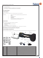
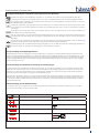
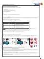
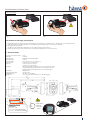
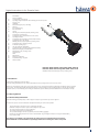
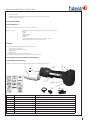
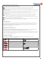
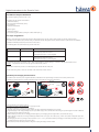
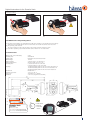
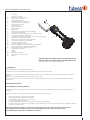
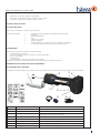
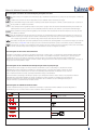
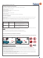
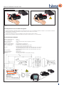
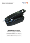
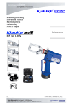
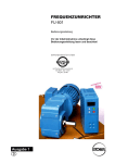
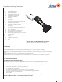
Originalbetriebsanleitung Powerlec Vario Inhalt 1.Einleitung 2.Sicherheitsbestimmungen 2.1 Allgemeine Sicherheitsbestimmungen 2.2 Weitere Sicherheitsregeln 3. Beschaffenheit des Werkzeugs 3.1 Bestimmungsgemäße Verwendung 3.2 Vorhersehbarer Fehlgebrauch bzw. unsachgemäße Handhabung 3.3 Restgefahren 4. Vor Inbetriebnahme 4.1 Kurzinspektion 4.2 Aufschriften 5. Handhabung des elektro-hydraulischen Stanzgerätes 5.1 Beschreibung der Komponenten 5.2 Kurzbeschreibung der wesentlichen Leistungsmerkmale des Werkzeugs 5.3 Beschreibung der Betätigungsfunktion 5.4 Beschreibung der automatischen Steuerung des Stanzvorgangs 5.5 Beschreibung der Leuchtdiodenanzeige 6. Arbeiten mit dem elektro-hydraulischen Stanzgerät 6.1 Beschreibung des Stanzvorgangs 6.2 Einzelne Arbeitsschritte 6.3 LED zur Ausleuchtung des Arbeitsbereiches 6.4 Anwendungsbereich (u.a. Materialdicken) 6.5 Hinweise zur Verwendung des Akkus und des Ladeteils 6.6 Verhalten bei Störung am Stanzgerät 7. Technische Daten 8.Sonstiges 8.1 Wartung 8.2 Aufbewahrung und Transport 8.3 Außerbetriebenahme / Entsorgung 8.4 Kontakt Powerlec Vario ohne Rundlocher 2629-7200-00-00 Powerlec Vario mit Rundlocher 2629-7200-01-00 Abbildung: Handgehaltenes akkubetriebenes Lochstanzgerät 1. Einleitung Vielen Dank, dass Sie sich für den Powerlec Vario entschieden haben. Diese Betriebsanleitung gibt Ihnen eine detaillierte Anleitung zur Handhabung und zum sicheren Umgang mit dem Werkzeug. Bitte bewahren Sie diese Betriebsanleitung sorgfältig auf und sorgen sie dafür, dass sie vom Bedienpersonal gelesen, verstanden und eingehalten wird. Diese Betriebsanleitung ist während der gesamten Lebensdauer des Gerätes mitzuführen. Sollten Sie nach dem Lesen der Betriebsanleitung noch Fragen zum Werkzeug oder der Funktion selbst haben, kontaktieren Sie bitte Ihren lokalen Vertrieb oder uns als Hersteller. 2 Sicherheitsbestimmungen 2.1 Allgemeine Sicherheitsbestimmungen Werkzeuge mit bewegten Teilen bergen immer das Risiko von Verletzungen und erfordern ein großes Maß an Achtung und Sorgfalt. Um Risiken zu vermeiden lesen Sie bitte diese Betriebsanleitung aufmerksam durch bevor sie dieses Werkzeug in Betrieb nehmen. • • • • • • • Das Werkzeug darf nur in einwandfreiem Zustand betrieben werden Veränderungen müssen sofort dem Vorgesetzten gemeldet werden Die Arbeitsumgebung ist aufzuräumen Der Arbeitsbereich ist gut auszuleuchten Das Bedienpersonal ist verpflichtet geeignete Schutzkleidung zu tragen (Schutzbrille) Das Arbeiten an dem Werkzeug ist zu unterlassen, wenn die Konzentration herabgesetzt sein könnte (z.B. durch Medikamente- oder Alkoholeinnahme) Kinder fernhalten Das Werkzeug ist nicht für andere, als in dieser Betriebsanleitung beschriebene Arbeiten geeignet und bestimmt. Im Falle von Missbrauch haften wir nicht für daraus resultierende Schäden. 1 Betriebsanleitung Powerlec Vario 2.2 Weitere Sicherheitsregeln beim Umgang mit dem Powerlec Vario • • • • • • Die Inbetriebnahme und das Einrichten des Werkzeugs darf nur durch fachkundiges Personal erfolgen, welches auch diese Betriebsanleitung gelesen und verstanden hat Sorgfältiger Umgang mit dem Gerät Stärkere Schläge beschädigen das Gerät Beim Betrieb von Elektromotoren kann es zur Funkenbildung kommen, durch die feuergefährliche oder explosive Stoffe in Brand gesetzt werden können Bei dem Powerlec Vario handelt es sich um ein handgeführtes Gerät das nicht eingespannt werden darf. Es darf nicht für den stationären Einsatz verwendet werden Das elektro-hydraulische Stanzgerät darf nicht bei starkem Regen oder unter Wasser eingesetzt werden Für auftretende Schäden, ausgelöst durch unsachgemäße Handhabung oder Nichtbefolgung der Sicherheitsvorschriften kann die häwa nicht haftbar gemacht werden. 3 Beschaffenheit des Werkzeugs Das handgehaltene akkubetriebene Lochstanzgerät entspricht dem Stand der Technik, sowie den geltenden Sicherheitsbestimmungen zum Zeitpunkt des Inverkehrbringens im Rahmen seiner bestimmungsgemäßen Verwendung. Das handgehaltene akkubetriebene Lochstanzgerät hydraulisch betätigt besitzt eine EG-Konformitätserklärung (siehe Anlage) und entspricht somit den Vorgaben der Maschinenrichtlinie 2006/42/EG. Technische Änderungen im Rahmen der Weiterentwicklung der Maschine bleiben vorbehalten. 3.1 Bestimmungsgemäße Verwendung Der Powerlec Vario ist ein handgehaltenes akkubetriebenes Lochstanzgerät zum Stanzen von Rund- und Formlöchern in Stahl-, Edelstahl- und Aluminiumbleche. Unter günstigen Voraussetzungen können auch manche Kunststoffe und Fieberglas bearbeitet werden (weiche Kunststoffmischungen in Verbindung mit scharfen Werkzeugen). Dazu sind vorab auf jeden Fall Versuche zu machen. Der Powerlec Vario kann mit folgenden häwa Stanzeinsätzen betrieben werden: • • • Standard Locher 2623, bestehend aus Stempel, Matrize und dazugehöriger Betätigungsschraube Rundlocher Plus 2682, bestehend aus Stempel, Matrize und dazugehöriger Betätigungsschraube Quadrat-, Rechteck-, Form- und Sonderlocher bestehend aus Stempel, Matrize und Zugbolzen / Betätigungsschraube Mit den Standardrundlochern 2623 und Sonderlochern können Löcher in Kunststoff, Fiberglas, Aluminium und Stahl gemacht werden. Mit den Rundlocher Plus 2682 können all die vorgenannten Materialien gelocht werden und zusätzlich noch Edelstähle. Weitere Voraussetzung: Durch das Funktionsprinzip „Betätigung durch eine Zugschraube“ muss zum Stanzen unbedingt vorgebohrt werden. 3.2 Vorhersehbarer Fehlgebrauch bzw. unsachgemäße Handhabung Bei jeder Änderung an dem Werkzeug und bei vorhersehbarem Fehlgebrauch bzw. unsachgemäßer Handhabung erlischt die EG-Konformitätserklärung des Herstellers und damit automatisch die Betriebserlaubnis. Vorhersehbarer Fehlgebrauch bzw. unsachgemäßer Handhabung sind: • Betrieb bei starkem Regen oder Schnee • Ausziehen, einpressen von Lagern oder ähnlichem • Betrieb mit stumpfen Werkzeugen • Nicht bestimmungsgemäße Verwendung 3.3 Restgefahren Konstruktiv konnten nicht alle Gefahren, ohne die bestimmungsgemäße Funktionalität einzuschränken, vermieden werden. Analysiert und bewertet wurden die Restgefahren des handgehaltenen akkubetriebenen Lochstanzgerätes mittels einer Risikobewertung. Konstruktiv nicht vermeidbare Restgefahren können sein: • Abscheren oder Quetschen von Gliedmaßen durch Nichtbeachten der Betriebsanleitung • Ungewollter Anlauf / Betätigung der Maschine • Schnittverletzungen durch Werkzeuge oder scharfe Bleche 2 Betriebsanleitung Powerlec Vario Bestehende Restgefahren können vermieden werden durch: • • • Aufmerksames Arbeiten Durch Beachten der Hinweise an der Maschine und in dieser Anleitung Durch Umsetzen der allg. Sicherheitsbestimmungen / Sicherheitsregeln 4. Vor Inbetriebnahme 4.1 Kurzinspektion Bitte prüfen Sie als erstes, ob Sie alle im Lieferumfang angeführten Teile erhalten haben. Lieferumfang: 1 Akku-betriebenes elektro-hydraulisches Stanzgerät Typ Powerlec Vario 1Akku 1Ladegerät 2Betätigungsschrauben 1Reduzieradapter 2Distanzhülsen 2 Bedienungsanleitungen (1x vom Gerät, 1x vom Ladegerät) 1 Lochersatz (bei Powerlec Vario mit Rundlocher) 4.2 Aufschriften Auf dem Gerät befinden sich folgende Aufschriften und Hinweise: • Firmenname mit Anschrift • Kurzdarstellung der stanzbaren Lochdurchmesser • die Stanzkraft • die Seriennummer • und ein Hinweis auf eine Gefahr beim Stanzvorgang Die Positionen der Aufschriften sind in der Abbildung unter Punkt 7. „Technische Daten“ zu entnehmen 5. Handhabung des elektro-hydraulischen Stanzgerätes 5.1 Beschreibung der Komponenten Das elektro-hydraulische Stanzgerät mit der Typbezeichnung Powerlec Vario ist ein handgeführtes Gerät und besteht aus folgenden Komponenten: 2 1 3 4 3 7 6 8 5 BL1830 Abb. 1 Pos.-Nr. Bezeichnung Funktion 1 Stanzkopf Kopf zur Aufnahme des Zugbolzens einschließlich Stempel und Matrize 2 Rückstellschieber Schieber zum Abbrechen des Stanzvorganges im Fehler-, bzw. Notfall 3 LED (rot) Anzeige Akku-Kapazität, Wartungsanzeige und Fehler 4 Akkuentriegelung Entriegelungsschieber für den Akku 5 Akku (BL 1830) wiederaufladbarer Li-Ion Akku 6 LED (weiß) zur Ausleuchtung des Arbeitsumfeldes 7 Bedienungsschalter Auslösung des Stanzvorgangs 8 Netzadapter zum Anschluss an das 230V Wechselstromnetz 3 Betriebsanleitung Powerlec Vario 5.2 Kurzbeschreibung der wesentlichen Leistungsmerkmale des Werkzeugs Das Stanzwerkzeug ist mit einem Nachlaufstopp ausgerüstet, der den Vorschub nach Loslassen des Bedienungsschalters sofort stoppt. Der Stanzkopf kann stufenlos um die Längsachse rotiert werden. Dieses ermöglicht Montagen auch an sehr schlecht zugänglichen Stellen. Eine eingebaute weiße LED beleuchtet den Arbeitsbereich nach Aktivierung des Bedienungsschalters und schaltet sich nach 15 s wieder aus. Dieses Merkmal läßt sich auch ausschalten. Das kompakte ergonomische geformte Gehäuse besteht aus 2 Komponenten. Der Griffbereich ist durch seine Gummierung besonders rutschfest und zusammen mit dem schwerpunktoptimierten Gehäuse liegt das Werkzeug besonders gut in der Hand und unterstützt so ermüdungsfreies Arbeiten. Alle Funktionen unserer Geräte können über einen Bedienknopf gesteuert werden. Dadurch bekommen wir eine einfache Handhabung und besseren Halt als bei einer Zweiknopfbedienung. Durch die Li-Ionen Batterien, die weder Memory Effekt noch Selbstentladung kennen, hat der Bediener auch nach langen Arbeitspausen immer ein einsatzbereites Gerät. Dazu kommt noch ein geringeres Leistungsgewicht mit 50% mehr Kapazität und kurzen Ladezeiten im Vergleich zu NiMH Akkus. Das eingesetzte Öl ist ein biologisch schnell abbaubares und nicht wassergefährdendes Hochleistungshydrauliköl und mit dem Blauen Engel ausgezeichnet. Das Öl ist für sehr niedrige Temperaturen geeignet und hat exzellente Schmiereigenschaften. Das Stanzwerkzeug ist mit einer Mikroprozessor-Steuerung ausgestattet, die z.B. den Motor nach vollendetem Stanzvorgang abschaltet, Service-Intervalle anzeigt, den Ladezustand des Akkus angibt und eine Fehlerdiagnose durchführt. 5.3 Beschreibung der Betätigungsfunktionen Ein Stanzvorgang wird durch die Betätigung des Bedienungsschalters (Pos. 7) ausgelöst. Das elektro-hydraulische Stanzgerät Typ Powerlec Vario ist mit einer speziellen Schaltung ausgestattet, die den Motor nach erfolgter Stanzung selbständig abschaltet. Der Bedienungsschalter (Pos. 7) muß während des Stanzvorganges kontinuierlich gedrückt werden. Das Gerät ist mit einem Nachlaufstopp ausgerüstet, der den Vorschub nach Loslassen des Bedienungsschalters sofort stoppt. Durch einmaliges Betätigen des Rückstellschiebers (Pos. 2) kann der Druckring wieder in seine Ausgangsposition zurückgefahren werden. 5.4 Beschreibung der automatischen Steuerung des Stanzvorganges Der Powerlec Vario ist mit einer Mikroprozessor-Steuerung ausgestattet, die den Ablauf einer Stanzung steuert. Die Lochstanze schaltet sich automatisch ab, wenn nicht innerhalb von etwa 1,5 Sekunden nach dem Einschalten ein Stanzvorgang beginnt. Das ist der Fall, wenn der Stempel nicht nah genug an das Blech herangeschraubt wurde. Durch das automatische Abschalten wird der Bediener auf diesen Fehler aufmerksam gemacht. Außerdem wird durch die Vermeidung des unnötigen Leerlaufs Akkuladung gespart. Nach vollendetem Stanzvorgang, also wenn der Stempel das Blech durchtrennt hat, schaltet sich der Motor der Lochstanze automatisch ab. Diese Funktion dient der Sicherheit des Bedieners und schont die Stanzwerkzeuge. Ohne diese Sicherheitsfunktion kann es leicht passieren, daß der Stempel den Grund der Matrize mit voller Kraft berührt. Dadurch werden die Schneiden des Stempels beschädigt. Im schlimmsten Fall kann die Matrize dabei auseinanderbrechen. 5.5 Beschreibung der Leuchtdiodenanzeige Die Leuchtdiode (Pos. 3) dient in Verbindung mit der Steuerungselektronik zur Information über den Zustand des Akkus (Pos. 5) und des Werkzeuges. Im Einzelnen leuchtet die Diode in folgenden Fällen: Wann 20 sec Warum nach Arbeitsvorgang nach Einsetzen des Akkus Batterie ist schwach Selbsttest 2x nach Arbeitsvorgang muss durchgeführt werden 20 sec/2Hz während der Übertemperatur Werkzeug zu heiß 20 sec/5Hz nach Arbeitsvorgang 20 sec 20 sec/2Hz 4 muss durchgeführt werden Betriebsanleitung Powerlec Vario 6. Arbeiten mit dem elektro-hydraulischen Stanzgerät 6.1 Beschreibung des Stanzvorganges Der Stanzvorgang wird gekennzeichnet durch das Einziehen des Stempels in die Matrize. Dabei befindet sich das zu bearbeitende Blech zwischen Stempel und Matrize. Um einen Stanzvorgang einleiten zu können ist es erforderlich, daß der Stempel so an das zu lochende Blech herangeschraubt wird, daß ein Kontakt zwischen Stempel und Blech gegeben ist. Diese Forderung leitet sich von einer integrierten Mikroprozessor-Steuerung ab, die u.a. auf diese Weise sicherstellt, daß für den Stanzvorgang der gesamte Hub zur Verfügung steht. Hat der Anwender den Stempel nicht bis an das Blech herangeschraubt, schaltet sich das Gerät kurz nach der Auslösung automatisch ab. Nach Auslösung des Bedienungsschalters wird relativ zum lochenden Blech der Stempel bestimmungsgemäß in das Blech eingezogen, wobei sich der Grundkörper um den entsprechenden Hub vom Blech wegbewegt. Diese Bewegung kann durch das Ausfahren des Druckrings optisch verfolgt werden. Ein Stanzvorgang ist abgeschlossen, wenn die Stanzeinsätze ineinander gefahren sind. Zu diesem Zeitpunkt muß der Bedienungsschalter losgelassen werden, um eine Beschädigung des Stempels, bzw. der Matrize, auszuschließen. Anschließend läßt sich der Stempel aus dem Blech herausziehen. Diese Abschaltung wird bei Blechstärken > 1,0 mm automatisch durch die Mikroprozessorsteuerung vorgenommen. Bei dünnen Blechen und bei weichen Werkstoffen (z.B. Kunststoffe) ist die automatische Abschaltung nicht immer gewährleistet und der Bediener muß das Gerät manuell abschalten. Sollte während des Stanzvorganges das Überdruckventil auslösen, so wurde die maximal zulässige Kraft überschritten und der Stanzvorgang ist sofort abzubrechen. Durch einmaliges Betätigen des des Rückstellschiebers (Pos. 2) fährt der Druckring selbständig in die Ausgangsposition zurück. Nachdem die Blechreste aus der Matrize entfernt worden sind, kann ein weiterer Stanzvorgang vorgenommen werden. 6.2 Einzelne Arbeitsschritte Als erstes wird der zueinander passende Stanzeinsatz (Stempel und Matrize) bereitgelegt. Achtung: Es dürfen nur original häwa Komponenten verwendet werden, da es bei Fremdkomponenten zu Materialversagen kommen kann wodurch umstehende Personen verletzt werden können. Bestimmen Sie den genauen Ort für das Loch. Bohren Sie ein Loch etwa 1-1,5 mm größer als der Zugbolzen. Achtung: Beim Bohren und beim Stanzen Schutzbrille tragen. Achtung: Nicht mit unvollständig aufgeschraubtem Gewinde lochen. Wenn das Gewinde beispielsweise des Stempels nicht vollständig auf den Zugbolzen aufgeschraubt werden kann, so muß der Aufbau wieder demontiert und die Distanzbuchse entfernt werden. Stellen Sie darüberhinaus sicher, daß die Schneidseite des Stempels dem Blech zugewand ist. Achtung: Der Stempel muß so aufgeschraubt werden, daß er schon leichten Kontakt mit dem Blech hat. Achtung: Bei der Montage der Zugbolzen für Quadratlocher darf ausschließlich die dem Innendurchmesser des Druckrings angepaßte Seite des Zugbolzens eingeschraubt werden. Bei Nichtbeachtung wird der Druckring auf den Bolzen aufgeschoben, dadurch verklemmt er sich und kann nicht mehr zurückgefahren werden. Durch diese Fehlbedienung wird der Druckring beschädigt und muß ausgetauscht werden. Nun wird, wie in Kap. 6.1 beschrieben, der Stanzvorgang durchgeführt. Zum besseren Verständnis der Abläufe und Funktionen des Gerätes wird dringend empfohlen, die Kap. 5.4 und 5.5 aufmerksam zu lesen. Achtung: Achtung: Achtung: Stellen Sie sicher, daß sich während des Stanzens keine Personen vor oder in der unmittelbaren Nähe des Stempels aufhalten, da diese Personen im Falle eines Materialversagens durch herumfliegende Splitter verletzt werden können. Während des Stanzvorganges nicht mit den Händen in den Stanzbereich eingreifen, da dies zu Quetschungen und Abscherungen führen kann. Das Gerät schaltet nach dem beendeten Stanzvorgang selbständig ab. Dazu muss der Bedienungsschalter kontinuierlich gedrückt gehalten werden, bis der Stanzvorgang automatisch beendet wird. Bei Blechstärken ≤ 1 mm oder weichen Werkstoffen (z.B. Kunststoffe) muß der Bediener das Gerät durch Loslassen des Bedienungsschalters nach dem Durchstanzen abschalten. Achtung: Das Gerät darf nach dem Durchlochen/Abschalten nicht erneut betätigt werden, da es ansonsten zu einem Kontakt zwischen Stempel und Matrize kommen kann. Es kann dabei zu einem Bruch der Locher kommen und Personen können durch herumfliegende Splitter verletzt werden. Der Stempel und die Matrize müssen demontiert und die Blechreste entfernt werden. Achtung: Der Stanzvorgang kann jederzeit durch Loslassen des Bedienungsschalters unterbrochen werden. Achtung: Vor Auswechslung der Stanzeinsätze unbedingt Akku gegen unbeabsichtigtes Betätigen aus dem Gerät entfernen. 5 Betriebsanleitung Powerlec Vario 6.3 LED zur Ausleuchtung des Arbeitsbereiches Standardmäßig ist die Beleuchtung beim Betätigen für 15 sec eingeschaltet. Die Beleuchtung kann wie folgt abgeschaltet werden: 1. Akku entnehmen 2. Bedienungsschalter (Pos.7) drücken und halten 3. Akku wieder einsetzen 4. Bedienungsschalter loslassen Wieder einschalten: 1. Akku entnehmen 2. Akku wieder einsetzen (ohne Bedienungsschalter (Pos.7) zu drücken) 6.4 Anwendungsbereich Mit dem elektro-hydraulischen Stanzgerät vom Typ Powerlec Vario kann eine große Anzahl verschiedener Stanzeinsätze zum Lochen unterschiedlicher Lochgeometrien betätigt werden. Neben Stahl-, Edelstahl (V2A und V4A) und Aluminiumblechen können unter günstigen Vorraussetzungen auch Fieberglas und manche Kunststoffe bearbeitet werden. Dazu sind vorab auf jeden Fall Versuche zu machen. Die folgende Tabelle gibt die Obergrenzen der zu stanzenden Lochgrößen wieder: Material Blechstärke Typ St 37 2,5 mm Rundlocher bis ø 80 mm Quadratlocher bis 68 mm x 68 mm Rechtecklocher bis 115 mm Diagonale Edelstahl (V2A) 2,0 mm Rundlocher bis ø 80 mm Quadratlocher bis 68 mm x 68 mm Rechtecklocher bis 115 mm Diagonale Bei nicht von dieser Tabelle erfassten Kombinationen bei denen Sie Zweifel an der Stanzbarkeit haben, empfehlen wir eine Rücksprache mit uns. Achtung: Es dürfen nur die zum bestimmungsgemäßen Gebrauch vorgesehenen Materialien gelocht werden. Sollten andere Materialien gestanzt werden müssen, ist eine Rücksprache mit dem Werk zwingend erforderlich. Vor Arbeitsbeginn ist ein spannungsfreier Zustand der zu lochenden Bleche sicherzustellen. 6.5 Hinweis zur Verwendung des Akkus und des Ladeteils Neben dieser Orginalbetriebsanleitung liegt dem Lieferumfang dieses Gerätes noch eine Bedienungsanleitung für das Schnellladegrät bei. Diese enthält wichtige Sicherheits- und Gebrauchsanweisungen die vor der Benutzung unbedingt gelesen werden müssen. K CLIC Abb. 2 (BL1815) 10 - 40°C (BL1830) 15 min. 22 min. Abb. 3 Li-ion Kurzbeschreibung des Ladevorganges Das Ladegerät ist für Wechselspannung von 230V mit einer Frequenz von 50 Hz ausgerüstet. Neue Akkus sollten vor dem ersten Gebrauch nachgeladen werden. 1. Stecken Sie den Netzstecker des Ladegerätes in die Steckdose. Die Ladekontrolllampe blinkt wiederholt Grün. 2. Richten Sie den Akku auf die Führung des Ladegerätes aus und führen Sie ihn bis zum Anschlag ein. Die Kontaktabdeckung des Ladegerätes wird durch Einschieben des Akkus geöffnet und durch Herausziehen des Akkus geschlossen. 3. Wenn der Akku eingesetzt wird, leuchtet die rote Ladekontrolllampe auf, und der Ladevorgang beginnt mit einer kurzen voreingestellten Melodie bis der Abschluss des Ladevorgangs mit einem Ton bestätigt wird. 4. Wenn der Ladevorgang beendet ist, wechselt die Ladekontrollampe von Rot auf Grün, und eine Melodie oder ein Summton (langer Piepton) wird abgegeben, um den Abschluss des Ladevogangs zu melden. 5. Die Ladezeit ist je nach der Temperatur (10°C - 40°C), bei welcher der Akku geladen wird, und dem Zustand des Akkus (z.B. neuer oder längere Zeit unbenutzter Akku) unterschiedlich. 6. Nach dem Laden nehmen Sie den Akku aus dem Ladegerät heraus, und trennen Sie das Ladegerät vom Stromnetz. 6 Betriebsanleitung Powerlec Vario Einsetzen des Akkus: 1. 2. CLICK Abb. 4 Abb. 5 6.6 Verhalten bei Störungen am Stanzgerät a) Regelmäßiges Blinken/Leuchten der roten Leuchtdiode (Pos. 3). Erläuterung in der Tabelle unter 5.5 „Beschreibung der Leuchtdiodenanzeige“ Sollte sich die Störung nicht abstellen lassen, ist das Werkzeug an das nächst gelegene Service Center zu schicken. b) Das Stanzwerkzeug verliert Öl. Das Werkzeug ist einzuschicken. Nicht öffnen und die Geräteversiegelung nicht entfernen. c) Bei allen anderen Fragen wenden sie sich bitte an die häwa Service-Rufnummer: Tel: +49 7353 9846 0 7. Technische Daten Gewicht des Gerätes mit Akku: Stanzkraft: Antriebsmotor: Motorspannung: Akku-Kapazität: Akku-Ladezeit: Stanzzeit: Kapazität: Hydrauliköl: Umgebungstemperatur: Schalldruckpegel: Vibrationen: 1 2,2 kg ca. 60 kN Gleichstrom-Permanentfeldmotor 18 V DC 3 Ah (BL1830) oder 1,3 Ah (BL1815) 22 min BL1830 / 15 min BL1815 5 s bei ø 22,5 mm, 3 mm St37 6 s bei ø 61,5 mm, 3 mm St37 120 Stanzungen/Akku bei Ø 22,5 mm und 3,4 mm Bleche St 37 bzw. 190 Stanzungen/Akku bei Ø 22,5 mm und 3 mm Bleche St 37 bzw. 280 Stanzungen/Akku bei Ø 22,5 mm und 2,5 mm Bleche St 37 Rivolta S.B.H. 11 -20°C bis +40°C 70,6 dB (A) in 1m Abstand < 2,5 m/s² (gewichteter Effektivwert der Beschleunigung) häwa GmbH & Co. KG • Industriestraße 12 • D-88489 Wain 4 75 45 .1 HE NOCH NICHT FREIGEGEBEN Stanzkraft (Force): 60 kN HE.14577_D Punch driver 6 Powerlec Vario 457 häwa GmbH & Co. KG • Industriestraße 12 • D-88489 Wain 3 5 HE.1 2 HE.9625 304711 ð serial number CV ðdatecode 142 ðconsecutive number Max. Lochergröße: Ø 80mm, 2,5mm ST37/2mm VA (Max. Punch Size): 68 x 68mm, 2,5mm ST37/2mm VA 5 HE.14577 Rev. D Größe: 43 x 18 mm 7 Betriebsanleitung Powerlec Vario 8. Sonstiges 8.1 Wartung Optische Überprüfung vor jeder Nutzung. Das Stanzgerät ist nach jedem Gebrauch zu reinigen und trocken zu lagern. Sowohl Akku als auch Ladegerät müssen vor Feuchtigkeit und vor Fremdkörpern geschützt werden. Das Gerät ist prinzipiell wartungsfrei. Lediglich sind die Bolzenverbindungen am Stanzkopf und die beweglichen Komponenten des Stanzkopfes leicht einzuölen. Um eine einwandfreie Funktion des Werkzeugs sicherzustellen und möglichen Funktionsstörungen vorzubeugen, sollte das Stanzwerkzeug nach Ablauf eines jeden Jahres oder nach 10.000 Stanzungen zur Wartung oder zum Service eingeschickt werden. Im Rahmen des bestimmungsgemäßen Gebrauchs dürfen vom Kunden nur die Stanzeinsätze und die Akkus gewechselt werden. Achtung: Geräteversiegelung nicht beschädigen! Bei Beschädigung der Geräteversiegelung erlischt der Garantieanspruch. 8.2 Aufbewahrung und Transport Um das Stanzgerät vor Beschädigungen zu schützen, muß das Stanzgerät nach Gebrauch und nachdem es gesäubert worden ist, in den Transportkoffer gelegt werden, der dann anschließend sicher zu verschließen ist. 8.3 Außerbetriebnahme / Entsorgung Auch bei qualitativ hochwertigen Geräten ist irgendwann der Zeitpunkt gekommen, an dem die Entsorgungsfrage gestellt werden muß. Die Entsorgung der einzelnen Komponenten des Stanzgerätes muß getrennt erfolgen. Dabei muß zuerst das Öl abgelassen werden und an speziellen Abnahmestellen entsorgt werden. Achtung: Unkontrolliertes Ablassen oder unsachgemäße Entsorgung von Hydraulikölen steht unter Strafe. (Umwelthaftungsgesetz) Achtung: Akkus enthalten für die Umwelt gefährliche Stoffe. Aus diesem Grund ist jeder Verbraucher nach dem BattG verpflichtet, ge- und verbrauchte Batterien einer Sammelstelle zur Entsorgung zuzuführen. Eine Entsorgung über den Hausmüll ist verboten! Falls der Akku bei einer öffentlichen Sammelstelle nicht abgegeben werden kann, kann er „Frei Haus“ an den Hersteller oder an die häwa zur kostenlosen Entsorgung gesendet werden. Bei der Entsorgung der restlichen Teile des Stanzgerätes beachten Sie bitte die EG-Umweltstandards. Wir empfehlen wegen möglicher Umweltverschmutzung die Entsorgung durch zugelassene Fachunternehmen vornehmen zu lassen. Eine kostenfreie Rücknahme des Altgerätes durch den Hersteller kann nicht zugesagt werden. 8.4 Kontakt Sie erreichen häwa unter: Tel: +49 7353 9846 0 Fax: +49 7353 1050 e-mail: [email protected] 8 Original instructions for the Powerlec Vario Contents 1.Introduction 2. Safety regulations 2.1 General safety requirements 2.2 Operating safety instructions when handling the Accu Flexi-power 3. Intended use 3.1 Utilization 3.2 Misuse through improper handling 3.3 Hazards 4.Pre-commissioning 4.1 Brief inspection 4.2 Labels 5. Handling of the Electro-hydraulic punching device 5.1 Description of components 5.2 Description of the essential features of the device 5.3 Operating functions 5.4 Description of the automatic control (microprocessor) 5.5 Description of the LED display 6. Working with the electro-hydraulic punching device 6.1 Description of the punching process 6.2 Individual operating steps 6.3 LED for workspace illumination 6.4 Application scope (including material thickness table) 6.5 Battery and charging unit instructions 6.6 Malfunction of the punching device 7. Technical data 8.Other 8.1 Maintenance 8.2 Storage and transport 8.3 Decommissioning / disposal 8.4 Contact details Powerlec Vario without round punch 2629-7200-00 Powerlec Vario with round punch 2629-7200-01-00 Illustration: Hand-held battery-operated punching device 1. Introduction Thank you for choosing the Powerlec Vario. These operating instructions are the detailed instructions for the operating and the safe use of the device. Please keep this manual in a safe place, and ensure that it is read, understood and that the instructions are followed by the operators of the device. The instructions should always accompany the device through its entire operating lifetime. If you have any questions about the device, or its functioning after reading the instructions, please contact your local distributor or the manufacturer directly. 2. Safety regulations 2.1 General safety instructions Tools with moving parts always carry a risk of injury and require a great deal of respect and diligence. To avoid risks, please read the instructions carefully before taking the device into operation. • • • • • • • The tool may only be operated in proper functioning condition. Variations of any kind must be reported immediately to a supervisor. The device should be utilized in a tidy workspace. The working area should be well illuminated. The operator is obligated to wear appropriate protective clothing (goggles). Refrain from operating the tool under reduced concentration. (E.g. through the influence of drugs or alcohol intake.) Keep children away. The device is not suitable to be operated by any other person/s as described in the instructions. häwa GmbH will not be held liable for any damages whatsoever resulting from abuse of any kind. 9 Original instructions for the Powerlec Vario 2.2 Operating safety instructions when handling the Powerlec Vario • • • • • • Commissioning and equipping of the tool may only be carried out by trained personnel, whom have read and understood the operating instructions. Careful handling of the device. Hard blows to the device will lead to damage. Operation of electrical motors can lead to sparking, which in turn can set fire to flammable and explosive materials. The Powerlec Vario is a hand-held device that may not be clamped and may not be utilized for stationary applications. The electro hydraulic punching device may never be used in heavy rain or under water. häwa GmbH will not be held liable for any damages caused by improper handling or failure to follow safety instructions. 3 Intended use The hand-held battery-powered punch is state of the art technology within the context of its intended use and coherent safety requirements, at time the device was put into circulation. The hand-held battery-powered punch is hydraulically operated and has an EC declaration of conformity (see annex), and thus meets the requirements as set out in the machinery directive 2006/42/EG. (DGUV Test - German Test und Certification System for Statutory Accident Insurance). häwa GmbH & Co. KG reserves all rights. 3.1 Utilization The Powerlec Vario is a hand-held battery-operated punching device for punching holes in circular and shaped forms in steel, stainless steel and aluminium sheets. Under favorable conditions, some synthetics and fiberglass can also be processed (soft plastic compounds in conjuction with sharp tools). It is advisable to make a prelimanary punch before commencing. The Powerlec Vario can be used with the following häwa punching sets: • • • Standard punch 2623; consisting of stamp, die and corresponding actuation screw. Round punch Plus 2682; consisting of stamp, die and corresponding actuation screw. Square, rectangle, shaped and special punch; consisting of punch, die and tension bolt or actuation screw. With the standard round punch 2623 and special punch, holes in plastic, fiberglass, aluminum and steel can be made. With the round punch Plus 2682, punches can be punched in all the aforementioned materials and in addition, in stainless steel. Additional requirements: Through the operating principle “actuation through a tension bolt“, pre-drilling is required prior to punching. 3.2 Misuse through improper handling The EG-Conformity and Incorporation Regulations Certification awarded to häwa GmbH & Co. KG is rendered null and void, through any unauthorized changes, inappropriate utilization or mal-handling, restricting the consent to operate. Improper handling includes: • Operating in heavy rain or snow. • Pulling-, pressing or similar action, of bearings. • Operating with blunt tools. • Utilization outside the intended use of the device. 3.3 Hazards Constructively, not all hazards, without limiting the intended functionality, can be avoided. The residual risk of the hand-held battery-powered punching device, must be analyzed and assessed before operating commences. Possible unavoidable construction risks: • Scrapes or crushed limbs caused by not following the instructions carefully. • Accidentaly switching the device to operation. • Cuts caused by sharp tools or sheet metal. 10 Original instructions for the Powerlec Vario Existing residual risks can be avoided through: • • • Attentive operation. Following the recommendations and instructions as set out in this instruction manual. Applying the safety regulations. 4. Pre-commissioning 4.1 Brief inspection Please check if all the components listed was included in delivery. Scope of delivery: 1 Battery-operated electro-hydraulic punching device type; Powerlec Vario 1 Battery 1 Charger 2 Actuation screws 1 Bush adapter 2 Bushes 2 Operating instructions (1 for the device and 1 for the charger) 1 Punch set (for Powerlec Vario with round punch) 4.2 Labels The following labels and instructions can be found on the device: • company name and address, • summary of punchable hole diameter, • punching force, • serial number, • and hazard reference for the punching process. Label position descriptions can be found under heading 7. Technical data. 5. Handling of the electro-hydraulic punching device 5.1 Description of components The Powerlec Vario is a hand-held punching device consisting of the following components: 3 4 2 1 7 6 8 5 BL1830 Ill. 1 Item Nr. Designation Function 1 Punching head Head for hosting a tension bolt including punch and die. 2 Reset slide Slider to abort the punching process in case of malfunction. 3 LED (red) Displays battery capacity, maintenance and error. 4 Battery release latch Release latch for the battery. 5 Battery (BL 1830) Rechargeable Li-Ion battery. 6 LED (white) To illuminate the working environment. 7 Operation switch Triggers the punching process. 8 AC adapter For connection to the 230V AC mains. 11 Original instructions for the Powerlec Vario 5.2 Description of the essential features of the device The punching device is equipped with a overrun stop, which stops the feed immediately after letting go of the control switch. The cutting head can be rotated continuously around the longitudinal axis. This allows installations in inaccessible spaces. A built-in white LED illuminates the workspace after activation of the control switch and turns off automatically after 15 seconds.. This feature can also be switched off. The compact, ergonomic shaped housing consists of 2 components: the grip area is particularly slip-free through its rubber coating and together with the barycentric housing, the hand-held device is comfortable to hold and assists in fatigue-free application. All functions of the device can be controlled with one control knob. Resulting in simple handling and improved support, in comparison to two-button operation. Li-Ion batteries are known for not having memory or self-discharge effects, providing the operator even after long breaks, always with an operational device. In contrast to NiMH batteries, Li-Ion batteries weighs less, haves 50% more capacity and shorter recharge times The oil used, is a fast biodegradable and non-water-endangering high performance hydraulic oil with the Blue Angel seal of aprovement. The oil is suitable for very low temperatures, and has excellent lubricating properties. The punching device is equipped with a microprocessor control, that for example switches the motor off after completing a stamping operation, indicating maintenance intervals- and battery charge status, and performs an error-diagnostic. 5.3 Operating functions A punching operation is triggered by operating the control switch (item 7). The electro hydraulic punching device type Powerlec Vario is equipped with a special circuit, which switches the motor off automatically after a successfull punching process. The control switch (Item 7) must be pressed continuously during the punching process. The device is equipped with a overrun stop that automatically stops the feed process after the control switch is released. Through a single press of the reset slide (item 2), the pressure ring returns to its original position. 5.4 Description of the automatic control The Powerlec Vario is equipped with a microprocessor controller that controls the flow of a die-cut. The punch turns off automatically after about 1.5 seconds after a faulty punching process, when the stamp is not screwed close enough to the metal sheet. The automatic off switch avoids unnecessary battery power loss, whilst bringing the error under the attention of the operator. After a successfull punching process, i.e. when the stamp has cut the metal, the puncing motor turns off automatically. This serves as a safety function for the operator and protects the punching tools. This safety function prevents that the punch touches the die base with full force, consequently damaging the stamp, or in worst cases breaking the die apart. 5.5 Description of LED display The LED display (item 3) in conjunction with control electronics, provide information on the status of the battery (item 5) and of the device. In particular, the LED display lights up in the following cases: When 20 sec Cause After operation After inserting the battery Battery power low Self test 2x After operation must be carried out 20 sec/2Hz During excessive temperature Device too hot 20 sec/5Hz After operation 20 sec 20 sec/2Hz 12 must be carried out Original instructions for the Powerlec Vario 6. Working with the electro-hydraulic punching device 6.1 Description of punching process The punching process is marked by the retraction of the stamp into the die. The metal sheet to be processed is between the punch and the die. In order to be able to initiate a punching operation, it is necessary that the stamp are scewed as such that the processable sheet and the stamp touches each other. This requirement is derived from the integrated microprocessor control system, that among other things, ensures that the entire hub is available for the punching process. If the operator did not screw the stamp close enough to to the processable sheet, the device will automatically switch off shortly after release. After triggering the operation switch, the stamp punches the processable sheet metal by punching through the sheet while the body moves away from the metal sheet through the stroke of the action. This movement can by optically followed through the pressure ring. A stamping process is complete, when the stamp and die are driven into each other. At this point, the control switch must be released to prevent possible damages to the stamp or the die. Subsequently, the stamp can be pulled out from the sheet. Shutdown follows automatically by the microprocessor for metal sheet thicknessess > 1,0 mm. For thinner metal sheets and synthetic materials (e.g. plastics), the automatic shutdown is not always garanteed and the operator must turn the power off manually. The pressure relief valve is released during a punching process, when the maximum force has been exceeded, resulting in the immediate cancellation of the punching process. By a single operation of the reset slide (item 2), the pressure ring independently returns to its starting position. After the sheet residue have been removed from the die, a further punching operation can be performed. 6.2 Individual operating steps First, prepare the matching punch (stamp and die). Caution: Only use original häwa components, as pirate or unfamiliar components can lead to material failure which may cause injuries to persons in the direct vicinity. Determine the exact location of the hole. Drill a hole of about 1-1.5 mm larger than the tension bolt into the metal sheet. Caution: When drilling and punching always wear goggles for safety. Caution: Do not punch with an incomplete screwed thread. If for example, the thread of the stamp can not be fully screwed on to the tension bolts, the assembly must then be disassembled and the bushes removed. Ensure that the cutting side of the stamp is turned towards the metal sheet. Caution: The stamp must be screwed as such that there is slight contact with the metal sheet. Caution: When mounting the tension bolt for square punches, only the inside diameter of the pressure rings‘ adapted side, may be screwed to the tension bolt. Failure to observe the aforementioned, leads to the pressure ring sliding onto the bolt, thus becomes jammed and can not be retracted. This faulty operation damages the pressure ring and must subsequently be replaced. The punching operation follows as described under heading 6.1. To better understand the processes and functions of the device, it is strongly recommended to read headings 5.4 and 5.5 carefully. Caution: Caution: Caution: Ensure that during the punching process that no other persons are present in the immediate vicinity of the punch, as they may get injured in case of material failure by flying splinters. During the punching process, do not intervene in the punching area with hands, as this can cause severe bruising and contusion injuries. The device switches off automatically after the punching process has ended. To do this, the control switch must be pressed continuously until the cutting process automatically ends. With metal shee≤t thicknessess of 1 mm or with soft materials (e.g. plastics), the operator must release the control switch after the punching process. Caution: The device may not be operated again directly after a punch/switch off process, as contact between the stamp and die may follow. This can lead to fraction of the punched hole and people can get hurt by flying splitter. The stamp and the die must be dismantled and metal residue removed. Caution: The punching process can be interrupted at any time by releasing the control switch. Caution: Before a tool change it is imperative that the operator removes the battery from the device, as to safegaurd against unintentional operation. 13 Original instructions for the Powerlec Vario 6.3 LED for workspace illumination By default, the lighting is turned on for 15 sec. The lighting can be switched off as follows: 1. Remove the battery 2. Press and hold control switch (item 7) 3. Insert battery 4. Release control switch Switch on again: 1. Remove the battery 2. Insert battery again (without pressing the control switch (item 7)) 6.4 Scope of application With the electro-hydraulic punch tool type Powerlec Vario various shapes can be punched with a number of different punching inserts. In addition to steel, stainless steel (V2A and V4A) and aluminium sheets, fiberglass and some plastics can also be processed under favourable conditions. Prelimanary test attempts are advised in these cases. The following table reflects the limits of the punched hole sizes: Material Sheet metal thickness Type St 37 2,5 mm Round holes up to Ø 80 mm Square holes up to 68 mm x 68 mm Rectangular punch up to 115 mm diagonal Stainless steel (V2A) 2,0 mm Round holes up to Ø 80 mm Square holes up to 68 mm x 68 mm Rectangular punch up to 115 mm diagonal Combinations not reflected in this table, where doubts exsists about the punching ability, we recommend that you consult with us first. Caution: Only within the intended use may approved materials be punched. Should other materials be punched, it is mandatory that you consult with the factory first. Before commencing work, a stress-free condition of the metal sheet must be ensured. 6.5 Battery and charging unit instructions In addition to the Accu Flexi-power original instructions, instructions for the quick charger is included in the delivery of this device. It contains important safety and operating instructions which is imperative to read before commencing. K CLIC Ill. 2 (BL1815) 10 - 40°C (BL1830) 15 min. 22 min. Ill. 3 Li-ion Short description of the charging process The charger is equipped for AC 230V with a frequency of 50 Hz. New batteries should be recharged before initial use. 1. Plug the power cord of the charger into the mains. The charge control light will flash green repeatedly. 2. Align the battery on the charger through the slide quide till the stopper. The terminal cover of the charger opens through the insertion of batteries and closes when the battery is pulled out. 3. When a battery is inserted, the red charging indicator lights up, the charging process begins with a preset short tone (beep). 4. When charging is completed, the charge control light switches from red to green, and a tone (beep) is made to report the completion of the char ging process. 5. The charging time varies depending on the temperature (10 ° C - 40 ° C) at which the battery is charging, and the battery condition (e.g. new or if the battery has been unused for an extended time). 6. Once loaded, remove the battery from the charger and unplug the charger from the mains. 14 Original instructions for the Powerlec Vario Inserting the battery: 1. 2. CLICK Ill. 4 Ill. 5 6.6 Malfunction of the punching device a) Red LED (item 3) flashing; see explanation in the table under heading 5.5 „Description of the LED display“. Should the error indication not turn off, the device must be send to the next service center for service. (b) The punching device loses oil. The device must be send for repair. Do not open and do not remove the seal of the device. c) For all other questions, please contact the häwa service number: Tel: +49 7353 9846 0 7. Technical data Weight of the device with battery: Punching force: Driving motor: Motor voltage: Battery capacity: Battery charging time: Punching time: Capacity: Hydraulic oil: Ambient temperature: Noise level: Vibrations: 1 häwa GmbH & Co. KG • Industriestraße 12 • D-88489 Wain 2.2 kg about 60 kN Continuous direct current field motor 18 V DC 3 Ah (BL1830) or 1,3 AH (BL1815) 22 min BL1830 / BL1815 15 min 5 seconds at ø 22.5 mm, 3 mm St37 6 seconds with ø 61.5 mm, 3 mm St37 120 Punches/battery at Ø 22.5 mm and 3.4 mm sheets St 37 or 190 Punches/battery at Ø 22.5 mm and 3 mm sheets St 37 or 280 Punches/battery at Ø 22.5 mm and 2.5 mm metal St 37 Rivolta S.B.H. 11 -20 ° C to + 40 ° C 70.6 DB(a) at 1 m distance <2.5 m/s ² (weight rms acceleration) 4 75 45 .1 HE NOCH NICHT FREIGEGEBEN Stanzkraft (Force): 60 kN HE.14577_D Punch driver 6 Powerlec Vario 457 häwa GmbH & Co. KG • Industriestraße 12 • D-88489 Wain 3 5 HE.1 2 HE.9625 304711 ð serial number CV ðdatecode 142 ðconsecutive number Max. Lochergröße: Ø 80mm, 2,5mm ST37/2mm VA (Max. Punch Size): 68 x 68mm, 2,5mm ST37/2mm VA 5 HE.14577 Rev. D Größe: 43 x 18 mm 15 Original instructions for the Powerlec Vario 8. Other 8.1 Maintenance Visual inspection advisable before each use. Ensure that the punching device is cleaned after every use and stored in a dry place. The battery and charger should also be protected against moisture and foreign objects. The device is basically maintenance-free. Only the bolt connections at the punching head and the moving components of the punching head should be oiled. To ensure proper functioning of the device and to prevent possible malfunction, the punching device should at the end of each year or after 10,000 punches go for maintenance or service. In the context of its intended use, only the punching inserts and batteries may be changed by the customer. Caution: Do not damage any of the seals! Any damages to the seals of the device voids the warranty. 8.2 Storage and transport To protect the punching device against damage, it should be cleaned after each use and stored away in the carrying case, preferable locked away safely. 8.3 Decommissioning/disposal Even high quality devices have a certain lifespan, where at some point the device must be disposed of. The disposal of all individual components of the punching device must be done separately. The oil must first be drained and disposed of at special collection points. Caution: Unlawfull draining or improper disposal is subject to punishment. (Environmental liability Act) Caution: Batteries contains dangerous substances for the environment. Every consumer is therefore obliged to follow the battery disposal regulations of used batteries at a collection point for disposal. Disposal of batteries in household waste is prohibited! If the battery can not be disposed of at a public collection point, it can be send to the distributor or to häwa for free disposal. When disposing of the remaining parts of the device, please refer to the EC environmental standards. It is recommended leaving the disposal to professional companies. Cost free return of the device for disposal to the manufacturer can not be guaranteed. 8.4 Contact details You can reach häwa at: Tel: +49 7353 9846 0 Fax: +49 7353 1050 e-mail: [email protected] 16 Manuel d’utilisation Powerlec Vario Contenu 1.Introduction 2. Consignes de sécurité 2.1 Consignes de sécurité générales 2.2 Autres règles de sécurité 3. Caractéristiques de l’outil 3.1 Utilisation conforme à sa destination 3.2 Cas d’usage incorrect prévisible ou de manipulation non conforme 3.3 Risques résiduels 4. Avant la mise en service 4.1 Courte inspection 4.2 Marquages 5. Maniement de la poinçonneuse électro-hydraulique 5.1 Description des composants 5.2 Description succincte des caractéristiques principales de l’outil 5.3 Description de la fonction d’actionnement 5.4 Description de la commande automatique du processus de poinçonnage 5.5 Description de l’afficheur lumineux à DEL 6. Travailler avec la poinçonneuse électro-hydraulique 6.1 Description du processus de poinçonnage 6.2 Les différentes étapes de travail 6.3 LED pour l’éclairage de la zone de travail 6.4 Domaine d’application (entre autres : épaisseurs de matériaux) 6.5 Conseils d’utilisation de l’accumulateur et du chargeur 6.6 Comportement en cas de défaut de l’appareil 7. Caractéristiques techniques 8.Autres 8.1 Entretien 8.2 Entreposage et transport 8.3 Mise hors service / Mise au rebut 8.4 Contact Powerlec Vario sans emporte-pièce rond 2629-7200-00-00 Powerlec Vario avec emporte-pièce rond 2629-7200-01-00 Photo : Poinçonneuse tenue à la main à accumulateur 1. Introduction Nous vous remercions d’avoir choisi l’outil Powerlec Vario. Ce manuel vous donne les instructions nécessaires à l’utilisation et au maniement sûr de cet outil. Veuillez garder ce manuel à portée de main près de l’appareil et faites en sorte qu’il soit lu, compris, respecté et pris en compte par le personnel utilisateur. Cette notice d’emploi doit accompagner l’outil pendant toute sa durée de vie. Dans le cas où après la lecture de ce manuel, vous auriez des questions concernant l’outil ou sa fonction, veuillez contacter notre filiale locale ou notre usine. 2 Consignes de sécurité 2.1 Consignes de sécurité générales Des outils ou machines en mouvement représentent toujours un risque de blessures importantes, et exigent une grande attention de la part des utilisateurs. Pour éviter tout risque, merci de lire attentivement ce manuel avant la mise en service de l’outil. • • • • • • • L’outil ne doit être utilisé que dans un état impeccable. Toute modification doit être signalée au responsable. L’environnement de travail doit être propre et bien rangé. Le poste de travail doit être bien éclairé. Le personnel utilisateur doit être muni d’équipements de protection adéquats (lunettes). Il ne faut pas vous servir de l’outil en cas de problèmes de concentration (dus p.ex. à la prise de médicaments ou à la consommation d’alcool). Il faut tenir les enfants à l’écart. Cet outil est uniquement à utiliser conformément aux indications décrites dans ce manuel. En cas d’usage abusif ou d’une utilisation pour des applications autres que celles indiquées dans cette notice, nous déclinons toute responsabilité pour les dommages et défaillances en résultant. 17 Manuel d’utilisation Powerlec Vario 2.2 Autres règles de sécurité concernant le maniement de l’outil Powerlec Vario • • • • • • La mise en service et le réglage de l’outil ne doivent être effectués que par un personnel qualifié et spécialisé ayant bien lu et compris ce manuel d’utilisation. Le maniement de l’appareil doit se faire avec précaution. Des chocs plus ou moins violents endommagent l’appareil. Lors du fonctionnement de moteurs électriques, il peut se produire des étincelles capables de mettre le feu à des matières inflammables ou explosives. Powerlec Vario est un outil destiné à être tenu à la main. Il ne doit pas être serré sur un support quelconque, ni être utilisé pour une application stationnaire. La poinçonneuse électrohydraulique ne doit pas être utilisée sous l’eau ou en cas de fortes pluies. La société häwa GmbH décline toute responsabilité en cas de dommages occasionnés par un maniement inapproprié ou par un non respect des prescriptions de sécurité. 3 Caractéristiques de l’outil La poinçonneuse tenue à la main à accumulateur correspond au standard technologique actuel et répond aux réglementations de sécurité en vigueur telles qu’elles sont définies au moment de sa mise sur le marché dans le cadre de son utilisation conforme à sa destination. La poinçonneuse hydraulique tenue à la main à accu possède une déclaration de conformité CE (voir annexe) et répond de ce fait aux exigences stipulées dans la directive européenne relative aux machines 2006/42/CE. Sous réserve de modifications techniques dans l’intérêt d’un perfectionnement permanent de la machine. 3.1 Utilisation conforme à sa destination Powerlec Vario est une poinçonneuse tenue à la main à accumulateur destinée à perforer des trous ronds ou des trous formés dans des tôles d’acier, d’acier inoxydable et d’aluminium. Dans des conditions favorables, il est possible également de poinçonner certains plastiques ou certaines fibres de verre (mélanges de plastiques souples en liaison avec des outils bien affûtés). Avant de commencer l’usinage, il est indispensable de procéder à des essais. Powerlec Vario peut fonctionner avec les inserts de poinçonnage häwa suivants : • • • Emporte-pièce standard 2623, comprenant poinçon, matrice et axe y afférent. Emporte-pièce rond Plus 2682, comprenant poinçon, matrice et axe y afférent. Emporte-pièce carré, rectangulaire et de formes spéciales, comprenant poinçon, matrice et axe. Les emporte-pièces standard 2623 et de formes spéciales permettent de percer des trous dans les plastiques, fibres de verre, l’aluminium et l’acier. Avec l’emporte-pièce rond Plus 2682, il est possible de percer tous les matériaux cités précédemment et en plus les aciers inoxydables. Autre condition : De par le principe de fonctionnement „Utilisation avec axe“, il est nécessaire de percer un avant-trou avant d’effectuer le poinçonnage. 3.2 Cas d’usage incorrect prévisible ou de manipulation non conforme Toute modification, tout usage erroné prévisible ou toute manipulation non-conforme de l’appareil entraîne l’annulation de la déclaration de conformité CE du fabricant et donc automatiquement l’annulation complète de l’autorisation d’exploitation. Les usages incorrects prévisibles et les manipulations non-conformes sont : • Utilisation de l’appareil par temps de neige ou de forte pluie. • Extraction, enfoncement des roulements à billes ou similaire. • Utilisation d’outils émoussés. • Utilisation non-conforme à sa destination. 3.3 Risques résiduels Côté construction, il n’est pas possible de se prémunir contre l’ensemble des risques pouvant survenir de façon aléatoire sans restreindre la fonctionnalité de l’appareil conforme à sa destination et ses capacités. Les risques résiduels de la poinçonneuse tenue à la main à accumulateur ont été analysés et évalués par un procédé d’estimation de risque. Côté construction, les risques résiduels ne pouvant être évités sont : • Sectionnement ou contusion de membres dû au non respect de ce manuel. • Démarrage involontaire / actionnement de l’outil. • Coupures dues à des outils ou des tôles tranchantes. 18 Manuel d’utilisation Powerlec Vario Les autres risques existants peuvent être évités en : • • • travaillant avec la plus grande attention et concentration tenant compte des informations indiquées sur l’outil et dans ce manuel respectant et en appliquant les consignes et règles de sécurité 4. Avant la mise en service 4.1 Courte inspection Veuillez vérifier si la livraison que vous avez reçue est complète. Compris dans la livraison : 1 poinçonneuse électro-hydraulique à accumulateur type Powerlec Vario 1 accumulateur 1 chargeur d’accumulateur 2 axes 1 adaptateur de réduction 2 douilles d’écartement 2 manuels d’utilisation (1x pour l’appareil, 1x pour le chargeur d’accumulateur) 1 jeu d’emporte-pièces (pour Powerlec Vario avec emporte-pièce rond) 4.2 Marquages Vous trouverez sur l’appareil les marquages et consignes suivants : • le nom et l’adresse de la société • une courte description des diamètres des trous de perçage poinçonnables • la force de poinçonnage • le numéro de série • et un avertissement sur le risque lié à l’opération de poinçonnage. Vous trouverez au chapitre 7. Caractéristique techniques les emplacements des inscriptions sur l’appareil. 5. Maniement de la poinçonneuse électro-hydraulique 5.1 Description des composants La poinçonneuse électro-hydraulique de type Powerlec Vario est un appareil destiné à être tenu à la main. Elle comprend les composants suivants : 2 1 7 3 4 6 8 5 BL1830 Figure. 1 Pos. no. Désignation 1 Tête de poinçonnage fonction logeant l’axe y compris poinçon et matrice 2 Interrupteur à coulisse de retour sert à interrompre le procédé de poinçonnage en cas d’urgence ou de défaut 3 LED (rouge) afficheur de contrôle de l’état de charge des accus, de la nécessité d’une maintenance ou de la présence d‘une default 4 Déblocage de l’accumulateur interrupteur servant à débloquer l’accumulateur 5 Accumulateur (BL 1830) accumulateur lithium-ion rechargeable 6 LED (blanc) pour l’éclairage de la zone de travail 7 Interrupteur de marche déclenche l’opération de poinçonnage 8 Adaptateur réseau pour le raccordement au réseau de courant alternatif 230V 19 Manuel d’utilisation Powerlec Vario 5.2 Description succincte des caractéristiques principales de l’outil L’appareil est équipé d’un dispositif d’arrêt immédiat qui stoppe instantanément l’avancement du poinçon dès que l’interrupteur de marche est lâché. La rotation de la tête autour de son axe longitudinal permet une utilisation dans les endroits les plus exigus. La diode LED blanche intégrée éclaire la zone de travail après avoir actionné l’interrupteur de marche et s’éteint ensuite après 15 secondes. Il vous est possible de désactiver cette fonction. Le corps compact à forme ergonomique comprend deux parties : la poignée avec son revêtement caoutchouté antidérapant et le boîtier à la position optimisée au centre de gravité. Ces deux particularités confèrent à l’outil une prise sécurisée et permettent un travail sans fatigue. Toutes les fonctions de nos appareils sont réglables par un seul bouton. Ainsi, nous obtenons un maniement simplifié et une tenue plus aisée qu’en utilisant deux boutons. Grâce aux accumulateurs li-ions qui n’ont aucun effet mémoire et ne s’autodéchargent pas, l’utilisateur dispose toujours d’un appareil prêt à fonctionner même après de longues pauses de travail. Se caractérisant par un poids réduit et par une haute densité d’énergie, ces accus ont 50 % de capacité supplémentaire et des délais de charge nettement plus courts comparés aux accus NiMH. L’huile utilisée dans l’appareil est une huile hydraulique à haute performance. Elle est biodégradable et ne présente aucun danger pour l’eau. Elle porte la marque de l’Ange bleu. L’huile est appropriée pour de très basses températures et possède d’excellentes propriétés de lubrification. La poinçonneuse est équipée d’une commande à micro-processeur qui arrête le moteur une fois le poinçonnage terminé, affiche les intervalles de service d’entretien, indique l’état de chargement de l’accumulateur et effectue un diagnostic des défauts. 5.3 Description de la fonction d’actionnement L’opération de poinçonnage se déclenche en appuyant sur l’interrupteur de marche (pos. 7). La poinçonneuse électro-hydraulique Powerlec Vario est équipée d’un dispositif spécial d’arrêt automatique du moteur à la fin de la perforation. L’interrupteur de marche (pos. 7) doit rester appuyé pendant toute la durée de l’opération de poinçonnage. L’appareil est équipé d’un dispositif d’arrêt immédiat qui stoppe instantanément l’avancement du poinçon dès que l’interrupteur de marche est lâché. En appuyant une fois sur l’interrupteur à coulisse de retour (pos. 2), la bague de serrage peut revenir à sa position de départ. 5.4 Description de la commande automatique du processus de poinçonnage L’appareil Powerlec Vario est équipé d’un micro-processeur qui commande le cycle de poinçonnage. La poinçonneuse s’arrêtera automatiquement si aucun processus de perforation ne se déclenche dans les 1,5 secondes après la mise en marche. Ce sera le cas, si le poinçon n’a pas été vissé assez près de la tôle. L’arrêt automatique attirera l’attention de l’utilisateur sur cette erreur. De plus, en évitant une marche à vide inutile, il permettra d’économiser l’énergie de l’accumulateur. Après avoir achevé le poinçonnage, donc lorsque le poinçon a percé complètement la tôle de métal, le moteur de la poinçonneuse s’arrêtera automatiquement. Cette fonction contribue à la sécurité de l’utilisateur et ménage les outils de perforation. Sans cette fonction de sécurité, il pourrait arriver que le poinçon vienne toucher violemment le fond de la matrice, ce qui endommagerait les coupes du poinçon. A la limite, il se pourrait même que la matrice se brise. 5.5 Description de l’afficheur lumineux à DEL La diode électroluminescente (pos. 3) sert en liaison avec l’électronique de commande à informer l’utilisateur de l’état de chargement de l’accumulateur (pos. 5) et de l’état de l’outil. La diode sera allumée dans les cas suivants : Quand 20 sec après l’opération de travail après la mise en place de l’accumulateur Pourquoi la batterie est faible autocontrôle 2x après l’opération de travail doit être effectué 20 sec/2Hz pendant une surchauffe outil surchauffé 20 sec/5Hz après l’opération de travail 20 sec 20 sec/2Hz 20 doit être effectué Manuel d’utilisation Powerlec Vario 6. Travailler avec la poinçonneuse électro-hydraulique 6.1 Description du processus de poinçonnage Le procédé de poinçonnage se caractérise par l’introduction du poinçon dans la matrice, la tôle à usiner se trouvant entre les deux. Pour pouvoir déclencher un procédé de poinçonnage, il est nécessaire que le poinçon soit vissé sur la tôle de telle manière qu’il y ait un contact entre poinçon et tôle. Cette exigence découle de la commande à micro-processeur intégrée qui de cette manière garantit entre autres que la totalité de la course soit disponible pour la procédure de poinçonnage. Si l’utilisateur n’a pas vissé le poinçon jusqu’à la tôle, l’appareil se mettra automatiquement hors service juste après son déclenchement. Après avoir appuyé sur l’interrupteur, le poinçon va s’introduire dans la tôle à percer alors que le corps de base s’en éloigne en parcourant la même course. Vous pourrez suivre visuellement ce mouvement en voyant sortir la bague de serrage. Un procédé de poinçonnage est terminé lorsque poinçon et matrice se sont emboîtés l’un dans l’autre. A ce moment, il faudra lâcher l’interrupteur pour éviter d’endommager le poinçon et/ou la matrice. Ensuite, vous pourrez retirer le poinçon de la tôle. Pour les épaisseurs de tôles > 1,0 mm, cet arrêt sera déclenché automatiquement par la commande à micro-processeur. Pour les tôles fines ou pour les matériaux plus souples (comme les plastiques par exemple), l’arrêt automatique n’est pas toujours garanti de sorte que l’utilisateur doit arrêter l’appareil manuellement. Le déclenchement de la valve de surpression pendant le procédé de poinçonnage signifie que la force maximale permise a été dépassée. Le procédé de poinçonnage doit être alors interrompu immédiatement. En appuyant une fois sur l’interrupteur à coulisse de retour (pos. 2), la bague de serrage revient automatiquement à sa position initiale. Après avoir enlevé les débouchures de tôle de la matrice, vous pourrez recommencer une opération de poinçonnage. 6.2 Les différentes étapes de travail Munissez-vous tout d’abord d’un insert de poinçonnage approprié (poinçon et matrice). Attention : utilisez uniquement des pièces d’origine häwa. Des pièces d’autres marques peuvent conduire à une défaillance du matériau susceptible de blesser les personnes se trouvant près de l’appareil. Déterminez l’endroit exact du trou. Percez un trou étant 1 – 1,5 mm plus grand que l’axe d’avance. Attention : portez des lunettes de protection au cours des travaux de perçage et de poinçonnage. Attention : ne poinçonnez jamais avec des filetages de poinçons insuffisamment vissés. Si par exemple le filetage du poinçon ne peut pas être vissée complètement sur l’axe hydraulique, il faudra démonter les pièces et enlever la douille d’écartement. De plus, assurez-vous que la face coupante du poinçon soit orientée vers la tôle. Attention : vissez le poinçon de façon à ce qu’il touche déjà légèrement la tôle. Attention : pour le montage des axes pour les emporte-pièces carrés, assurez-vous que seul le côté de l’axe adapté au diamètre intérieur de la bague de serrage soit vissé. En cas de non-respect de cette instruction, la bague de serrage sera poussée sur l’axe. De ce fait, elle se coincera, ce qui l’empêchera de revenir à sa position initiale. Cette erreur de manipulation détériore la bague qui devra être remplacée. Comme indiqué au chapitre 6.1, on opère maintenant au procédé de poinçonnage. Pour mieux comprendre les processus et fonctions de l’appareil, il est vivement recommandé de lire attentivement les chapitres 5.4 et 5.5. Attention : assurez-vous pendant les travaux de poinçonnage que personne ne se trouve devant ou à proximité du poinçon, sous risque de blesser quelqu’un par des vols en éclats en cas de défaillance du matériau. Attention : ne mettez pas les mains dans la zone de poinçonnage pendant le perçage sous risque de contusions ou de coupures. Attention : l’appareil s’arrête automatiquement une fois le procédé de poinçonnage terminé. Pour cela, il faut maintenir l’interrupteur appuyé jusqu’à ce que le procédé de poinçonnage soit terminé. Pour les tôles d’une épaisseur ≤ 1 mm ou pour les matériaux souples (comme les plastiques par exemple), l’utilisateur doit arrêter l’appareil en lâchant l’interrupteur après avoir terminé le poinçonnage. Attention : Après la perforation de la tôle/l’arrêt de l’appareil, il ne faut pas actionner à nouveau la poinçonneuse, sinon il pourrait y avoir un contact entre poinçon et matrice. Cela pourrait entraîner une rupture de l’emporte-pièce et blesser les personnes par des éclats de matériaux. Le poinçon et la matrice doivent être démontés et les ébouchures de tôles éliminées. Attention : il est possible d’interrompre une opération de poinçonnage à tout moment en lâchant l’interrupteur. Attention : avant de changer les inserts (poinçon et matrice), enlevez l’accumulateur pour éviter que l’appareil se mette en marche involontairement. 21 Manuel d’utilisation Powerlec Vario 6.3 LED pour l’éclairage de la zone de travail En mode standard, l’éclairage sera allumé pendant 15 sec. après la mise en marche de l’appareil. L’éclairage peut être éteint de la façon suivante : 1. Retirez l’accumulateur 2. Appuyez sur l’interrupteur de marche (pos.7) et maintenez-le appuyé 3. Remettez l’accumulateur en place 4. Lâchez l’interrupteur L’éclairage peut être réallumé de la façon suivante : 1. Retirez l’accumulateur 2. Remettez l’accumulateur en place [sans appuyer sur l’interrupteur de marche (Pos.7)] 6.4 Domaine d’application La poinçonneuse électro-hydraulique de type Powerlec Vario permet l’utilisation d’un grand nombre d’inserts différents pour perforer des trous à géométries diverses. En dehors des tôles en acier, acier inoxydable (V2A-14301 et V4A-1.4571) et en aluminium, il est possible également d’usiner dans certaines conditions des fibres de verre et certaines matières plastiques. Il est recommandé d’effectuer des essais préalables. Le tableau suivant vous indique les limites supérieures des dimensions de trous à percer : Matériau épaisseur de tôle type Acier 37 2,5 mm porte-pièce rond jusqu’à ø 80 mm porte-pièce carré jusqu’à 68 mm x 68 mm emporte-pièce rectangulaire jusqu‘à 115 mm diagonale Acier inoxydable (V2A-14301) 2,0 mm porte-pièce rond jusqu’à ø 80 mm porte-pièce carré jusqu’à 68 mm x 68 mm emporte-pièce rectangulaire jusqu‘à 115 mm diagonale Pour les agencements non indiqués dans ce tableau et pour ceux dont vous n’êtes pas certain s’ils se prêtent à un poinçonnage, consultez-nous ! Attention : Ne poinçonner que les matériaux conformes à leur destination. Si vous désirez poinçonner d’autres matériaux, il est nécessaire de nous contacter auparavant ! Avant de commencer votre ouvrage, assurez-vous que la tôle à usiner soit absolument sans contrainte. 6.5 Conseils d’utilisation de l’accumulateur et du chargeur L’appareil est livré avec ce présent manuel d’utilisation, mais aussi avec un manuel d’instructions pour le chargeur rapide. Ce manuel d’instructions contient d’importantes instructions relatives à la sécurité et à l’usage du chargeur qu’il convient de respecter et de consulter avant d’utiliser le chargeur. K CLIC Figure 2 (BL1815) 10 - 40°C (BL1830) 15 min. 22 min. Figure 3 Description succincte d’une recharge de l’accumulateur Li-ion Le chargeur est conçu pour une tension alternative de 230V et une fréquence de 50 Hz. Avant une première utilisation, il faut recharger les accumulateurs neufs. 1. Branchez le câble secteur du chargeur sur la prise de courant. Le témoin de contrôle de charge clignote vert de façon répétée. Li-ion 2. Insérez l’accu sur le dispositif de guidage du chargeur et poussez-le jusqu’à la butée. Le couvre-bornes du chargeur s’ouvrira en insérant l’accumulateur et se refermera en le retirant. 3. Une fois l’accumulateur inséré, le témoin de contrôle rouge s’allume et le cycle de charge commence par une courte mélodie préréglée. La fin de charge de l’accu sera confirmée par un son. 4. Lorsque la recharge est terminée, le témoin de contrôle de charge passe du rouge au vert et vous pourrez percevoir une mélodie ou un signal sonore (bip long) qui vous signalera la fin de la recharge de l’accu. 5. La durée de chargement varie selon la température (10°C - 40°C) régnant au moment du chargement et selon l’état de l’accumulateur (s’agit-il p.ex. d’un accu neuf ou non utilisé pendant un certain temps). 6. La charge terminée, retirez l’accu du chargeur et débranchez le chargeur de la prise d’alimentation secteur. 22 Manuel d’utilisation Powerlec Vario Introduction de l’accumulateur : 1. 2. CLICK Figure. 4 Figure. 5 6.6 Comportement en cas de défaut de l’appareil a) Clignotement/allumage à intervalles réguliers du témoin lumineux rouge (pos. 3). Explications au tableau du chapitre 5.5 „Description de l’afficheur lumineux à DEL“ Si le défaut ne disparaît pas, envoyez l’outil au point de service le plus proche. b) La poinçonneuse perd de l’huile. L’appareil est à retourner au service de réparation. Ne pas ouvrir l’appareil, ni retirer les scellés. c) Pour toutes autres questions, veuillez nous contacter au numéro de service häwa : Tél. : +49 7353 9846 0 7. Caractéristiques techniques Poids de l’appareil avec accu : Force de poinçonnage : Moteur d’entraînement : Tension du moteur : Capacité de l’accumulateur : Temps de charge de l’accu : Temps de poinçonnage : Capacité : Huile hydraulique : Température ambiante : Niveau acoustique : Vibrations : 1 2,2 kg env. 60 kN moteur à courant continu champ magnétique permanent 18 V DC 3 Ah (BL1830) ou 1,3 Ah (BL1815) 22 min BL1830 / 15 min BL1815 5 s avec un ø de 22,5 mm, acier St37 de 3 mm 6 s avec un ø de 61,5 mm, acier St37 de 3 mm 120 poinçonnages/accu avec un Ø de 22,5 mm et tôles St 37 de 3,4 mm ou 190 poinçonnages/accu avec un Ø de 22,5 mm et tôles St 37 de 3 mm ou 280 poinçonnages/accu avec un Ø de 22,5 mm et tôles St 37 de 2,5 mm Rivolta S.B.H. 11 -20°C à +40°C 70,6 dB (A) à 1m d’écart < 2,5 m/s² (valeur efficace de l’accélération pondérée) häwa GmbH & Co. KG • Industriestraße 12 • D-88489 Wain 4 75 45 .1 HE NOCH NICHT FREIGEGEBEN Stanzkraft (Force): 60 kN HE.14577_D Punch driver 6 Powerlec Vario 457 häwa GmbH & Co. KG • Industriestraße 12 • D-88489 Wain 3 5 HE.1 2 HE.9625 304711 ð serial number CV ðdatecode 142 ðconsecutive number Max. Lochergröße: Ø 80mm, 2,5mm ST37/2mm VA (Max. Punch Size): 68 x 68mm, 2,5mm ST37/2mm VA 5 HE.14577 Rev. D Größe: 43 x 18 mm 23 Manuel d’utilisation Powerlec Vario 8. Autres 8.1 Entretien Vérification visuelle avant chaque utilisation.. Il est indispensable de nettoyer la poinçonneuse après chaque utilisation et de l’entreposer dans un endroit sec. Protégez bien l’accu comme le chargeur contre l’humidité et contre les corps étrangers. L’appareil ne demande en principe aucun entretien. Il suffit d’huiler légèrement les boulonnages et les pièces en mouvement de la tête de poinçonnage. Pour garantir un fonctionnement impeccable de l’appareil et éviter des pannes de fonctionnement, il est recommandé de retourner la poinçonneuse pour la soumettre à une maintenance ou à des opérations de service après un an d’utilisation ou après 10.000 poinçonnages effectués. Dans le cadre d’une utilisation de l’appareil conforme à sa destination, le client est autorisé uniquement à changer les pièces de poinçonnages et les accumulateurs. Attention : ne détériorez pas les scellés de l’appareil ! Une détérioration des scellés de l’appareil conduit à une annulation de la garantie. 8.2 Entreposage et transport Pour protéger la poinçonneuse contre des dommages éventuels, mettez-la dans son coffret de transport après chaque utilisation et nettoyage, puis verrouillez bien le coffret. 8.3 Mise hors service / Mise au rebut Même si vous avez acquis un appareil de haute qualité, sa durée de vie n’est pas illimitée. Il arrive donc le moment où il faut s’en séparer. Tout d’abord, il faudra démonter les différents composants de la poinçonneuse et vider l’huile avant de les remettre à un centre de collecte agréé. L’huile est à remettre à des points de récupération spéciaux. Attention : Il est absolument interdit de jeter les huiles hydrauliques dans les canalisations sous peine d’amendes lourdes. Elles doivent être remises à des centres de traitement spéciaux (directive européenne relative aux Déchets d’Équipements Électriques et Électroniques). Attention : Les accumulateurs contiennent des matières dangereuses pour l’environnement. C’est pourquoi chaque utilisateur/consommateur est tenu selon la loi en vigueur de ramener les batteries et accumulateurs usagés à des points de collecte prévus à cet effet. Une mise au rebut dans les ordures ménagères est strictement interdite ! Dans le cas où la récupération de l’accumulateur ne pourrait pas se faire par un point de collecte public, vous pourrez le retourner au fabricant ou à häwa « franco domicile » pour une mise au rebut gratuite. Pour l’élimination des autres composants de la poinçonneuse, veuillez vous reporter aux réglementations de la directive européenne citée ci-dessus. Nous recommandons une élimination des déchêts par des entreprises spécialisées et agréées pour éviter une pollution de l’environnement. Le fabricant ne peut s’engager à reprendre gratuitement les appareils usagés. 8.4 Contact Vous pourrez joindre häwa au numéro de téléphone : +49 7353 9846 0 au numéro de fax : +49 7353 1050 Courriel : [email protected] 24 25 26 27 häwa GmbH D 88489 Wain D 08451 Crimmitschau D 47167 Duisburg Gewerbegebiet Neumühl D 63477 Maintal Dörnigheim Industriestraße 12 Sachsenweg 3 Theodor-Heuss-Str. 128 Carl-Zeiss-Straße 7 Tel. +49 7353 98460 Tel. +49 3762 95271/2 Tel. +49 203 346530 Tel. +49 6181 493031 Fax +49 7353 1050 Fax +49 3762 95278 Fax +49 203 589785 Fax +49 6181 494003 [email protected] [email protected] [email protected] [email protected] A 4020 Linz CH 8105 Regensdorf DK 6400 Sonderborg E 48450 Etxebarri Schmachtl GmbH häwa (Schweiz) ag Eegholm A/S hawea ibérica, s.l. Pummererstraße 36 Bahnstraße 102 Grundtvigs Allé 165 - 169 Poligono Leguizamón Tel. +43 732 76460 Tel. +41 43 3662222 Tel. +45 73 121212 Calle Guipuzcoa, Pab.9 Fax: +43 732 785036 Fax +41 43 3662233 Fax: +4573 121213 Tel. +34 944 269521 [email protected] [email protected] [email protected] Fax: +34 944 261087 [email protected] F 67140 Eichhoffen FIN 04130 Sipoo I 88489 Wain NL 7500 AC Enschede häwa-France A-COM OY häwa Italia häwa Nederland B.V. Siège Social Susikuja 6 Industriestraße 12 Postbus 136 8 B Rue des Industries Tel. +358 9 2745530 Tel. +49 7353 9846115 Tel. +31 53 4321835 Tel. +33 3 88088880 Fax +358 9 27455333 Fax +49 7353 1050 Fax +31 53 4303414 Fax: +33 3 88088859 [email protected] [email protected] [email protected] P 3730-901 Vale de Cambra SE 88489 Wain SE 25467 Helsingborg USA Duluth, GA 30097 Tecnocon Tecnologia e häwa Schweden Frenna Ab HAEWA CORPORATION Sistemas de Controle, Lda. Industriestraße 12 Florettgatan 29C 3764 Peachtree Crest Drive Apartado 106, Codal Tel. +49 7353 98460 Tel. +46 42 253400 Tel. +1 770 9213272 Tel. +351 256 420500 Fax +49 7353 1050 Fax +46 42 253401 Fax +1 770 9212896 Fax +351 256 420501 [email protected] [email protected] [email protected] [email protected] [email protected] Schranksysteme X-frame Gehäuse RUS 88489 Wain Brandschutz häwa Russland Industriestraße 12 Thermokomponenten Tel. +49 7353 9846 169 Fax +49 7353 1050 [email protected] www.haewa.de Leitungskanäle, Zubehör Sonderbauten Änderungen vorbehalten / Specifications subject to modifications / Sous réserve de modifications 2629-7200-00-77 © häwa, 01/2014 Werkzeuge