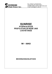
1
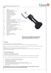
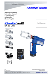
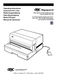
Greenlee Textron/Subsidiary of Textron Inc. 4455 Boeing Drive, Rockford, IL 61109-2988 USA _______________________________________________________________________________________________________________ Bedienungsanleitung für Greenlee Lochstanze Instruction Manual for Greenlee Knockout Punch Driver LS 60 Plus Serialnummer Joh.-Christoph Schütz HE.4439_H 6/97 HE4439_H.doc Anz. der Seiten 27 Bedienungsanleitung LS 60 Plus Seite 2 ________________________________________________________________________________________________________________ Bild/Picture 1 Stanzkopf Pos.-Nr. 3 Befestigungsöse Pos.-Nr. 4 Leuchtdiodenanzeige Pos.-Nr.6 Gehäuse Pos.-Nr. 5 Bedienungsschalter Pos.-Nr. 1 Handschutz Pos.-Nr. 9 Rückstelltaste Pos.-Nr. 2 Akku Pos.-Nr. 7 Bild/picture 2+3 33967 3/4" ADAPTER Nutzen Sie KWIK STEPPER 36018 9,7mm (0,382") f r das BOHRLOCH 03248 DISTANZHÜLSE 30043 3/8" ZUGBOLZEN MATRIZE STEMPEL ZU LOCHENDE BLECHE Nutzen Sie KWIK STEPPER 34411 22,2mm (7/8") f r das BOHRLOCH 3/4" ZUGBOLZEN MATRIZE STEMPEL LOCHER TYP LS60 Bedienungsanleitung LS 60 Plus Seite 3 ________________________________________________________________________________________________________________ Bild/picture 4 29451 7/16" ZUGBOLZEN (OPTIONAL) Nutzen Sie KWIK STEPPER 34411 12,7mm (1/2") f r das BOHRLOCH ZU LOCHENDES BLECH LOCHER TYP LS60 MATRIZE STEMPEL 31874 7/16" AUF 3/4" ADAPTER (OPTIONAL) Bild/picture 5 Falsch/ wrong Richtig/ correct Bild/picture 6 03248 DISTANZH LSE 3/4" ZUGBOLZEN 3/4" ZUGBOLZEN 33967 ADAPTER 30043 ZUGBOLZEN 03248 DISTANZH LSE 31874 ADAPTER 03248 DISTANZH LSE 33967 ADAPTER 29451 7/16" ZUGBOLZEN 29451 7/16" ZUGBOLZEN Bedienungsanleitung LS 60 Plus Seite 4 ________________________________________________________________________________________________________________ Bedienungsanleitung für das Akku-betriebene elektro-hydraulische Stanzgerät Typ LS 60 PLUS, Seriennummer .............................. Inhaltsangabe 1 2 3 4 4.1 4.2 4.3 4.4 4.5 5. 5.1 5.2 5.3 5.4 5.5 5.6 5.7 6 7 8 Einleitung Aufschriften Gewährleistung Beschreibung des elektro-hydraulischen Stanzgerätes Beschreibung der Komponenten Beschreibung der Betätigungsfunktionen Beschreibung des Stanzvorganges Beschreibung der automatischen Steuerung des Stanzvorganges Beschreibung der Leuchtdiodenanzeige Hinweise zum bestimmungsgemäßen Gebrauch Bedienung des Gerätes Erläuterung des Anwendungsbereiches Verarbeitungshinweise Wartungshinweise Ölwechselintervalle Hinweis zur Verwendung des Akkus und des Ladegeräts Aufbewahrung und Transport des Stanzgerätes Verhalten bei Störungen am Stanzgerät Außerbetriebnahme/Entsorgung Technische Daten Kurzinspektion vor Inbetriebnahme Bitte prüfen Sie als erstes, ob Sie alle im Lieferumfang angeführten Teile erhalten haben. Lieferumfang: 1 1 1 2 1 1 1 1 Akku-betriebenes elektro-hydraulisches Stanzgerät Typ LS 60 Plus Akku (schon im Gerät) Ladegerät Zugbolzen 30043 und 03294 Distanzbuchse 03248 Adapter 33967 Vorbohrer 34410 Bedienungsanleitung Bitte prüfen Sie anhand Ihres Lieferscheins, ob Sie auch die von Ihnen gewünschten Stanzeinsätze und ggf. einen Ersatzakku erhalten haben. Bedienungsanleitung LS 60 Plus Seite 5 ________________________________________________________________________________________________________________ 1. Einleitung Vor Inbetriebnahme Ihres Stanzgerätes lesen Sie sich die Bedienungsanleitung sorgfältig durch. • Benutzen Sie dieses Gerät ausschließlich für den bestimmungsgemäßen Gebrauch. • Stanzungen mithilfe dieses Gerätes dürfen nur durch eine elektrotechnisch unterwiesene Person durchgeführt werden. Das Mindestalter beträgt 16 Jahre. • Diese Bedienungsanleitung ist während der gesamten Lebensdauer des Gerätes mitzuführen. • Der Betreiber muß - dem Bediener die Betriebsanleitung zugänglich machen - sich vergewissern, daß der Bediener sie gelesen und verstanden hat. 2. Aufschriften Auf dem an dem Gehäuse angebrachten Typenschild finden Sie Typbezeichnung, Herkunftsangabe und den Firmennamen. Die Seriennummer befindet sich auf dem Hydraulikzylinder zwischen Gehäuse und Stanzkopf. Auf der gegenüberliegenden Seite des Gehäuses befindet sich ein Aufkleber mit einer Kurzdarstellung der stanzbaren Lochdurchmesser für St37 und V2A, der Stanzkraft, der Spannung und Warnhinweisen. Am Stanzkopf befindet sich ein Hinweis auf eine mögliche Verletzungsgefahr bei Stanzvorgängen. 3. Gewährleistung Die Gewährleistung bei sachgemäßer Bedienung und unter Einhaltung der geforderten regelmäßigen Kontrollen des Gerätes beträgt 12 Monate ab Lieferdatum. Bedienungsanleitung LS 60 Plus Seite 6 ________________________________________________________________________________________________________________ 4 Beschreibung des elektro-hydraulischen Stanzgerätes 4.1 Beschreibung der Komponenten Das elektro-hydraulische Stanzgerät mit unserer Typbezeichnung LS 60 PLUS ist ein handgeführtes Gerät und besteht aus folgenden Komponenten: Tabelle 1 Pos.-Nr. 1 2 3 Bezeichnung Bedienungsschalter Rückstelltaste Stanzkopf 4 Befestigungsöse 5 Gehäuse 6 7 Leuchtdiodenanzeige Akku 8 9 Handschutz 10 Stanzeinsätze Funktion Auslösung des Stanzvorgangs Taste zum Rückstellen des Druckrings Kopf zur Aufnahme des Zugbolzens einschließlich Stempel und Matrize Öse zum Transport und Sicherung der Stanze Kunststoffgehäuse mit abschraubbarem Gehäusedeckel Kontrollinstrument zur Funktions- und Fehlerdiagnose wiederaufladbarer 2,6Ah NiMH-Akku (RA4) Bügel zum Schutz der bedienenden Hand und zum Schutz gegen unbeabsichtigtes Auslösen des Bedienungsschalters bestehend aus Stempel und Matrize zum Stanzen der Löcher Referenz S4, 7 S4, 12 S6, 10 S3 S4, 10 S5, 11 S4, 5, 10-13 S3 S4, 7-9, 11, 12 Legende: S = Seite, respektive Seiten 4.2 Beschreibung der Betätigungsfunktionen Ein Stanzvorgang wird durch die Betätigung des Bedienungsschalters (Pos.-Nr. 1) ausgelöst. Das elektro-hydraulische Stanzgerät Typ LS 60 Plus ist mit einer speziellen Schaltung ausgestattet, die den Motor nach erfolgter Stanzung selbständig abschaltet. Der Bedienungsschalter (Pos.-Nr. 1) muß während des Stanzvorganges kontinuierlich gedrückt werden. Das Gerät ist mit einem Nachlaufstop ausgerüstet, der den Vorschub nach Loslassen des Bedienungsschalters sofort stoppt. Durch einmaliges Drücken der Rückstelltaste (Pos.-Nr. 2) kann der Druckring wieder in seine Ausgangsposition zurückgefahren werden. 4.3 Beschreibung des Stanzvorganges Der Stanzvorgang wird gekennzeichnet durch das Einziehen des Stempels in die Matrize. Dabei befindet sich das zu bearbeitende Blech zwischen Stempel und Matrize. Um einen Stanzvorgang einleiten zu können ist es erforderlich, daß der Stempel so an das zu lochende Blech herangeschraubt wird, daß ein Kontakt zwischen Stempel und Blech gegeben ist. Diese Forderung leitet sich von einer integrierten Mikroprozessor-Steuerung ab, die u.a. auf diese Weise sicherstellt, daß für den Stanzvorgang der gesamte Hub zur Verfügung steht. Hat der Anwender den Stempel nicht bis an das Blech herangeschraubt, schaltet sich das Gerät kurz nach der Auslösung automatisch ab. Bedienungsanleitung LS 60 Plus Seite 7 ________________________________________________________________________________________________________________ Nach Auslösung des Bedienungsschalters wird relativ zum lochenden Blech der Stempel bestimmungsgemäß in das Blech eingezogen, wobei sich der Grundkörper um den entsprechenden Hub vom Blech wegbewegt. Diese Bewegung kann durch das Ausfahren des Druckrings optisch verfolgt werden. Ein Stanzvorgang ist abgeschlossen, wenn die Stanzeinsätze ineinander gefahren sind. Zu diesem Zeitpunkt muß der Bedienungsschalter losgelassen werden, um eine Beschädigung des Stempels, bzw. der Matrize, auszuschließen. Anschließend läßt sich der Stempel werkzeugseitig aus dem Blech herausziehen läßt. Diese Abschaltung wird bei Blechstärken > 1,0 mm automatisch durch die Mikroprozessorsteuerung vorgenommen. Bei dünnen Blechen und bei weichen Werkstoffen (z.B. Kunststoffe) ist die automatische Abschaltung nicht immer gewährleistet und der Bediener muß das Gerät manuell abschalten. Sollte während des Stanzvorganges das Überdruckventil auslösen, so wurde die maximal zulässige Kraft überschritten und der Stanzvorgang ist sofort abzubrechen. Durch einmaliges Drücken der Rückstelltaste (Pos.-Nr. 2) fährt der Druckring selbständig in die Ausgangsposition zurück. Nachdem die Blechreste aus der Matrize entfernt worden sind, kann ein weiterer Stanzvorgang vorgenommen werden. 4.4. Beschreibung der automatischen Steuerung des Stanzvorgangs Die LS 60 PLUS ist mit einer Mikroprozessor-Steuerung ausgestattet, die den Ablauf einer Stanzung steuert. Die Lochstanze schaltet sich automatisch ab, wenn nicht innerhalb von etwa 1,5 Sekunden nach dem Einschalten ein Stanzvorgang beginnt. Das ist der Fall, wenn der Stempel nicht nah genug an das Blech herangeschraubt wurde. Durch das automatische Abschalten wird der Bediener auf diesen Fehler aufmerksam gemacht. Außerdem wird durch die Vermeidung des unnötigen Leerlaufs Akkuladung gespart. Nach vollendetem Stanzvorgang, also wenn der Stempel das Blech durchtrennt hat, schaltet sich der Motor der Lochstanze automatisch ab. Diese Funktion dient der Sicherheit des Bedieners und schont die Stanzwerkzeuge. Ohne diese Sicherheitsfunktion kann es leicht passieren, daß der Stempel den Grund der Matrize mit voller Kraft berührt. Dadurch werden die Schneiden des Stempels beschädigt. Im schlimmsten Fall kann die Matrize dabei auseinanderbrechen. Bedienungsanleitung LS 60 Plus Seite 8 ________________________________________________________________________________________________________________ 4.5 Beschreibung der Leuchtdiodenanzeige Die Leuchtdiode (Pos.-Nr. 6) dient in Verbindung mit der Steuerungselektronik zur Information über den Zustand des Akkus (Pos.-Nr. 7) und des Werkzeuges. Im einzelnen leuchtet die Diode in folgenden Fällen: Signal 1 2 5 Dauer wenige Sekunden Blinken 20 Sekunden Dauerleuchten 20 Sekunden Blinken (2Hz) 20 Sekunden Blinken (5Hz) 20 Sekunden Leuchten und Blinken Zeitpunkt beim Einsetzen des Akkus Nach dem Arbeitsvorgang Nach dem Arbeitsvorgang Während der Dauer der Übertemperatur Nach dem Arbeitsvorgang Bedeutung Durchführung des Selbsttests Akku leer Fehler oder Wartung fällig Gerät zu heiß Wartung fällig und Akku leer Hinweise zum bestimmungsgemäßen Gebrauch 5.1 Bedienung des Gerätes Als erstes wird der zueinander passende Stanzeinsatz (Stempel und Matrize) bereitgelegt. Achtung Es dürfen nur original Greenlee Komponenten verwendet werden, da es bei Fremdkomponenten zu Materialversagen kommen kann wodurch umstehende Personen verletzt werden können. Bestimmen Sie den genauen Ort für das Loch. Verwenden Sie den Greenlee KwikStepper Stufenbohrer und bohren Sie ein Loch, das etwas größer ist als der Zugbolzen. Vergewissern Sie sich, daß der Druckring auch vollständig zurückgefahren ist. Achtung Beim Bohren und beim Stanzen Schutzbrille tragen. Abhängig von dem zu stanzenden Lochdurchmesser und Blechstärke sind folgende Zusammenstellungen, bzw. Kombinationen möglich. (siehe Bild 2-4) Achtung Nicht mit unvollständig aufgeschraubtem Gewinde lochen. 1 2 Anmerkungen: - Blinkt die Leuchtdiode ab einem bestimmten Zeitpunkt immer am Ende eines Arbeitsvorgangs für etwa 20 Sekunden, dann ist eine Wartung fällig. Das Gerät ist baldmöglichst ins Werk einzuschicken. - Beim Auftreten eines Fehlers blinkt die Leuchtdiode gleichfalls am Ende eines Arbeitszykluses. Das Blinken zeigt in diesem Fall das Ansprechen der elektronischen Sicherung an. Eine mögliche Ursache dafür ist der Versuch, einen Zyklus mit einem unzulässig entleerten Akku durchzuführen. Tritt das Blinken auch nach Auswechseln des Akkus weiterhin auf, liegt eine andere Störung vor oder eine Wartung ist fällig. In diesen Fällen ist das Gerät ins Werk einzuschicken. Wird das Gerät zu heiß schaltet sich das Gerät selbständig ab. Nach Absinken der Temperatur ist das Gerät automatisch wieder einsatzbereit. Bedienungsanleitung LS 60 Plus Seite 9 ________________________________________________________________________________________________________________ Wenn das Gewinde beispielsweise des Stempels nicht vollständig auf den Zugbolzen aufgeschraubt werden kann, so muß der Aufbau wieder demontiert und die Distanzbuchse entfernt werden. Stellen Sie darüberhinaus sicher, daß die Schneidseite des Stempels dem Blech zugewand ist. Achtung Der Stempel muß so aufgeschraubt werden, daß er schon leichten Kontakt mit dem Blech hat. (siehe Bild 5) Achtung Bei der Montage der Bolzen für Quadratlocher darf ausschließlich die dem Innendurchmesser des Druckrings angepaßte Seite des Zugbolzens eingeschraubt werden. Bei Nichtbeachtung wird der Druckring auf den Bolzen aufgeschoben, verklemmt und kann nicht mehr zurückgefahren werden. Durch diese Fehlbedienung wird der Druckring beschädigt und muß ausgetauscht werden. Nun wird, wie in Kap. 4.3. beschrieben, der Stanzvorgang durchgeführt. Zum besseren Verständnis der Abläufe und Funktionen des Gerätes wird dringend empfohlen, die Kap. 4.4 und 4.5 aufmerksam zu lesen. Achtung Stellen Sie sicher, daß sich während des Stanzens keine Personen vor oder in der unmittelbaren Nähe des Stempels aufhalten, da diese Personen im Falle eines Materialversagens durch herumfliegende Splitter verletzt werden können. Achtung Während des Stanzvorganges nicht mit den Händen in den Stanzbereich eingreifen, da dies zu Quetschungen und Abscherungen führen kann. Achtung Das Gerät schaltet selbständig ab nachdem der Stanzvorgang beendet wurde. Dazu muß der Bedienungsschalter kontinuierlich gedrückt gehalten werden, bis der Stanzvorgang automatisch beendet wird. Bei Blechstärken ≤ 1 mm oder weichen Werkstoffen (z.B. Kunststoffe) muß der Bediener das Gerät durch Loslassen des Bedienungsschalters nach dem Durchstanzen abschalten. Achtung Das Gerät darf nach dem Durchlochen/Abschalten nicht erneut betätigt werden, da es ansonsten zu einem Kontakt zwischen Stempel und Matrize kommen kann. Es kann dabei zu einem Bruch der Locher kommen und Personen können durch herumfliegende Splitter verletzt werden. Der Stempel und die Matrize müssen demontiert und die Blechreste entfernt werden. Achtung Der Stanzvorgang kann jederzeit durch Loslassen des Bedienungsschalters unterbrochen werden. Achtung Vor Auswechselung der Stanzeinsätze unbedingt Akku gegen unbeabsichtigtes Betätigen aus dem Gerät entfernen. Bedienungsanleitung LS 60 Plus Seite 10 ________________________________________________________________________________________________________________ 5.2. Erläuterung des Anwendungsbereiches Unser elektro-hydraulisches Stanzgerät vom Typ LS 60 PLUS verfügt über eine große Anzahl verschiedener Stanzeinsätze (Pos.-Nr. 10) zum Lochen unterschiedlicher Lochgeometrien und unterschiedlicher Materialien wie z.B. St 37 und Chrom-Nickel Stählen (V2A, V4A). Die folgende Tabelle gibt die Obergrenzen der zu stanzenden Lochgrößen wieder: Tabelle 2 Material St 37 Blechstärke 2,5 mm St 37 3,0 mm St 37 Rostfrei (V2A) 3,5 mm 3,0 mm Typ Rundlocher bis ∅ 96 mm (Standard) Quadratlocher 92 mm x 92 mm Rechtecklocher 46 mm x 92 mm Rundlocher bis ∅ 64 mm (Slug Buster) Quadratlocher 68 mm x 68 mm Rundlocher bis ∅ 64 mm (Slug Buster) Rundlocher bis ∅ 60 mm (Slug Splitter) Bei nicht von dieser Tabelle erfaßten Kombinationen bei denen Sie Zweifel an der Stanzbarkeit haben, empfehlen wir eine Rücksprache mit unserem Service Center. In Bild 6 können Sie eine Auswahl der verfügbaren Zugbolzen, Distanzringe und Adapter ansehen. Achtung Es dürfen nur die zum bestimmungsgemäßen Gebrauch vorgesehenen Materialien gelocht werden. Sollten andere Materialien gestanzt werden müssen, ist eine Rücksprache mit dem Werk zwingend erforderlich. Achtung Desweiteren dürfen keine unter Spannung stehenden Teile gestanzt werden. Vor Arbeitsbeginn ist ein spannungsfreier Zustand des Arbeitsumfeldes (z.B. Schaltkastens) oder der zu lochenden Bleche sicherzustellen. Bei dem LS 60 PLUS handelt es sich um ein handgeführtes Gerät das nicht eingespannt werden darf. Es darf nicht für den stationären Einsatz verwendet werden. Das Gerät ist nicht für den Dauerbetrieb geeignet. Es muß nach ca. 40 Stanzvorgängen hintereinander eine kurze Pause von mindestens 15 min eingelegt werden, damit dem Gerät Zeit zur Abkühlung gegeben wird. Achtung Bei zu intensivem Gebrauch kann es durch Erhitzung zu Schäden am Gerät kommen. Achtung Beim Betrieb von Elektromotoren kann es zur Funkenbildung kommen, durch die feuergefährliche oder explosive Stoffe in Brand gesetzt werden können. Bedienungsanleitung LS 60 Plus Seite 11 ________________________________________________________________________________________________________________ Achtung Das elektro-hydraulische Stanzgerät darf nicht bei starkem Regen oder unter Wasser eingesetzt werden. 5.3. Verarbeitungshinweise Der Greenlee Gator LS 60 PLUS ist ein handgehaltenes akkubetriebenes Lochstanzgerät zum Stanzen von unterschiedlichen Löchern in Kunststoff, Fiberglas, Aluminium und Stahl. Die LS 60 PLUS kann mit folgenden Greenlee Stanzeinsätzen betrieben werden: * * * * Standard Locher, bestehend aus Stempel, Matrize und Zugbolzen Slug-Buster Locher, bestehend aus Stempel, Matrize und Zugbolzen Slug-Splitter Locher, bestehend aus Stempel, Matrize und Zugbolzen Sonderlocher für elektronische Anschlüsse, bestehend aus Stempel, Matrize und Zugbolzen Mit den Standard, Slug Buster und Sonderlochern können Löcher in Kunststoff, Fiberglas, Aluminium und Stahl gemacht werden. Mit den Slug-Splitter Lochern können all die vorgenannten Materialien gelocht werden und zusätzlich noch rostfreie Stähle. 5.4. Wartungshinweise Das Preßgerät ist nach jedem Gebrauch zu reinigen und trocken zu lagern. Sowohl Akku als auch Ladegerät müssen vor Feuchtigkeit und vor Fremdkörpern geschützt werden. Das Gerät ist prinzipiell wartungsfrei. Lediglich die durch die Schaltung angezeigten Wartungsintervalle müssen eingehalten werden. Im Rahmen des bestimmungsgemäßen Gebrauchs dürfen vom Kunden nur die Stanzeinsätze (Pos.-Nr. 10) gewechselt werden. Achtung Geräteversiegelung nicht beschädigen! Bei Beschädigung der Geräteversiegelung erlischt der Garantieanspruch. 5.5. Hinweis zur Verwendung des Akkus und des Ladeteils Das Ladegerät ist für Wechselspannung von 230 V mit einer Frequenz von 50 Hz ausgerüstet. Neue Akkus müssen vor dem erstmaligen Gebrauch geladen werden. Zur Aufladung des Akkus wird der Stecker des Ladegerätes in die Steckdose und der Akku in das Ladegerät eingesteckt. Die Ladezeit beträgt ca. eine Stunde. Der Ladezustand des Akkus kann an einer Leuchtdiode am Ladegerät abgelesen werden. grün: rot: blinken: Akku ist aufgeladen Akku ist leer und wird gerade geladen. Akku nicht vollständig eingeschoben oder Akku zu heiß, ein akustisches Signal ertönt. Schieben Sie den Akku so in das Gerät, daß die Plus- und Minuspole an der Batterie denen am Lader entsprechen. Ist der Akku richtig angeschlossen, so wechselt das Ladelicht von grün auf rot und der Ladevorgang beginnt. Ist der Ladevorgang Bedienungsanleitung LS 60 Plus Seite 12 ________________________________________________________________________________________________________________ abgeschlossen wechselt das Ladelicht wieder auf grün, wobei gleichzeitig ein Piepton 5 Sekunden lang abgegeben wird. Es dürfen keine artfremden Akkus z.B. Trockenbatterien oder Autobatterien etc. weder in der Presse noch im Ladegerät verwendet werden. Laden Sie Ihren Akku auf, sobald die Geschwindigkeit Ihrer Maschine merklich nachläßt. Laden Sie nicht vorsichtshalber einen teilentladenen Akku nach. Wenn Sie einen Akku aus einem kürzlich betriebenen Gerät oder einen, der längere Zeit in der Sonne lag, laden, kann das Aufladelicht rot blinken. Warten Sie in diesem Fall eine Weile. Das Aufladen beginnt nach Abkühlung des Akku. Blinkt das Aufladelicht abwechselnd rot und grün und wird ein Piepton 20 sec. lang abgegeben, ist das Aufladen nicht möglich. Die Pole des Ladegerätes oder die des Akkus sind durch Staub verschmutzt oder der Akku ist verbraucht oder beschädigt. Wollen Sie zwei Akkus hintereinander aufladen, warten Sie 15 min bevor Sie den zweiten Akku laden. Vermeiden Sie starke Temperaturschwankungen unter 0°C und über 40°C. Dadurch können Beschädigungen sowohl am Akku als auch an der Presse auftreten. Die optimale Betriebstemperatur liegt zwischen 15 und 25 °C. Lassen Sie das Ladegerät nie im Regen oder Schnee liegen. Laden Sie den Akku nicht in Anwesenheit leicht entzündbarer Stoffe oder Gase. Tragen Sie das Ladegerät nie am Netzkabel und ziehen Sie es nicht gewaltsam aus der Steckdose heraus. Stecken Sie keine fremden Gegenstände in die Lüftungsgitter des Ladegerätes. Achtung Stecken Sie den Akku nicht in Ihre Hosentasche oder in Ihre Werkzeugkiste wenn sich in ihnen leitfähige Teile befinden, wie z.B. Münzen, Schlüssel, Werkzeuge oder andere metallische Teile. Das Laden der Akkus darf nur in den vom Hersteller vorgeschriebenen Ladegeräten vorgenommen werden. Ziehen Sie das Ladegerät nach dem Laden aus der Steckdose heraus. Nehmen Sie das Ladegerät nicht auseinander. Um die Sicherheit und Zuverlässigkeit des Ladegerätes zu gewährleisten sollten Reparatur, Wartung oder Einstellung durch unser Service-Center durchgeführt werden. 5.6. Aufbewahrung und Transport des Stanzgerätes Um das Stanzgerät vor Beschädigungen zu schützen, muß das Stanzgerät nach Gebrauch und nachdem es gesäubert worden ist, in den Transportkoffer gelegt werden, der dann anschließend sicher zu verschließen ist. In diesem Koffer finden desweiteren ein Ersatzakku, das Ladegerät, 9 Stanzeinsätze, zwei Zugbolzen, 1 Adapter, 1 Distanzbuchse, 1 Vorbohrer und die Betriebsanleitung platz. Bedienungsanleitung LS 60 Plus Seite 13 ________________________________________________________________________________________________________________ 6. Verhalten bei Störungen am Stanzgerät a.) Regelmäßiges Blinken der Leuchtdiodenanzeige (Pos.-Nr. 6) => Akku (Pos.-Nr. 7) austauschen. Leuchtet die Anzeige weiter, muß das Gerät eingeschickt werden. (siehe auch Kap. 4.3) b.) Das Preßwerkzeug verliert Öl. => Das Gerät einschicken. Das Gerät nicht öffnen und die Geräteversiegelung nicht beschädigen. c.) Preßwerkzeug erreicht die erforderliche Stanzkraft nicht. => Preßvorgang unterbrechen. Rückstelltaste (Pos.-Nr. 2) gedrückt halten und gleichzeitig Bedienungsschalter ca. 10 sec. dauerbetätigen. Wird der Fehler dadurch nicht behoben, muß das Gerät ins Werk eingeschickt werden. d.) Fehleranzeige durch Leuchtdiodenanzeige Siehe Kapitel 4.5 (Fehleranzeige) 7. Außerbetriebnahme/Entsorgung Auch bei qualitativ hochwertigen Geräten ist irgendwann der Zeitpunkt gekommen, an dem die Entsorgungsfrage gestellt werden muß. Die Entsorgung der einzelnen Komponenten des Aggregates muß getrennt erfolgen. Dabei muß zuerst das Öl abgelassen werden und an speziellen Abnahmestellen entsorgt werden. Achtung Hydrauliköle stellen eine Gefahr für das Grundwasser dar. Unkontrolliertes Ablassen oder unsachgemäße Entsorgung steht unter Strafe. (Umwelthaftungsgesetz) Als nächstes muß der Akku speziell unter Berücksichtigung der Batterieverordnung entsorgt werden. Bei der Entsorgung der restlichen Teile des Aggregates beachten Sie bitte die EGUmweltstandards. Wir empfehlen wegen möglicher Umweltverschmutzung die Entsorgung durch zugelassene Fachunternehmen vornehmen zu lassen. Achtung Das Gerät darf nicht als Einheit im Restmüll entsorgt werden, da es auf der Deponie Umweltschäden verursachen kann. Eine kostenfreie Rücknahme des Altgerätes durch den Hersteller kann nicht zugesagt werden. Bedienungsanleitung LS 60 Plus Seite 14 ________________________________________________________________________________________________________________ 8. Technische Daten Gewicht des Gerätes mit Akku: Stanzkraft: Antriebsmotor: Motorspannung: Akkukapazität: Akku-Ladezeit: Stanzzeit: Kapazität: Hydrauliköl: Umgebungstemperatur: Schalldruckpegel: Vibrationen: 3,7 kg ca. 60 kN Gleichstrom-Permanentfeldmotor 12 V DC 2,6 Ah [RA4] ca. 1 h [LG 4], bzw. ¼ h [LG5] 5 s bei ∅ 22,5 mm, 3 mm St37 12 s bei ∅ 61,5 mm, 3 mm St37 • 90 Stanzungen/Akku bei ∅ 22,5 mm und 3,4 mm Bleche St 37, bzw. • 170 Stanzungen/Akku bei ∅ 22,5 mm und 3 mm Bleche St 37 bzw. • 250 Stanzungen/Akku bei ∅ 22,5 mm und 2,5 mm Bleche St 37 65 ml "Shell Tellus T 15" -20°C bis +40°C 70 dB (A) in 1m Abstand < 2,5 m/s² (gewichteter Effektivwert der Beschleunigung) Maße: Kolbenhub: Außendurchmesser des Kopfes: Länge Kopf und Gehäuse: ∼ mit ausgefahrenem Druckring: Gesamthöhe: Breite: 22 mm 54 mm 262 mm 284 mm 292 mm 79 mm Symbole Sicherheitstechnische Hinweise Bitte unbedingt beachten, um Personenund Umweltschäden zu vermeiden. Anwendungstechnische Hinweise Bitte unbedingt beachten, um Schäden am Gerät zu vermeiden. Anmerkung Diese Bedienungsanleitung kann kostenlos unter der Bestell-Nr. HE.4439_H nachbestellt werden. Instruction Manual for the electric-hydraulic punching unit Type LS 60 PLUS, Serial-No. .............................. Index 1. 2. 3. 4. 4.1. 4.2. 4.3. 4.4. 4.5. 5. 5.1. 5.2. 5.3. 5.4. 5.5. 5.6. 5.7. 6. 7. 8. Introduction Labels Warranty Description of the electric-hydraulic punching unit Description of the components Description of the operating functions Description of the punching process Description of the automatic control of the punching procedure Description of the light diode display Remarks in respect of the determined use Operation of the units Explanation of the application range Mounting instructions Service and maintenance instructions Remarks on the use of the battery cartridge and charger Storage and transport of the punching unit. Reference as to which (spare-) parts can be exchanged by the customer Troubleshooting Putting out of operation/waste disposal Technical data Brief inspection before putting into service Please check immediately if you received all parts mentioned in our basic supply. Basic supply: 1 1 1 2 1 1 1 1 Electric-hydraulic punching unit Type LS 60 PLUS Battery cartridge (plugged in the unit) Charging unit Draw Studs 30043 and 03294 Spacer 03248 Adapter 33967 Step bit 34410 Instruction manual Please check according your bill of delivery if you received all requested punches and e.g. a spare battery cartridge. Joh.-Christoph Schütz HE.4439_H 6/97 HE4439_H.doc Anz. der Seiten 27 Instruction Manual LS 60 Plus page 16 ________________________________________________________________________________________________________________ 1. Introduction Attention Before starting to use the tool please read the instruction manual carefully. • Use this tool exclusively for its determined use. • Punching holes with the help of this tool must only be performed by specially trained personnel. The minimum age is 16 years. • This instruction manual has to be carried along during the entire life span of that tool. • The operator has - to guaranty the availability of the instruction manual for the user and - to make sure, that the user has read and understood the instruction manual. 2. Labels On the labels fixed on the housing of the tool you’ll find the type specification, name of the manufacturer and the company logo. On the opposite side of the housing you’ll find a label with a brief presentation of the scope of manageable hole diameters in metal sheets made of mild steel and stainless steel and the punching force. The serial number is located on the hydraulic cylinder. On the punching head you’ll find a warning against possible injuries during the punching process. 3. Warranty If correct operation is guaranteed and regular service is provided our warranty is 12 months from the time of delivery. Instruction Manual LS 60 Plus page 17 ________________________________________________________________________________________________________________ 4. Description of the electric-hydraulic punching unit 4.1. Description of the components The electric-hydraulic punching unit type LS 60 PLUS is a hand held tool and consists of the following components: Table 1 (see picture 1) Pos.-No. Description 1 Trigger 2 Retract button 3 Punching head 4 5 6 7 8 9 10 Function Button to initiate the punching process Button to retract the ram by a single touch Pressure ring with reception for draw stud, die and punch Fastening ring Ring for transportation and safety device for the unit Lid Detachable plastic lid fixed on the housing Light diode Indicator for tool functions and battery display charge control Battery cartridge Rechargeable 12V 2,6Ah NiMH battery (RA4) Hand guard Removable guard to protect the operating hand and the trigger to avoid unintended operations Knockout punch Interchangeable punching dies Reference pp pp pp pp p pp pp p pp 4.2. Description of the operating functions The punching procedure is initiated by actuating the trigger (Pos.-No. 1). The electric hydraulic punching unit type LS 60 PLUS is equipped with a special circuit board which automatically stops the punching procedure at the end of an punching cycle. The trigger must be actuated continuously during the punching procedure. The unit is supplied with a special brake which stops the forward motion of the piston after having released the trigger. Push retract button (Pos.-No. 2) once to return the piston into starting position. For more information on the special features of the circuit board please see chapter 4.4. 4.3. Description of the punching processes The punching process is defined by the penetration of the punch into the die. The material being punched is between the die and the punch. To initiate the punching process it is mandatory to screw the punch up to the sheet until they contact each other. This claim derives from the integrated microprocessor which by this guaranties that the entire stroke is available for the punching process. If the distance between the punch and the sheet is too far the tool will automatically stop. After actuating the trigger the punch will be drawn into the sheet and the tool will simultaneously move away from the sheet up to the stroke length of 22 mm. This movement can be visualised by the drive-out of the pressure ring. The punching cycle is terminated when the punch has completely penetrated the die. Afterwards the punch can be pulled through and away from the sheet. Instruction Manual LS 60 Plus page 18 ________________________________________________________________________________________________________________ By actuating the retract button (Pos.-No. 2) once the pressure ring returns automatically into the starting position. After the remains of the sheet has been removed from the die the next punching cycle can be initiated. The automatic switch-off is controlled by the microprocessor when punching holes bigger than 1 mm. Punching thin sheets and soft materials (e.g. plastics) the automatic switch off can not be guaranteed and the user must switch off the unit manually. If the relief valve should open during the punching process the max. punching force has been reached and the punching process has to be terminated. In this case an automatic retraction returns the pressure ring into the starting position. 4.4. Description of the automatic control of the punching procedure The LS 60 PLUS is equipped with a microprocessor controlling the procedure of punching cycles. The punching unit switches off automatically if the punching cycle does not start within 1,5 sec. This is the case when the punch is not screwed close enough to the sheet intended to be punched. The controller should make the user aware of this mistake. On top of that this avoids unnecessary idle saving battery power. After a punch is completed that means when the puncher completely penetrated the die the unit also switches off automatically. This function serves the safety of the user and prevents a fatal contact between the puncher and the die. Without this safety feature it can easily happen that the puncher is driven into the die with full strength destroying both puncher and die. 4.5. Description of the light diode display This tool is equipped with a special circuit board incorporating several important features to inform the user about the current status of the unit. The diode (Pos.-No. 6) signals in the following cases: Signal 1 2 1 Duration a few seconds of flashing glowing for 20 seconds flashing for 20 seconds (2Hz) flashing for 20 seconds (5Hz) 20 sec. glowing and flashing intermittently When it occures battery insertion What it means self check – O.K. after crimp battery discharged after crimp return for service During high temperature after crimp unit too hot service required and battery flat Remarks: - Does the diode signal periodically at the end of a working cycle for approx. 20 sec the unit must be returned to an authorised Service Center for Service as soon as possible. - In case of an error the light diode display also signals periodically at the end of a working cycle. The signal indicates in this case the circuit opening by the electronic fuse. A possible reason for that is that a cycle was performed with an incorrectly low battery. If the signal occurs even after changing the battery there must be a different error or a service is due. In these cases the tool must be returned to the manufacturer or an authorised service center. 2 The unit switches off when it gets too hot. It switches on automatically after the unit cooled off. Instruction Manual LS 60 Plus page 19 ________________________________________________________________________________________________________________ 5. Remarks in respect of the determined use 5.1. Operation of the units First you have to select the appropriate punch set for the intended application. Attention Don’t use other than genuine Greenlee components because other manufacture’s components may not withstand the forces generated by punch driver. This could result in component failures and hurt nearby personnel. Determine the exact location of the hole. Use a Greenlee Kwik-Stepper step bit and drill a hole which is a little bit bigger than the outside diameter of the draw stud you are using. Please make sure that the pressure ring is completely retracted. Attention Use eye protection when using the Greenlee Kwik-Stepper and our punch driver. The following combinations are conceivable dependent on the punchable hole diameters and sheet thickness: (see picture 2-4) Attention Do not punch with threads not completely engaged. If any of the punch threads are not engaged with the threads of the draw stud, disassemble the set-up, remove the spacer and reassemble the set-up. Please make sure that cutting surfaces of the punch face the material. Attention The punch must be screwed on the draw studs until puncher and sheet contact each other. (please see picture 5) Attention When assembling draw studs for square punches only the adapted side of the draw stud corresponding with the pressure ring should be screwed into the punch head. The punching process will proceed as described in chapter 4.3. Please see also chapter 4.4. and 4.5 for further information on the features of the tool and diode functions. Attention Do not allow anyone to stand directly in front of the punch. A component failure could propel parts that could strike nearby personnel Attention Keep hands away from the punch, die and draw stud during operation Attention The unit shuts off automatically after it senses that the punch is completely through the material The trigger (Pos.-No. 1) must be actuated continuously until the punching cycle is terminated automatically. When punching metal sheets ≤ 1 mm or soft materials (e.g. plastics) the user must release the trigger after the punch is completed. Instruction Manual LS 60 Plus page 20 ________________________________________________________________________________________________________________ Attention After the punch has been completed the trigger should not be actuated again because that can result in an contact between die and matrice. Both components may break and strike nearby personnel. Die and Matrice have to be disassembled and the remains must be removed. Attention The punching process can be interrupted at any moment by releasing the trigger. Attention Before changing punch and die remove battery to avoid unintended use. 5.2. Explanation of the application range Our electric-hydraulic punching tool type LS 60 PLUS has a large number of punches and dies available to punch holes in various materials such as St 37, stainless steel and others. The following table lines out the upper limits of the punchable hole diameters: Table 2 Material St 37 St 37 St 37 stainless steel (V2A) Sheet thickness Type 2,5 mm Round puncher up to ∅ 96 mm (Standard) Square puncher 92 mm x 92 mm Rectangular puncher 46 mm x 92 mm 3,0 mm Round puncher up to ∅ 64 mm (Slug Buster) Square puncher 68 mm x 68 mm 3,5 mm Round puncher up to ∅ 64 mm (Slug Buster) 3,0 mm Round puncher up to ∅ 60 mm (Slug Splitter) For combination not covered by this table where you have any doubts in the punchability we recommend to contact our Service Center for advice. In picture 6 you can see a selection of available draw studs, spacer and adapter. Attention Do only punch holes into materials acc. to the determined use If materials than those mentioned in chapter 5.3 have to be punched, please contact the manufacturer. Attention Do not punch parts which might be connected to live cables or conductors Before starting to punch please make sure that all parts involved in the punching process are not connected to live circuits. The LS 60 PLUS is a hand held tool and it is not supposed to be restrained in a vise. It is not allowed to use the tool in a stationary application. The tool is not designed for continued punching cycles. After a sequence of approximately 40 consecutive and completed punches you have to make a break of a quarter of an hour to give the tool time to cool down. Instruction Manual LS 60 Plus page 21 ________________________________________________________________________________________________________________ Attention Too intensive use can cause heat damages for the tool Attention During the operation of electric engines sparks can occur which might ignite highly inflammable or explosive liquids and materials Attention Electric-hydraulic punching tools should not be operated in pouring rain or under water. 5.3. Mounting instructions The Greenlee Gator is a hand held battery powered punching unit to punch holes in various different Materials such as plastic, fibre glass, aluminium and steel. The LS 60 PLUS is designed to be used with the following Greenlee accessories: • • • • Standard punches, dies and draw studs Slug-Buster punches, dies and draw studs Slug-Splitter punches, dies and draw studs Electronic Connector Panel Punches Standard, Slug-Buster and Electronic Panel Punches can punch holes through plastic, fibreglass, aluminium and steel; Slug-Splitter punches, dies and draw studs are capable of punching through all of these materials and stainless steel. 5.4. Service and maintenance instruction The electric-hydraulic punching unit is equipped with a sophisticated circuit board enabling the user to see when the next service is due. (Pls. read chapter 4.4 for more information) When the next service is due the unit needs to be returned to an authorised service center (ASC). For every day service the unit has to be cleaned and dried after each use. The battery cartridge and the charging unit have to be protected against humidity and dust. 5.5. Remark on the battery cartridge and charging unit. The charging unit is run with a nominal voltage of 230 V and a frequency of 50 Hz. New battery cartridges must be completely charged before being used. To charge the battery cartridge (Pos.-No. 7) the power plug of the charging unit has to be plugged into the power supply and the battery cartridge has to be pushed into the charging unit. The charging time is one hour. The charging level of the battery cartridge can be checked by a LED. green red flashing battery cartridge is charged Battery cartridge is empty and is just being charged battery cartridge is not pushed in properly or is too hot, a sound signal occurs Push the battery into the charging unit so that the polarity of the poles of the battery corresponds to those at the charger. Is the battery plugged in correctly the LED changes from green to red and the charging procedure starts. When the charging procedure is terminated the LED changes again to green. Simultaneously a signal occurs for 5 seconds. Instruction Manual LS 60 Plus page 22 ________________________________________________________________________________________________________________ No other battery cartridges e.g. dry batteries or car batteries etc. are permitted to be used neither in the tool nor in the charging unit. As soon as the speed of the machine decreases noticeably the battery must be recharged. Do not recharge a partially empty battery as a precaution. If charging a battery which has currently been used or which was laying in the sun for a longer period of time the LED might flash red. In this case wait for a while. The charging procedure starts after the battery cooled down. Does the LED flash red and green and does an audible tone occur for 20 seconds it is not possible to charge that battery. The poles of the battery or the charging unit are dirty or the battery is low or damaged. If you want to charge two batteries in a row wait for 15 min before you charge the second battery. Avoid great fluctuating temperatures under 0°C and above 40°C. Through these fluctuations damages may result for the battery cartridge as well as for the charging unit. The best operation temperature is between 15-25 °C. Do not leave or operate the charging unit in rain or snow. Do not charge the battery near lightly inflammable materials or gases. Do not use the cord to transport the charging unit or to pull the plug out of a wall socket with force. Do not insert strange parts into the ducts of the charging unit. Attention Do not place the battery in your pocket or in your toolbox if there are any conductive materials in it such as coins, keys, tools or other metallic parts. The charging of the batteries must only be done with charging units supplied by the manufacturer. Pull the plug of the charging unit after charging. Do not disassemble the charging unit or battery. In order to safeguard a safe and proper performance of the charging unit the repair and service of the unit should be made through our Service Center. 5.6. Storage and transport of the punching tool In order to protect the tool against damages it has to be cleaned carefully after every use and be put into the transportation case which has to be closed safely. Into this case you can put a spare battery cartridge, the charging unit, 9 punch sets, 2 draw studs, 1 adapter, 1 spacer, 1 step bit and the instruction manual. 5.7. Reference as to which spare parts can be exchanged by the customers Within the determined use of the tool only the Greenlee accessories, the battery cartridge and the oil are permitted to be changed by the customers. Attention Do not damage the seals of the tool. If the seals are damaged, the warranty is invalidated. Instruction Manual LS 60 Plus page 23 ________________________________________________________________________________________________________________ 6. Troubleshooting a.) The pressure ring (ram) comes to a standstill during a punching cycle. => Stop the punching cycle. Hold down the retract button and at the same time actuate the trigger for around 10 seconds. If the malfunction can’t be eliminated the tool has to be returned to the manufacturer. b.) The tool is leaking oil. => Return the tool to the manufacturer. Do not open the tool or remove its seal. c.) Error indicated by the light diode display (Pos.-No. 6) Pls. see chapter 4.5 (Error indication) 7. Putting out of operation/waste disposal After intensive use even a high-quality tool has to be put of operation. The disposal of the various components of the tool have to be treated separately. Doing that the first step is to dispose of the oil at special delivery points. Attention Hydraulic oils represent a danger for the ground-water. Uncontrolled draining of or improper disposal is under penalty. (environmental liability law) Next, the battery cartridge has to be specially disposed of. To dispose of the remaining parts of the unit please consult your national environmental laws. Because of possible environmental damages we recommend to dispose of the tool by professional companies. Attention Do not dispose of the unit in your residential waste because it will finally end up on the waste dump which would be hazardous for the environment. A return of the old tool free of charge to the manufacturer cannot be granted. Instruction Manual LS 60 Plus page 24 ________________________________________________________________________________________________________________ 8. Technical Data Weight of the complete tool: Punching force: Driving motor: Motor voltage: Charging voltage: Battery capacity Charging time: Punching time: Punching speed: Punching performance: Hydraulic oil: Environmental temperature: Sound level: Vibrations: approx. 3,7 kg approx. 60 kN direct-current permanent field motor 12 V DC 12 V 2,6 Ah (RA4) approx. 1 h (LG4), ¼ h with Quickcharger (LG5) approx. 5 s at ∅ 22,5 mm, 3 mm St37 approx. 12 s at ∅ 61,5 mm, 3 mm St37 2,4 mm/s approx. 90 punches/battery at ∅ 22,5 mm and 3,4 mm sheet thickness or approx. 170 punches/battery at ∅ 22,5 mm and 3,4 mm sheet thickness or approx. 250 punches/battery at ∅ 22,5 mm and 2,5 mm sheet thickness ca. 65 ml "Shell Tellus T 15" -20°C to –40°C 70 dB (A) in 1m distance < 2,5 m/s² Dimensions: Piston stroke: Diameter of the punching head: Length head and housing: ~ with a driven out thrust ring: Length of the punching head: Complete height: Width 22 mm 54 mm 262 mm 284 mm 130 mm 292 mm 79 mm Symbols Safety warnings Please do not disregard these instructions in order to avoid human injuries and environmental damages. Operational warnings Please do not disregard them to avoid damaging the pump unit. Note Additional instruction manuals are available free of charge. The part # is HE.4439_H. Service LS 60 plus Seite/page 25 _____________________________________________________________________________________________________________________ Greenlee Service Center DEUTSCHLAND FRANKREICH: Klauke Remscheid Mr. Radtke Auf dem Knapp 46 42855 Remscheid Tel.: ++49 (0)2191/907-168 Fax: ++49 (0)2191/907-242 E-Mail: [email protected] KLAUKE FRANCE M. Weiten 16, Rue Saint-Louis Z.I. Actisud 57150 Creutzwald (France) Tel.: ++33-3-87298470 Fax: ++33-3-87298479 E-MAIL: [email protected] GROSSBRITTANIEN Norwich Instrument Services Mr. Norman Cockburn 32 Hellesdon Park Road Drayton High Road Norwich NR6 5DR (UK) Tel.: 0044-1603-416900 Fax: 0044-1603-416902 E-Mail: [email protected] ISRAEL: Shay A.U., Ltd. Mr. Shay Ind. Zone Kiriat Arieh Embar Street 23/25 P.O. BOX 10049 49222 Petach Tikva (Israel) Tel.: ++972-3-9233601 Fax: ++972-3-9234601 E-MAIL: [email protected] ITALIEN: F.B. Spa Mr. Victor Drozdowski Via Buonarroti, 11 61030 Borgaccio di Soltara (PU) (Italy) Tel.: ++39-0721-892168 Fax: ++39-0721-879602 E-MAIL: [email protected] NIEDERLANDE: H.K. Electric B.V. Mr. van Heek De Steegen 7 5321 JZ Hedel (Niederlande) Tel.: ++31-73-5997599 Fax: ++31-73-5997590 E-Mail: [email protected] ÖSTERREICH: KLAUKE Handelsgesellschaft mbH Mr. Acham Kaiser-Franz-Josef-Str. 9 1230 Wien (Österreich) Tel.: ++43-1-8893436 Fax: ++43-1-8893433 E-MAIL: [email protected] POLEN/ UKRAINE: PORTUGAL: RB Brexim S.A. Marynin 7a 05-825 Grodzisk Mazowiecki (Polen) Tel.: ++48-22-7920273 oder 75 Fax: ++48-22-7923055 E-MAIL: [email protected] Palissy Galvani Electricidade Lda. Ms. Anna Pereira Rua Serpa Pinto, 15-A/P 1200 Lisboa (Portugal) Tel.: ++351-21-3223400 Fax: ++351-21-3223410 E-Mail: [email protected] SLOWENIEN: SPANIEN/ ANDORRA: Isaria d. o.o. Ms. Zorz Proizvdnja in trgovina Cece 2a 1420 Trovlje (Slowenien) Tel.: ++386-356-31800 Fax: ++386-356-3180 E-MAIL: [email protected] Gave Electro S.A. Mr. Fernando Carvalho Paratge Coll-Blanc, S/N Aptdo. 12 08430 La Roca del Valles, Barcelona (Spanien) Tel.: ++34-93-8422212 Fax: ++34-93-8422227 E-MAIL: [email protected] TSCHECHISCHE REPUBLIK/ SLOVAKEI: Jiri Nitsch M. Pujmanove 1220/31 14000 Praha 4 – Prankrac (Tschechische Republik) Tel.: ++42-2-61213220 Fax: ++42-2-61213218 VOLKSREP. CHINA: (lokaler Partner) Guangdong Xueqin Electric Equipment Trading Co. Ltd Ms. Wu Yuwei Room B08, Floor 7, Suifeng Tower, No.75, Xian lie M.Road 510095 Guagzhou (P.R. China) Tel.: ++86-20-87323432 Fax: ++86-20-87327792 E-MAIL: [email protected] (lokaler Partner) Beijing Hawk Hydraulic Mechanical Technology Co. Ltd. Mr. Li Ming 02-B, Building C, Majestic Garden, No.6 Middle Road of the 4 North Ring 100029 Beijing (P.R. China) Tel.: ++86-10-82848120 Fax: ++86-10-82845479 E-MAIL: [email protected] (Service Ansprechpartner) Shanghai Fengye Trading Co. Ltd Mr. Zhang Yulian Room F, No.250, Changning Road, 200042 Shanghai (China ZIP) Tel.: ++86-21-62254404 Fax: ++86-21-62268633 E-Mail: [email protected] KOREA: Taehyung Hydraulic Tool Mr. Kim 140-5, Gamjeun-Dong, Sasang-Gu Busan 17-060 (Korea) Tel.: ++82-51-3171507 Fax: ++82-51-3171507 E-Mail: [email protected] SCHWEDEN Miltronic AB Mr. Thomas Fred Kungshagsvägen 7 S-611 29 Nyköping (Schweden) Tel.: 0046-155-77700 Fax: 0046-155-77702 E-Mail: [email protected] NORWEGEN Miltronic AS Mr. Hans Petter Selbo Dolasletta 5, 4308 Transby N-3421 Lierskogen (Norwegen) Tel.: 0047-32226610 Fax: 0047-32226656 E-Mail: [email protected] Service LS 60 plus Seite/page 26 _______________________________________________________________________________________________________________ UNGARN Trend Elektro Mr. Istvan Imrik H-1117 Budapest Dombovari ut 5-7 (Ungarn) Tel.: 0036-1-464-3118 Fax: 0036-1-464-3119 E-Mail: [email protected] TÜRKEI Ünal Kardes Mr. Servet Diricanli Eski Londra Asfalti No. 6 34630 Desyol-SefaköyIstanbul (Türkei) Tel.: 0090-212-6249204 Fax: 0090-212-5924810 E-Mail: [email protected] Schweden Bulgarien RUSSLAND Unit Mark Pro Mr. Alexander Naichouller 119147 Moscow Marksistskaya 34, bldg 10 (Russland) Tel.: 007-095-7480907 Fax: 007-095-7480909 E-Mail: [email protected] SÜDARFIKA Geplante (planned) Service-Center in 2004/2005: DÄNEMARK BELGIEN AUSTRALIEN RUMÄNIEN: Gerkon S.R.L. Mr. Heim Miercurea Ciuc Str. Eminescu 1 4100 Miercurea Ciuc (Rumänien) Tel.: 0040-266-372108 Fax: 0040-266-112238 e-Mail: [email protected] KROATIEN: Konekt d.o.o. Mr. Dubravko Salkovic Cerinina HR-10000 Zagreb (Kroatien) Tel.: 00385-12361890 Fax: 00385-12361882 E-Mail: [email protected] SCHWEIZ: Ferratec AG Mr. Bürgisser Großmattstr. 19 CH-8964 Rudolfstetten Tel.: 0041-56-6492121 Fax: 0041-56-6492141 E-Mail: [email protected] LIBANON Al-Bonian Group Mr. Sleiman Tayonnek, Ghazaleh Building P.O. Box 135 470 Beirut-Lebanon (Libanon) Tel.: 00961-1-385 755 Fax: 00961-1-385 714 E-Mail: [email protected] IRLAND: Mangan Wholesale Ltd. Chapelizod 39/40, Main Street Dublin 20 (Irland) Tel.: 00353-1-6267611 Fax: 00353-1-6267613 E-Mail: [email protected] FINNLAND OYElteosähkö AB Mr. Reijo Karlsosson Kärsämäentie 23, 20360 Turku (Finnland) Tel.: 00358-2-4100200 Fax: 00358-2-4100229 E-Mail: [email protected] Eberhardt Martin CC Mr. Roger Martin 55 Evelyn Street Newland Johannesburg Post point Delarey 2114 Tel.: 0027-11-6732043 Fax: 0027-11-6732036 E-Mail: [email protected] Greenlee Textron Subsidiary of Textron Inc. 4455 Boeing Drive, Rockford, IL 61109-2988 USA ___________________________________________________________________________________________________________________ Handgeführtes elektro-hydraulisches Stanzwerkzeug Typ LS 60 plus (D) CE `99 - Konformitätserklärung. Wir erklären in alleiniger Verantwortlichkeit, daß dieses Produkt mit den folgenden Normen oder normativen Dokumenten übereinstimmt: DIN EN 60745-1, DIN EN 292 Teil 1 und 2, EN 294, EN 349, EN 602041, EN 28662-1, EN 50081-1, EN 50082-2, EN 60529 gemäß den Bestimmungen der Richtlinien 98/37/EWG, 89/336/EWG (DK) CE `99 - Konformitetserklæring. Vi erklærer under almindeligt ansvardt at dette produkt er i overensstemmelse med folgende normer eller normative dokumenter: EN 60745-1, EN 292 Teil 1 und 2, EN 294, EN 349, EN 60204-1, EN 28662-1, EN 50081-1, EN 50082-2, EN 60529 i henhold til bestemmelseme i direktiverne 98/37/EØF, 89/336/EØF (GB) CE `99 - Declaration of conformity. We declare under our sole responsibility that this product is in conformity with the following standards or normative documents: EN 60745-1, EN 292 Teil 1 und 2, EN 294, EN 349, EN 60204-1, EN 28662-1, EN 50081-1, EN 50082-2, EN 60529 in accordance with the regulations of directives 98/37/EEC, 89/336/EEC (PL) CE `99 - Zgodnosc z dyrektywami CE. Swiadomi odpowiedzialnosci oswiadczamy, ze niniejszy produkt jest zgodny z nastepujacymi normami lub dokumentacja normatywna: EN 60745-1, EN 292 Teil 1 und 2, EN 294, EN 349, EN 60204-1, EN 28662-1, EN 50081-1, EN 50082-2, EN 60529 zgodnie z postanowieniami wytycznych 98/37/EWG, 89/336/EWG (F) CE `99 - Déclaration de conformité. Nous déclarons sous notre seule reponsabilité que ce produit est en conformité avec les normes ou documents normatifs suivants: EN 60745-1, EN 292 Teil 1 und 2, EN 294, EN 349, EN 60204-1, EN 28662-1, EN 50081-1, EN 50082-2, EN 60529 conformément aux réglementations des directives 98/37/CEE, 89/336/CEE (GR) CE `99 - ∆ΗΛΩΣΗ ΣΥΜΜΟΡΦΩΣΗΣ Με αναληψη συνολικης δηλωνοµε. οτι το πορον προιον συµϕωνει µε τα παρακατω ποοτυπα και µε τα ηροτυηα ηου αναϕερονται στα σχεπκο εγγραϕα EN 60745-1, EN 292 Teil 1 und 2, EN 294, EN 349, EN 60204-1, EN 28662-1, EN 50081-1, EN 50082-2, EN 60529 συµϕωνα µε τοχς κονονισµους 98/37/EEC, 89/336/EEC (NL) CE `99 - Konformiteitsverklaring. Wij verklaren en wij stellen ons er alleen voor verantwoordelijk dat dit produkt voldoet aan de volgende normen of normatieve documenten: EN 60745-1, EN 292 Teil 1 und 2, EN 294, EN 349, EN 60204-1, EN 28662-1, EN 50081-1, EN 50082-2, EN 60529 overeenkomstig de bepalingen van de richtlijnen 98/37/EEG, 89/336/EEG (H) CE `99 – Megfelelőségi nyilatkozat. Kéziműködtetésű elektromos kéziszerszámok: Teljes felelősségel kijelentjük, hogy ezek a termékek a következő szabványokkal és irányelvekkel összhangban vannak: EN 60745-1, EN 292 Teil 1 und 2, EN 294, EN 349, EN 60204-1, EN 28662-1, EN 50081-1, EN 50082-2, EN 60529 és megfelelnek a rendeltetés szerinti 98/37/EEC, 89/336/EEC irányelveknek. (I) CE `99 - Dichiarazione di conformità. Dichiariamo sotto la nostra esclusiva responsabilità che questo prodotto è conforme alle seguenti norme e documenti normativi: EN 60745-1, EN 292 Teil 1 und 2, EN 294, EN 349, EN 60204-1, EN 28662-1, EN 50081-1, EN 50082-2, EN 60529 conformemente alle disposizioni delle direttive 98/37/CEE, 89/336/CEE (E) CE `99 - Declaración de conformidad. Declaramos bajo nuestra sola responsabilidad que este producto està en conformidad con las normas o documentos normativos siguientes: EN 60745-1, EN 292 Teil 1 und 2, EN 294, EN 349, EN 60204-1, EN 28662-1, EN 50081-1, EN 50082-2, EN 60529 de acuerdo con las regulaciones de las directivas 98/37/CEE, 89/336/CEE (P) CE `99 - Declaração de conformidade. Declaramos sob nossa exclusiva responsabilidade que este producto cumpre as seguintes normas ou documentos normativos: EN 60745-1, EN 292 Teil 1 und 2, EN 294, EN 349, EN 60204-1, EN 28662-1, EN 50081-1, EN 50082-2, EN 60529 conforme as disposiçoes das directivas 98/37/CEE, 89/336/CEE (S) CE `99 - Konformitetsdeklaration. Vi förklarar pá eget ansvar att denna produkt õverenstämmer med följande normer eller normativa dokument: EN 60745-1, EN 292 Teil 1 und 2, EN 294, EN 349, EN 60204-1, EN 28662-1, EN 50081-1, EN 50082-2, EN 60529 enligt bestãmmelserna i direktiverna 98/37/EG, 89/336/EG (FIN) CE `99 - Todistus slandardinmukaisuudesta. Asiasta vastaavana todistamme täten, että tämä tuote on seuraavien standardien ja standardoimisasiakirjojen vaatimusten mukainen: EN 60745-1, EN 292 Teil 1 und 2, EN 294, EN 349, EN 60204-1, EN 28662-1, EN 50081-1, EN 50082-2, EN 60529 ja vastaa säädoksiä 98/37/EU, 89/336/EU (N) CE `99 - Konformitetserklæring. Vi erklærer på eget ansvarlighet at dette produkt er i overensstemmelse med følgende standarder eller standard-dokumenter: EN 60745-1, EN 292 Teil 1 und 2, EN 294, EN 349, EN 60204-1, EN 28662-1, EN 50081-1, EN 50082-2, EN 60529 i henhold til bestemmelsene i direktive ne 98/37/EØF, 89/336/EØF (CZ) CE `99 – Prohlášeni o shode. Prohlašujeme na vlastni zodpovednost, ze tyto produkty splnuji následujici normy nebo normativni listiny: EN 60745-1, EN 292 Teil 1 und 2, EN 294, EN 349, EN 60204-1, EN 28662-1, EN 50081-1, EN 50082-2, EN 60529 Ve shode se smernicemi 98/37/EEC, 89/336/EEC (RO) CE `99 - Declaraţie de conformitate. Noi declarăm pe propria răspundere că acest produs este în conformitate cu următoarele norme şi documente normative: EN 60745-1, EN 292 Teil 1 und 2, EN 294, EN 349, EN 60204-1, EN 28662-1, EN 50081-1, EN 50082-2, EN 60529 potrivit dispoziţiilor directivelor 98/37/EEC, 89/336/EEC Remscheid, den 15.12.2005 _____________________________________________ Dipl.-Ing. Joh.-Christoph Schütz, CE-Beauftragter