1
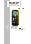
Calibrateur de sondes RTD RTD probes temperature calibrator Temperaturkalibrator für RTD sonden Calibratore de temperatura sonda RTD Calibrador de temperatura sonda RTD C.A 1623 FR AN Ç AI S ENGLISH DEUTCH IT AL I ANO ESPAÑOL Notice de fonctionnement User’s manual Bedienungsanleitung Libretto d’Istruzioni Manual de instrucciones Calibrateur de température sonde RTD C.A 1623 Français SOMMAIRE 1 INTRODUCTION .......................................................................................... 4 2 PRÉSENTATION DE LA FACE AVANT .................................................. 5 3 INSTRUCTIONS D’UTILISATION ............................................................ 6 3.1 3.2 MESURE SONDE RTD :.......................................................................... 6 SIMULATION RTD : ............................................................................... 6 4 SPECIFICATIONS ........................................................................................ 7 5 SPÉCIFICATIONS GÉNÉRALES .............................................................. 8 6 ADAPTATEUR SECTEUR (ACCESSOIRE) ............................................. 8 6.1 6.2 7 BRANCHEMENT DE L’ADAPTATEUR SECTEUR ............................. 8 CARACTÉRISTIQUES AC/DC DE L’ADAPTATEUR SECTEUR ....... 9 MAINTENANCE ........................................................................................... 9 7.1 7.2 7.3 7.4 7.5 NETTOYAGE........................................................................................... 9 CALIBRATION ...................................................................................... 10 REMPLACEMENT DES PILES............................................................. 10 VÉRIFICATION MÉTROLOGIQUE .................................................... 10 RÉPARATION ....................................................................................... 10 8 GARANTIE .................................................................................................. 11 9 POUR COMMANDER ................................................................................ 11 2 Français Calibrateur de température sonde RTD C.A 1623 Vous venez d’acquérir un calibrateur de température sonde C.A 1623 et nous vous remercions de votre confiance. Pour obtenir le meilleur service de votre appareil : • lisez attentivement cette notice de fonctionnement, • respectez les précautions d’emploi SIGNIFICATION DES SYMBOLES UTILISÉS Tri sélectif des déchets pour le recyclage des matériels électriques et électroniques au sein de l'Union Européenne. Conformément à la directive WEEE 2002/96/EC : ce matériel ne doit pas être traité comme déchet ménager. ATTENTION, risque de DANGER ! Consulter la notice de fonctionnement. Dans la présente notice de fonctionnement, les instructions précédées de ce symbole, si elles ne sont pas bien respectées ou réalisées, peuvent occasionner un accident corporel ou endommager l’appareil et les installations. Conforme aux directives de l’Union Européenne. Borne de terre. Appareil entièrement protégé par isolation double ou isolation renforcée. Batterie 3 Calibrateur de température sonde RTD C.A 1623 Français PRÉCAUTIONS D’EMPLOI Afin d’éviter tout risque d’électrocution ou de blessures corporelles : • • • • • N’appliquez jamais de tension supérieure à 30V entre deux bornes, ou entre une borne et la terre, Assurez-vous que le couvercle des piles est fermé et verrouillé avant d’utiliser le calibrateur, Débranchez les fils d’essais du calibrateur avant d’ouvrir le couvercle des piles, N’utilisez pas le calibrateur ou ses cordons s’ils paraissent endommagés, N’utilisez pas le calibrateur en présence de gaz explosif, de vapeur ou de poussière, Afin d’éviter d’endommager le calibrateur : • • Veuillez choisir la bonne borne et nombre de fils avant d’utiliser le calibrateur pour effectuer des mesures ou une calibration, Retirez le calibrateur de son environnement d’utilisation après l’avoir éteint. 1 INTRODUCTION Le calibrateur de température RTD est un instrument de mesure de précision doublé d’un générateur. Il permet de calibrer les sondes RTD (sonde platine). Le C.A 1623 peut mesurer ou simuler 7 types de sondes différentes (°C ou °F), ainsi que la résistance. Il ne peut toutefois pas être utilisé comme instrument de mesure et générateur à la fois. 4 Français Calibrateur de température sonde RTD C.A 1623 2 PRÉSENTATION DE LA FACE AVANT Le panneau avant est tel qu’il apparaît sur l’image ci-dessous : 1. 2. 3. 4. 5. 6. 7. 8. 9. 10. 11. 12. 13. 14. 15. 16. 17. 18. Borne d’entrée 4 fils Borne d’entrée / sortie 2 fils Borne d’entrée / sortie 2 fils Borne d’entrée 3 fils Touche de mise sous tension Touche de sélection de type de sonde RTD Touche °C / °F Touche entrée / sortie Touche d’augmentation de la valeur supérieure / sélection nombre fil Touche de diminution de la valeur supérieure / sélection nombre fil Touche d’augmentation de la valeur inférieure Touche de diminution de la valeur inférieure Indicateur de batterie faible Indicateur de l’état d’entrée Indicateur de l’état de sortie Valeur relevée Indicateur d’unité Indicateur de type de sonde k 5 Calibrateur de température sonde RTD C.A 1623 Français 3 INSTRUCTIONS D’UTILISATION 3.1 1. 2. 3. 4. 5. 6. 3.2 1. 2. 3. 4. 5. 6. 7. MESURE SONDE RTD : Appuyez sur la touche 5 pour mettre le calibrateur sous tension. Appuyez sur la touche 8 pour être en mode entrée. Appuyez sur la touche de type de sonde RTD pour sélectionner le type de mesure souhaitée. Branchez la RTD ou Résistance sur la borne d’entrée. Si vous voulez mesurer en mode 3 fils / 4 fils, appuyez sur la touche de sélection de nombre de fil 9, 10, puis branchez le fil sur la borne d’entrée correspondant. Relevez la valeur 16. SIMULATION RTD : Appuyez sur la touche 5 pour mettre le calibrateur sous tension. Appuyez sur la touche 8 pour être en mode sortie. Appuyez sur la touche 6 pour sélectionner le type de mesure souhaité. Appuyez sur les touches 9, 10, 11 et 12 pour définir la valeur voulue. Branchez la sonde RTD ou l’ohmmètre sur la borne d’entrée. Si vous voulez une sortie en mode 3 fils / 4 fils, branchez l’autre fil sur le jack 2 fils comme sur l’image. Si vous souhaitez modifier la valeur de sortie ou type de RTD, utilisez la touche de mode RTD 6, appuyez sur les touches 9, 10, 11 ou 12. 6 Français Calibrateur de température sonde RTD C.A 1623 4 SPECIFICATIONS Toutes les spécifications sont garanties un an après calibration, pour une température comprise entre 18°C et 28°C et en alimenté par des piles. Caractéristiques pour la mesure (entrée) / simulation (sortie) de résistance : PLAGE Précision de mesure 4 fils ± Ω 0.00Ω ~400.00Ω 0,1 400.0Ω ~ 1500.0Ω 0,5 Précision de simulation ±Ω Excitation admissible mA 0,15 0.1 ~ 0.5 0,1 0.5 ~ 3.0 0,5 0.05 ~ 0.8 1 0.05 ~ 0.4 1 1500.0Ω ~ 3200.0Ω 2 Les valeurs du courant d’excitation admissible ne sont applicables qu’en mode simulation. Caractéristiques pour la mesure (entrée) / simulation (sortie) de sonde RTD : Précision en °C Mode Pt10 385 Pt50 385 Pt100 385 Pt200 385 Pt500 385 Pt1000 385 Pt100 JIS Plage -200~800°C / -328~1472°F -200~800°C / -328~1472°F -200~800°C / -328 ~ 1472°F -200~250°C / -328~482°F 250~630°C / 482~1166°F -200~500°C / -328~932°F 500~630°C / 932~1166°F -200~100°C / -328~212°F 100~630°C / 212~1166°F 200~630°C / 328~1166°F Entrée 4 fils Entrée 2 fils / 3 fils Sortie Excitation admissible mA 0,1 ~ 3,0 0,7 1,0 0,7 0,1 ~ 3,0 0,33 0,5 0,33 0,1 ~ 3,0 0,2 0,3 0,2 0,8 1,6 0,8 0,3 0,6 0,3 0,4 0,9 0,4 0,2 0,4 0,2 0,2 0,5 0,2 0,2 0,5 0,3 0,1 ~ 3,0 0,05 ~ 3,0 0,1 ~ 3,0 0,1 ~ 3,0 Le courant d’excitation admissible n’est applicable qu’en mode simulation. 7 Calibrateur de température sonde RTD C.A 1623 Français 5 SPÉCIFICATIONS GÉNÉRALES Tension maxi. appliquée entre une borne et la terre ou entre deux bornes : 30V Résolution : RTD 0,1°C / °F - Résistance 0,01 / 0,1Ω Température de stockage : - 40°C ~ 60°C Température de service : - 10°C ~ 55°C Altitude de service : 3000 mètres maxi. Coefficient de température : ± 0,01% / °C sur 0°C ~ 18°C et 28°C ~ 50°C Humidité relative : 95% jusqu’à 30°C, 75% jusqu’à 40°C, 45% jusqu’à 50°C, 35% jusqu’à 55°C Choc : aléatoire 2g, 5Hz à 500Hz Alimentation : 6 piles AAA 1,5V Dimensions : 205mm × 98mm × 46mm Masse : 472g (piles comprises) 6 ADAPTATEUR SECTEUR (ACCESSOIRE) 6.1 1. 2. 3. BRANCHEMENT DE L’ADAPTATEUR SECTEUR Raccordez le cordon secteur à l’adaptateur. Branchez le cordon AC sur la prise secteur (100 V – 240 V). Branchez la fiche d’alimentation DC de l’adaptateur à la prise DC de l’instrument de mesure. Prise DC Fiche DC Cordon secteur Adaptateur secteur. 8 Français 6.2 Calibrateur de température sonde RTD C.A 1623 CARACTÉRISTIQUES AC/DC DE L’ADAPTATEUR SECTEUR Entrée : 100 V – 240 VAC, 50 – 60 Hz 1,8 A 2 A MAX Sortie : 12 VDC Polarité : ATTENTION : 1. Utilisez l’adaptateur secteur d’origine. D’autres modèles risqueraient d’endommager votre instrument ; 2. L’adaptateur est prévu pour un usage en intérieur uniquement. 3. Connectez en premier la fiche du cordon AC à la prise secteur et ensuite insérez fermement la fiche d’alimentation dans la prise DC de l’appareil de mesure. Pour le débrancher, retirez bien perpendiculairement la fiche DC et ensuite débranchez l’adaptateur de la prise secteur. 4. N’utilisez pas l’adaptateur secteur sur un autre équipement que cet appareil. 5. En fonctionnement, il est normal que l’adaptateur secteur chauffe. 6. Ne démontez pas l’adaptateur secteur. Ce serait dangereux. 7. N’utilisez pas l’adaptateur dans un local surchauffé ou humide. 8. Evitez de soumettre l’adaptateur secteur à des chocs violents. 9. Il est normal que l’adaptateur secteur émette un bruit lorsqu’il fonctionne. 7 MAINTENANCE Pour la maintenance, utilisez seulement les pièces de rechange qui ont été spécifiées. Le fabricant ne pourra être tenu responsable de tout accident survenu suite à une réparation effectuée en dehors de son service après-vente ou des réparateurs agréés. 7.1 • • • NETTOYAGE Déconnectez tout branchement du calibrateur. Nettoyez régulièrement le boîtier avec un chiffon humide et du détergent. N’utilisez pas de produits abrasifs ou de solvants. 9 Calibrateur de température sonde RTD C.A 1623 7.2 • 7.3 Français CALIBRATION Calibrez votre calibrateur une fois par an pour vous assurer d’un fonctionnement conforme aux spécifications. REMPLACEMENT DES PILES • Changez les piles lorsque l’écran LCD indique • Pour changer les piles, mettez le calibrateur hors tension, retirez la vis du couvercle des piles et remplacez les piles par des piles AAA 1,5V neuves. 7.4 VÉRIFICATION MÉTROLOGIQUE Comme tous les appareils de mesure ou d’essais, une vérification périodique est nécessaire. Nous vous conseillons une vérification annuelle de cet appareil. Pour les vérifications et étalonnages, adressez-vous à nos laboratoires de métrologie accrédités COFRAC ou aux centres techniques MANUMESURE. Renseignements et coordonnées sur demande : Tél. : 02 31 64 51 55 - Fax : 02 31 64 51 72 7.5 RÉPARATION Pour les réparations sous garantie et hors garantie, contactez votre agence commerciale Chauvin Arnoux la plus proche ou votre centre technique régional Manumesure qui établira un dossier de retour et vous communiquera la procédure à suivre. Coordonnées disponibles sur notre site : http://www.chauvin-arnoux.com/ ou par téléphone aux numéros suivants : 02 31 64 51 55 (centre technique Manumesure), 01 44 85 44 85 (Chauvin Arnoux). Pour les réparations hors de France métropolitaine, sous garantie et hors garantie, retournez l’appareil à votre agence Chauvin Arnoux locale ou à votre distributeur. 10 Français Calibrateur de température sonde RTD C.A 1623 8 GARANTIE Notre garantie s’exerce, sauf stipulation expresse, pendant douze mois après la date de mise à disposition du matériel. Extrait de nos Conditions Générales de Vente, communiquées sur demande. La garantie ne s’applique pas suite à : une utilisation inappropriée de l’équipement ou à une utilisation avec un matériel incompatible, des modifications apportées à l’équipement sans l’autorisation explicite du service technique du fabricant, des travaux effectués sur l’appareil par une personne non agréée par le fabricant, une adaptation à une application particulière, non prévue par la définition du matériel ou non indiquée dans la notice de fonctionnement, des dommages dus à des chocs, chutes ou inondations. 9 POUR COMMANDER C.A 1623 ........................................................................................... P01654623 Fourni avec un étui, 1 paire de cordons de test, 1 paire de pinces crocodile, 6 piles AAA 1,5 V et 1 notice de fonctionnement 5 langues. Accessoires & rechanges Alimentation secteur calibrateurs C.A 1621, C.A 1623, C.A 1631 .... P01103057 11 C.A 1621 Thermocouple temperature calibrator English CONTENTS 1 INTRODUCTION ........................................................................................ 14 2 DESCRIPTION OF THE FRONT PANEL ............................................... 15 3 OPERATING INSTRUCTIONS ................................................................ 16 3.1 3.2 RTD PROBE MEASUREMENT: ........................................................... 16 RTD SIMULATION : ............................................................................. 16 4 SPECIFICATIONS ...................................................................................... 17 5 GENERAL SPECIFICATIONS ................................................................. 18 6 POWER SUPPLY (ADAPTER) ................................................................. 19 6.1 6.2 7 CONNECTING THE POWER ADAPTER ............................................ 19 AC/DC ADAPTER INFORMATION ..................................................... 19 MAINTENANCE ......................................................................................... 20 7.1 7.2 7.3 7.4 7.5 CLEANING ............................................................................................ 20 CALIBRATION ...................................................................................... 20 REPLACING THE BATTERIES............................................................ 20 METROLOGICAL CHECK ................................................................... 20 REPAIR .................................................................................................. 20 8 WARRANTY ................................................................................................ 21 9 TO ORDER ................................................................................................... 21 12 English C.A 1623 RTD probe temperature calibrator You have just purchased a C.A 1623 RTD probe temperature calibrator and we thank you for your confidence. For best results from your device: • read this user manual attentively, • observe the precautions for its use. MEANINGS OF THE SYMBOLS USED Selective sorting of wastes for the recycling of electrical and electronic equipment within the European Union. In conformity with directive WEEE 2002/96/EC: this equipment must not be treated as household waste. WARNING, risk of DANGER! Refer to the operating data sheet. In this operating data sheet, failure to correctly execute or perform the instructions preceded by this symbol may cause bodily injury or damage the device and the installations. Complies with European Union directives. Earth. Device entirely protected by double insulation or reinforced insulation. Battery 13 C.A 1623 RTD probe temperature calibrator English PRECAUTIONS FOR USE To avoid all risk of electrocution or bodily injury: • • • • • Never apply a voltage in excess of 30 V between two terminals, or between a terminal and ground, Make sure that the cover of the battery compartment is closed and locked before using the calibrator, Disconnect the test leads from the calibrator before opening the cover of the battery compartment, Do not use the calibrator if it is damaged, Do not use the calibrator in the presence of explosive gases, vapour/steam, or dust. In order to avoid damaging the calibrator: • • Choose the right connection and number of wires before using the calibrator to make measurements or a calibration, Remove the calibrator from its working environment when it is off. 1 INTRODUCTION The RTD temperature calibrator is a precision portable measuring instrument combined with a generator. It can be used to calibrate RTD probes (platinium resistance thermometers). The C.A 1623 can measure or simulate 7 different types of probe (°C or °F), and resistance. It cannot be used as a measuring instrument and as a generator at the same time. 14 English C.A 1623 RTD probe temperature calibrator 2 DESCRIPTION OF THE FRONT PANEL The front panel looks like this : 1. 2. 3. 4. 5. 6. 7. 8. 9. 10. 11. 12. 13. 14. 15. 16. 17. 18. 4-wire input terminal 2-wire input / output terminal 2-wire input / output terminal 3-wire input terminal Power On key Key for selection of type of RTD probe °C / °F key Input / output key Key to increase upper value / selection of number of wires Key to decrease upper value / selection of number of wires Key to increase lower value Key to decrease lower value Battery Low indicator Input status indicator Output status indicator Measured value Unit indicator Indicator of type of probe 15 k C.A 1623 RTD probe temperature calibrator English 3 OPERATING INSTRUCTIONS 3.1 1. 2. 3. 4. 5. 6. 3.2 1. 2. 3. 4. 5. 6. 7. RTD PROBE MEASUREMENT: Press key 5 to power up the calibrator. Press key 8 to be in input mode. Press the Type of RTD probe key to select the desired type of measurement. Connect the RTD or Resistor to the input terminal. If you want to measure in 3-wire / 4-wire mode, press the Select number of wires key (9, 10), then connect the wire to the corresponding input terminal. Read the value on the display (16). RTD SIMULATION : Press key 5 to power up the calibrator. Press key 8 to be in output mode. Press key 6 to select the desired type of measurement. Press keys 9, 10, 11 and 12 to define the desired value. Connect the RTD probe or the ohmmeter to the input terminal. If you want an output in 3-wire/4-wire mode, connect the other wire to the 2-wire jack as shown in the image to the left; If you want to change the output value or type of RTD, use RTD mode key 6 and press key 9, 10, 11, or 12. 16 English C.A 1623 RTD probe temperature calibrator 4 SPECIFICATIONS All of the specifications are guaranteed for one year after calibration, at temperatures between 18°C and 28°C, with battery power. Characteristics for the resistance measurement (input)/simulation (output): RANGE Accuracy of 4-wire measurement ± Ω 0.00 Ω ~400.00 Ω 0.1 400.0 Ω ~ 1500.0 Ω 0.5 1 1500.0 Ω ~ 3200.0 Ω 2 Accuracy of simulation ± Ω Acceptable excitation in mA 0.15 0.1 ~ 0.5 0.1 0.5 ~ 3.0 0.5 0.05 ~ 0.8 1 0.05 ~ 0.4 The acceptable excitation current values apply only in simulation mode. Characteristics for the RTD probe measurement (input)/simulation (output): Accuracy in °C Mode Pt10 385 Pt50 385 Pt100 385 Pt200 385 Pt500 385 Pt1000 385 Pt100 JIS Range -200~800°C / -328~1472°F -200~800°C / -328~1472°F -200~800°C / -328 ~ 1472°F -200~250°C / -328~482°F 250~630°C / 482~1166°F -200~500°C / -328~932°F 500~630°C / 932~1166°F -200~100°C / -328~212°F 100~630°C / 212~1166°F 200~630°C / 328~1166°F 4-wire input 2-wire / 3-wire input Output Acceptable excitation mA 0.1 ~ 3.0 0.7 1.0 0.7 0.1 ~ 3.0 0.33 0.5 0.33 0.1 ~ 3.0 0.2 0.3 0.2 0.8 1.6 0.8 0.3 0.6 0.3 0.4 0.9 0.4 0.2 0.4 0.2 0.2 0.5 0.2 0.2 0.5 0.3 0.1 ~ 3.0 0.05 ~ 3.0 0.1 ~ 3.0 The acceptable excitation current applies only in simulation mode. 17 0.1 ~ 3.0 C.A 1623 RTD probe temperature calibrator English 5 GENERAL SPECIFICATIONS Max. voltage applied between a terminal and ground or between two terminals: 30V Resolution: RTD 0.1°C/°F - Resistance 0.01 / 0.1 Ω Storage temperature: - 40°C ~ 60°C Service temperature: - 10°C ~ 55°C Service altitude: 3000 metres max. Temperature coefficient: ±0.01%/°C on 0°C ~18°C and 28°C ~50°C Relative humidity: 95% up to 30°C, 75% up to 40°C, 45% up to 50°C, 35% up to 55°C Shock: random, 2 g, 5 Hz to 500 Hz Alimentation: 6 1.5 V AAA batteries Dimensions: 205 mm × 98 mm × 46 mm Mass: 472 g (with batteries) 18 English C.A 1623 RTD probe temperature calibrator 6 POWER SUPPLY (ADAPTER) 6.1 1. 2. 3. CONNECTING THE POWER ADAPTER Connect the AC power cord to the AC-DC converter. Plug the AC power cord into an electrical outlet (100 V-240 V). Plug the DC power plug of the converter into DC power socket of the meter. DC power socket DC power plug AC power cord AC-DC converter. 6.2 AC/DC ADAPTER INFORMATION Input: 100 V-240 V AC, 50-60 Hz 1.8 A 2 A MAX Output: DC 12 V Polarity: WARNING: 1. Please use the original AC power adapter, using other AC power adapter may damage your instrument. 2. The AC power adapter can only be used indoors. 3. Please plug the AC power cord into an electrical outlet first and then firmly insert DC plug into DC input end in the right of the meter. When unplugged, firstly pull out the DC plug perpendicular to DC input end and then unplug the AC plug from the electrical outlet. 4. Do not use the AC power adapter in other equipment except this instrument. 5. In use, it is a normal phenomenon that the AC power adapter will be hot. 6. Do not demolish the AC power adapter. Otherwise, it may be dangerous. 7. Do not use the AC power adapter in a high temperature or wet place. 8. Please make the AC power adapter avoid a strong bump. 9. It is normal when the AC power adapter make some noise in use. 19 C.A 1623 RTD probe temperature calibrator English 7 MAINTENANCE For maintenance, use only the specified spare parts. The manufacturer cannot be held liable for an accident that occurs following a repair not done by its customer service department or an approved repairer. 7.1 • • • 7.2 • 7.3 • • 7.4 CLEANING Disconnect all connections to the calibrator. Clean the housing regularly with a wet cloth and detergent. Do not use abrasive products or solvents. CALIBRATION Calibrate your calibrator once a year to make sure that it operates in conformity with the specifications. REPLACING THE BATTERIES Replace the batteries when the LCD screen indicates To replace the batteries, switch the calibrator off, withdraw the screw holding the cover on the battery compartment, and replace the batteries with new 1.5 V AAA batteries. METROLOGICAL CHECK Like all measuring and testing devices, the calibrator must be checked periodically. This instrument should be checked at least once a year. For checks and calibrations, contact one of our accredited metrology laboratories (information and contact details available on request), at our Chauvin-Arnoux subsidiary or the branch in your country. 7.5 REPAIR For all repairs before or after expiry of warranty, please return the device to your distributor. 20 English C.A 1623 RTD probe temperature calibrator 8 WARRANTY Our warranty applies, except as otherwise expressly stipulated, for twelve months counting from the date of availability of the equipment. Extract from our General Terms of Sale, communicated on request. The warranty is void following: Inappropriate use of the equipment or use with an incompatible device, Modifications made to the equipment without the explicit approval of the manufacturer's technical staff, Work done on the device by a person not approved by the manufacturer, Adaptation to a particular application not anticipated in the definition of the equipment or indicated in the operating data sheet, Damage due to an impact, fall, or flooding. 9 TO ORDER C.A 1623 ........................................................................................... P01654623 Supplied with 1 case, 1 pair of test leads, 2 alligator clips, 6 1.5 V AAA batteries, and 1 set of operating instructions in 5 languages. Accessories & spares Mains power unit C.A 1621, C.A 1623, C.A 1631 ............................. P01103057 21 Temperaturkalibrator für Thermoelement C.A 1623 Deutsch INHALTSÜBERSICHT 1 EINFÜHRUNG............................................................................................. 24 2 PRÄSENTATION DER VORDERSEITE ................................................. 25 3 GEBRAUCHSANLEITUNG....................................................................... 26 3.1 3.2 MESSEN / EINGANG THERMOELEMENT ODER MILLIVOLT: ..... 26 SIMULATION RTD : ............................................................................. 26 4 SPEZIFIKATIONEN ................................................................................... 27 5 ALLGEMEINE SPEZIFIKATIONEN ...................................................... 28 6 NETZADAPTER (ZUBEHÖR) .................................................................. 29 6.1 6.2 7 NETZADAPTERANSCHLUSS ............................................................. 29 AC/DC APDAPTER INFORMATION................................................... 29 WARTUNG UND PFLEGE DES GERÄTS .............................................. 30 7.1 7.2 7.3 7.4 7.5 REINIGUNG........................................................................................... 30 KALIBRIEREN ...................................................................................... 30 BATTERIEWECHSEL ........................................................................... 30 EICHUNG ............................................................................................... 30 REPARATUR ......................................................................................... 30 8 GARANTIE .................................................................................................. 31 9 BESTELLANGABEN, LIEFERUMFANG ............................................... 31 22 Deutsch Temperaturkalibrator für Thermoelement C.A 1623 Sie haben einen Temperaturkalibrator für RTD Sonden C.A 1623 erstanden, wir danken Ihnen für Ihr Vertrauen. Für die Erlangung eines optimalen Betriebsverhaltens Ihres Gerätes: • Lesen Sie bitte diese Betriebsanleitung aufmerksam durch und • Beachten Sie bitte die Anwendungshinweise BEDEUTUNG DER SYMBOLE Weist darauf hin, dass dieses Gerät in der EU gemäß der EC-Richtlinie für Elektro- und Elektronikschrott WEEE 2002/96/EC entsorgt und recycelt werden muss. ACHTUNG, GEFAHRENRISIKO! Lesen Sie die Bedienungsanleitung, bevor Sie das Gerät benutzen.Werden die Anweisungen in dieser Bedienungsanleitung, denen dieses Symbol vorangestellt ist, nicht beachtet oder eingehalten, kann es zu Verletzungen von Menschen oder Beschädigungen des Geräts oder der Installationen kommen. Erfüllt die EU-Richtlinien. Erdungsklemme. Das Gerät ist schutzisoliert bzw. durch eine verstärkte Isolierung geschützt. Batterie 23 Temperaturkalibrator für Thermoelement C.A 1623 Deutsch BEDIENUNGSHINWEISE Vermeiden von Stromschlag bzw. Körperverletzungen : • • • • • Zwischen zwei Buchsen bzw. zwischen Buchse und Erde darf keine Spannung über 30 V angelegt werden, Vor Gebrauch muss sichergestellt werden, dass der Batteriefachdeckel geschlossen und verriegelt ist, Vor dem Öffnen des Batteriefachdeckels müssen die Prüfdrähte vom Kalibrator abgenommen werden, Niemals einen beschädigten Kalibrator benutzen, Den Kalibrator nicht in Bereichen mit explosionsfähigen Gasen, Dampf oder viel Staub verwenden. Vermeiden von Geräteschäden am Kalibrator : • • Vor Gebrauch die korrekte Drahtanzahl und Buchse zum Messen bzw. Kalibrieren auswählen. Den abgeschalteten Kalibrator aus dem Einsatzgebiet entfernen. 1 EINFÜHRUNG Der Thermokalibrator für RTD-Sonden ist ein Präzisionsmessgerät mit Generator. Er dient zum Kalibrieren von RTD-Sonden (pt-Sonde). C.A 1623 misst bzw. simuliert 7 verschiedene Sonden-Typen (°C oder °F) sowie den Widerstand. Allerdings kann er nicht gleichzeitig als Messgerät und als Generator verwendet werden. 24 Deutsch Temperaturkalibrator für Thermoelement C.A 1623 2 PRÄSENTATION DER VORDERSEITE Die Vorderseite sieht wie hier abgebildet aus: 1. 2. 3. 4. 5. 6. 7. 8. 9. 10. 11. 12. 13. 14. 15. 16. 17. 18. Eingangsbuchse 4 Leiter Eingangs- / Ausgangsbuchse 2 Leiter Eingangs- / Ausgangsbuchse 2 Leiter Eingangsbuchse 3 Leiter Einschalttaste Auswahltaste für RTD-Sonde Taste °C / °F Taste Eingang / Ausgang Steigern des höchsten Werts / Auswahl Drahtanzahl Senken des höchsten Werts / Auswahl Drahtanzahl Steigern des niedrigsten Werts Senken des niedrigsten Werts Anzeige bei geringem Akkuladestand Anzeige des Eingangsstatus Anzeige des Ausgangsstatus Abgelesener Wert Einheitsangabe Anzeige des Sondentyps 25 k Temperaturkalibrator für Thermoelement C.A 1623 Deutsch 3 GEBRAUCHSANLEITUNG 3.1 1. 2. 3. 4. 5. 6. 3.2 1. 2. 3. 4. 5. 6. 7. MESSEN / EINGANG THERMOELEMENT ODER MILLIVOLT: Mit der Taste 5 den Kalibrator unter Spannung setzen. Im Eingangsmodus auf die Taste 8 drücken. Auswahl der gewünschten Messart mit der Taste RTD-Sonde. RTD oder Widerstand am Eingang anschließen. Wenn Sie im Modus 3 Leiter / 4 Leiter messen möchten, drücken Sie die Wahltaste für die Drahtanzahl 9, 10 und schließen dann die entsprechende Drahtanzahl am Eingang an. Wert 16 ablesen. SIMULATION RTD : Mit der Taste 5 den Kalibrator unter Spannung setzen. Im Ausgangsmodus auf die Taste 8 drücken. Mit der Taste 6 die gewünschte Messart auswählen. Mit den Tasten 9, 10, 11 und 12 den gewünschten Wert definieren. RTD-Sonde oder Ohmmeter am Eingang anschließen. Wenn Sie einen Ausgang im Modus 3 Leiter / 4 Leiter wünschen, schließen Sie den anderen Draht an den 2-Leiter-Stecker wie links abgebildet an. Ändern des Ausgangswerts oder der RTDType mit der RTD-Modus-Taste 6, mit den Tasten 9, 10, 11 und 12. 26 Deutsch Temperaturkalibrator für Thermoelement C.A 1623 4 SPEZIFIKATIONEN Alle Spezifikationen werden bei Temperaturen von 18 bis 28°C und bei Batterieversorgung für ein Jahr nach dem Kalibrieren gewährleistet. Eigenschaften bei Messen (Eingang) / Simulation (Ausgang) Widerstand: BEREICH Messgenauigkeit 4 Leiter ± Ω 0.00 Ω ~400.00 Ω 0,1 400.0 Ω ~ 1500.0 Ω 0,5 Simulationsgenauigkeit ±Ω Zul. Erregung mA 0,15 0.1 ~ 0.5 0,1 0.5 ~ 3.0 0,5 0.05 ~ 0.8 1 0.05 ~ 0.4 1 1500.0 Ω ~ 3200.0 Ω 2 Die zulässigen Erregerstromwerte gelten nur für den Simulationsmodus. Eigenschaften bei Messen (Eingang) / Simulation (Ausgang) RTD-Sonde: Genauigkeit °C Modus Pt10 385 Pt50 385 Pt100 385 Pt200 385 Pt500 385 Pt1000 385 Pt100 JIS BEREICH -200~800°C / -328~1472°F -200~800°C / -328~1472°F -200~800°C / -328 ~ 1472°F -200~250°C / -328~482°F 250~630°C / 482~1166°F -200~500°C / -328~932°F 500~630°C / 932~1166°F -200~100°C / -328~212°F 100~630°C / 212~1166°F 200~630°C / 328~1166°F Eingang 4 Leiter Eingang 2 Leiter / 3 Leiter Ausgang Zul. Erregung mA 0,1 ~ 3,0 0,7 1,0 0,7 0,1 ~ 3,0 0,33 0,5 0,33 0,1 ~ 3,0 0,2 0,3 0,2 0,8 1,6 0,8 0,3 0,6 0,3 0,4 0,9 0,4 0,2 0,4 0,2 0,2 0,5 0,2 0,2 0,5 0,3 0,1 ~ 3,0 0,05 ~ 3,0 0,1 ~ 3,0 Der zulässige Erregerstromwert gilt nur für den Simulationsmodus. 27 0,1 ~ 3,0 Temperaturkalibrator für Thermoelement C.A 1623 Deutsch 5 ALLGEMEINE SPEZIFIKATIONEN Maximale Spannung zwischen Buchse und Erde bzw. zwischen zwei Buchsen: 30V Auflösung: RTD 0,1°C / °F - Widerstand 0,01 / 0,1 Ω Lagertemperatur: - 40°C ~ 60°C Betriebstemperatur: - 10°C ~ 55°C Betriebshöhe: max. 3000 m Temperaturkoeffizient: ± 0,01% / °C bei 0°C ~18°C und 28°C ~50°C Relative Feuchte: bis 55°C 95% bis 30°C, 75% bis 40°C, 45% bis 50°C, 35% Schlag: aleatorisch 2 g, 5 Hz bis 500 Hz Stromversorgung: 6 Batterien AAA 1,5 V Abmessungen: 205 mm × 98 mm × 46 mm Gewicht: 472 g (mit Batterien) 28 Deutsch Temperaturkalibrator für Thermoelement C.A 1623 6 NETZADAPTER (ZUBEHÖR) 6.1 1. 2. 3. NETZADAPTERANSCHLUSS Das Netzkabel an den Adapter anschließen. Das AC-Kabel an die Netzsteckdose anschließen (100V-240V). Den DC-Stecker des Adapters an die DC-Buchse des Messgeräts anschließen. DC power socket DC-Buchse DC power plug DC-Stecker AC power cord AC-DC converter. Netzadapter 6.2 Netzkabel AC/DC APDAPTER INFORMATION EINGANG : 100V-240VAC, 50-60Hz 1,8A 2A MAX AUSGANG : DC 12V Polarität : ACHTUNG : 1. Verwenden Sie nur den Original-Netzadapter. Andere Modelle könnten das Gerät beschädigen! 2. Der Adapter ist nur für den Gebrauch in Innenräumen geeignet. 3. Schließen sie zuerst den Stecker des AC-Kabels an die Netzsteckdose an, dann schieben Sie fest den Versorgungsstecker in die DC-Buchse des Messgeräts hinein. Zum Abstecken ziehen Sie zuerst den DC-Stecker lotrecht aus dem Gerät und dann nehmen Sie den Adapter von der Netzsteckdose ab. 4. Verwenden Sie den Netzadapter nicht für andere Geräte! 5. Es ist ganz normal, dass der Netzadapter beim Betrieb warm wird. 6. Nehmen Sie den Netzadapter nicht auseinander, das wäre gefährlich. 7. Verwenden Sie den Adapter nicht in einem überheizten oder feuchten Raum. 8. Setzen Sie den Netzadapter keinen heftigen Stößen aus. 9. Es ist ganz normal, dass der Netzadapter beim Betrieb Geräusche entwickelt. 29 Temperaturkalibrator für Thermoelement C.A 1623 Deutsch 7 WARTUNG UND PFLEGE DES GERÄTS Benutzen Sie für die Wartung ausschließlich die angegebenen Ersatzteile. Der Hersteller kann nicht für Unfälle haftbar gemacht werden, die auf eine Reparatur zurückzuführen sind, die nicht von seinem Kundendienst oder einem zugelassenen Reparaturservice durchgeführt wurde. 7.1 • • • 7.2 • 7.3 • • 7.4 REINIGUNG Alle Anschlüsse vom Kalibrator abnehmen. Das Gehäuse regelmäßig mit einem feuchten Tuch und Reinigungsmittel säubern. Keine schleifenden Produkte oder Lösungsmittel verwenden. KALIBRIEREN Für einwandfreien, spezifikationsgemäßen Betrieb muss der Kalibrator ein Mal pro Jahr kalibriert werden. BATTERIEWECHSEL Wenn der LCD-Bildschirm anzeigt, wechseln Sie die Batterien. Zum Batteriewechsel den Kalibrator außer Spannung setzen, die Schraube vom Batteriefachdeckel entfernen und die gebrauchten Batterien mit neuen AAA 1,5 V Batterien auswechseln. EICHUNG Wie auch bei anderen Mess- oder Prüfgeräten ist eine regelmäßige Geräteüberprüfung erforderlich. Wir empfehlen eine jährliche Überprüfung dieses Geräts. Wenden Sie sich zur Überprüfung und Eichung an unsere zugelassenen Messlabors, an die Filiale von Chauvin-Arnoux oder Ihre zuständige Landesvertretung. Auskünfte und Adressen stehen auf Anfrage hin zur Verfügung: Tel.: +332 31 64 51 43 Fax: +332 31 64 51 09 7.5 REPARATUR Senden Sie das Gerät bei Reparaturen innerhalb und außerhalb der Garantie an Ihren Händler zurück. 30 Deutsch Temperaturkalibrator für Thermoelement C.A 1623 8 GARANTIE Außer ausdrücklich anders lautenden Angaben beträgt die Garantiefrist für unsere Geräte zwölf Monate nach Bereitstellung des Geräts beim Kunden. Auszug aus unseren allgemeinen Verkaufsbedingungen, die wir Ihnen auf Anfrage gerne zusenden. Die Garantie verfällt bei: - unsachgemäße Benutzung des Gerätes oder Verwendung mit inkompatiblen anderen Geräten; - Veränderung des Geräts ohne die ausdrückliche Genehmigung der technischen Abteilung des Herstellers; - Eingriffe in das Gerät durch eine nicht vom Hersteller dazu befugte Person; - Anpassung des Geräts an nicht vorgesehene und nicht in der Anleitung aufgeführte Verwendungszwecke; - Schäden durch Stöße, Herunterfallen, Überschwemmung. 9 BESTELLANGABEN, LIEFERUMFANG C.A 1623 ........................................................................................... P01654623 Der Lieferumfang umfasst 1 Transporttasche, 1 Satz Messleitungen, 2 Krokodilklemmen, 6 Batterien AAA 1,5 V und 1 fϋnfsprachige Bedienungsanleitung. Zubehör & Ersatzteile. Netzanschluss C.A 1621, C.A 1623, C.A 1631 ................................. P01103057 31 Italiano Calibratore di temperatura termocoppia C.A 1621 INDICE 1 INTRODUZIONE ........................................................................................ 34 2 PRESENTAZIONE DEL LATO ANTERIORE ....................................... 35 3 ISTRUZIONI D’UTILIZZO ....................................................................... 36 3.1 3.2 MISURA SONDA RTD: ......................................................................... 36 SIMULAZIONE RTD:............................................................................ 36 4 SPECIFICHE ............................................................................................... 37 5 SPECIFICHE GENERALI ......................................................................... 38 6 ADATTATORE RETE (ACCESSORIO) .................................................. 39 6.1 6.2 7 ALLACCIAMENTO DELL’ADATTATORE RETE ............................. 39 CARATTERISTICHE AC/DC DELL’ADATTATORE RETE .............. 39 MANUTENZIONE ...................................................................................... 40 7.1 7.2 7.3 7.4 7.5 PULIZIA ................................................................................................. 40 CALIBRAZIONE ................................................................................... 40 SOSTITUZIONE DELLE PILE .............................................................. 40 VERIFICA METROLOGICA................................................................. 40 RIPARAZIONE ...................................................................................... 40 8 GARANZIA .................................................................................................. 41 9 PER ORDINARE ......................................................................................... 41 32 Italiano Calibratore di temperatura termocoppia C.A 1623 Avete appena acquistato un calibratore di temperatura sonda RTD C.A 1623 e vi ringraziamo della vostra fiducia. Per ottenere dal vostro apparecchio le migliori prestazioni: • Leggete ettentamente il presente libretto di funzionamento, • Rispettate le precauzioni d’uso. SIGNIFICATO DEI SIMBOLI UTILIZZATI Cernita selettiva dei rifiuti per il riciclo dei materiali elettrici ed elettronici in seno all'Unione Europea.Conformemente alla direttiva WEEE 2002/96/EC: questo materiale non va trattato come rifiuto domestico. ATTENZIONE, PERICOLO! Consultare il libretto di funzionamento prima di utilizzare lo strumento.Nel presente libretto di funzionamento, le istruzioni precedute da questo simbolo, vanno scrupolosamente assimilate e rispettate: altrimenti possono prodursi incidenti fisici o danni allo strumento e agli impianti. Conforme alle direttive dell’Unione Europea. Morsetto di terra. Apparecchio interamente protetto da doppio isolamento o da isolamento rinforzato. Pila 33 Calibratore di temperatura termocoppia C.A 1623 Italiano PRECAUZIONI D’USO Onde evitare ogni rischio elettrico o d’incidente fisico: • • • • • Non applicate mai tensioni superiori a 30 V fra due morsetti, o fra un morsetto e la terra, Accertatevi che il coperchio delle pile sia chiuso e bloccato prima di utilizzare il calibratore, Disinserite i fili di prova del calibratore prima di aprire il coperchio delle pile, Non utilizzate il calibratore se è danneggiato, Non utilizzate il calibratore in presenza di gas esplosivo, vapore o polvere, Onde evitare danni sul calibratore: • • Consigliamo di scegliere la connessione giusta e il corretto numero di fili prima di utilizzare il calibratore per effettuare misure o una calibrazione, Rimuovete il calibratore dal suo ambiente d’utilizzo quando è spento. 1 INTRODUZIONE Il calibratore di temperatura RTD è uno strumento di misura di precisione munito di un generatore. Esso permette di calibrare le sonde RTD (sonda di platino). Il C.A 1623 può misurare o simulare 7 tipi di sonde diverse (°C o °F), nonché la resistenza. Non può fungere da strumento di misura e generatore al contempo. 34 Italiano Calibratore di temperatura termocoppia C.A 1623 2 PRESENTAZIONE DEL LATO ANTERIORE Il pannello anteriore è rappresentato dalla seguente immagine: 1. 2. 3. 4. 5. 6. 7. 8. 9. 10. 11. 12. 13. 14. 15. 16. 17. 18. Morsetto d’entrata a 4 fili Morsetto d’entrata / uscita a 2 fili Morsetto d’entrata / uscita a 2 fili Morsetto d’entrata a 3 fili Tasto di accensione strumento Tasto di selezione di tipo di sonda RTD Tasto °C / °F Tasto d’entrata / uscita Tasto d’aumento del valore superiore / selezione numero fili Tasto di diminuzione del valore superiore / selezione numero fili Tasto d’aumento del valore inferiore Tasto di diminuzione del valore inferiore Indicatore di batteria scarsa Indicatore dello stato d’entrata Indicatore dello stato d’uscita Valore rilevato Indicatore d’unità k Indicatore di tipo di sonda 35 Calibratore di temperatura termocoppia C.A 1623 Italiano 3 ISTRUZIONI D’UTILIZZO 3.1 1. 2. 3. 4. 5. 6. 3.2 1. 2. 3. 4. 5. 6. 7. MISURA SONDA RTD: Premete il tasto 5 per accendere lo strumento. Premete il tasto 8 per selezionare il modo entrata. Premete il tasto di tipo di sonda RTD per selezionale il tipo di sonda RTD. Collegate la RTD (o Resistenza) sul morsetto d’entrata. Se volete misurare in modo 3 fili / 4 fili, premete il tasto di selezione del numero di fili 9, 10, dopodiché collegate il filo al corrispondente morsetto d’entrata. Rilevate il valore visibile sullo schermo 16. SIMULAZIONE RTD: Premete il tasto 5 per accendere il calibratore. Premete il tasto 8 per selezionare il modo uscita. Premete il tasto 6 per selezionare il tipo di misura. Premete i tasti 9, 10, 11 e 12 per impostare il valore necessario. Collegate la sonda RTD o l’ohmmetro al morsetto d’entrata. Se volete un’uscita 3 fili/4 fili, collegate l’altro filo al jack 2 fili (osservare l’immagine a destra); Se volete modificare il valore d’uscita il tipo di RTD, utilizzate il tasto RTD 6, premete i tasti 9, 10, 11 o 12. 36 Italiano Calibratore di temperatura termocoppia C.A 1623 4 SPECIFICHE Tutte le specifiche sono garantite un anno dopo calibrazione, per una temperatura compresa fra 18°C e 28°C e un'alimentazione a pile. Caratteristiche per la misura (entrate) / simulazione (uscita) di resistenza: CAMPO Precisione di misura 4 fili ± Ω 0.00Ω ~400.00Ω 0,1 400.0Ω ~ 1500.0Ω 0,5 1 1500.0Ω ~ 3200.0Ω 2 Precisione di simulazione ± Ω Eccitazione ammissibile mA 0,15 0.1 ~ 0.5 0,1 0.5 ~ 3.0 0,5 0.05 ~ 0.8 1 0.05 ~ 0.4 I valori della corrente d’eccitazione ammissibile sono applicabili solo in modo simulazione. Caratteristiche per la misura (entrata)/simulazione (uscita) di sonda RTD: Precisione in °C Modo Pt10 385 Pt50 385 Pt100 385 Pt200 385 Pt500 385 Pt1000 385 Pt100 JIS Campo -200~800°C / -328~1472°F -200~800°C / -328~1472°F -200~800°C / -328 ~ 1472°F -200~250°C / -328~482°F 250~630°C / 482~1166°F -200~500°C / -328~932°F 500~630°C / 932~1166°F -200~100°C / -328~212°F 100~630°C / 212~1166°F 200~630°C / 328~1166°F Entrata 4 fili Entrata 2 fili / 3 fili Uscita Eccitazione ammissibile mA 0,1 ~ 3,0 0,7 1,0 0,7 0,1 ~ 3,0 0,33 0,5 0,33 0,1 ~ 3,0 0,2 0,3 0,2 0,8 1,6 0,8 0,3 0,6 0,3 0,4 0,9 0,4 0,2 0,4 0,2 0,2 0,5 0,2 0,2 0,5 0,3 0,1 ~ 3,0 0,05 ~ 3,0 0,1 ~ 3,0 0,1 ~ 3,0 La corrente d’eccitazione ammissibile è applicabile solo in modo simulazione. 37 Calibratore di temperatura termocoppia C.A 1623 Italiano 5 SPECIFICHE GENERALI Tensione massima applicata fra un morsetto e la terra oppure fra due morsetti: 30V Risoluzione: RTD 0,1°C / °F -Resistenza 0,01 / 0,1 Ω Temperatura di stoccaggio: - 40°C ~ 60°C Temperatura di servizio: - 10°C ~ 55°C Altitudine di servizio: 3000 metri (massimo). Coefficiente di temperatura: ± 0,01% / °C su 0°C ~18°C e 28°C ~50°C Umidità relativa: 95% fino a 30°C, 75% fino a 40°C, 45% fino a 50°C, 35% fino a 55°C Urto: aleatorio 2 g, 5 Hz a 500 Hz Alimentazione: 6 pile AAA 1,5 V Dimensioni: 205 mm × 98 mm × 46 mm Massa: 472 g (pile comprese) 38 Italiano Calibratore di temperatura termocoppia C.A 1623 6 ADATTATORE RETE (ACCESSORIO) 6.1 1. 2. 3. ALLACCIAMENTO DELL’ADATTATORE RETE Collegate il cordone rete all'adattatore. Allacciate il cordone AC sulla presa rete (100 V-240 V). Allacciate la spina d'alimentazione DC dell'adattatore alla presa DC dello strumento di misura. DC power socket Presa DC DC power plug Spina DC AC power cord AC-DC converter. Cordone rete Adattatore rete 6.2 CARATTERISTICHE AC/DC DELL’ADATTATORE RETE Entrata : 100 V – 240 VAC, 50 – 60 Hz 1,8 A 2 A MAX Uscita : 12 VDC Polarità : ATTENZIONE : 1. Utilizzate l’adattatore rete d’origine: altri modelli potrebbero danneggiare il vostro strumento. 2. L'adattatore è progettato per uso solo all’interno. 3. Innanzitutto collegate la spina del cordone AC alla presa rete e in seguito inserite fermamente la spina d'alimentazione nella presa DC dell'apparecchio di misura. Per disinserirlo, rimuovete la spina DC con una trazione perpendicolare dopodiché disinserite l'adattatore dalla presa rete. 4. Non utilizzate l’adattatore rete su apparecchiature diverse da questo strumento. 5. Durante il funzionamento, è normale che l'adattatore rete sprigioni calore. 6. Non smontate l’adattatore rete: sarebbe pericoloso. 7. Non utilizzate l'adattatore in un locale surriscaldato oppure umido. 8. Evitate di sottoporre l’adattatore rete a violenti urti. 9. E’ normale che l’adattatore rete emetta un rumore quando funziona. 39 Calibratore di temperatura termocoppia C.A 1623 Italiano 7 MANUTENZIONE per la manutenzione , utilizzate solo i pezzi di ricambio già specificati. Il produttore non potrà essere ritenuto responsabile di eventuali incidenti verificatisi a causa di una riparazione effettuata da terzi diversi dal proprio servizio assistenza o da centri di assistenza autorizzati. 7.1 • • • 7.2 • 7.3 • • 7.4 PULIZIA Disinserite ogni allacciamento del calibratore. Pulite regolarmente la scatola con un panno umido e detersivo. Non utilizzate prodotti abrasivi o solventi. CALIBRAZIONE Calibrate il vostro calibratore una volta all’anno per ottenere un funzionamento conforme alle specifiche. SOSTITUZIONE DELLE PILE Sostituite le pile quando lo schermo LCD indica Per sostituire le pile, mettete il calibratore fuori tensione, rimuovete la vite del coperchio delle pile e sostitutele con le nuove (AAA 1,5 V). VERIFICA METROLOGICA Come tutti gli apparecchi di misura o di prova, è necessaria una verifica periodica. Si consiglia di verificare l’apparecchio una volta all’anno. Per le verifiche e le tarature, rivolgersi ai laboratori di metrologia accreditati, alla filiale Chauvin Arnoux o all'agente del proprio paese. Estremi e ragguagli su richiesta: Tel.: +332 31 64 51 43 Fax: +332 31 64 51 09 7.5 RIPARAZIONE Per qualsiasi intervento da effettuare in garanzia o fuori garanzia, si prega d’inviare lo strumento al vostro distributore. 40 Italiano Calibratore di temperatura termocoppia C.A 1623 8 GARANZIA La nostra garanzia si esercita, salvo disposizione specifica, per dodici mesi dopo la data di messa a disposizione del materiale. Estratto dalle nostre Condizioni Generali di Vendita, disponibile a richiesta. La garanzia non si applica in seguito a: utilizzo inappropriato dell’attrezzatura o utilizzo con materiale incompatibile, modifiche apportate alla fornitura senza l’autorizzazione esplicita del servizio tecnico del fabbricante, lavori effettuati sullo strumento da una persona non autorizzata dal fabbricante, adattamento ad un’applicazione particolare, non prevista dalla progettazione del materiale o non indicata nel manuale d’uso, danni dovuti ad urti, cadute o a fortuito contatto con l’acqua. 9 PER ORDINARE C.A 1623 ........................................................................................... P01654623 Fornito con 1 astuccio, 1 paio di cordoni di test, 2 pinze a coccodrillo, 6 pile AAA 1,5V e 1 libretto di funzionamento in 5 lingue. Accessori & ricambi. Alimentazione rete C.A 1621, C.A 1623, C.A 1631 ........................... P01103057 41 Calibrador de temperatura sonda RTD C.A 1623 Español ÍNDICE 1 INTRODUCCIÓN ........................................................................................ 44 2 PRESENTACIÓN DEL FRONTAL ........................................................... 45 3 INSTRUCCIONES DE UTILIZACIÓN .................................................... 46 3.1 3.2 MEDIDA SONDA RTD: ........................................................................ 46 SIMULACIÓN RTD: .............................................................................. 46 4 ESPECIFICACIONES ................................................................................ 47 5 ESPECIFICACIONES GENERALES ....................................................... 48 6 TRANSFORMADOR (ACCESORIO) ....................................................... 49 6.1 6.2 7 CONEXIÓN DEL TRANSFORMADOR ............................................... 49 CARACTERÍSTICAS AC/DC DEL TRANSFORMADOR:.................. 49 MANTENIMIENTO .................................................................................... 50 7.1 7.2 7.3 7.4 7.5 LIMPIEZA .............................................................................................. 50 CALIBRACIÓN ..................................................................................... 50 CAMBIO DE LAS PILAS....................................................................... 50 COMPROBACIÓN METROLÓGICA ................................................... 50 REPARACIÓN ....................................................................................... 50 8 GARANTÍA .................................................................................................. 51 9 PARA PEDIDOS .......................................................................................... 51 42 Español Calibrador de temperatura sonda RTD C.A 1623 Usted acaba de adquirir nuestro calibrador de temperatura sonda RTD C.A 1623 y le agradecemos la confianza que ha depositado en nosotros. Para obtener las mejores prestaciones de su equipo: • lea detenidamente este manual de instrucciones, • respete las precauciones de uso. SIGNIFICADO DE LOS SÍMBOLOS UTILIZADOS Separación de los residuos para el reciclado de los aparatos eléctricos y electrónicos dentro de la Unión Europea. De conformidad con la directiva WEEE 2002/96/EC: este aparato no se debe tratar como un residuo doméstico. ¡ATENCIÓN, riesgo de PELIGRO! Consultar el manual de instrucciones antes de utilizar el aparato. En este manual de instrucciones, las instrucciones precedidas de este símbolo, si no se respetan o realizan correctamente, pueden ocasionar un accidente corporal o dañar el aparato y las instalaciones. Cumple con las directivas de la Unión Europea. Tierra. Instrumento totalmente protegido mediante doble aislamiento o aislamiento reforzado. Pila. 43 Calibrador de temperatura sonda RTD C.A 1623 Español PRECAUCIONES DE USO Para evitar cualquier riesgo de electrocución o de heridas corporales: • • • • • Nunca aplique una tensión superior a 30 V entre dos terminales, o entre un terminal y la tierra, Compruebe que la tapa de las pilas esté cerrada y bloqueada antes de utilizar el calibrador, Desconecte los cables de ensayo del calibrador antes de abrir la tapa de las pilas, No utilice el calibrador si está dañado, No utilice el calibrador si se encuentra en presencia de gases explosivos, vapor o polvo. Para evitar dañar el calibrador: • • Seleccione la conexión correcta y el número correcto de cables antes de utilizar el calibrador para realizar medidas o una calibración, Mantenga apartado el calibrador de su entorno de utilización cuando esté apagado. 1 INTRODUCCIÓN El calibrador de temperatura RTD es un instrumento de medida de precisión y a la vez, un generador. Permite calibrar las sondas RTD (sonda de platina). El C.A 1623 puede medir o simular 7 tipos de sondas diferentes (°C o °F), así como la resistencia. No se puede utilizar como instrumento de medida y generador al mismo tiempo. 44 Español Calibrador de temperatura sonda RTD C.A 1623 2 PRESENTACIÓN DEL FRONTAL El frontal es tal y como aparece más abajo: 1. 2. 3. 4. 5. 6. 7. 8. 9. 10. 11. 12. 13. 14. 15. 16. 17. 18. Terminal de entrada 4 cables Terminal de entrada / salida 2 cables Terminal de entrada / salida 2 cables Terminal de entrada 3 cables Tecla de encendido Tecla de selección del tipo de sonda RTD Tecla °C / °F Tecla entrada / salida Tecla de incremento del valor superior / selección número de cables Tecla de disminución del valor superior / selección número de cables Tecla de incremento del valor inferior Tecla de disminución del valor inferior Indicador de pila baja Indicador del estado de entrada Indicador del estado de salida Valor leído Indicador de unidad Indicador de tipo de sonda k 45 Calibrador de temperatura sonda RTD C.A 1623 Español 3 INSTRUCCIONES DE UTILIZACIÓN 3.1 1. 2. 3. 4. 5. 6. 3.2 1. 2. 3. 4. 5. 6. 7. MEDIDA SONDA RTD: Pulse la tecla 5 para encender el calibrador. Pulse la tecla 8 para seleccionar el modo entrada. Pulse la tecla de tipo de sonda RTD para seleccionar el tipo de medida deseado. Conecte la RTD o Resistencia al terminal de entrada. Si desea medir en modo 3 cables / 4 cables, pulse la tecla de selección del número de cables 9, 10. Luego conecte el cable a la entrada correspondiente. Lea el valor que aparece en pantalla (16). SIMULACIÓN RTD: Pulse la tecla 5 para encender el calibrador. Pulse la tecla 8 para seleccionar el modo salida. Pulse la tecla 6 para seleccionar el tipo de medida deseado. Pulse las teclas 9, 10, 11 y 12 para definir el valor deseado. Conecte la sonda RTD o el ohmímetro al terminal de entrada. Si quiere una salida en modo 3 cables / 4 cables, conecte el otro cable al jack 2 cables como se indica en la imagen de la izquierda. Si quiere cambiar el valor de salida o el tipo de RTD, utilice la tecla de modo RTD 6. Pulse las teclas 9, 10, 11 ó 12. 46 Español Calibrador de temperatura sonda RTD C.A 1623 4 ESPECIFICACIONES Todas las especificaciones están garantizadas durante un año desde la calibración, para una temperatura comprendida entre 18 °C y 28 °C y alimentado por pilas. Características para la medida (entrada) / simulación (salida) de resistencia: RANGO Precissión de medida 4 hilos ± Ω 0,00Ω ~400,00Ω 0,1 400,0Ω ~ 1500,0Ω 0,5 Precisión de simulación ±Ω Excitación admisible mA 0,15 0,1 ~ 0,5 0,1 0,5 ~ 3,0 0,5 0,05 ~ 0,8 1 0,05 ~ 0,4 1 1500,0Ω ~ 3200,0Ω 2 Los valores de la corriente de excitación admisible sólo se aplican en modo simulación. Características para la medida (entrada) / simulación (salida) de sonda RTD: Precisión en °C Modo Pt10 385 Pt50 385 Pt100 385 Pt200 385 Pt500 385 Pt1000 385 Pt100 JIS Rango -200~800°C / -328~1472°F -200~800°C / -328~1472°F -200~800°C / -328 ~ 1472°F -200~250°C / -328~482°F 250~630°C / 482~1166°F -200~500°C / -328~932°F 500~630°C / 932~1166°F -200~100°C / -328~212°F 100~630°C / 212~1166°F 200~630°C / 328~1166°F Entrada 4 cables Entrada 2 cables / 3 cables Salida Excitación admisible mA 0,1 ~ 3,0 0,7 1,0 0,7 0,1 ~ 3,0 0,33 0,5 0,33 0,1 ~ 3,0 0,2 0,3 0,2 0,8 1,6 0,8 0,3 0,6 0,3 0,4 0,9 0,4 0,2 0,4 0,2 0,2 0,5 0,2 0,2 0,5 0,3 0,1 ~ 3,0 0,05 ~ 3,0 0,1 ~ 3,0 0,1 ~ 3,0 La corriente de excitación admisible sólo es aplicable en modo simulación. 47 Calibrador de temperatura sonda RTD C.A 1623 Español 5 ESPECIFICACIONES GENERALES Tensión máx. aplicada entre un terminal y la tierra o entre dos terminales: 30 V Resolución: RTD 0,1°C / °F -Resistencia 0,01 / 0,1Ω Temperatura de almacenamiento: - 40°C ~ 60°C Temperatura de servicio: - 10°C ~ 55°C Altitud de servicio: 3.000 metros máx. Coeficiente de temperatura: ±0,01% / °C para 0°C ~18°C y 28°C ~50°C Humedad relativa: 95% hasta 30°C, 75% hasta 40°C, 45% hasta 50°C, 35% hasta 55°C Golpe: aleatorio 2 g, 5 Hz a 500 Hz Alimentación: 6 pilas AAA 1,5 V Dimensiones: 205 mm × 98 mm × 46 mm Peso: 472 g (pilas incluidas) 48 Español Calibrador de temperatura sonda RTD C.A 1623 6 TRANSFORMADOR (ACCESORIO) 6.1 1. 2. 3. CONEXIÓN DEL TRANSFORMADOR Conecte el cable de alimentación al transformador. Conecte el cable AC a la toma de red eléctrica (100 V-240 V). Conecte la clavija de alimentación DC del transformador a la toma DC del instrumento de medida. DC power socket Toma DC DC power plug Clavija Dc AC power cord AC-DC converter. Transformador 6.2 Cable de alimentación CARACTERÍSTICAS AC/DC DEL TRANSFORMADOR: Entrada: 100V-240VAC, 50-60Hz 1,8A Salida: DC 12V 2A MAX Polaridad: ATENCIÓN: 1. Utilice el transformador de origen. Otros modelos podrían ocasionar daños al instrumento. 2. El transformador está previsto únicamente para un uso en interiores. 3. Conecte primero la clavija del cable AC a la toma de red eléctrica y, a continuación, introduzca bien la clavija de alimentación en la toma DC del instrumento de medida. Para desconectarlo, quite de forma perpendicular la clavija DC y luego desenchufe el transformador de la toma de red. 4. No se debe utilizar el transformador para otro equipo. 5. Es normal que el transformador se caliente cuando está funcionando. 6. No desmonte el transformador. Resultaría peligroso. 7. No utilice el transformador en un local recalentado o húmedo. 8. Procure no someter el transformador a fuertes golpes. 9. Es normal que el transformador emita un ruido cuando está funcionando. 49 Calibrador de temperatura sonda RTD C.A 1623 Español 7 MANTENIMIENTO Para el mantenimiento, utilice únicamente las piezas de recambio especificadas. El fabricante no se hará responsable de cualquier accidente que pudiera derivarse de una reparación no realizada por su servicio postventa o por reparadores autorizados. 7.1 • • • 7.2 • 7.3 • • 7.4 LIMPIEZA Desconecte cualquier conexión del calibrador. Limpie con regularidad la carcasa con un trapo húmedo y detergente. No utilice productos abrasivos o disolventes. CALIBRACIÓN Calibre su calibrador una vez al año para asegurarse que funciona de conformidad con las especificaciones. CAMBIO DE LAS PILAS Cambie las pilas cuando la pantalla LCD indique Para cambiar las pilas, apague el calibrador, quite el tornillo de la tapa de las pilas y sustituya las pilas por pilas AAA 1,5 V nuevas. COMPROBACIÓN METROLÓGICA Al igual que con todos los instrumentos de medida o ensayo, es necesario realizar una revisión periódica. Les aconsejamos una verificación anual de este instrumento. Para las verificaciones y calibraciones, contacte con nuestros laboratorios de metrología acreditados, con la filial Chauvin Arnoux o con el agente de su país. Información y datos a petición suya: Tel.: +332 31 64 51 43 Fax: +332 31 64 51 09 7.5 REPARACIÓN Para las reparaciones ya sean en garantía y fuera de garantía, devuelva el instrumento a su distribuidor. 50 Español Calibrador de temperatura sonda RTD C.A 1623 8 GARANTÍA Nuestra garantía se ejerce, salvo estipulación expresa, durante doce meses después de la fecha de puesta a disposición del material. Extracto de nuestras Condiciones Generales de Venta, comunicadas a petición. La garantía no se aplica si: se ha utilizado de forma inapropiada el equipo o si se ha utilizado con un material incompatible; se ha modificado el equipo sin autorización explícita del departamento técnico del fabricante; una persona no autorizada por el fabricante ha realizado operaciones sobre el equipo; se ha adaptado a una aplicación particular, no prevista por la definición del instrumento o no indicada en el manual de instrucciones; se han producido daños causados por golpes, caídas o inundaciones 9 PARA PEDIDOS C.A 1623 ........................................................................................... P01654623 Suministrado con 1 estuche, 1 par de cables de prueba, 2 pinzas cocodrilo, 6 pilas 1,5V y 1 manual de instrucciones en 5 idiomas. Accesorios y recambios. Alimentador para toma de red C.A 1621, C.A 1623, C.A 1631 ......... P01103057 51 04 - 2013 Code 692810A00 - Ed. 5 DEUTSCHLAND - Chauvin Arnoux GmbH Straßburger Str. 34 - 77694 Kehl / Rhein Tel: (07851) 99 26-0 - Fax: (07851) 99 26-60 SCHWEIZ - Chauvin Arnoux AG Einsiedlerstraße 535 - 8810 Horgen Tel: 044 727 75 55 - Fax: 044 727 75 56 ESPAÑA - Chauvin Arnoux Ibérica SA C/ Roger de Flor N° 293, Planta 1- 08025 Barcelona Tel: 902 20 22 26 - Fax: 934 59 14 43 UNITED KINGDOM - Chauvin Arnoux Ltd Unit 1 Nelson Court – Flagship Square-Shaw Cross Business Park DEWSBURY – West Yorkshire – WF12 7TH Tel : 011628 788 888 – Fax : 01628 628 099 ITALIA - Amra SpA Via Sant’Ambrogio, 23/25 - 20050 Bareggia di Macherio (MI) Tel: 039 245 75 45 - Fax: 039 481 561 MIDDLE EAST - Chauvin Arnoux Middle East P.O. BOX 60-154 - 1241 2020 JAL EL DIB (Beirut) – LEBANON Tel: (01) 89 04 25 - Fax: (01) 89 04 24 ÖSTERREICH - Chauvin Arnoux Ges.m.b.H Slamastrasse 29/2/4 - 1230 Wien Tel: 01 61 61 961-0 - Fax: 01 61 61 961-61 CHINA - Shanghai Pu-Jiang - Enerdis Instruments Co. Ltd 3 F, 3 rd Building - N° 381 Xiang De Road - 200081 SHANGHAI Tel: +86 21 65 21 51 96 - Fax: +86 21 65 21 61 07 SCANDINAVIA - CA Mätsystem AB Box 4501 - SE 18304 TÄBY Tel: +46 8 50 52 68 00 - Fax: +46 8 50 52 68 10 USA - Chauvin Arnoux Inc - d.b.a AEMC Instruments 200 Foxborough Blvd. - Foxborough - MA 02035 Tel: (508) 698-2115 - Fax: (508) 698-2118 http://www.chauvin-arnoux.com 190, rue Championnet - 75876 PARIS Cedex 18 - FRANCE Tél. : +33 1 44 85 44 85 - Fax : +33 1 46 27 73 89 - [email protected] Export : Tél. : +33 1 44 85 44 86 - Fax : +33 1 46 27 95 59 - [email protected]