1
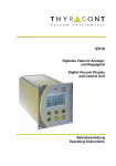
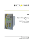
VD10 Digitales Vakuum Anzeigeund Regelgerät Digital Vacuum Display and Control Unit Betriebsanleitung Operating Instructions 2 Inhalt 1 2 Hinweise für Ihre Sicherheit....................................................... 3 Das Anzeige- und Regelgerät VD10 ........................................... 4 2.1 Zur Orientierung...................................................................... 4 2.2 Lieferumfang........................................................................... 4 2.3 Produktbeschreibung .............................................................. 5 3 Installation .................................................................................. 7 3.1 Hinweise zur Installation ......................................................... 7 3.2 Netzanschluss ........................................................................ 7 3.3 Transmitter-Anschluss RS485 ................................................. 8 3.4 Transmitter-Anschluss 0-10 V ................................................. 9 3.5 Schalt-Ausgänge ...................................................................10 3.6 USB-Anschluss ......................................................................10 4 Betrieb .......................................................................................11 4.1 Inbetriebnahme ......................................................................11 4.2 Menu PRESSURE - Absolutdruckanzeige ..............................12 4.3 Menu SENSOR – Parameter und Funktionen.........................13 4.4 Menu RELAY - Schaltausgänge .............................................16 4.5 Menu DISPLAY - Anzeigeoptionen.........................................18 5 Kommunikation .........................................................................19 5.1 Kommunikationsprotokoll .......................................................19 5.2 Befehlsübersicht ....................................................................20 6 Wartung und Service .................................................................21 7 Technische Daten ......................................................................23 Konformitätserklärung ......................................................................24 Hersteller / Manufacturer: Thyracont Vacuum Instruments GmbH Max Emanuel Straße 10 D 94036 Passau Tel.: ++49/851/95986-0 Fax.: ++49/851/95986-40 email: [email protected] Internet: http://www.thyracont.com vd10s8-de-131129 3 1 Hinweise für Ihre Sicherheit Lesen und befolgen Sie alle Punkte dieser Anleitung Informieren Sie sich über Gefahren, die vom Gerät ausgehen und Gefahren, die von Ihrer Anlage ausgehen Beachten Sie die Sicherheits- und Unfall-Verhütungsvorschriften Prüfen Sie regelmäßig die Einhaltung aller Schutzmaßnahmen Installieren Sie das VD10 unter Einhaltung der entsprechenden Umgebungsbedingungen; die Schutzart ist IP20, d.h. die Geräte sind geschützt gegen Eindringen von Fremdkörpern Beachten Sie beim Umgang mit den verwendeten Prozessmedien die einschlägigen Vorschriften und Schutzmaßnahmen Berücksichtigen Sie mögliche Reaktionen zwischen Werkstoffen und Prozessmedien Berücksichtigen Sie mögliche Reaktionen der Prozessmedien infolge der Eigenerwärmung des Produkts Gerät nicht eigenmächtig umbauen oder verändern Informieren Sie sich vor Aufnahme der Arbeiten über eine eventuelle Kontamination Beachten Sie im Umgang mit kontaminierten Teilen die einschlägigen Vorschriften und Schutzmaßnahmen Legen Sie beim Einsenden des Gerätes eine Kontaminationsbescheinigung bei Geben Sie die Sicherheitsvermerke an andere Benutzer weiter Piktogramm-Definitionen Gefahr eines elektrischen Schlages beim Berühren der Kontakte Gefahr von Personenschäden Gefahr von Schäden an Gerät oder Anlage Wichtige Information über das Produkt, dessen Handhabung oder den jeweiligen Teil der Betriebsanleitung, auf den besonders aufmerksam gemacht werden soll vd10s8-de-131129 4 2 Das Anzeige- und Regelgerät VD10 2.1 Zur Orientierung Diese Betriebsanleitung ist gültig für das Produkt mit der Artikelnummer VD10S8. Sie finden die Artikelnummer auf dem Typenschild. Technische Änderungen ohne vorherige Anzeige sind vorbehalten. 2.2 Lieferumfang Zum Lieferumfang gehören: VD10 Anzeige- und Regelgerät Netzkabel Gegenstecker f. Relaisausgang Befestigungsschrauben zur Schalttafelmontage (19"-System) Betriebsanleitung Lieferbares Zubehör: -4 Smartline Transmitter VSR, 1200 – 1x10 mbar -4 Smartline Transmitter VSP, 1000 – 1x10 mbar -9 Smartline Transmitter VSM, 1000 – 5x10 mbar -10 Smartline Transmitter VSH, 1000 – 5x10 mbar Messkabel f. Smartline Transmitter 2m, W1515002 Messkabel f Smartline Transmitter 6m, W1515006 -4 Transmitter VSP63MV, 1000 – 1x10 mbar Messkabel f. VSP63MV, 2m, W0606002 Messkabel f. VSP63MV, 6m, W0606006 USB-Kabel zum PC-Anschluss, 2m, WUSB0002 Windows-Software VacuGraph, VGR vd10s8-de-131129 5 2.3 Produktbeschreibung Das VD10 dient zum Anzeigen und Regeln von Absolutdruck in Verbindung mit Thyracont Vakuum-Transmittern der Smartline. Es können bis zu 4 Messkanäle gleichzeitig angezeigt und geregelt werden. Über eine serielle Schnittstelle lässt sich der Regler vom PC aus steuern. 1 2 3 4 5 6 7 8 9 10 11 12 LCD Graphikdisplay Taste Set Taste Menu Funktionstasten Pfeiltasten auf/ab Gerätesicherung 2,0AT Netzschalter Netzanschluss 95 – 265 VAC, 50/60 Hz USB Schnittstelle 2x Signaleingang 0-10V für VSP63MV Transmitter-Anschluss RS485 für Smartline Transmitter Relaiskontakte vd10s8-de-131129 6 Bestimmungsgemäße Verwendung Das VD10 dient in Verbindung mit Transmittern der Firma Thyracont zur Messung und Regelung von Absolutdruck. Es darf nur an geeignete und hierfür vorgesehene Komponenten angeschlossen werden. Nicht bestimmungsgemäße Verwendung Als nicht bestimmungsgemäß gilt der Einsatz zu Zwecken, die von oben genannten abweichen, insbesondere: der Anschluss an Geräte oder Komponenten, die laut ihrer Betriebsanleitung hierfür nicht vorgesehen sind der Anschluss an Geräte, die berührbare, spannungsführende Teile aufweisen. Bei nicht bestimmungsgemäßem Einsatz erlischt jeglicher Haftungs- und Gewährleistungsanspruch Die Verantwortung im Zusammenhang mit den verwendeten Prozessmedien liegt beim Betreiber. vd10s8-de-131129 7 3 Installation 3.1 Hinweise zur Installation Keine eigenmächtigen Umbauten oder Veränderungen am Gerät vornehmen! Vor dem Anschließen der Spannungsversorgung darauf achten, dass der auf dem Typenschild des VD10 angegebene Spannungsbereich mit der örtlichen Netzspannung übereinstimmt. Aufstellungsort: Innenräume Für nicht vollklimatisierte Betriebsräume gilt: Temperatur: +0°C ... +40°C Rel. Luftfeuchte: 5 - 85%, nicht betauend Luftdruck: 860 - 1060 hPa 3.2 Netzanschluss Der Netzstecker darf nur in eine Netzsteckdose mit Schutzkontakt eingesteckt werden. Hierzu sind 3-polige Netzkabel mit fachgerechtem Schutzleiteranschluss zu verwenden. Netzanschlussbuchse: 6: Gerätesicherung 2,0 AT 7: Netzschalter 8: Netzanschluss vd10s8-de-131129 8 3.3 Transmitter-Anschluss RS485 Das VD10 muss sich im ausgeschalteten Zustand befinden, wenn Transmitter angeschlossen werden. Nichtbeachten dieser Anweisung kann zu Schäden am Gerät führen. 8 15 1 9 An diesen Anschluss des Geräts können Thyracont Smartline-Transmitter für Absolutdruck mit digitalem Signalausgang RS485 angeschlossen werden. Die Transmitter werden vom VD10 mit Strom versorgt. SubD, 15polig, männlich Pin 1: Pin 2,3: Pin 4: Pin 5: Pin 6-9: Pin 10: Pin 11: Pin 12: Pin 13-15: Identifikation n.c. Spannungsversorgung 24 VDC Spannungsversorgung GND n.c. RS485 + RS485 Shield n.c. Transmitter am digitalen RS485-Anschluss können beliebig den Kanalnummern 1 bis 4 zugeordnet werden. Dazu befindet sich an den Transmittern ein AdressSchalter. Sind auch analoge Transmitter-Anschlüsse belegt, so können die dort fest zugeordneten Kanalnummern nicht mehr für Transmitter am RS485-Anschluss verwendet werden (siehe Abschnitt 3.4). Die Kommunikation über RS485 läuft gemäß Thyracont-Schnittstellenprotokoll. vd10s8-de-131129 9 3.4 Transmitter-Anschluss 0-10 V Das VD10 muss sich im ausgeschalteten Zustand befinden, wenn Transmitter angeschlossen werden. Nichtbeachten dieser Anweisung kann zu Schäden am Gerät führen. An diesen beiden Buchsen des Geräts können Thyracont Pirani Transmitter für Absolutdruck Typ VSP63MV mit 0 - 10 V Signalausgang angeschlossen werden. Die Transmitter werden vom VD10 mit Strom versorgt. 1 6 5 Amphenol Pin 1: Pin 2: 3 Pin 3: Pin 4: 4 Pin 5: Pin 6: 2 C91E, 6pol, weiblich Identifikation n.c. Signaleingang, 0-10V GND 24 VDC, max. 8W AGND Für die beiden analogen Transmitter-Anschlüsse existiert eine feste Kanalzuordnung zu Kanal 1 bzw. Kanal 2. Ist also ein Analoganschluss belegt, so kann die betreffende Kanalnummer nicht mehr für Transmitter am digitalen RS485Anschluss verwendet werden! Beispiele: Kanal 1: analog, VSP63MV Kanal 2: analog, VSP63MV Kanal 1, 2: analog, VSP63MV Kanal 2, 3, 4 können digital belegt werden Kanal 1, 3, 4 können digital belegt werden Kanal 3, 4 können digital belegt werden vd10s8-de-131129 10 3.5 Schalt-Ausgänge Beigelegten Gegenstecker zum Verdrahten verwenden. Stecker nur in spannungsfreiem Zustand anschließen, anstecken oder abziehen. Ausgänge mit max. 2 A / 40 VDC bzw. 3 A /250 VAC belasten. Phoenix Combicon, 16polig Darstellung der Kontakte in Ruhelage, d.h. Schaltfunktion "aus" Zur externen Steuerung stehen die Schaltfunktionen des VD10 in Form von 8 Relais-Schaltausgängen (Schließer) SP1 bis SP8 zur Verfügung. Die Schaltausgänge können den verschiedenen Messkanälen oder Funktionstasten frei zugeordnet werden (vgl. Abschnitt 4.4) 3.6 USB-Anschluss 1: 2: 3: 4: 5: Minibuchse Typ B VCC, +5V Data – Data + GND GND Der USB-Anschluss kann mit einem PC verbunden werden, um in z.B. in VerbinTM dung mit der Windows-Software VacuGraph Messungen zu dokumentieren. vd10s8-de-131129 11 4 Betrieb 4.1 Inbetriebnahme Zunächst den oder die verwendeten Vakuumtransmitter an die entsprechenden Signaleingänge RS485 bzw. 0-10V anschließen. Die benötigten Steuerleitungen der Schaltausgänge sind entsprechend den Anforderungen zu verkabeln. Zuletzt das Netzkabel anstecken. Nach dem Einschalten des Netzschalters führt das Gerät zunächst einen Selbsttest durch und zeigt im Display die Versionsnummer der Gerätesoftware an. Anschließend werden die angeschlossenen Transmitter erfasst, hierbei erscheint die Anzeige "scan". Angeschlossene Transmitter werden nur beim Einschalten des VD10 erkannt! Das Gerät befindet sich nun im Anzeigemodus / Menu PRESSURE. Falls der Regler –wie in Abschnitt 4.5 beschrieben- startaktiv konfiguriert wurde (start active "on"), steuert das VD10 simultan mit der Anzeige der Druck-Istwerte bereits die Relais-Schaltausgänge. Tastenbeschreibung: Menu-Auswahl (Umschalten auf das nächste Menu) set Start/Stop-Funktion für Regelung (s. Abschnitt 4.2) Bestätigung eingestellter Werte und Umschalten auf die nächste Eingabeposition (blinkend invers dargestellt) Eingabewert inkrementieren Eingabewert dekrementieren F1 Funktionstaste F1 F2 Funktionstaste F2 vd10s8-de-131129 12 4.2 Menu PRESSURE - Absolutdruckanzeige Im Anzeigemodus wird im Display der momentan gemessene Absolutdruck dargestellt. Die Druckanzeige erfolgt oberhalb 1 mbar (Torr...) numerisch, unterhalb in Exponentialdarstellung. Darüberhinaus werden Kanalnummer (ch: …), Reglerstatus (active/inactive) und -je nach Darstellungsart- die Relaiszustände angezeigt. Der Status der Relais-Schaltausgänge wird hierbei über die Ziffern 1 bis 8 angezeigt, wobei die Ziffern am unteren Display-Rand groß dargestellt werden, sobald das zugehörige Relais eingeschaltet ist. Folgende Anzeigearten können gewählt werden (s. Abschnitt 4.5): Einzelkanal-Anzeige digital Einzelkanal-Anzeige analog Mehrkanal-Anzeige digital vd10s8-de-131129 13 Bei Einzelkanal-Anzeige kann mit den Pfeiltasten zwischen den Messkanälen umgeschaltet werden. Menu-Auswahl (Umschalten zum nächsten Menu) set Im Menu PRESSURE kann mit der set-Taste die Regelung aktiviert bzw. gestoppt werden. 4.3 Menu SENSOR – Parameter und Funktionen Im Menu Sensor werden Kanalnummer, Sensortyp und die jeweils zugehörigen Sensorparameter bzw. Sensorfunktionen angezeigt. Eingabewert mit den Pfeiltasten einstellen. set Eingabe bzw. eingestellten Wert bestätigen und Umschalten zum nächsten Parameter (blinkend invers dargestellt) channel: Kanal auswählen type: Transmittertyp (nicht editierbar) vd10s8-de-131129 14 corr: Gasart-Korrekturfaktor einstellen Bei Totaldruck-Transmittern, die ein gasartabhängiges Messprinzip verwenden, kann zur Anpassung der Druckanzeige ein GasartKorrekturfaktor eingegeben werden. Dadurch wird im Bereich unter 0,1 mbar wieder eine korrekte Druckanzeige erzielt. Der Wert des einzustellenden Faktors ist der Betriebsanleitung des verwendeten Transmitters oder geeigneter Fachliteratur zu entnehmen. Der Wertebereich des Korrekturfaktors reicht von 0,20 bis 8,00. Bei Kombisensoren können separate Faktoren für beide Sensoren eingegeben werden, der Sensortyp wird hochgestellt hinter dem Zahlenwert des Faktors angezeigt, z.B. PI für Pirani, CC für Magnetron (Kaltkathode) oder BA für Bayard Alpert (Heißkathode). trMode: Übergangsmodus wählen Bei Totaldruck-Transmittern mit Kombisensoren ist einstellbar, ob im Übergangsbereich beider Sensoren eine harte Umschaltung zwischen den Sensoren ("switch") oder eine kontinuierliche Wertangleichung ("trans") erfolgen soll. ion/fil: Ionisationssensor aktivieren/deaktivieren Bei Totaldruck-Transmittern mit Kombisensorik kommt für den Hochvakuumbereich ein Ionisationssensor (Heiß- oder Kaltkathode) zum Einsatz. Bei bestimmten Prozess-Schritten kann es gewünscht sein, das von der Transmitterelektronik automatisch gesteuerte Einschalten des Ionisationssensors zu unterdrücken. "off" kein Einschalten des Ionisationssensors "on" automatisches Ein- und Abschalten Bei deaktiviertem Ionisationssensor verhalten sich die Transmittertypen VSM und VSH wie reine Pirani-Messumformer mit -4 Messbereich 1000 - 1x10 mbar. Entsprechend bedeutet die Aus-4 gabe "ur" in diesem Fall, dass der Druckwert unterhalb 1x10 mbar liegt. Die unter ion/fil vorgenommenen Einstellungen werden nur temporär gespeichert. Nach Ausfall oder Ausschalten der Spannungsversorgung befinden sich die Transmitter immer im Modus " Ionisationssensor aktiv" ! vd10s8-de-131129 15 degas: Degas-Funktion Heißkathode Ablagerungen und adsorbierte Gasmoleküle auf den Elektroden eines Heißkathodensensors (VSH) können zu erhöhtem Ausgasen im Ultrahochvakuum führen sowie Instabilitäten im Mess-Signal verursachen. In -6 diesem Fall ist es angebracht, bei einem Druck unterhalb 2.0x10 mbar die Anode des Sensors durch Ausheizen zu reinigen. Die Anode erwärmt sich dabei durch ohmsche Heizung auf bis zu 800°C. Zum Ausheizen den Parameter auf "on" setzen und mit der set-Taste bestätigen. Der Ausheizvorgang wird nach ca. 3 Minuten selbständig beendet, kann jedoch jederzeit ausgeschaltet werden indem der DegasParameter wieder auf "off" gestellt wird. Während des Ausheizvorgangs werden keine aktuellen Messwerte ausgegeben! Das Einschalten der Degas-Funktion ist bei deaktivierter Heißkathode (fil "off") nicht möglich. adjust: Transmitter nachjustieren Die Transmitter sind ab Werk bei Versorgungsspannung 24V stehend, d.h. mit dem Flansch nach unten, abgeglichen. Andere Einbaulagen, Einsatz unter anderen klimatischen Bedingungen, extreme Temperaturschwankungen, Alterung oder Verschmutzung können ein Nachjustieren erforderlich machen. Bei den Transmittern VSM und VSH mit Kombisensoren betrifft das Nachjustieren ausschließlich den Pirani-Sensor. Heiß- und Kaltkathodensensoren werden nicht justiert. Um optimale Ergebnisse beim Nachjustieren zu erzielen, empfehlen wir vor jedem Abgleich eine Warmlaufphase von mindestens 5 Minuten beim jeweiligen Kalibrierdruck zu beach-5 ten. Beim Nullabgleich sollte der Ist-Druck kleiner 5,0x10 mbar sein. Zum Nachjustieren auf Atmosphärendruck den Parameter auf "Hi" setzen und mit der set-Taste bestätigen. Zum Nachjustieren auf Nulldruck den Parameter auf "Lo" setzen und mit der set-Taste bestätigen. vd10s8-de-131129 16 4.4 Menu RELAY - Schaltausgänge Im Menu RELAY erfolgen die Zuordnung der Relais-Schaltausgänge sowie die Einstellung der Relais-Parameter. rel: Relais-Nummer auswählen - - >: Relais-Zuordung einstellen Jedes Relais kann alternativ einem Messkanal ("ch1" bis "ch4") oder einer Funktionstaste ("F1" oder "F2") zugeordnet bzw. direkt auf "on" oder "off" gesetzt werden. Ist ein Relais der Funktionstaste F1 oder F2 zugeordnet, so kann es über die Taste am Gerät manuell geschaltet werden. Die Einstellung "on" wird wirksam, sobald die Regelung eingeschaltet ist. set: Sollwert einstellen Der Sollwert ist über den gesamten Messbereich einstellbar. Es ist jedoch darauf zu achten, dass der Sollwert mindestens um den Wert der eingestellten Hysterese von den Messbereichsgrenzen entfernt liegt. hyst: Schalt-Hysterese einstellen Die Hysterese kann bis zu 90% des Sollwertes betragen. Zu kleine Werte für die Hysterese können ein "Flackern" des zugehörigen Relais zur Folge haben! vd10s8-de-131129 17 mode: Schaltverhalten Für das Schaltverhalten eines Relais können die Einstellungen "normal" oder "invers" gewählt werden. Zur Erläuterung siehe Abbildung unten. Ist die Regelung aktiv, werden die Relais entsprechend dieser Konfiguration geschaltet. Der Status der Relais-Schaltausgänge wird über die Ziffern 1 bis 8 angezeigt, wobei die Ziffern am unteren Display-Rand groß dargestellt werden, sobald das zugehörige Relais eingeschaltet ist. Werden zwei Relais mit Schaltverhalten "normal" und "invers" einem Kanal zugeordnet, so lässt sich damit eine DreipunktRegelung für diesen Kanal realisieren. vd10s8-de-131129 18 4.5 Menu DISPLAY - Anzeigeoptionen Im Menu DISPLAY werden Anzeigenoptionen sowie der Startmodus der Regelung eingestellt. unit: Anzeige-Einheit wählen Einstellbar sind mbar, Torr, Pa, hPa. display mode: Anzeige-Art wählen digital Einkanal-Anzeige digital analog Einkanal-Anzeige analog (Bargraph) multi Mehrkanal-Anzeige digital (vgl. Abschnitt 4.2) start active: Startmodus der Regelung on Die Regelung ist start-aktiv, d.h. die Relais werden angesteuert, sobald das Gerät eingeschaltet und der automatische Selbsttest beendet ist. off Die Regelung muss nach Einschalten des Geräts manuell gestartet und gestoppt werden. (vgl. Abschnitt 4.1 und 4.2) Ein Starten oder Stoppen der Regelung per Softwarebefehl über die serielle Schnittstelle ist unabhängig von den hier gemachten Einstellungen in jedem Falle möglich. vd10s8-de-131129 19 5 Kommunikation 5.1 Kommunikationsprotokoll Die Kommunikation über die serielle Schnittstelle des VD10 erfolgt gemäß Thyracont-Protokoll. Die Befehle werden in folgendem Rahmen als Zeichenfolge im ASCII-Code übertragen: Address Address: Code: Data: cks: CR: Code Data cks CR 3 Bytes, dezimal; 1 Byte, Befehlsparameter, Großbuchstaben für Lesen, Kleinbuchstaben für Schreiben Datenfeld, max. 6 Bytes; kann je nach Code auch fehlen 1 Byte, Checksumme, definiert als Summe über alle ASCII Codes der Felder Adresse, Code und Data, modulo 64 plus 64. Carriage Return (0Dh, 13d) Datenformate: BOOLEAN STRING: UNSIGNED INT: FLOAT: 1 Byte max. 6 Bytes 6 Bytes mit führenden Nullen 6 Bytes, Exponentialformat 4 Bytes Mantisse (entspricht Mantissenwert x 1000) 2 Bytes Exponent, Offset 20 FLOAT-Werte werden in hPa (mbar) übertragen! -4 Beispiel: Der Wert "460016" in einem Float-Datenfeld steht für 4.6x10 mbar. Schnittstellen-Parameter: 9600 baud, 8 Datenbits, 1 Stopbit, keine Parität vd10s8-de-131129 20 5.2 Befehlsübersicht Über die serielle Schnittstelle des VD10 sind folgende Funktionen verfügbar: Befehlstyp Code Datentyp Funktion Gerätetyp Messwert Regelung start/stop Tastaturverriegelung T M A, a K, k STRING FLOAT BOOLEAN BOOLEAN lesen lesen lesen A, schreiben a lesen K, schreiben k Zur Abfrage von Transmitter-Typ oder Messwerten der Kanäle 1 bis 4 sind entsprechend die Adress-Einstellungen "001" bis "004" zu verwenden. Folgende Datenstrings sind als Antwort auf eine Typanfrage möglich: "V10205" Messkanal VD10 mit VSR "V10206" Messkanal VD10 mit VSP "V10207" Messkanal VD10 mit VSM "V10208" Messkanal VD10 mit VSH Für die Befehls-Parameter "a/A" und "k/K" kann Adresse "001" verwendet werden. Beispiele: Aktion Messwert Kanal 4 lesen Telegramm an VD10 C "004Ma R" Regelung starten "001a1c R" C Antwort-Telegramm vom VD10 C "001M260014N R" ( 2.6x10⁻⁶ mbar) C "001a1c R" Für weitere Informationen beachten Sie bitte die gesonderte Beschreibung des Thyracont-Kommunikationsprotokolls. vd10s8-de-131129 21 6 Wartung und Service Vorsicht bei kontaminierten Teilen! Es kann zu Gesundheitsschäden kommen. Informieren Sie sich vor Aufnahme der Arbeiten über eine eventuelle Kontamination. Beachten Sie beim Umgang mit kontaminierten Teilen die einschlägigen Vorschriften und Schutzmaßnahmen. Das Gerät ist wartungsfrei. Äußerliche Verschmutzungen können mit einem feuchten Tuch beseitigt werden. Sollte wider Erwarten ein Schaden an Ihrem VD10 auftreten, senden Sie das Gerät bitte mit einer Kontaminationserklärung zur Reparatur an uns. Das Gerät ist nicht zur kundenseitigen Reparatur vorgesehen! Meldungen Anzeige Mögliche Ursache Behebung "Err1" Druck-Transmitter defekt Transmitter zur Reparatur einschicken "notr" Verbindung zum Transmitter unterbrochen Transmitter, Steckverbindungen und Leitung überprüfen "ur" Messbereich unterschritten "or" Messbereich überschritten "off" Kanal nicht belegt, kein Druck-Transmitter angeschlossen "degas" VSH82 befindet sich im Degas-Modus Gegebenenfalls Transmitter, Steckverbindungen und Leitung überprüfen vd10s8-de-131129 22 vd10s8-de-131129 23 7 Technische Daten Anzeige Display Refresh Rate Abtastrate LCD-Grafikdisplay, hintergrundbeleuchtet, 4stellig, 57 x 35 mm, Gleitpunkt: 2 - 4stellig, exponentiell, 2stellige Mantisse, 1stelliger Exponent 2 Hz (0,5 s) Spannungsversorgung 5 Hz (200 ms) pro Kanal (RS485-Schnittstelle, digital) 30 Hz (33 ms) pro Kanal (0 - 10 V Eingang, analog) 95 – 265 VAC, 50/60 Hz Leistungsaufnahme max. 45 W inklusive Transmitter Sicherung 2,0 A/T Umgebungstemperatur 5...40 C Lagertemperatur -20...+60 C Messeingänge Serielle Schnittstelle 1 x RS485, SubD, 15polig, männl., für Smartline Transmitter 2 x 0 - 10V Amphenol C91E, 6polig, weiblich, für VSP63MV 8 x Relais, Schließer, SP frei zuordenbar, Phoenix Klemmleiste 16-polig, Lebensdauer > 1.000.000 Zyklen, 3 A, 250 VAC, 2 A 40 VDC Mini-USB, Typ B, 5polig Schutzart IP 20 Gewicht 1100 g Schaltausgänge o o vd10s8-de-131129 24 Konformitätserklärung vd10s8-de-131129 25 Content 1 2 3 4 5 6 7 Safety Instructions ................................................................... 26 The VD10 Display and Control Unit ......................................... 27 2.1 For Orientation ...................................................................... 27 2.2 Delivery Content ................................................................... 27 2.3 Product Description............................................................... 28 Installation ................................................................................ 30 3.1 Notes for Installation ............................................................. 30 3.2 Mains Connection ................................................................. 30 3.3 Transducer Connection RS485 ............................................. 31 3.4 Transducer Connection 0-10 V.............................................. 32 3.5 Switching Outputs ................................................................. 33 3.6 USB Interface ....................................................................... 33 Operation .................................................................................. 34 4.1 Startup .................................................................................. 34 4.2 Menu PRESSURE – Pressure Reading................................. 35 4.3 Menu SENSOR – Parameters and Functions ........................ 36 4.4 Menu RELAY - Switching Outputs ......................................... 39 4.5 Menu DISPLAY – Display Settings ........................................ 41 Communication ........................................................................ 42 5.1 Communication Protocol ....................................................... 42 5.2 Survey of Commands............................................................ 43 Maintenance and Service ......................................................... 44 Technical Data .......................................................................... 46 Declaration of Conformity ................................................................ 47 Hersteller / Manufacturer: Thyracont Vacuum Instruments GmbH Max Emanuel Straße 10 D 94036 Passau Tel.: ++49/851/95986-0 Fax.: ++49/851/95986-40 email: [email protected] Internet: http://www.thyracont.com vd10s8-de-131129 26 1 Safety Instructions Read and follow the instructions of this manual Inform yourself regarding hazards, which can be caused by the product or arise in your system Comply with all safety instructions and regulations for accident prevention Check regularly that all safety requirements are being complied with Take account of ambient conditions when installing your VD10. The protection class is IP 20, which means the unit is protected against penetration of foreign bodies. Adhere to the applicable regulations and take the necessary precautions for the process media used Consider possible reactions between materials and process media Consider possible reactions of the process media due to the heat generated by the product Do not carry out any unauthorized conversions or modifications on the unit Before you start working, find out whether any of the vacuum components are contaminated Adhere to the relevant regulations and take the necessary precautions when handling contaminated parts When returning the unit to us, please enclose a declaration of contamination Communicate the safety instructions to other users Pictogram-Definition Danger of an electric shock when touching Danger of personal injury Danger of damage to the unit or system Important information about the product, it's handling or about a particular part of the documentation, which requires special attention vd10s8-de-131129 27 2 The VD10 Display and Control Unit 2.1 For Orientation These operating instructions describe installation and operation of the product with article number VD10S8. The article number can be found on the product's type label. Technical modifications are reserved without prior notification. 2.2 Delivery Content Included in the delivery consignment are: VD10 display and control unit mains cable counter plug for relay outputs fasteners for panel installation (19" system) operating instructions Available accessories: -4 Smartline transducer VSR, 1200 – 1x10 mbar -4 Smartline transducer VSP, 1000 – 1x10 mbar -9 Smartline transducer VSM, 1000 – 5x10 mbar -10 Smartline transducer VSH, 1000 – 5x10 mbar Measuring cable f. Smartline transducer 2m, W1515002 Measuring cable f Smartline transducer 6m, W1515006 -4 transducer VSP63MV, 1000 – 1x10 mbar Measuring cable f. VSP63MV, 2m, W0606002 Measuring cable f. VSP63MV, 6m, W0606006 USB-cable for PC-connection, 2m, WUSB0002 Windows-Software VacuGraph, VGR vd10s8-de-131129 28 2.3 Product Description The VD10S8 is designed to display and control absolute pressure. You can connect Thyracont Smartline vacuum transducers. Up to 4 measuring channels can be displayed and controlled simultaneously. Via serial interface the instrument can be controlled by a PC. 1 2 3 4 5 6 7 8 9 10 11 12 LCD graphic display Set key Menu Function keys Up/Down keys Fuse 2.0 AT Mains switch Mains connector 95 – 265 VAC, 50/60 Hz USB interface 2x signal input 0-10V f. VSP63MV Transducer connection RS485 for Smartline transducers Relay contacts vd10s8-de-131129 29 Proper Use The VD10 serves exclusively to display and control absolute pressure in combination with Thyracont vacuum transducers. It may only be connected to components specifically provided for such purpose. Improper Use The use for purposes not covered above is regarded as improper, in particular: the connection to components not allowed for in their operating instructions the connection to components containing touchable, voltage carrying parts. No liability or warranty will be accepted for claims arising from improper use. The user bears the responsibility with respect to the used process media. vd10s8-de-131129 30 3 Installation 3.1 Notes for Installation Unauthorized modifications or conversions of the instrument are not allowed! Before connecting to mains power make sure that the supply voltage range stated on the type label complies with your local mains voltage. Installation location: Indoor For not fully air conditioned open buildings and operation rooms: Temperature: +0°C ... +40°C Rel. Humidity: 5 - 85%, not condensing Air pressure: 860 - 1060 hPa 3.2 Mains Connection The mains connector must be plugged into a mains socket with protective earth conductor. Use three-pole cables, only, with properly wired earth conductor. Mains connector: vd10s8-de-131129 6: Fuse 2.0 AT 7: Mains switch 8: Socket for mains cable 31 3.3 Transducer Connection RS485 The instrument must be switched off before any transducers are connected. Disregarding this instruction may lead to damage of the instrument. 8 15 1 9 To this port Thyracont Smartline transducers for absolute pressure with digital signal output can be connected. The VD10 provides voltage supply for the transducers. SubD, 15pin, male Pin 1: Pin 2,3: Pin 4: Pin 5: Pin 6-9: Pin 10: Pin 11: Pin 12: Pin 13-15: Identification n.c. Voltage supply 24 VDC Voltage supply GND n.c. RS485 + RS485 Shield n.c. Transducers connected to the RS485 interface can be arbitrarily assigned to channel 1 to 4. For this purpose the transducers are equipped with an addressswitch. If analog transducer ports are used at the same time, the fixed channel numbers assigned to those analog ports cannot be applied as an address for digital transducers (see chapter 3.4). Communication via RS485 is carried out according to the Thyracont protocol. vd10s8-de-131129 32 3.4 Transducer Connection 0-10 V The instrument must be switched off before any transducers are connected. Disregarding this instruction may lead to damage of the instrument. To this port Thyracont transducers type VSP63MV for absolute pressure with 0 - 10 V signal output can be connected. The VD10 provides voltage supply for the transducers. 1 6 5 Amphenol Pin 1: Pin 2: 3 Pin 3: Pin 4: 4 Pin 5: Pin 6: 2 C91E, 6-pole,female Identification n.c. Signal input, 0-10V GND 24 VDC, max. 8W AGND Channel 1 Channel 2 Transducers connected to the analog signal inputs have a fixed assignment to channel 1 or channel 2. If an analog transducer connection is used, the corresponding channel(s) cannot be applied as an address for digital transducers at the RS485 port! Examples: channel 1: analog, VSP63MV channel 2, 3, 4 can be assigned to RS485 channel 2: analog, VSP63MV channel 1, 3, 4 can be assigned to RS485 channel 1, 2: analog, VSP63MV channel 3, 4 can be assigned to RS485 vd10s8-de-131129 33 3.5 Switching Outputs Use enclosed counter plug for electrical connection. Connect only when power is off. Maximum load for the relays is 2 A / 40 VDC or 3 A / 250 VAC. Phoenix Combicon, 16pin The contacts are shown in state-of-rest position, i.e. switching function "off" For process control this output of the VD10 provides switching functions by means of 8 relay switches (closer) SP1 to SP8. The switching outputs can be assigned to measuring channels 1 to 4 or function keys F1 or F2 (s. chapter 4.4). 3.6 USB Interface 1: 2: 3: 4: 5: Mini socket, type B VCC, +5V Data – Data + GND GND The USB-interface can be connected to a PC, e.g. for documentation of TM measurements in combination with Windows-Software VacuGraph . vd10s8-de-131129 34 4 Operation 4.1 Startup First connect the required transducers to the corresponding signal inputs 0-10V or RS485. The control lines of the relay outputs or are to be wired according to the particular requirements. At last the mains cable has to be connected. When switched-on the VD10 performs a self-test and displays the software version. Afterwards the VD10 scans for connected vacuum transducers while the display shows "scan". Connected transducers are only detected during this start procedure! Now the VD10 is operating in display mode / Menu PRESSURE. If the controller is configured to start mode "run" (start active "on") –as described in chapter 4.5- the VD10 actuates the relay switches simultaneously with the display of actual pressure. Description of keys: Menu-selection (switch to the next menu) set Start/Stop-function for controlling (s. chapter 4.2) Confirmation of adjusted values and change to the next input position (flashing inversely) Increment input value Decrement input value F1 Function key F1 F2 Function key F2 vd10s8-de-131129 35 4.2 Menu PRESSURE – Pressure Reading In display mode the VD10 shows the actual absolute pressure. Reading is numerical above 1 mbar (Torr, …) and exponential below. Further the VD10 display indicates channel number (ch: …), control status (active/inactive) and –depending on the display mode- the states of the relay switches. The state of the switching outputs is indicated by figures 1 to 8 at the bottom of the display. The figures are enlarged as soon as the corresponding relay is switched on. The following display modes can be selected (see chapter 4.5): One-Channel-Display digital One-Channel-Display analog Multi-Channel-Display digital vd10s8-de-131129 36 In one-channel display you can switch to the next/previous channel number by means of the up/down keys. Menu-selection (switch to next Menu) set In menu PRESSURE controlling can be activated and stopped by means of the set-key. 4.3 Menu SENSOR – Parameters and Functions The sensor menu shows channel number, sensor type and the associated sensor parameters and functions. Adjust input value by means of the up/down keys. set Confirm changes and switch to the next parameter (flashing inversely) channel: Select channel number type: Transducer type (cannot be edited) vd10s8-de-131129 37 corr: Set gas type correction factor For transducers whose measurement depends on the type of gas you can enter a correction factor for compensation. This way the pressure reading can be corrected in a range below 0.1 mbar. Appropriate correction factors are found in the operating instructions of the transducer or suitable technical literature. The range of the gas type correction factor is 0.20 to 8.00. For transducers with combination sensors separate factors for both sensors can be entered. The associated sensor type is displayed in superscript letters behind the numeric value of the factor, e.g. PI for Pirani, CC for Magnetron (cold cathode) and BA for Bayard Alpert (hot cathode). trMode: Select transition mode For transducers with combination sensors you can select whether a hard switch-over ("switch") or a continuous transition ("trans") between the two sensors should be performed in the overlap range. ion/fil: Enable/disable ionization sensor Transducers with combination sensors operate an ionization sensor (hot or cold cathode) for measuring pressure in the high vacuum range. For certain vacuum processes it may be favoured to suppress the start of the ionization sensor, which is automatically controlled by the transducer electronics. "off" ionization sensor disabled "on" automatic control of the ionization sensor With disabled ionization sensor transducers VSM and VSH behave -4 like a Pirani transducer with range 1000 - 1x10 mbar. Correspondingly the output "ur" in this case means that actual pressure is below -4 1x10 mbar. Settings made under ion/fil are only temporarily saved in the transducer memory. After mains supply is switched off or disconnected the transducer will always be in mode "ionization sensor enabled" ! vd10s8-de-131129 38 degas: Degas-function for hot cathode sensor Deposition or adsorbed gas molecules on the electrodes of a hot cathode sensor (VSH) may lead to increased degassing in ultrahigh vacuum or even cause instabilities of the measurement signal. In such cases it is appropriate to clean the anode of the sensor by degassing. This is done -6 at pressures below 2.0x10 mbar by ohmic heating of the anode to temperatures around 800°C. For degassing the sensor set the degas parameter to "on" and confirm with the set-key. The degas procedure will stop automatically after approx. 3 minutes, but can be cancelled any time by setting the parameter to "off" again. During the degas process no actual pressure measurement is available! The degas function cannot be started if the hot cathode is disabled (fil "off"). adjust: Transducer adjustment The transducers are adjusted ex works with 24V voltage supply in upright position, flange to the bottom. Other orientation, operation under different climatic conditions, extreme temperature changes, ageing or contamination can result in the need for readjustment of the Pirani sensor. For transducers VSM and VSH with combination sensors the adjustment does only affect the Pirani sensor. Hot and cold cathode sensors are not readjusted. To achieve optimum results of the adjustment we recommend to consider a warm-up of at least 5 minutes at the appropriate calibration pressure before any adjustment. For zero adjustment actual pressure should be less than -5 5,0x10 mbar. For adjustment on atmosphere pressure set the parameter to "Hi" and confirm with the set-key. For adjustment on zero pressure set the parameter to "Lo" and confirm with the set-key. vd10s8-de-131129 39 4.4 Menu RELAY - Switching Outputs In the RELAY menu you can assign the switching outputs and set relay parameters. rel: Select relay number - - >: Set relay assignment Each relay can alternatively be assigned to a measuring channel ("ch1" to "ch4") or to a function key ("F1" or "F2") or it can be directly set to state "on" or "off". When a relay is assigned to function key F1 or F2 it can be manually switched on and off by that key. Setting "on" becomes effective as soon as controlling is started. set: Adjust setpoint The setpoint is adjustable over the whole measuring range. It is mandatory, however, to consider a minimum distance of the setpoint from the range limits of at least the magnitude of the chosen hysteresis. hyst: Set hysteresis The hysteresis can be set up to 90% of the setpoint. Too small values for the hysteresis may result in a flickering relay! vd10s8-de-131129 40 mode: Switching mode For the switching mode of each relay you can choose between "normal" or "inverse". The diagram below gives an explanation: When controlling is active, the relays are switched according to this configuration. The state of the switching outputs is indicated by figures 1 to 8 at the bottom of the display. The figures are enlarged as soon as the corresponding relay is switched on. For a given channel a three-state-control can be achieved by assigning two relays with switching mode "normal" and "inverse" to that channel. vd10s8-de-131129 41 4.5 Menu DISPLAY – Display Settings In the DISPLAY menu settings for pressure display and the start mode of pressure control are selected. unit: Select display unit Select mbar, Torr, Pa or hPa. display mode: Select display mode digital one-channel display, digital analog one-channel display, analog (bargraph) multi multi-channel display, digital (see also chapter 4.2) start active: Start mode of pressure control on pressure control is start-active, i.e. the relays are switched as soon as the VD10 has finished its automatic selftest procedure after switched-on. off after the VD10 is switched-on pressure control has to be started and stopped manually. (see also chapter 4.1 and 4.2) Independently from these settings pressure control can be started and stopped by software command via serial interface. vd10s8-de-131129 42 5 Communication 5.1 Communication Protocol Communication is carried out according to the Thyracont protocol. The commands are sent as ASCII-code in the following command frame: Address Address: Code: Data: cks: CR: Code Data cks CR 3 Bytes, decimal 1 Byte, command parameter, upper case character for read command, lower case character for write command data field, max. 6 Bytes; can be absent depending on code 1 Byte, checksum, defined as sum over all ASCII codes of the fields address, code and data, modulo 64 plus 64. Carriage Return (0Dh, 13d) Data Formats: BOOLEAN STRING: UNSIGNED INT: FLOAT: 1 Byte max. 6 Bytes 6 Bytes with leading zeros 6 Bytes, exponential format 4 Bytes mantissa (means mantissa value x 1000) 2 Bytes exponent, offset 20 FLOAT-values are transmitted in hPa (mbar)! -4 Example: Value "460016" in a float type data field means 4.6x10 mbar. Interface-Parameters: 9600 baud, 8 data bits, 1 stopbit, no parity vd10s8-de-131129 43 5.2 Survey of Commands By the serial interface of the VD10 the following functions are available: Command Type Measurement Value Control start/stop Keylock Code T M A, a K, k Data Type STRING FLOAT BOOLEAN BOOLEAN Function read read read A, write a read K, write k For reading transducer type or measurements of channel 1 to 4 the corresponding address settings "001" to "004" have to be used. The following data strings are sent as possible answer to type queries: "V10205" measuring channel VD10 with VSR "V10206" measuring channel VD10 with VSP "V10207" measuring channel VD10 with VSM "V10208" measuring channel VD10 with VSH For commands "a/A" and "k/K" address "001" can be used. Examples: Action Read pressure measurement Of channel 4 Start Control Telegram to transducer C "004Ma R" C "001a1c R" Answer telegram from transducer C "004M260014N R" ( 2.6x10⁻⁶ mbar) C "001a1c R" For further information please refer to the separate description of the Thyracont communication protocol. vd10s8-de-131129 44 6 Maintenance and Service Danger of possibly contaminated parts! Contaminated parts can cause personal injuries. Inform yourself regarding possible contamination before you start working. Be sure to follow the relevant instructions and take care of necessary protective measures. The unit requires no maintenance. External dirt and soiling can be removed by a damp cloth. Should a defect or damage occur on the VD10, please send the instrument for repair, enclosing a contamination declaration. The unit is not planned for customer repair! Messages Message Possible Cause Measures "Err1" defective pressure transducer send transducer for repair "notr" connection to transducer interrupted check transducer, connectors and cables "ur" measurement under range "or" measurement over range "off" channel not in use, no transducer connected "degas" VSH82 is in degas mode vd10s8-de-131129 if appropriate check transducer, connectors and cables 45 vd10s8-de-131129 46 7 Technical Data Display Display Refresh Rate Scanning Rate LCD graphic display, with background illumination, 4digits, 57 x 35 mm, floating point: 2 – 4digits, exponential: 2digits mantissa plus exponent 2 Hz (0,5 s) Voltage Supply 5 Hz (200 ms) pro Kanal (RS485-Schnittstelle, digital) 30 Hz (33 ms) pro Kanal (0 - 10 V Eingang, analog) 95 – 265 VAC, 50/60 Hz Power Consumption max. 45 W including transducers Fuse 2,0 A/T Ambient Temperature 5...40 C Storage Temperature -20...+60 C Measuring Input Serial Interface 1 x RS485, SubD, 15pin, male, for Smartline transducers 2 x 0 - 10V Amphenol C91E, 6pin, female, for VSP63MV 8 x relay, closer, SP assignable, Phoenix strip terminal 16-pin, lifetime > 1.000.000 cycles, 3 A, 250 VAC, 2 A 40 VDC Mini-USB, Type B, 5pin Protection Class IP 20 Weight 1100 g Switching Output vd10s8-de-131129 o o 47 Declaration of Conformity vd10s8-de-131129 vd10s8-de-131129