1
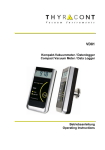
VD6
Digitales Anzeige- und Regelgerät
Digital Display and Control Unit
Betriebsanleitung
Operating Instructions
2
Inhalt
1
2
3
4
5
6
7
Hinweise für Ihre Sicherheit .......................................................... 3
Das Anzeige- und Regelgerät VD6 ............................................... 4
2.1
Zur Orientierung ......................................................................... 4
2.2
Lieferumfang............................................................................... 4
2.3
Produktbeschreibung ................................................................. 4
Installation ...................................................................................... 6
3.1
Hinweise zur Installation............................................................. 6
3.2
Schalttafeleinbau ........................................................................ 7
3.3
Netzanschluss ............................................................................ 7
3.4
Anschluss Vakuum-Transmitter ................................................. 8
3.5
USB Anschluss ........................................................................... 8
3.6
Relais-Ausgänge ........................................................................ 9
3.7
Schreiberausgang .................................................................... 10
Betrieb ........................................................................................... 11
4.1
Inbetriebnahme ........................................................................ 11
4.2
Absolutdruckanzeige ................................................................ 11
4.3
Schaltpunkte ............................................................................. 12
4.4
Regelung starten und stoppen ................................................. 15
4.5
Gasartkorrektur ........................................................................ 15
4.6
Kommunikationsprotokoll ......................................................... 16
4.7
Befehlsübersicht ....................................................................... 16
Konfiguration ................................................................................ 18
5.1
Transmitter Typ ........................................................................ 18
5.2
Schaltverhalten ......................................................................... 19
5.3
Analogausgang ........................................................................ 20
5.4
Startmodus ............................................................................... 22
Wartung und Service ................................................................... 23
Technische Daten ........................................................................ 25
Konformitätserklärung ......................................................................... 26
Hersteller:
Thyracont Vacuum Instruments GmbH
Max Emanuel Straße 10
D 94036 Passau
Tel.: +49/851/95986-0
Fax.: +49/851/95986-40
email: [email protected]
Internet: http://www.thyracont.com
3
1
Hinweise für Ihre Sicherheit
Lesen und befolgen Sie alle Punkte dieser Anleitung
Informieren Sie sich über Gefahren, die vom Gerät ausgehen und Gefahren, die von
Ihrer Anlage ausgehen
Beachten Sie die Sicherheits- und Unfall-Verhütungsvorschriften
Prüfen Sie regelmäßig die Einhaltung aller Schutzmaßnahmen
Installieren Sie das VD6 unter Einhaltung der entsprechenden Umgebungsbedingungen; die Schutzart ist IP20, d.h. die Geräte sind geschützt gegen Eindringen von
Fremdkörpern
Beachten Sie beim Umgang mit den verwendeten Prozessmedien die einschlägigen
Vorschriften und Schutzmaßnahmen
Berücksichtigen Sie mögliche Reaktionen zwischen Werkstoffen und Prozessmedien
Berücksichtigen Sie mögliche Reaktionen der Prozessmedien infolge der Eigenerwärmung des Produkts
Gerät nicht eigenmächtig umbauen oder verändern
Informieren Sie sich vor Aufnahme der Arbeiten über eine eventuelle Kontamination
Beachten Sie im Umgang mit kontaminierten Teilen die einschlägigen Vorschriften
und Schutzmaßnahmen
Legen Sie beim Einsenden des Gerätes eine Kontaminationsbescheinigung bei
Geben Sie die Sicherheitsvermerke an andere Benutzer weiter
Piktogramm-Definitionen
Gefahr eines elektrischen Schlages beim Berühren der
Kontakte
Gefahr von Personenschäden
Gefahr von Schäden an Gerät oder Anlage
Wichtige Information über das Produkt, dessen Handhabung
oder den jeweiligen Teil der Betriebsanleitung, auf den besonders aufmerksam gemacht werden soll
4
2 Das Anzeige- und Regelgerät VD6
2.1 Zur Orientierung
Diese Betriebsanleitung ist gültig für Produkte mit den Artikelnummern
VD6S2115 und VD6S2230.
Sie finden die Artikelnummern auf dem Typenschild. Technische Änderungen
ohne vorherige Anzeige sind vorbehalten.
2.2 Lieferumfang
Zum Lieferumfang gehören:
VD6 Anzeige- und Regelgerät
Gegenstecker für Netzbuchse und Schaltausgänge
Gegenstecker für Schreiberausgang
Befestigungsspangen zur Schalttafelmontage
Betriebsanleitung
Lieferbares Zubehör:
Vakuum-Transmitter VSC42MA4, 1400 – 1 mbar
-3
Vakuum-Transmitter VSP52MA4, 100 – 1,0 x 10 mbar
Messkabel 2m, W0900002
Messkabel 6m, W0900006
USB Anschlusskabel 2m, WUSB0002
Windows-Software VacuGraph, VGR
2.3 Produktbeschreibung
Das VD6 dient zum Anzeigen und Regeln von Absolutdruck. Anschließbar sind
hierzu Thyracont Vakuum-Transmitter mit Signalausgang 4-20mA.
Über die USB Schnittstelle des Geräts kann der Regler vom PC aus gesteuert
werden.
5
1
2
3
4
5
6
7
8
9
10
1: LED Display
2: Druckeinheit
3: LED SP1: Schaltpunkt 1 bzw. oberer Schaltpunkt
4: LED: Sollwert bei 3-Punkt-Regelung
5: LED SP2: Schaltpunkt 2 bzw. unterer Schaltpunkt
6: LED: Regelung aktiv
7: Menu-Taste
8: Set-Taste
9: Aufwärts-Taste zum Einstellen von Werten
10: Abwärts-Taste zum Einstellen von Werten
11 12
13
14 15
11: Schreiberausgang
12: Anschluss Vakuum-Transmitter
13: USB Anschluss
14: Relais 1 für Schaltpunkt 1
15: Relais 2 für Schaltpunkt 2
16: Netzanschluss
16
6
Bestimmungsgemäße Verwendung
Das VD6 dient in Verbindung mit Vakuum-Transmittern der Firma Thyracont zur
Messung und Regelung von Absolutdruck. Es darf nur an geeignete und hierfür
vorgesehene Komponenten angeschlossen werden.
Nicht bestimmungsgemäße Verwendung
Als nicht bestimmungsgemäß gilt der Einsatz zu Zwecken, die von oben genannten abweichen, insbesondere:
der Anschluss an Geräte oder Komponenten, die laut ihrer Betriebsanleitung hierfür nicht vorgesehen sind
der Anschluss an Geräte, die berührbare, spannungsführende Teile
aufweisen.
Bei nicht bestimmungsgemäßem Einsatz erlischt jeglicher Haftungs- und
Gewährleistungsanspruch
Die Verantwortung im Zusammenhang mit den verwendeten Prozessmedien
liegt beim Betreiber.
3 Installation
3.1 Hinweise zur Installation
Keine eigenmächtigen Umbauten oder Veränderungen am Gerät
vornehmen! Vor dem Anschließen der Spannungsversorgung darauf achten, dass der auf dem Typenschild des VD6 angegebene
Spannungsbereich mit der örtlichen Netzspannung übereinstimmt.
Aufstellungsort: Innenräume
Für nicht vollklimatisierte Betriebsräume gilt:
Temperatur:
+0°C ... +40°C
Rel. Luftfeuchte:
5 - 85%, nicht betauend
Luftdruck:
860 - 1060 hPa
7
3.2 Schalttafeleinbau
Das Gerät ist zur Schalttafelmontage vorgesehen. Bei
Verwendung als Tischgerät besteht die Gefahr eines elektrischen
Schlages!
Die Größe des benötigten Schalttafel-Ausbruchs beträgt 90 x 42 mm.
Zur Schalttafelmontage sind die mitgelieferten Befestigungsspangen zu verwenden. Das Gerät in den Schalttafelausbruch einschieben und die Spangen -wie in
der Abbildung unten gezeigt- in die seitlich am VD6-Gehäuse angebrachten
Befestigungsknöpfe einhaken. Zur Fixierung die Schrauben von hinten anziehen,
so dass das Gerät von hinten gegen die Schalttafel geklemmt wird.
3.3 Netzanschluss
Kabel nur durch elektrotechnisch geschultes Personal herstellen
oder anpassen lassen. Technische Daten beachten, um Überlastung oder Zerstörung des Geräts bzw. eine Gefahr für den Betreiber zu vermeiden. Die Netzspannung muss über einen
geschalteten Netzverteiler zugeführt werden.
Auf richtige Netzspannung achten, um Schäden am Gerät zu
vermeiden!
VD6S2115: 115 VAC, 50/60 Hz
VD6S2230: 230 VAC, 50/60 Hz
8
3.4 Anschluss Vakuum-Transmitter
Das Gerät muss sich im ausgeschalteten Zustand befinden, wenn
Vakuum-Transmitter angeschlossen werden.
Nichtbeachten dieser Anweisung kann zu Schäden am Gerät führen.
An das Gerät kann ein Thyracont Vakuum-Transmitter für Absolutdruck angeschlossen werden. Zulässige Typen hierfür sind:
VSC42MA4 (1400 – 1 mbar)
-3
VSP52MA4 (100 – 1x10 mbar)
Der Vakuum-Transmitter wird vom VD6 mit Strom versorgt.
1
2
3
4
5
6
7
8
9
SubD
Pin 3:
Pin 4:
Pin 7:
Pin 9:
3.5 USB Anschluss
9pol, weibl.
Input: 4 -20 mA VSP52MA4
Input: 4 -20 mA VSC42MA4
Spannungsversorgung: 15 VDC, max. 1,5 W
AGND (für 3-Leiter Anschluss)
9
1:
2:
3:
4:
5:
Minibuchse Typ B
VCC, +5V
Data –
Data +
GND
GND
Der USB-Anschluss kann mit einem PC verbunden werden, um z.B. in
TM
Verbindung mit der Windows™ Software VacuGraph Druckwerte auszulesen,
Messungen zu dokumentieren oder Sollwerte zu programmieren.
3.6 Relais-Ausgänge
Zur externen Steuerung stehen an diesem Ausgang die
Schaltfunktionen des VD6 in Form von 2 Wechsel-Relais
Schaltpunkten SP1 und SP2 zur Verfügung (Darstellung in
Ruhelage, stromlos, d.h. Schaltfunktion aus).
Beigelegten Gegenstecker zum Verdrahten verwenden. Stecker
nur in spannungsfreiem Zustand anschließen, anstecken oder
abziehen. Ausgänge mit max. 2 A / 250 VAC, 1 A / 30 VDC
(normal closed) bzw. 5 A / 250 VAC, 5 A / 30 VDC (normal open)
ohmsch belastbar.
10
3.7 Schreiberausgang
1
2
1:
2:
Klinkenbuchse
Analog Out, 0-1V / 0-10V, min.10kΩ
AGND
Am Schreiberausgang steht der gemessene Absolutdruck als analoges Spannungssignal zur Verfügung. Der Spannungswert hängt je nach angeschlossenem Vakuum-Transmitter linear oder logarithmisch vom angezeigten Druck ab.
Der Schreiberausgang kann dabei auf 0-1V oder 0-10V konfiguriert werden.
Die Konfiguration sowie der Zusammenhang zwischen angezeigtem Druck und
Ausgangsspannung sind in Abschnitt 5.3 beschrieben.
Der Mindest-Lastwiderstand für den Schreiberausgang
beträgt 10 kΩ.
11
4 Betrieb
4.1 Inbetriebnahme
Zunächst ist der Vakuum-Transmitter entsprechend Abschnitt 3.4 ans VD6 anzuschließen. Sobald die Verbindung mit der Netzversorgung hergestellt ist, erscheinen
folgende Anzeigen:
-
Displaytest (alle Segmente)
Versionsnummer der Firmware
Eingestellter Transmittertyp
gemessener Absolutdruck.
Das Gerät befindet sich nun im Messmodus.
Falls der Regler –wie in Abschnitt 5.4 beschrieben- startaktiv konfiguriert wurde
(Startmodus "run"), steuert das VD6 simultan mit der Anzeige des DruckIstwertes bereits die beiden Relais-Schaltausgänge.
Ansonsten befinden sich die Relais Wechselschalter im Ruhezustand.
Tastenbeschreibung:
Umschaltung zwischen Messmodus und dem Einstellmodus f. Sollwert,
Hysterese bzw. Gasart-Korrekturfaktor.
set
Messmodus: Start/Stop-Funktion für Regelung (s. auch Abschnitt 5.4)
Einstellmodus: Bestätigung der eingestellten Werte
Inkrementieren der Werte im Einstellmodus
Dekrementieren der Werte im Einstellmodus
4.2 Absolutdruckanzeige
Im Messmodus zeigt das Display den momentan gemessenen Absolutdruck.
Die Druckanzeige erfolgt oberhalb 1 mbar (Torr...) numerisch, unterhalb in Exponentialdarstellung.
Der Status der Schaltausgänge wird über die LEDs SP1 und SP2 angezeigt, wobei
die jeweilige LED leuchtet, wenn das zugehörige Relais eingeschaltet ist.
12
4.3 Schaltpunkte
Das VD6 kann –wie unter Abschnitt 5.2 beschrieben- als Zwei- oder DreipunktRegler konfiguriert werden.
Schaltverhalten "2P" (2-Punkt-Regler)
Die Relais-Schaltausgänge SP1 und SP2 werden jeweils mit Sollwert und
zugehöriger Hysterese (H1 bzw. H2) eingestellt. Beide Schaltausgänge arbeiten
voneinander unabhängig.
Die Hysterese liegt jeweils symmetrisch um den Sollwert. Bei Änderung des
Sollwertes wird die zugehörige Hysterese zunächst automatisch über einen
prozentualen Zusammenhang an den neuen Sollwert adaptiert. Eine anschließende manuelle Änderung der Hysterese ist ebenfalls möglich (Werte werden
dabei auf Plausibilität zum Sollwert überprüft).
Beispiel:
Sollwert 1 = 10mbar / H1=1mbar (10% vom Sollwert)
Schaltausgang 1 wird bei 9mbar deaktiviert, bei 11mbar aktiviert.
Änderung Sollwert 1 = 1.0mbar / H1=0.1mbar (automatisch !).
Schaltausgang 1 wird bei 0.9mbar deaktiviert, bei 1.1mbar aktiviert.
13
Zum Einstellen der Schaltpunkte von SP1 (oder SP2):
Taste Menu (mehrmals) drücken, bis rechts neben dem Display die LED für SP1
(bzw. SP2) leuchtet.
Mithilfe der Pfeiltasten den gewünschten Sollwert einstellen.
set
Bestätigen mit der Set-Taste. Im Display erscheint die momentan eingestellte
Hysterese.
Mithilfe der Pfeiltasten die gewünschte Hysterese einstellen. Diese darf
max. 90% des eingestellten Sollwertes betragen.
set
Bestätigen mit der Set-Taste.
Erfolgt 5s lang kein Tastendruck oder wird eine Änderung mit der Taste "Menu"
quittiert, werden die Änderungen verworfen und der ursprüngliche Zustand
wieder angezeigt (Undo-Funktion).
Schaltverhalten "3P" (3-Punkt-Regler)
Die Schaltpunkte werden in Form eines gemeinsamen Sollwertes mit positiver
Hysterese H1 für Evakuierung bzw. negativer Hysterese H2 für Belüftung
eingestellt.
Die Hysteresen können asymmetrisch zum Sollwert liegen. Bei Änderung des
Sollwertes werden die Hysteresen zunächst automatisch über einen prozentualen Zusammenhang an den neu eingegebenen Sollwert adaptiert. Eine anschließende manuelle Änderung der Hysteresen ist ebenfalls möglich (Werte werden
dabei auf Plausibilität zum Sollwert überprüft).
Beispiel: Sollwert = 100mbar / Hysterese H1 = 10mbar, H2 = 20mbar
Schaltausgang für Evakuierung SP1 wird bei 100mbar deaktiviert, bei 110mbar
aktiviert.
Schaltausgang für Belüftung SP2 wird bei 100mbar deaktiviert, bei 80mbar
aktiviert.
14
Zum Einstellen der Schaltpunkte:
Taste Menu (mehrmals) drücken, bis im Display die LED "Sollwert 3-PunktRegelung" leuchtet.
Mithilfe der Pfeiltasten den gewünschten Sollwert einstellen.
set
Bestätigen mit der Set-Taste. Im Display erscheint die momentan eingestellte
Hysterese H1 für Evakuierung.
Mithilfe der Pfeiltasten Hysterese H1 einstellen, diese darf max. 90%
des eingestellten Sollwertes betragen.
set
Bestätigen mit der Set-Taste. Im Display erscheint die momentan eingestellte
Hysterese H2 für Belüftung.
Mithilfe der Pfeiltasten Hysterese H2 einstellen, diese darf max. 90%
des eingestellten Sollwertes betragen.
set
Bestätigen mit der Set-Taste.
15
Erfolgt 5s lang kein Tastendruck oder wird eine Änderung mit der Taste "Menu"
quittiert, werden die Änderungen verworfen und der ursprüngliche Zustand
wieder angezeigt (Undo-Funktion).
4.4 Regelung starten und stoppen
Wird im Display des VD6 der momentan gemessene Absolutdruck angezeigt
(Messmodus), so kann mit der "set"-Taste die Regelung gestartet und gestoppt
werden:
set
Regelung eingeschaltet.
Aktive Schaltausgänge werden durch
LEDs angezeigt.
set
Regelung aus.
4.5 Gasartkorrektur
Bei Totaldruck-Transmittern, die ein gasartabhängiges Messprinzip verwenden,
kann zur Anpassung der Druckanzeige ein Gasart-Korrekturfaktor eingegeben
werden. Dadurch wird in weiten Bereichen wieder eine korrekte Druckanzeige
erzielt.
Der Wert des einzustellenden Faktors ist der Betriebsanleitung des verwendeten
Transmitters oder geeigneter Fachliteratur zu entnehmen. Der Wertebereich des
Korrekturfaktors reicht von 0,20 bis 8,00.
Zum Einstellen des Gasart-Korrekturfaktors:
Taste Menu (mehrmals) drücken, bis im Display der Gasart-Korrekturfaktor "c..."
erscheint.
Per Pfeiltasten den gewünschten Korrekturfaktor einstellen.
set
Bestätigen mit der Set-Taste.
Erfolgt 5s lang kein Tastendruck oder wird eine Änderung mit der Taste "Menu"
quittiert, werden die Änderungen verworfen und der ursprüngliche Zustand
wieder angezeigt (Undo-Funktion).
16
4.6 Kommunikationsprotokoll
Wird die rückseitige Mini USB-Buchse des VD6 durch ein geeignetes Schnittstellen-Kabel (Zubehör WUSB0002) mit einem PC verbunden, so kann z.B. mittels
TM
VacuGraph Software (Zubehör VGR) der Regler vom PC aus via Virtual-ComPort Protokoll gesteuert werden.
Die Kommunikation erfolgt gemäß Thyracont-Protokoll. Die Befehle werden in
folgendem Rahmen als Zeichenfolge im ASCII-Code übertragen:
Adresse
Adresse:
Code:
Data:
cks:
CR:
Data
Code
cks
CR
3 Bytes, dezimal; RS232, USB: 001
1 Byte, Befehlsparameter, Großbuchstaben für Lesen, Kleinbuchstaben für Schreiben
Datenfeld, max. 6 Bytes; kann je nach Code auch fehlen
1 Byte, Checksumme, definiert als Summe über alle Bytes der
Felder Adresse, Code und Data, modulo 64 plus 64.
Carriage Return (0Dh, 13d)
Datenformat:
FLOAT:
6 Bytes, Exponentialformat
4 Bytes Mantisse (entspricht Mantissenwert x 1000)
2 Bytes Exponent, Offset 20
FLOAT-Werte werden in hPa (mbar) übertragen!
-1
Beispiel: Der Wert "460019" in einem Float-Datenfeld steht für 4.6x10 mbar.
4.7 Befehlsübersicht
Über die USB Schnittstelle des VD6 sind folgende Funktionen verfügbar:
Befehlstyp
Code
Datentyp
Funktion
Gerätetyp
Messwert
Schaltpunkt
T
M
S, s
STRING
FLOAT
FLOAT
Hysterese
H, h
FLOAT
Gasart-Korrekturfaktor
Regelung start/stop
Tastaturverriegelung
C, c
A, a
K, k
UNSIGNED INT
BOOLEAN
BOOLEAN
lesen
lesen
lesen S, schreiben s
(SP1 und SP2)
lesen H, schreiben h
(H1 und H2)
lesen C, schreiben c
lesen A, schreiben a
lesen K, schreiben k
17
Beispiele:
Aktion
Telegramm an VD6
Messwert lesen
"001M^ R"
Regelung starten
Schaltpunkt 2 lesen
"001a1c R"
C
"001S2V R"
Unlock Schaltpunkt 2
"001s2v R"
Schaltpunkt 2 auf
4.2x10⁻² mbar setzen
Unlock Gasart-Korrekturfaktor 1
"001s420018s R"
Gasart-Korrekturfaktor 1
auf 1.20 setzen
"001c000120W R"
C
C
C
C
C
Antwort-Telegramm
vom VD6
C
"001M864022T R"
( 8.64x10+2mbar
= 864 mbar)
C
"001a1c R"
C
"001S400018Q R"
( 4.0x10⁻² mbar)
C
"001s2v R"
C
"001s420018s R"
C
"001c1e R"
"001c1e R"
C
C
"001c000120W R"
Vor dem Schreiben der Parameter "s" (Schaltpunkt), "h" (Hysterese) und "c"
(Korrekturfaktor) müssen diese zunächst mit einem Unlock-Befehl freigeschaltet
werden!
Für weitere Informationen beachten Sie bitte die gesonderte Beschreibung des
Thyracont-Kommunikationsprotokolls.
18
5 Konfiguration
Änderungen der Geräte-Konfiguration nur von geschultem
Fachpersonal durchführen lassen!
Um im Konfigurationsmodus Grundeinstellungen des VD6 zu ändern:
beim Einschalten des Gerätes die
"set"-Taste gedrückt halten, bis die
Anzeige "typ .." erscheint.
set
5s
5.1 Transmitter Typ
Das VD6 kann für den Betrieb mit folgenden Vakuum-Transmittern konfiguriert
werden:
Typ1:
Typ3:
VSC42MA4, 1400-1 mbar
-3
VSP52MA4, 100-1x10 mbar
Zum Einstellen des Transmittertyps das VD6 wie unter Abschnitt 5 beschrieben
in den Konfigurationsmodus schalten, so dass die Anzeige "typ .." erscheint.
Der momentan eingestellte Transmittertyp wird angezeigt.
Mithilfe der Pfeiltasten kann nun zwischen den verschiedenen Typen
gewechselt werden.
set
Die Auswahl mit der Set-Taste bestätigen.
Im Display erscheint der nächste Konfigurationspunkt. Um zum Messmodus
zurückzukehren, alle weiteren Konfigurationspunkte mithilfe der "Menu" Taste
überspringen.
19
5.2 Schaltverhalten
Zweipunktregelung "2P":
Die beiden Schaltausgänge arbeiten unabhängig mit jeweils einstellbarem
Sollwert und symmetrischer Hysterese.
Dreipunktregelung "3P":
Die beiden Schaltausgänge arbeiten als Evakuierungs- bzw. Belüftungskontakt.
Einstellbar sind ein gemeinsamer Sollwert und jeweils eine asymmetrische
Hysterese (Schaltpunktabstand).
Zum Einstellen des Schaltverhaltens das VD6 wie unter Abschnitt 5 beschrieben
in den Konfigurationsmodus schalten, so dass die Anzeige "typ .." erscheint.
Taste Menu (mehrmals) drücken, bis im Display die Anzeige des momentan
gewählten Schaltverhaltens erscheint.
Mithilfe der Pfeiltasten kann nun zwischen den Modi "2P" und "3P" gewechselt werden.
set
Die Auswahl mit der Set-Taste bestätigen.
Im Display erscheint der nächste Konfigurationspunkt. Um zum Messmodus
zurückzukehren, alle weiteren Konfigurationspunkte mithilfe der "Menu" Taste
überspringen.
20
5.3 Analogausgang
Das Analogsignal des VD6 Schreiberausgangs (siehe Abschnitt 3.6) kann auf
0-1V oder 0-10V konfiguriert werden.
Einstellung 0 – 1.0 V:
VD6 mit Vakuum-Transmitter Typ1 / VSC42MA4:
0 – 1 V, linear;
0,282 V entspricht 1 mbar; 1,408 V entspricht 1400 mbar
VD6 mit Vakuum-Transmitter Typ3 / VSP52MA4:
0 – 1,0 V, nichtlinear gemäß Kennlinie (siehe unten)
0,200 V entspricht 0,001 mbar; 1,000 V entspricht 1000 mbar
Druck (mbar)
0,001
0,002
0,004
0,006
0,008
0,010
0,020
0,040
0,060
0,080
0,10
0,20
0,40
0,60
Output (mV)
200
203,4
208,4
213,5
217,7
221,9
239,6
270,7
296,0
317,1
335,6
403,8
498,9
562,9
Druck (mbar)
0,80
1,0
2,0
4,0
6,0
8,0
10
20
40
60
80
100
1000
Output (mV)
610,1
647,2
755,8
849,3
892,2
914,9
930,9
963,8
981,5
986,5
990,7
992,4
1000
Einstellung 0 – 10 V:
VD6 mit Transmitter Typ1 / VSC42MA4:
0 – 10 V, linear;
5 mV / mbar
VD6 mit Transmitter Typ3 / VSP52MA4:
0 – 10 V, logarithmisch; (1V pro Dekade)
-3
2,5 V entspricht 1x10 mbar;
8,5 V entspricht 1000 mbar
Vout (V) = 0,005 p(mbar)
p (mbar) = Vout (V) / 0,005
Vout (V) = log (p(mbar)) + 5.5
p (mbar) = 10
(Vout(V) - 5.5)
21
Zum Konfigurieren des Analogausgangs das VD6 wie unter Abschnitt 5
beschrieben in den Konfigurationsmodus schalten, so dass die Anzeige "typ .."
erscheint.
Taste Menu (mehrmals) drücken, bis im Display "Pout" zur Konfiguration des
Analogausgangs erscheint.
set
Set-Taste Menu drücken, die momentan gewählte Konfiguration des Analogausgangs erscheint.
Mithilfe der Pfeiltasten kann nun zwischen den Einstellungen "1" und
"10" gewechselt werden.
set
Die Auswahl mit der Set-Taste bestätigen.
Im Display erscheint der nächste Konfigurationspunkt. Um zum Messmodus
zurückzukehren, alle weiteren Konfigurationspunkte mithilfe der "Menu" Taste
überspringen.
22
5.4 Startmodus
Unter diesem Konfigurationspunkt kann eingestellt werden, wie sich der Regler
beim Einschalten der Spannungsversorgung verhalten soll:
Stop:
run:
Die Regelung ist beim Einschalten des Gerätes zunächst inaktiv und
kann mit der Taste "set" gestartet und wieder gestoppt werden.
Die Regelung ist beim Einschalten des Gerätes automatisch eingeschaltet. Sie kann nicht per Tastendruck gestartet oder gestoppt werden!
Ein Starten oder Stoppen der Regelung per Softwarebefehl über
USB ist unabhängig von den hier gemachten Einstellungen in jedem Falle möglich.
Zum Ändern des Startmodus das VD6 wie unter Abschnitt 5 beschrieben in den
Konfigurationsmodus schalten, so dass die Anzeige "typ .." erscheint.
Taste Menu (mehrmals) drücken, bis im Display die momentan gewählte StartKonfiguration erscheint.
Mithilfe der Pfeiltasten kann nun zwischen den Einstellungen "Stop "
und "run" gewählt werden.
set
Die Auswahl mit der Set-Taste bestätigen.
Das VD6 wird neugestartet und schaltet in den Messmodus.
23
6 Wartung und Service
Vorsicht bei kontaminierten Teilen!
Es kann zu Gesundheitsschäden kommen. Informieren Sie
sich vor Aufnahme der Arbeiten über eine eventuelle Kontamination. Beachten Sie beim Umgang mit kontaminierten Teilen
die einschlägigen Vorschriften und Schutzmaßnahmen.
Das Gerät ist wartungsfrei. Äußerliche Verschmutzungen können mit einem
feuchten Tuch beseitigt werden.
Sollte wider Erwarten ein Schaden an Ihrem VD6 auftreten, senden Sie das
Gerät bitte mit einer Kontaminationserklärung zur Reparatur an uns.
Das Gerät ist nicht zur kundenseitigen Reparatur vorgesehen!
Fehlermeldungen
Anzeige
Mögliche Ursache
"ur"
Messbereich unterschritten
"or"
Messbereich überschritten
"Err1"
Vakuum-Transmitter nicht
angeschlossen
Steckverbindungen und
Leitung überprüfen
Falscher Gerätetyp
eingestellt
Richtigen Gerätetyp
einstellen (Kapitel 5.1)
Vakuum-Transmitter defekt
Vakuum-Transmitter zur
Reparatur einschicken
VD6 einschicken
"Err4"
Speicher Lesefehler
Behebung
24
25
7 Technische Daten
Anzeige
Anzeigerate
LED 13mm; max. 4 ½ stellig
Anzeigeeinheit mbar (Torr auf Anfrage)
2 Hz (0,5s)
Abtastrate
20 Hz (50 ms)
Spannungsversorgung
VD6S2230: 230 VAC, 50/60 Hz
VD6S2115: 115 VAC, 50/60 Hz
max. 3,5 W
Leistungsaufnahme
Sicherung
Betriebstemperatur
VD6S2230: 100 mA/T
VD6S2115: 200 mA/T
5...50 oC
Lagertemperatur
-20...+60 oC
Mess-Eingang
4-20 mA, SubD Buchse 9polig
f. Transmitter VSC42MA4 oder VSP52MA4
Schaltausgänge
Schreiberausgang
2 x Relaiskontakt, potentialfreie Wechsel-Schalter,
jeweils Phoenix Klemmleiste 3polig:
2 A / 250 VAC, 1 A / 30 VDC (normal closed)
5 A / 250 VAC, 5 A / 30 VDC (normal open)
0-1 V bzw. 0-10 V
Serielle Schnittstelle
Mini USB Typ B, Virtual Com Port Protokoll
Abmessungen
96 x 48 x 142 mm; Schalttafelausbruch: 90 x 42 mm
Schutzart
IP 20
Gewicht
410 g
26
Konformitätserklärung
27
Content
1
2
3
4
5
6
7
Safety Instructions ....................................................................... 28
The VD6 Display and Control Unit.............................................. 29
2.1
For Orientation ......................................................................... 29
2.2
Delivery Content ....................................................................... 29
2.3
Product Description .................................................................. 29
Installation .................................................................................... 31
3.1
Notes for Installation ................................................................ 31
3.2
Panel Installation ...................................................................... 32
3.3
Mains Connection..................................................................... 32
3.4
Transducer Connection ............................................................ 33
3.5
USB Connection ....................................................................... 33
3.6
Relay Outputs ........................................................................... 34
3.7
Recorder Output ....................................................................... 35
Operation ...................................................................................... 36
4.1
Startup ...................................................................................... 36
4.2
Measuring Absolute Pressure .................................................. 36
4.3
Switchpoints ............................................................................. 37
4.4
Start or Stop Control ................................................................ 40
4.5
Gas Correction Factors ............................................................ 40
4.6
Communication Protocol .......................................................... 41
4.7
Survey of Commands ............................................................... 41
Configuration................................................................................ 43
5.1
Transducer Type ...................................................................... 43
5.2
Switching Mode ........................................................................ 44
5.3
Recorder Output ....................................................................... 45
5.4
Start Mode ................................................................................ 47
Maintenance and Service ............................................................ 48
Technical Data .............................................................................. 50
Declaration of Conformity.................................................................... 51
Manufacturer:
Thyracont Vacuum Instruments GmbH
Max Emanuel Straße 10
D 94036 Passau
Phone.: +49/851/95986-0
Fax.: +49/851/95986-40
email: [email protected]
Internet: http://www.thyracont.com
28
1 Safety Instructions
Read and follow the instructions of this manual
Inform yourself regarding hazards, which can be caused by the product or arise in
your system
Comply with all safety instructions and regulations for accident prevention
Check regularly that all safety requirements are being complied with
Take account of ambient conditions when installing your VD6. The protection class is
IP 20, which means the unit is protected against penetration of foreign bodies.
Adhere to the applicable regulations and take the necessary precautions for the
process media used
Consider possible reactions between materials and process media
Consider possible reactions of the process media due to the heat generated by the
product
Do not carry out any unauthorized conversions or modifications on the unit
Before you start working, check whether any of the vacuum components are
contaminated
Adhere to the relevant regulations and take the necessary precautions when handling
contaminated parts
When returning the unit to us, please enclose a declaration of contamination
Communicate the safety instructions to other users
Pictogram-Definition
Danger of an electric shock when touching
Danger of personal injury
Danger of damage to the unit or system
Important information about the product, it's handling or about
a particular part of the documentation, which requires special
attention
29
2 The VD6 Display and Control Unit
2.1 For Orientation
These operating instructions describe installation and operation of products with
article numbers VD6S2115 and VD6S2230.
The article number can be found on the product's type label. Technical modifications are reserved without prior notification.
2.2 Delivery Content
Included in the delivery consignment are:
VD6 display and control unit
counterplugs for mains supply and relay outputs
counterplug for recorder output
mounting brackets for panel installation
operating instructions
Available accessories:
Transducer VSC42MA4, 1400 – 1 mbar
-3
Transducer VSP52MA4, 100 – 1,0 x 10 mbar
Measuring cable 2m, W0900002
Measuring cable 6m, W0900006
USB cable 2m, WUSB0002
Windows-Software VacuGraph, VGR
2.3 Product Description
The VD6 is designed to display and control absolute pressure. You can connect
Thyracont vacuum transducers with 4-20mA signal output.
Via USB interface the instrument you can be remote controlled by a PC.
30
1
2
3
4
5
6
7
8
9
10
1: LED display
2: Pressure dimension
3: LED SP1: setpoint 1 / upper switchpoint
4: LED: setpoint (for 3-state-control)
5: LED SP2: setpoint 2 / lower switchpoint
6: LED: control on
7: Menu-key
8: Set-key
9: Up-key for value adjustment
10: Down-key for value adjustment
11 12
13
14 15
11: Recorder output
12: Connector for transducer
13: USB interface
14: Relay 1 for switchpoint 1
15: Relay 2 for switchpoint 2
16: Mains connector
16
31
Proper Use
The VD6 serves exclusively to display and control absolute pressure in combination with Thyracont vacuum transducers. It may only be connected to components specifically provided for such purpose.
Improper Use
The use for purposes not covered above is regarded as improper, in particular:
the connection to components not allowed for in their operating instructions
the connection to components containing touchable, voltage carrying parts.
No liability or warranty will be accepted for claims arising from improper use.
The user bears the responsibility with respect to the used process media.
3 Installation
3.1 Notes for Installation
Unauthorized modifications or conversions of the instrument are
not allowed! Before connecting to mains power: make sure that the
supply voltage stated on the type label complies with your local
mains voltage.
Installation location: Indoor
For not fully air conditioned open buildings and operation rooms:
Temperature:
+0°C ... +40°C
Rel. Humidity:
5 - 85%, not condensing
Air pressure:
860 - 1060 hPa
32
3.2 Panel Installation
The instrument is designed for panel mounting. When used as
desktop device there will be the danger of an electric shock!
The size of the panel cavity needed is 90 x 42 mm.
For installation please use the mounting brackets which came enclosed with the
VD6. Insert the VD6 in the panel and hook the brackets into the mounting knobs
at the sides of the instrument as shown below. To fix the unit tighten the screws
so that the VD6 is clamped against the panel.
3.3 Mains Connection
Cables may be manufactured or adapted by persons with suitable
technical education only. Consider technical data to avoid overload
or destruction of the instrument and danger for the user.
Mains voltage must be supplied via terminal box.
Make sure that you use the appropriate mains voltage in order to
prevent the instrument from being damaged!
VD6S2115: 115 VAC, 50/60 Hz
VD6S2230: 230 VAC, 50/60 Hz
33
3.4 Transducer Connection
The instrument must be switched off before any transducers are
connected. Not following this instruction may lead to damage of
the instrument.
To the VD6 Thyracont transducers for absolute pressure can be connected.
Admissible types are:
VSC42MA4 (1400 – 1 mbar) ,
-3
VSP52MA4 (100 – 1x10 mbar)
The VD6 provides voltage supply fort the transducer.
1
2
3
4
5
6
7
8
9
SubD
Pin 3:
Pin 4:
Pin 7:
Pin 9:
3.5 USB Connection
9pin, female.
Input 4 -20 mA: VSP52MA4
Input 4 -20 mA: VSC42MA4
Voltage Supply: 15 VDC, max. 1,5W
AGND (for 3-wire-connection)
34
1:
2:
3:
4:
5:
Mini Socket Type B
VCC, +5V
Data –
Data +
GND
GND
The USB port can be connected to PC for reading measurements, process
documentation or programming setpoints by means of the Windows-Software
TM
VacuGraph .
3.6 Relay Outputs
For process control the VD6 provides 2 change-over relay
switching outputs SP1 and SP2 (shown in rest position, currentless, i.e. switching function off).
Use enclosed counter plug for electrical connection. Connect
only when power is off.
Maximum ohmic load for the relays is 2 A / 250 VAC, 1 A /
30 VDC (normal closed) or 5 A / 250 VAC, 5 A / 30 VDC (normal open) .
35
3.7 Recorder Output
1
2
1:
2:
Jack Plug
Analog Out, 0-1V / 0-10V,min.10kΩ
AGND
The recorder output provides an analog voltage signal corresponding to actual
pressure. The voltage output has a linear or logarithmic characteristic depending
on the connected transducer type. The recorder output can further be configured
as 0-1 V or 0-10V signal.
Minimum load resistor for the recorder output is 10 kΩ.
36
4 Operation
4.1 Startup
First a transducer must be connected to the VD6 according to chapter 3.4. As soon as
the mains power supply is connected, the display will show the following information:
-
display test (all segments)
firmware version
selected transducer type
actual pressure.
Then the instrument is in measurement mode.
If the controller is configured start active - see chapter 5.4 (start mode "run") -,
the VD6 will actuate the two relay outputs simultaneously with the display of
actual pressure.
Otherwise the change-over relays are in rest position.
Key Description:
Change between measurement mode and the adjustment of setpoints,
hysteresis or gas correction factor.
set
Measurement mode: start/stop controlling (see also chapter 5.4)
Adjustment mode: confirm settings
Increment values in adjustment mode
Decrement values in adjustment mode
4.2 Measuring Absolute Pressure
In measurement mode the VD6 display shows the actual absolute pressure.
Pressure reading is numerical above 1 mbar (Torr, …) and exponential below.
The state of the switching outputs is indicated by LEDs SP1 and SP2, which are on as
soon as the corresponding relay is switched on.
37
4.3 Switchpoints
The VD6 can be configured as two- or three-state-controller as described in
chapter 5.2.
Switching Mode "2P" (2-state-control)
The relay outputs SP1 and SP2 are each adjusted by a setpoint and a related
hysteresis (H1 and H2). Both switching outputs work independently of each
other.
The hysteresis is set symmetrically around the setpoint. When the setpoint is
changed the related hysteresis is automatically adjusted by means of a percentage relation. Afterwards the hysteresis can be manually adjusted (value is
checked for plausibility with regard to the setpoint).
Example: setpoint 1 = 10mbar / H1=1mbar (10% from setpoint)
Switching output 1 is deactivated at 9mbar, activated at 11mbar.
Change:
setpoint 1 = 1.0mbar / H1=0.1mbar (automatically !).
Switching output 1 is deactivated at 0.9mbar, activated at 1.1mbar.
38
In order to adjust the switchpoints SP1 (or SP2):
Press the menu key (several times), until the LED for SP1 (SP2) is on.
Adjust the setpoint by means of the "Up" and "Down" keys.
set
Confirm with "Set" key. The display shows the current hysteresis.
Adjust the hysteresis by means of the "Up" and "Down" keys. The
maximum permissible hysteresis is 90% of setpoint.
set
Confirm with "Set" key.
If no key is pressed for 5s or if changes are quitted by the menu key, changes
are discarded and the primary state is restored (undo function).
Switching Mode "3P" (3-state-control)
The switchpoints are set by a common setpoint with positive hysteresis H1 for
evacuation and negative hysteresis H2 for venting.
Hysteresis H1 and H2 can lie asymmetrically around the setpoint. When the
setpoint is changed hysteresis H1 and H2 are automatically adjusted by means
of a percentage relation. Afterwards the hysteresis can be manually adjusted
(value is checked for plausibility with regard to the setpoint).
Example: setpoint = 100mbar
hysteresis H1 = 10mbar, H2 = 20mbar
Switching output for evacuation SP1 is deactivated at 100mbar, activated at
110mbar.
Switching output for venting SP2 is deactivated at 100mbar, activated at 80mbar.
39
In order to adjust the switchpoints:
Press the menu key (several times), until the LED "setpoint 3-state-control" is on.
Adjust the setpoint by means of the "Up" and "Down" keys.
set
Confirm with "Set" key. The display shows the current hysteresis H1 for evacuation.
Adjust the hysteresis H1 by means of the "Up" and "Down" keys. The
maximum permissible hysteresis is 90% of the setpoint.
set
Confirm with "Set" key. The display shows the current hysteresis H2 for venting.
Adjust the hysteresis H2 by means of the "Up" and "Down" keys. The
maximum permissible hysteresis is 90% of the setpoint.
set
Confirm with "Set" key.
40
If no key is pressed for 5s or if changes are quitted by the menu key, changes
are discarded and the primary state is restored (undo function).
4.4 Start or Stop Control
When the VD6 display shows the actual pressure reading (measurement mode),
control can be started and stopped by means of the "set"-key:
set
Control on.
Active switching outputs are indicated
by the corresponding LEDs.
set
Control off.
4.5 Gas Correction Factors
For vacuum transducers whose pressure reading depends on type and composition of the gas a correction factor can be entered into the VD9 in order to adjust
the pressure reading. With this method a correct pressure reading is again
achieved then over a wide range.
The value for the gas correction factor can be found in the operation instructions
of the transducer or in suitable technical literature.
The range of the gas correction factor is 0,20 to 8,00.
In order to adjust the gas correction factor:
Press the menu key (several times), until the gas correction factor "c..." is shown
in the display.
Adjust the factor by means of the "Up" and "Down" keys.
set
Confirm with "Set" key.
If no key is pressed for 5s or if changes are quitted by the menu key, changes
are lost and the primary state is restored (undo function).
41
4.6 Communication Protocol
When the Mini USB port at the back of the VD6 is connected to a PC by a
suitable interface cable (accessory WUSB0002), the instrument can be remote
TM
controlled by the PC via Virtual-Com-Port protocol, e.g. using VacuGraph
Software (accessory VGR).
Communication is carried out according to the Thyracont protocol. The commands are sent as ASCII-code in the following command frame:
Address
Address:
Code:
Data:
cks:
CR:
Code
Data
cks
CR
3 Bytes, decimal; address RS232, USB: 001
1 Byte, command parameter, upper case character for read command, lower case character for write command
data field, max. 6 Bytes; can be absent depending on code
1 Byte, checksum, defined as sum over all Bytes of the fields
address, code and data, modulo 64 plus 64.
Carriage Return (0Dh, 13d)
Data Formats:
BOOLEAN
STRING:
UNSIGNED INT:
FLOAT:
1 Byte
max. 6 Bytes
6 Bytes with leading zeros
6 Bytes, exponential format
4 Bytes mantissa (means mantissa value x 1000)
2 Bytes exponent, offset 20
FLOAT-values are transmitted in hPa (mbar)!
-1
Example: Value "460019" in a float type data field means 4.6x10 mbar.
4.7 Survey of Commands
By the serial interface of the VD6 the following functions are available:
Command
Type
Measurement Value
Setpoint
Code
T
M
S, s
Data Type
STRING
FLOAT
FLOAT
Hysteresis
H, h
FLOAT
Gas-Correction-Factor
Control start/stop
Keylock
C, c
A, a
K, k
UNSIGNED INT
BOOLEAN
BOOLEAN
Function
read
read
read S, write s
(SP1 and SP2)
read H, write h
(H1 and H2)
read C, write c
read A, write a
read K, write k
42
Examples:
Action
Telegram to VD6
Read pressure measurement
"001M^ R"
Start Control
Read setpoint 2
"001a1c R"
C
"001S2V R"
Unlock setpoint 2
"001s2v R"
Set setpoint 2 to
4.2x10⁻² mbar
Unlock gas-correction-factor 1
"001s420018s R"
Set gas-correction-factor 1
to 1.20
"001c000120W R"
C
C
C
C
C
Answer telegram
from VD6
C
"001M864022K R"
(8.64x10+2mbar
= 864 mbar)
C
"001a1c R"
C
"001S400018Q R"
( 4.0x10⁻² mbar)
C
"001s2v R"
C
"001s420018s R"
C
"001c1e R"
"001c1e R"
C
C
"001c000120W R"
Before writing the parameters "s" (setpoint), "c" (correction factor) and "h"
(hysteresis) they must be activated by sending the related unlock command!
For further information please refer to the separate description of the Thyracont
communication protocol.
43
5 Configuration
Changes of the instrument configuration should be carried
out only by qualified personnel!
In order to change settings of the VD6 in the configuration mode:
Hold the "set"-key pressed when the
VD6 is connected to mains supply
until the display shows "typ ..".
set
5s
5.1 Transducer Type
The VD6 is configurable for operating the following vacuum transducers:
Typ1:
Typ3:
VSC42MA4, 1400-1 mbar
-3
VSP52MA4, 100-1x10 mbar
To select the transducer type switch the VD6 into configuration mode as
described in chapter 5, so that the display shows "typ ..".
The currently selected transducer type is displayed.
Select the required type by means of the "Up" and "Down" keys.
set
Confirm with "Set" key.
The display then shows the next configuration point. In order to return to measurement mode quit all further configuration points by pressing the menu key.
44
5.2 Switching Mode
2-State-Control "2P":
Both switching outputs work independently of each other, each with adjustable
setpoint and symmetric hysteresis.
3-State-Control "3P":
The two switching outputs operate as relays for evacuation and venting. A
common setpoint with asymmetric hysteresis is adjustable.
To select the switching mode put the VD6 into configuration mode as described
in chapter 5, so that the display shows "typ ..".
Press the menu key (several times) until the display shows the currently selected
switching mode.
You can now toggle between mode "2P" and "3P" by means of the "Up"
and "Down" keys.
set
Confirm with "Set" key.
The display then shows the next configuration point. In order to return to measurement mode quit all further configuration points by pressing the menu key.
45
5.3 Recorder Output
The analog signal of the VD6 recorder output (see chapter 3.6) can be configured as 0-1V or 0-10V output.
Setting 0 – 1.0 V:
VD6 with transducer type 1 / VSC42MA4:
0 – 1 V, linear;
0.282 V corresponds to 1 mbar; 1.408 V corresponds to 1400 mbar
VD6 with transducer type 3 / VSP52MA4:
0 – 1.0 V, nonlinear according to characteristic curve (see below)
0.200 V corresponds to 0.001 mbar; 1.000 V corresponds to 1000 mbar
Pressure
(mbar)
0.001
0.002
0.004
0.006
0.008
0.010
0.020
0.040
0.060
0.080
0.10
0.20
0.40
0.60
Output (mV)
200
203.4
208.4
213.5
217.7
221.9
239.6
270.7
296.0
317.1
335.6
403.8
498.9
562.9
Pressure
(mbar)
0.80
1.0
2.0
4.0
6.0
8.0
10
20
40
60
80
100
1000
Output
(mV)
610.1
647.2
755.8
849.3
892.2
914.9
930.9
963.8
981.5
986.5
990.7
992.4
1000
Setting 0 – 10 V:
VD6 with transducer type 1/ VSC42MA4:
0 – 10 V, linear;
5 mV / mbar
VD6 with transducer type 3 / VSP52MA4:
0 – 10 V, logarithmic; (1V per Decade)
-3
2.5 V corresponds to 1x10 mbar;
8.5 V corresponds to 1000 mbar
Vout (V) = 0,005 p(mbar)
p (mbar) = Vout (V) / 0,005
Vout (V) = log (p(mbar)) + 5.5
p (mbar) = 10
(Vout(V) - 5.5)
46
To configure the recorder output switch the VD6 into configuration mode as
described in chapter 5, so that the display shows "typ ..".
Press the menu key (several times) until the display shows "Pout".
set
Press the set key, the current setting for the recorder output is shown.
You can now toggle between "1" and "10" by means of the "Up" and
"Down" keys.
set
Confirm with "Set" key.
The display then shows the next configuration point. In order to return to measurement mode quit all further configuration points by pressing the menu key.
47
5.4 Start Mode
You can select how the VD6 controller should behave after start-up:
Stop:
run:
Control is inactive after the instrument is powered-on and has to be
started and stopped manually by pressing the "set" key or by software
command.
Control is started automatically as soon as the instrument is poweredon and cannot be stopped with the "set" key!
It is possible to start and stop control by software command via
USB independently of the settings made under this configuration
point.
To change the start mode switch the VD6 into configuration mode as described
in chapter 5, so that the display shows "typ .."..
Press the menu key (several times) until the display shows the current start
mode setting.
Select between "Stop" and "run" by means of the "Up" and "Down"
keys.
set
Confirm with "Set" key.
The VD6 is re-started and returns to measuring mode.
48
6 Maintenance and Service
Danger of possibly contaminated parts!
Contaminated parts can cause personal injuries. Inform yourself regarding possible contamination before you start working.
Be sure to follow the relevant instructions and take care of
necessary protective measures.
The unit requires no maintenance. External dirt and soiling can be removed by a
damp cloth.
Should a defect or damage occur on the VD6, please return the instrument for
repair, enclosing a contamination declaration.
The unit is not planned for customer repair!
Error messages and malfunction
Problem
Possible Cause
"ur"
measurement under range
"or"
measurement over range
"Err1"
no transducer connected
check connectors and
cables
wrong transducer type
select correct type (see
chapter 5.1)
defective transducer
memory error
send transducer for repair
send VD6 for repair
"Err4"
Correction
49
50
7 Technical Data
Display
Display Refresh Rate
LED 13mm; max. 4 ½ digits
display unit mbar (Torr on request)
2 Hz (0,5s)
Scanning Rate
20 Hz (50 ms)
Voltage Supply
VD6S2230: 230 VAC, 50/60 Hz
VD6S2115: 115 VAC, 50/60 Hz
max. 3,5 W
Power Consumption
Fuse
Operating Temperature
VD6S2230: 100 mA/T
VD6S2115: 200 mA/T
5...50 oC
Storage Temperature
-20...+60 oC
Signal Input
4-20 mA, SubD female 9pin
f. transmitter VSC42MA4 or VSP52MA4
Switching Outputs
Recorder Output
2 x relay contact, potential free, switch-over,
Phoenix strip terminal 3pin each:
2 A / 250 VAC, 1 A / 30 VDC (normal closed)
5 A / 250 VAC, 5 A / 30 VDC (normal open)
0-1 V or 0-10 V
Serial Interface
Mini USB Type B, Virtual Com Port Protocol
Dimensions
96 x 48 x 142 mm; panel: 90 x 42 mm
Protection Class
IP 20
Weight
410 g
51
Declaration of Conformity