1
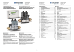
Gebrauchsanweisung EMS-System Küchensteuerung KCU Gasabsperreinrichtung FSA Luft-Druckwächter DW Edition 03.15 Operating Instructions EMS system Gebrauchsanweisung EMS-System Inhaltsverzeichnis Contents 1 Konformitätserklärung .......................... 2 1 Declaration of Conformity ..................... 2 2 Produkthaftung ..................................... 2 2 Product Liability .................................... 2 Kitchen Control Unit KCU Central Shut-off Device FSA Pressure Sensor DW Edition 03.15 2.1 2.2 2.3 2.4 Lieferumfang ................................................... 2 Bestimmungsgemäßer Gebrauch ................... 2 Gewährleistung ............................................... 2 Eingangskontrolle ........................................... 2 3 Einbau ................................................. 3 3 Installation ............................................ 3 4 Elektrischer Anschluss ......................... 5 4 Electrical Power Supply ........................ 5 5 6 Dichtheit prüfen .................................... 7 5 Inbetriebnahme .................................... 8 6 Tightness Test ...................................... 7 Commissioning ..................................... 8 7 Bedienung ............................................ 9 7 Operation ............................................. 9 8 Wartung ............................................... 9 8 Maintenance ......................................... 9 9 10 11 Störungshilfe ...................................... 11 9 Zubehör.............................................. 11 10 Technische Daten .............................. 12 11 Troubleshooting.................................. 11 Accessories ........................................ 11 Technical Data ................................... 12 3.1 3.2 3.3 3.4 4.1 4.2 4.2.1 4.3 4.4 6.1 6.2 6.3 7.1 7.2 7.3 8.1 WARNUNG Explosionsgefahr bei nicht sachgemäß ausgeführten Gasinstallationsarbeiten! Unsachgemäßer Einbau, Einstellung, Veränderung, Bedienung oder Wartung kann Verletzungen oder Sachschäden verursachen. Operating Instructions EMS system WARNING Explosion hazard if gas installation tasks are carried out improperly! Incorrect installation, adjustment, modification, operation or maintenance may cause injury or material damage. -1- Voraussetzungen ............................................ 3 Einbau KCU .................................................... 3 Einbau FSA ..................................................... 4 Einbau Luft-Druckwächter............................... 4 Leitungen auswählen ...................................... 5 Schaltplan KCU ............................................... 5 Elektrischer Anschluss KCU ........................... 6 Elektrischer Anschluss FSA ............................ 6 Elektrischer Anschluss Luft-Druckwächter ..... 7 2.1 2.2 2.3 2.4 3.1 3.2 3.3 3.4 4.1 4.2 4.2.1 4.3 4.4 Vorbereitende Arbeiten zur Inbetriebnahme... 8 6.1 Inbetriebnahme durchführen ........................... 8 6.2 Inbetriebnahmeprotokoll ................................. 8 6.3 FSA öffnen ...................................................... 9 7.1 Automatik-Betrieb ........................................... 9 7.2 Anlage schließen ............................................ 9 7.3 Vorgehensweise zur Funktionsprüfung ........ 10 8.1 Scope of Delivery ............................................2 Intended Use ...................................................2 Warranty ..........................................................2 User’s Inspection .............................................2 Requirements ..................................................3 Installation KCU ...............................................3 Installation of FSA ...........................................4 Installation of Pressure Sensor .......................4 Cable Selection ...............................................5 Wiring Diagram KCU .......................................5 Electrical Power Supply KCU ..........................6 Electrical Power Supply FSA ..........................6 Electrical Power Supply Pressure Sensor ...... 7 Preparatory Tasks for Commissioning ............ 8 Performing Commissioning .............................8 Commissioning Protocol .................................8 Open FSA ........................................................9 Automatic Operation .......................................9 Closing System ...............................................9 Functional Test Procedure ............................10 Gebrauchsanweisung EMS-System 1 Konformitätserklärung KCU Wir erklären als Hersteller, dass die Küchensteuerung KCU die grundlegenden Anforderungen folgender Richtlinien erfüllt: 90/396/EEC in Verbindung mit EN 13611, EN 13611-A1, EN 1643, 2006/95/EC in Verbindung mit den einschlägigen Normen, 2004/108/EG in Verbindung mit den einschlägigen Normen, 2009/142/EG in Verbindung mit den einschlägigen Normen. Operating Instructions EMS system 1 Gebrauchsanweisung EMS-System Declaration of Conformity 2 KCU We, the manufacturer, hereby declare that the kitchen control unit KCU complies with the essential requirements of the following Directives: 90/396/EEC in conjunction with EN 13611, EN 13611-A1, EN 1643, 2006/95/EC in conjunction with the relevant standards, 2004/108/EG in conjunction with the relevant standards, 2009/142/EG in conjunction with the relevant standards. 2.1 1 2 3 4 FSA Die Gasabsperrung FSA ist eine Kombination aus 2 GasMagnetventilen VAS. Wir erklären als Hersteller, dass das Gasmagnetventil VAS, gekennzeichnet mit der Produkt-ID-Nr. CE-0063BO1580 die grundlegenden Anforderungen folgender Richtlinien erfüllt: 90/396/EEC in Verbindung mit EN 161, EN 88, EN 126, EN 12067-1, EN 1854, 2006/95/EC in Verbindung mit den einschlägigen Normen, 2004/108/EG in Verbindung mit den einschlägigen Normen, 2009/142/EG in Verbindung mit den einschlägigen Normen. Produkthaftung Dieses Produkt trägt das CE-Zeichen. Es erfüllt die grundlegenden Anforderungen, die durch die Richtlinien der EG festgelegt worden sind. Wir sind der Hersteller dieses Produkts: Gastechnik Kirchner GmbH & Co. KG Gröninger Weg 7, D-74379 Ingersheim Phone +49 (0)7142 9191-30 Fax +49 (0)7142 9191-40 [email protected] www.gastechnik-kirchner.de FSA The kitchen safety valve FSA is a combination of 2 VAS gas solenoid valves. We, the manufacturer, hereby declare that the safety valve VAS, marked with product ID No. CE-0063BO1580 complies with the essential requirements of the following Directives: 90/396/EEC in conjunction with EN 161, EN 88, EN 126, EN 12067-1, EN 1854, 2006/95/EC in conjunction with the relevant standards, 2004/108/EG in conjunction with the relevant standards, 2009/142/EG in conjunction with the relevant standards. 2.2 2 Product Liability This product carries the CE-mark, which means that it satisfies the essential requirements laid down in the EC Directives. We are the manufacturer of this product: Gastechnik Kirchner GmbH & Co. KG Gröninger Weg 7, D-74379 Ingersheim Phone +49 (0)7142 9191-30 Fax +49 (0)7142 9191-40 [email protected] www.gastechnik-kirchner.de Lieferumfang 2.1 Küchensteuerung KCU 4 x M20-Verschraubung FSA bestehend aus: 1 2 3 − Doppel-Magnetventil VCS − Kugelhahn mit TAS Luft-Druckwächter DW Bestimmungsgemäßer Gebrauch Das Abgasabführung-Überwachungssystem EMS wird für gewerbliche Gasgeräte in der Gastronomie und Küche gemäß DVGW-Arbeitsblatt G 631 eingesetzt. Es überwacht die sichere Abführung der Küchenabgase. Das EMS-System besteht aus der Küchensteuerung KCU, der zentralen Absperreinrichtung FSA und dem Luft-Druckwächter DW zur automatischen Absperrung der Gaszufuhr bei unzureichender Abgasabführung. Für eine Übersicht über den Normalbetrieb siehe auch Kapitel 8.1 „Vorgehensweise zur Funktionsprüfung”, Seite 10. 4 2.2 Intended Use Scope of Delivery Kitchen control unit KCU 4 x M20 cable gland FSA comprising: − double solenoid VCS − ball valve with TAS Pressure sensor DW The EMS exhaust discharge monitoring system is used in industrial gas appliances in catering and kitchens in keeping with the DVGW instructional sheet G 631. It monitors an assured and safe discharge of exhaust from the kitchen. The EMS system consists of The Kitchen Control Unit KCU. The central shutoff device FSA. The DW pressure sensor for automatically shutting the supply of gas given an inadequate exhaust discharge. For an overview of normal operations, see section 8.1 “Functional Test Procedure”, page 10. 2.3 Gewährleistung 2.3 Warranty 2.4 Eingangskontrolle 2.4 User’s Inspection Es gelten unsere Allgemeinen Verkaufsbedingungen in der jeweils gültigen Fassung. Davon abweichende Vereinbarungen schränken die gesetzlichen Rechte des Käufers nicht ein. Eine darüber hinausgehende Garantie bedarf der vertraglichen Form und schließt Software-Updates, Verbrauchsartikel sowie Vandalismus an Bauteilen aus. Überprüfen Sie die Lieferung sofort nach Empfang auf Vollständigkeit und Unversehrtheit. Eventuelle Transportschäden sind unverzüglich zu melden. -2- Operating Instructions EMS system Our Standard Terms and Conditions of Sale effective at the time shall apply. Agreements diverging from these Standard Terms and Conditions do not restrict the legal rights of the buyer. Any warranty exceeding the above provisions shall require a contractual form and shall exclude componentrelated vandalism, software updates and consumables. Immediately upon receipt, the goods must be checked for completeness and potential damage in transit. Notice of any such damage must be given immediately. Gebrauchsanweisung EMS-System Operating Instructions EMS system 3 Einbau 3 Installation 3.1 Voraussetzungen 3.1 Requirements Gasarten Erdgas Flüssiggas (gasförmig) VORSICHT CAUTION The gas must be dry in all temperature conditions and must not contain condensate. Netzspannung, elektrische Leistungsaufnahme, Umgebungstemperatur, Schutzart, Eingangsdruck pe und Einbaulage siehe Typenschild. For mains voltage, electrical power consumption, ambient temperature, type of protection, inlet pressure pe and installation position, see type label. Do not exceed the maximum inlet pressure pe of 500 mbar. The pressure sensor may be damaged. KCU Nur in geerdeten Netzen einsetzen. KCU Only to be used in groundedneutral systems. FSA Öffnungszeit Schnell öffnend: ≤ 0,5 s Schließzeit Schnell schließend: < 1 s Der Eingangsdruck pe kann mit einem Mess-Stutzen abgegriffen werden, siehe Kapitel 10 „Zubehör”, Seite 11. VORSICHT Der Magnetantrieb wird beim Betrieb heiß. Oberflächentemperatur < 85 °C (185 °F) gemäß EN 60730-1 bei 10 % Überspannung und 25 °C (77 °F) Umgebungstemperatur. Ein bis 85 °C (185 °F) temperaturbeständiges Kabel verwenden. NOTICE Reinigungshinweise beachten! Beim Eindringen von Feuchtigkeit (z. B. bei Reinigung mit hohem Druck und/oder durch die Verwendung von Lösungsmitteln) können Beschädigungen am System nicht ausgeschlossen werden, ist ein entsprechender Schutz des Systems zwingend vorgeschrieben, liegt die Verantwortung für Schäden durch unsachgemäße Benutzung beim Betreiber. damage to the system cannot be ruled out, should protection of the system be compulsorily 3.2 3.2 Einbau KCU Die KCU wird vor oder in der Küche befestigt. Follow the cleaning instructions! Should moisture enter the system (e.g. on effecting high-pressure cleaning and/or by using solvents), prescribed, responsibility for damage due to incorrect use rests with the company operator. Installation KCU Mount KCU in front of or inside the kitchen. Einbaulage Waagerecht KCU erschütterungsfrei montieren Gehäuse eben (mechanisch spannungsfrei) anschrauben Empfohlene Montagehöhe: ca. 1,6 – 1,8 m CAUTION Max. Eingangsdruck pe 500 mbar nicht überschreiten. Andernfalls kann das Ventil zerstört werden. Operating Instructions EMS system HINWEIS Types of gas Natural gas LPG (gaseous) Das Gas muss unter allen Temperaturbedingungen trocken sein und darf nicht kondensieren. VORSICHT Gebrauchsanweisung EMS-System Fitting position Horizontal Install KCU in a location not subject to vibration Housing must be fitted free of mechanical stress Recommended installation height: approx. 1.6–1.8 m Deckel vor Verdrahtung demontieren! 1 FSA Opening time Fast opening: ≤ 0.5 s Closing time Fast closing: < 1 s The inlet pressure pe can be measured using a pressure test point, see section 10 “Accessories”, page 11. Remove cover before wiring! 2 3 116 CAUTION The solenoid actuator heats up during operation. Surface temperature < 85°C (185°F) acc. to EN 60730-1 at an overvoltage of 10% and an ambient temperature of 25°C (77°F). Use a heat-resistant cable rated at 85°C (185°F). -3- Gebrauchsanweisung EMS-System Operating Instructions EMS system HINWEIS Schritte 1 bis 7 wie gezeigt durchführen NOTICE Für die Kabeldurchführungen die mitgelieferten Verschraubungen M16 verwenden, um Schutzart IP 54 zu erhalten. Für die Montage des Gehäuse-Unterteils empfehlen wir Befestigungsschrauben ø 3,5 x 25 mm. 1 Gebrauchsanweisung EMS-System Operating Instructions EMS system Perform steps 1 to 7 as illustrated HINWEIS For the cable leadthroughs: Use M16 cable glands delivered with the unit to obtain enclosure IP 54. FSA nicht an den Magnetspulen festhalten, sondern am Ventilkörper! Retaining screws ø 3.5 x 25 mm are recommended to mount the lower section of the housing. 3 2 CAUTION Do not hold FSA by the solenoids but on the valve body! 3.3 Einbau FSA Die FSA sollte idealerweise außerhalb der Küche (z. B. im Technikraum oder Versorgungskeller) installiert werden. Wird die FSA in der Küche montiert, muss darauf geachtet werden, dass sie nicht mit Reinigungsmitteln in Berührung kommt! Siehe auch Kapitel 3.1 „Voraussetzungen”, Seite 3. Einbaulage Schwarzer Magnetantrieb senkrecht stehend bis waagerecht liegend. Nicht über Kopf! Der Mindestabstand zu Mauerwerk oder umgebenden Gehäusen muss mindestens 20 mm betragen. Dichtmaterial und Späne dürfen nicht in das Ventilgehäuse und auf die Dichtflächen gelangen. Auf genügend Freiraum für die Montage achten. HINWEIS Um die FSA schmutzfrei zu halten, wird empfohlen, vor der Anlage einen Filter (50 µm) einzubauen. VORSICHT FSA nicht in einen Schraubstock einspannen. Nur am Achtkant des Flansches mit passendem Schraubenschlüssel gegenhalten. Bei Beschädigung des Gehäuses besteht die Gefahr von äußerer Undichtheit. 3.3 3.4 Einbau Luft-Druckwächter Druckabgriff des Luft-Druckwächters an einem 3.4 Installation of Pressure Sensor Fit the pressure sensor pressure tap at a flow- Ideal sind Punkte nahe der Ablufthaube bzw. am The ideal spots are near the used air hood and/or at strömungstechnisch günstigen Ort installieren. Installation of FSA Ideally the FSA is not to be installed in the kitchen (but e.g. in the equipment room or supplies basement). It must be ensured that the FSA does not come into contact with cleaning agents if it is fitted in the kitchen! Abluftkanal möglichst nahe am Lüftungsmotor (5). − Nur so wird eine optimale Erfassung des Unterdrucks erreicht. See section 3.1 “Requirements”, page 3. VORSICHT Fitting position Black solenoid actuator in the vertical position or tilted up to the horizontal. Not upside down! The FSA must be at least 20 mm away from the masonry or surrounding housings. Sealing material and thread cuttings must not be allowed to get into the valve housing and the sealing surfaces. Ensure that there is sufficient space for installation. Empfohlene Einbaulage: mit senkrecht stehender Membrane! Bei anderer Einbaulage kann es in Kombination mit einem zu geringen Unterdruck der Ablufthaube zu Fehlschaltungen bzw. Störungen der Gaszufuhr kommen. Bei Inbetriebnahme Schaltpunkt prüfen. NOTICE favorable location. the used air duct preferably next to the ventilation motor (5). − Only in this way the negative pressure is optimally registered. CAUTION Recommended mounting position: with membrane in the vertical plane! With any other mounting position, this combined with too low vacuum in the used air hood can lead to switching errors or malfunctions in the gas feed. Check the switching point on commissioning. To keep the FSA free of dirt, we recommend that a filter (50 µm) be installed upstream of the system. Einbau Die Schlauchanschlüsse (1) sind senkrecht nach unten gerichtet. Den Impulsanschlussschlauch (2) wegen der Möglichkeit von Kondensatbildung mit Gefälle zur Anschlussstelle am Lüftungskanal verlegen. Nur bei senkrecht stehender Membrane entspricht der Schaltdruck ps dem Skalenwert SK. Anschlüsse vor dem Eindringen von Schmutz oder Feuchtigkeit aus dem zu messenden Medium und aus der Umgebungsluft schützen. Befestigung mit Halteclip oder Haltewinkel (3). CAUTION Do not clamp the FSA in a vice. Only secure the flange by holding the octagon with a suitable spanner. In case of a damaged housing there is a risk of external leakage. -4- Installation The hose connections (1) are directed vertically downwards. Given the possibility of condensate forming, incline the pulse connection hose (2) to the connection point at the ventilation duct. Only with a vertical membrane does the ps switching pressure comply with the SK scale value. Protect connections from dirt or moisture entering from the medium to be tested and from the ambient air. Secure with retaining clip or retaining bracket (3). Gebrauchsanweisung EMS-System Operating Instructions EMS system Wird der Luft-Druckwächter ohne Halteclip ange- schraubt, maximal 2 Schrauben verwenden, um Verspannungen vorzubeugen. Einstellbereich: 0,2 – 3 mbar Der Schaltpunkt wird mit dem Handrad (6) eingestellt. Dazu die niedrigste Lüftungsstufe wählen und mit einem Durchgangsprüfer an den Kontakten 15 bis 17 den genauen Schaltpunkt bestimmen. Wenn der Drückwächter korrekt schaltet, ist ein Klicken zu hören. If the pressure sensor is screwed on without any 4.2 retaining clip, then use a maximum 2 screws to prevent any warping Setting range: 0.2–3 mbar The hand dial (6) is for setting the switching point. For this, select the lowest ventilation step and – using a continuity tester – determine the precise switching point at contacts 15 to 17. A click can be heard when the pressure sensor is correctly in operation. Aufbau und Montage des Schlauchsets 2 Impulsschlauch Ø 7 mm, L = 1,9 m 4 Winkelstutzen (dem Luftstrom entgegengerichtet montiert) 7 Schlauchanschlussflansch (Kanalbohrung Ø 12 mm) 8 Anschlussrohr Schaltplan KCU Operating Instructions EMS system 4.2 Wiring Diagram KCU Setup and assembly of the hose set 2 Pulse hose Ø 7 mm, L = 1.9 m 4 Angle stub (mounted against the flow of air) 7 Hose connection (duct drill hole Ø 12 mm) 8 Connection pipe 4 Elektrischer Anschluss Anlage spannungsfrei schalten Gaszufuhr absperren Verdrahtung nach EN 60204-1 4 Electrical Power Supply Disconnect system from electrical power supply Shut off the gas supply Wiring to EN 60204-1 4.1 4.1 Leitungen auswählen KCU Betriebsbedingtes Netzkabel und Sicherungen gemäß örtlichen Vorschriften verwenden. Gebrauchsanweisung EMS-System Cable Selection KCU FSA Ein bis 85 °C (185 °F) temperaturbeständiges Kabel verwenden. KCU Use mains cable and fuses suitable for the type of operation and compiling with local regulations. FSA U FSA Use a heat-resistant cable rated at 85°C (185°F). DW KCU Zuleitung 3 x max. 1,5 mm2 KCU lead 3 x max. 1.5 mm2 KCU zu FSA (V1 und V2) 2 3 x max. 1,5 mm KCU to FSA (V1 and V2) 2 3 x max. 1.5 mm KCU zu Lüftungssteuerung (Anforderung 1 oder 2) 2 3 x max. 1,5 mm KCU to ventilation control (Requirement 1 or 2) 2 3 x max. 1.5 mm KCU zu Luft-Druckwächter 2 Luft-Druckwächter 4 x max. 1,5 mm KCU to pressure sensor 2 Pressure sensor 4 x max. 1.5 mm LED Nur wenn vorhanden Only if fitted NTA KCU zu Gebäudeleittechnik Betriebsmeldung 3 x max. 1,5 mm2 KCU to building control system Operation message 3 x max. 1.5 mm2 mC KCU zu Not-Aus-Taster 2 3 x max. 1,5 mm KCU emergency stop switch 2 3 x max. 1.5 mm DIP B F BR Gasabsperreinrichtung FSA, Gasventil V1/V2 im Einzelventil VCS Gas shut-off FSA, gas valve V1/V2 in the individual valve VCS Fremdspannung (24 – 400 VAC/DC) aus Abluftsteuerung (Anforderung 2), falls kein potentialfreier Kontakt (Anforderung 1) vorhanden ist. External voltage (24–400 VAC/DC) from exhaust control (Requirement 2) if there is no dry contact (Requirement 1) present. Luft-Druckwächter zur Überwachung der Abluftsteuerung Pressure sensor for monitoring the exhaust control Konfigurationsschalter für B/DW Configuration switch for B/DW Konfigurierbares, potentialfreies Melderelais Configurable, floating transmitting relay Sicherung: 5 x 20 mm, 250 V / 1 A, mittelträge Fuse: 5 x 20 mm, 250 V/1 A, medium time-lag LED-Anzeige zur optischen Visualisierung LED display for optical visualization Not-Aus-Taster: potentialfreier Öffner! Emergency Stop switch: floating break contact! Micro-Controller U DW V1/V2 intern gebrückt in der FSA V1/V2 internally bridged in the FSA Hinweis: Um auf die Platine zuzugreifen, Schrauben lösen und Frontseite abheben. Siehe auch Kapitel 3.2 „Einbau KCU”, Seite 3. -5- V1/V2 Note: To access the PCB, undo the screws and lift off the front. See section 3.2 “Installation KCU”, page 3. Gebrauchsanweisung EMS-System 4.2.1 Elektrischer Anschluss KCU Der elektrische Anschluss der KCU erfolgt über die entsprechenden Federzugklemmen auf der Steuerplatine. Es können Drähte mit einem maximalen Querschnitt von 1,5 mm2 verklemmt werden. Auf korrekten Anschluss nach Plan ist zu achten, da ansonsten das Gerät beschädigt werden kann. Operating Instructions EMS system Gebrauchsanweisung EMS-System Über die Klemme 18, 19 und 20 stellt die KCU 4.2.1 Electrical Power Supply KCU entweder eine Störmeldung oder eine Betriebsmeldung bereit. Die Konfiguration der Meldung erfolgt über den DIP-Schalter 4. ON: Störmeldeausgang, OFF: Betriebsmeldung Ventil. The electrical connection of the KCU is via the corresponding spring terminals on the control board. It can be clamped wires with a maximum cross section of 1.5 mm2. It is important to ensure that the connection is made according to plan otherwise the device may be damaged. Der Anschluss der Zuleitung erfolgt über die The connection of the lead are connected via Klemmen 1 – 3. terminals 1–3. Ein externer Not-Aus-Taster wird an den An external emergency stop switch is connected Klemmen 4 – 5 angeschlossen. to terminals 4–5. Wird kein Not-Aus-Taster verwendet, müssen die If no emergency stop switch is used, the terminals 4 Klemmen 4 und 5 gebrückt werden. and 5 must be bridged. Die FSA wird an den Klemmen 7 – 9 angeschlossen. The FSA is connected to the terminals 7–9. Either the Requirement 1 or Requirement 2 Die Einschaltüberwachung der Lüftungsanlage erfolgt über die Anschlüsse Anforderung 1 oder connection monitors ventilation unit switch-on. Constructional conditions determine which of the Anforderung 2. Welcher der beiden Anschlüsse two connections is used. genutzt wird, hängt von den baulichen Gegebenheiten ab. − Requirement 1: The used air hood has a dry − Anforderung 1: Die Ablufthaube besitzt einen potentialfreien Kontakt. Dieser überbrückt die Klemmen 13 und 14, wenn die Haube eingeschaltet ist. HINWEIS Fremdspannung auf den Klemmen 13 und 14 kann zu Zerstörung der KCU führen! − Anforderung 2: Die Ablufthaube besitzt keinen potentialfreien Kontakt. An den Klemmen 10 und 11 kann in diesem Fall eine Fremdspannung (24 – 400 V AC / DC) angelegt werden, die zusammen mit der Haube eingeschaltet wird. − Hierzu kann z. B. die Spulenspannung des Hauptschützes des Lüftungsmotors oder die Melde-/Kontrollleuchte verwendet werden. HINWEIS HINWEIS contact. It bridges terminals 13 and 14 when the hood is switched on. NOTICE External voltage on terminals 13 and 14 can destroy the KCU! Via terminal 18, 19 and 20, the KCU provides either a fault or an operation signal. The configuration of the signal is via the DIP switch 4. ON: fault signal output, OFF: operation signal valve. Configuration DIP-switch NOTICE Stellung bei DIP 1 und DIP 2 muss auf OFF stehen. DIP 1 and DIP 2 must be set to OFF. DIP 1: keine Funktion DIP 2: keine Funktion DIP 3: ON: Wechselkontakt OFF: Schließkontakt DIP 4: ON: Störmeldung OFF: Betriebsmeldung DIP 1: no function DIP 2: no function DIP 3: ON: changeover contact OFF: normally open (NO) contact DIP 4: ON: fault signal OFF: operation signal Auslieferzustand DIP 1 – 4: Klemme 4 und 5: Klemme 10 und 11: Settings at delivery DIP 1–4: OFF Terminal 4 and 5: bridged Terminal 10 and 11: bridged OFF gebrückt gebrückt Zusammenbau Um den Deckel anzuschrauben, die vier Schrauben mit einem Kreuzschlitzschraubendreher anziehen. Assembly To fasten the cover tighten the four screws with a Phillips screwdriver. 4.3 4.3 − Requirement 2: The used air hood has no dry contact. In this case an external voltage (24–400 V AC/DC) – switched on together with the hood – can be applied to terminals 10 and 11. − Use can be made here, for instance, of the coil voltage of the ventilation motor main contactor or the signaling/pilot light. NOTICE Die Fremdspannung darf nicht direkt über die Motorenzuleitung abgegriffen werden! The external voltage must not be tapped directly via the motor supply lead! Zur Überwachung der Abluftleistung wird der Luft- For exhaust power monitoring connect the pressure Druckwächter an der KCU angeschlossen. Der Anschluss erfolgt auf den Klemmen 15, 16 und 17. Wird ein Druckschalter mit lediglich einem Schließer anstatt einem Wechselkontakt verwendet, erfolgt der Anschluss auf den Klemmen 15 und 16. Der DIPSchalter 3 muss dann auf OFF gestellt werden. Konfiguration DIP-Schalter Operating Instructions EMS system Elektrischer Anschluss FSA Anschlüsse FSA 1 = N 2 = LV1/V2 (intern gebrückt) 3 = nicht belegt sensor on the KCU. The connections are on terminals 15, 16 and 17. If a pressure switch with only one normally open contact is used instead of a changeover contact, the connection is via terminals 15 and 16. Then the DIP switch 3 must be set to OFF. = PE -6- Electrical Power Supply FSA FSA connections 1 = N 2 = LV1/V2 (internally bridged) 3 = not assigned = PE Gebrauchsanweisung EMS-System Operating Instructions EMS system Schritte 1 bis 8 wie gezeigt durchführen Gebrauchsanweisung EMS-System Perform steps 1 to 8 as illustrated 5 Operating Instructions EMS system Dichtheit prüfen 5 CAUTION VORSICHT Übersicht Schaltung Circuit Overview Max. Eingangsdruck pe 500 mbar nicht überschreiten. Do not exceed the maximum inlet pressure pe of 500 mbar. Zur Dichtheitsprüfung gemäß DVGW Regelwerk Arbeitsblatt G 600 empfehlen wir, Stickstoff über einen separaten MessStutzen zuzuführen – siehe Kapitel 10 „Zubehör”, Seite 11. Max. zulässiger Druck: pe max = 500 mbar To be able to check the tightness according to DVGW Code of Practice G 600 we recommend supplying nitrogen via a separate pressure test point – see section 10 “Accessories”, page 11. Max. allowable pressure: pe max = 500 mbar Voraussetzungen Requirements Disconnect the system from the electrical power supply. Shut off the gas supply. Anlage ist spannungsfrei geschaltet. Gaszufuhr ist abgesperrt. PE LV2 N LV1 Anschlüsse für Mess-Stutzen 3 1 2 (1) Vordruckseitig (2) + (3) Mitteldruckseitig Connections for measuring sockets (4) Hinterdruckseitig Rohrleitungen undicht 4.4 Elektrischer Anschluss Luft-Druckwächter Abdeckhaube des Luft-Druckwächters demontieren 4.4 Dichtung am Ventil bzw. am Rohrleitungssystem überprüfen. FSA undicht FSA demontieren und an den Hersteller schicken. Electrical Power Supply Pressure Sensor 1 (1) Admission pressure side HINWEIS Mount the hood. -7- (2) + (3) Medium pressure side (4) Back pressure side Piping not seal-tight 2 Inspect seal at the valve or at the piping system. FSA not seal-tight Dismantle FSA and send to the manufacturer. Dismantle the pressure sensor hood Hinterdruckseitige Rohrleitung: Vor Inbetriebnahme Prüfdruck ablassen. Abdeckhaube montieren. Tightness Test NOTICE Back pressure side pipe: Release test pressure before commissioning. Gebrauchsanweisung EMS-System 6 Inbetriebnahme HINWEIS Bei der Inbetriebnahme ist die ordnungsgemäße Ausführung und einwandfreie Funktion der Überwachung der sicheren Abgasführung nach DVGW Arbeitsblatt G 631, Abschnitt 5.2.7.3 durch das Vertragsinstallationsunternehmen zu überprüfen und dies zu dokumentieren. Operating Instructions EMS system 6 Commissioning NOTICE Commissioning may only be carried out by authorized fitters/personnel. The unit may only be released for unsupervised operation once commissioning has been completed correctly. 6.1 6.1 Sicherstellen, dass alle Verbraucher (z. B. Herd), angeschlossen und darauf befindliche EntnahmeStellen geschlossen sind. Kugelhahn (Absperrung) oder vorgeschaltetes Ventil öffnen. KCU mit Netzspannung versorgen. − Alle LED leuchten einmal auf (LED-Test). Preparatory Tasks for Commissioning 6.2 6.2 Inbetriebnahme durchführen HINWEIS Performing Commissioning NOTICE Alle Verbraucher hinter der FSA müssen geschlossen sein. All consumers downstream of the FSA must be closed. KCU einschalten − Falls ein Not-Aus-Taster angeschlossen und Switch on KCU − A connected and interlocked emergency stop verriegelt ist, muss dieser zuerst entriegelt werden: rote LED erlischt. switch must firstly be unlocked: red LED is extinguished. − Ablufthaube einschalten, um Anforderung 1 − Switch on used air hood to generate − Luft-Druckwächter meldet korrekte Abgas- − Pressure sensor signals correct exhaust − FSA öffnet: grüne LED leuchtet. − FSA opens: green LED is on. oder 2 zu generieren: blaue LED leuchtet. abführung: gelbe LED leuchtet. Lüftung ausschalten. − FSA schließt und ist für 60 s verriegelt: Weiße LED blinkt erst und leuchtet dann. 6.3 6.3 Inbetriebnahmeprotokoll Eingestellter Differenzdruck (mbar)/ Operating pressure (mbar) − The white LED flashes for 60 s. After the 60 s are over: − White LED is on. − KCU is ready. For proper operations, the pressure sensor is to be set to ensure safe discharge of the exhaust under all operating conditions! See section 3.4 “Installation of Pressure Sensor”, page 4. Gasart/ Type of gas extraction points fitted to the consumers must be closed. Open the ball valve (locking) or open the upstream valve. Supply KCU with mains power. − All LED flash once (LED test). Nach Ablauf der 60 s: − Weiße LED leuchtet. − KCU ist betriebsbereit. Für den ordnungsgemäßen Betrieb ist der Luft-Druckwächter so einzustellen, dass ein sicheres Abführen des Abgases in allen Betriebszuständen gewährleitet ist! Siehe Kapitel 3.4 „Einbau Luft-Druckwächter”, Seite 4. Inbetriebnahme vom/ Commissioning date All consumers, e.g. stove, must be connected. All − Die weiße LED blinkt für 60 s. NOTICE Hier können die Daten der Inbetriebnahme vom Installateur/Fachkundigen eingetragen werden. CAUTION Die Inbetriebnahme darf nur der befugte Installateur durchführen. Erst nach korrekt durchgeführter Inbetriebnahme darf das Gerät für den unbeaufsichtigten Betrieb freigegeben werden. Operating Instructions EMS system HINWEIS When commissioning the proper execution and proper function of the monitoring of safe exhaust system according to DVGW G 631 section 5.2.7.3 should be checked by the installation contractor and to document it. VORSICHT Vorbereitende Arbeiten zur Inbetriebnahme Gebrauchsanweisung EMS-System Requirement 1 or 2: blue LED is on. discharge: yellow LED is on. Switch off ventilation. − FSA closes and is interlocked for 60 s: White LED firstly flashes and is then on. -8- Commissioning Protocol The commissioning data can be entered by the fitter/authorized personnel here. KCU Seriennummer/ KCU serial number Raum/ Room Eingangsdruck pe (mbar)/ Inlet pressure pe (mbar) Funktionsprüfung in Ordnung Functional test is OK Gebrauchsanweisung EMS-System 7 7.1 Bedienung FSA öffnen Kugelhahn vor der FSA öffnen. Operating Instructions EMS system 7 7.1 Gebrauchsanweisung EMS-System Operation Open FSA HINWEIS Open ball valve upstream of the FSA. HINWEIS NOTICE Alle Verbraucher müssen geschlossen sein. All consumers must be closed. 7.2 Automatik-Betrieb Spannungsversorgung der KCU sicherstellen Not-Aus-Taster muss entriegelt sein: − Weiße LED leuchtet − KCU ist betriebsbereit Lüftung einschalten 7.2 Automatic Operation Ensure power supply to the KCU Emergency stop switch must be unlocked: − White LED is on − KCU is ready to be operated Switch on ventilation ist aktiv). Wartung HINWEIS Nach einer Abgaswegüberprüfung (nach Kehr- und Überprüfungsordnung) oder nach Funktionsprüfungen der Küchenlüftungsanlage sind KCU, FSA und LuftDruckwächter auf ihre Funktionstüchtigkeit hin zu untersuchen! Siehe auch Kapitel 6 „Inbetriebnahme”, Seite 8. Um einen störungsfreien Betrieb zu gewährleisten, jährlich die Dichtheit und Funktion der FSA überprüfen. Siehe Kapitel 5 „Dichtheit prüfen”, Seite 7. Siehe auch Technische Regel Gasinstallation DVGW Arbeitsblatt G 631, Abschnitt 5.2.7.3. In order to ensure smooth operation, check the tightness and function of the FSA every year. See section 5 “Tightness Test”, page 7. See also Technical rule gas installation DVGW G 631, section 5.2.7.3. Sieb reinigen Cleaning the strainer Durchflussmenge prüfen. Checking the flow rate. Schritte 1 bis 11 wie gezeigt durchführen See section 5 “Tightness Test”, page 7. Flow rate has lessened: − Clean strainer. Note: The valves & fittings are only to be removed from the pipe and re-fitted at the inlet and outlet flange. Perform steps 1 to 11 as indicated 3 7.3 Closing System Switch off ventilation. Requirement (1 or 2) is extinguished. KCU closes FSA: − The blue, yellow and green LEDs are off − White LED flashes for 60 s 1 2 4 5 6 7 8 (restart lockout is active). − Weiße LED leuchtet (betriebsbereit). 8 NOTICE Siehe Kapitel 5 „Dichtheit prüfen”, Seite 7. Durchflussmenge hat sich verringert: − Sieb reinigen. Hinweis: Die Armaturen dürfen nur am Ein- und Ausgangsflansch aus der Rohrleitung aus- und wieder eingebaut werden. Anforderung 1 oder 2 an KCU wird generiert: Either Requirement 1 or 2 for KCU is generated: Blaue LED leuchtet Blue LED is on Bei korrekter Abgasabführung schaltet der LuftThe pressure sensor is actuated given correct Druckwächter: suction power: Weiße LED erlischt, gelbe LED leuchtet White LED is extinguished, yellow LED is on KCU schaltet FSA ein: KCU switches on FSA: Grüne LED leuchtet Green LED is on Die Gasversorgung ist freigegeben: Clearance is given for the gas supply: Blaue, gelbe und grüne LED leuchten. Der Gasherd The blue, yellow and green LEDs light up. The gas kann bedient werden. cooker can be operated. Ein Betätigen des Not-Aus-Tasters oder ein Abschal- Actuating the emergency stop switch or switching ten der Lüftung führt zum Abschalten der FSA durch off the ventilation results in the KCU shutting down die KCU. the FSA. 7.3 Anlage schließen Lüftung ausschalten. Anforderung (1 oder 2) erlischt. KCU schließt FSA: − Blaue, gelbe und grüne LED erlöschen − Weiße LED blinkt für 60 s (Wiedereinschaltsperre Operating Instructions EMS system − White LED is on (ready for operation). 8 9 Maintenance 10 NOTICE KCU, FSA and pressure sensor are to be examined as to their working order after an exhaust path examination (according to the clean sweeping and inspection ordinance) or after functional checks undertaken on the kitchen ventilation system! See section 6 “Commissioning”, page 8. -9- 11 Gebrauchsanweisung EMS-System 8.1 8.1 Gebrauchsanweisung EMS-System Operating Instructions EMS system Vorgehensweise zur Funktionsprüfung Functional Test Procedure Operating Instructions EMS system Folgende Vorgehensweisen zur Funktionsprüfung der Überwachung der Abgasführung gem. DVGW-Arbeitsblatt G 631 sind nach Abstimmung zwischen der Hauptgeschäftsführung des Deutschen Vereins des Gas- und Wasserfaches (DVGW) in Bonn und dem Bundesverband des Schornsteinfegerhandwerks (Zentralinnungsverband – ZIV) abgesprochen: Störungssimulation Druckwächter Störungssimulation Haube z. B. durch: Druckabgriff in Haube verschließen PVC-Schlauch an Druckwächter abziehen Schaltpunkt an Druckwächter über Schaltrad nach oben verändern Signalleitung von Steuerung zu Druckwächter unterbrechen Signalleitung von Druckwächter zu Steuerung unterbrechen z. B. durch: Haube ausschalten Sicherung der Haube unterbrechen Abluftstrom unterbrechen - 10 - Gebrauchsanweisung EMS-System 9 Störungshilfe Bei einer Störung der Anlage schließt die KCU die FSA automatisch. Weiße LED leuchtet nicht / blinkt nicht Es liegt keine Versorgungsspannung an − Versorgungsspannung auf Klemme 1 – 3 überprüfen. − Sicherung auf Platine überprüfen. Wenn Sicherung defekt, Sicherung ersetzen. Siehe auch Kapitel 4.2 „Schaltplan KCU”, Seite 5. Sicherung in Ordnung: − Gerät an den Hersteller senden. Rote LED leuchtet Not-Aus-Taster zurücksetzen. Wenn kein Not-Aus-Taster angeschlossen ist: − Klemme 4 und 5 brücken Wenn beide Abhilfemöglichkeiten nicht zum Erlöschen der roten LED führen, besteht ein interner Fehler − Gerät an den Hersteller senden. Blaue LED leuchtet nicht Ablufthaube nicht in Betrieb − Keine Anforderung 1 (potentialfrei) auf Klemme 13 und 14 oder − Keine Anforderung 2 (Fremdspannung) auf 9 Replace the fuse if defective. See section 4.2 “Wiring Diagram KCU”, page 5. Fuse OK: − Send device to the manufacturer. Red LED is on Re-set emergency stop switch. If no emergency stop switch is connected: − Über Handrad Schaltpunkt neu einstellen. Siehe auch Kapitel 3.4 „Einbau LuftDruckwächter”, Seite 4 Störung Lüftung, fehlende/unzureichende Absaugung − Druck hat sich geändert − Über Handrad Schaltpunkt neu einstellen. PVC-Schlauch bzw. Druckabgriff ist verschmutzt (z. B. durch Öl, Fett, Kondensat) − PVC-Schlauch/Druckabgriff reinigen Schaltkontakte im Luft-Druckwächter sind verschmutzt oder korrodiert. − Schaltkontakte reinigen. öffnet, ist die FSA defekt. − Ohmschen Durchgang prüfen − FSA austauschen − Defekte FSA an Hersteller senden − Bridge terminals 4 and 5 An internal fault is present should the two corrective actions not lead to the red LED being extinguished Wiedereinschaltsperre aktiv (60 s) − Weiße LED blinkt − Ende der Einschaltsperre abwarten − Send device to the manufacturer. Blue LED is off Used air hood not in operation 10 − No Requirement 1 (floating) on terminals 13 Zubehör MessStutzen Um das Rohrleitungssystem vor der Gasabsperreinrichtung FSA kontrolliert zu entlüften, kann ein Mess-Stutzen im Eingang des ersten Ventils V1 der FSA eingebaut werden. Über den Mess-Stutzen kann mit Hilfe eines Druckmessgerätes der Eingangsdruck pe angezeigt werden. Um die äußere Dichtheit prüfen zu können, wird über den MessStutzen Stickstoff zugeführt. Anlage spannungsfrei schalten. Gaszufuhr absperren. and 14 or − No Requirement 2 (external voltage) on terminals 10 and 11 Gelbe LED leuchtet nicht Luft-Druckwächter falsch angeschlossen (Öffner und Schließer vertauscht) eingestellt Weiße LED leuchtet − Ja: nächste Frage − Nein: siehe entsprechende Fehlerbeschreibung Blaue LED leuchtet − Ja: nächste Frage − Nein: siehe entsprechende Fehlerbeschreibung Gelbe LED leuchtet − Ja: nächste Frage − Nein: siehe entsprechende Fehlerbeschreibung Wenn diese 3 LED leuchten, die FSA jedoch nicht − Examine fuse on the PCB. Yellow LED is off Pressure sensor incorrectly connected (break and open contacts mixed up) Kapitel 4.2.1 „Konfiguration DIP-Schalter”, Seite 6 − Nein: nächste Frage − Ja: siehe entsprechende Fehlerbeschreibung White LED is off/does not flash No distribution voltage is on hand − Check the distribution voltage on terminals 1–3. Operate Requirement 1 or 2. See section 4.2.1 Schaltpunkt des Luft-Druckwächters falsch FSA öffnet nicht Rote LED leuchtet Troubleshooting If malfunction occurs, the KCU closes the FSA automatically. Klemme 10 und 11 Anforderung 1 oder 2 bedienen. Siehe auch Kapitel 4.2.1 „Elektrischer Anschluss KCU”, Seite 6. − Luft-Druckwächter korrekt anschließen Luft-Druckwächter hat nur Schließer − DIP-Schalter 3 auf OFF stellen, siehe auch Gebrauchsanweisung EMS-System Operating Instructions EMS system “Electrical Power Supply KCU”, page 6. − Correctly connect the pressure sensor Pressure sensor only has an open contact − Set DIP switch 3 to OFF See section 4.2.1 “DIP switch configuration”, page 6 Pressure sensor switching point incorrectly set − Re-set switching point using the hand dial See section 3.4 “Installation of Pressure Sensor”, page 4 Ventilation fault, lack of/inadequate suctioning − Pressure has changed − Re-set switching point using the hand dial PVC hose and/or pressure tap is contaminated (e.g. from oil, grease, condensate) − Clean PVC hose/pressure tap Switching contacts in the pressure sensor are dirty or corroded. − Clean the switching contacts. - 11 - Operating Instructions EMS system FSA does not open Red LED is on − Negative: next question − Affirmative: see corresponding fault description White LED is on − Affirmative: next question − Negative: see corresponding fault description Blue LED is on − Affirmative: next question − Negative: see corresponding fault description Yellow LED is on − Affirmative: next question − Negative: see corresponding fault description The FSA is defective should these 3 LEDs be on yet the FSA does not open. − Check ohmic continuity − Replace FSA − Send defective FSA to the manufacturer Restart lockout active (60 s) − White LED flashes − Wait for end of switch-on lockout 10 Accessories Pressure test points To vent the piping system up stream of the laboratory safety valve FSA in a controlled way, a pressure test point can be installed at the inlet of the first valve V1 of the FSA. The inlet pressure pe can be displayed with a pressure gauge connected to this pressure test point. In order to be able to check the external tightness, nitrogen is supplied via the pressure test point. Disconnect the system from the electrical power supply. Shut off the gas supply. Gebrauchsanweisung EMS-System 11 Technische Daten KCU Netzspannung: 230 V AC, 50/60 Hz Schutzklasse: 1 Leistungsaufnahme: ca. 120 VA Umgebungstemperatur: 0 – 60 °C Schutzart: IP 54 Gehäusefarbe: RAL 7035 lichtgrau Maße (L x H x B): 200 x 120 x 60 mm Konfigurierbares potenzialfreies Melderelais: max. 0,1 A, 230 V AC Ventilausgang: max. Strom: 500 mA Spannung: 230 V AC LED-Anzeige: für Status und Störung FSA Gasarten: Erdgas, Flüssiggas (gasförmig) und Luft. Das Gas muss unter allen Temperaturbedingungen trocken sein und darf nicht kondensieren. Eingangsdruck pe max.: 500 mbar Umgebungstemperatur: 0 – 40 °C, keine Betauung zulässig Netzspannung 230 V AC, +10/-15 %, 50/60 Hz 120 V AC, +10/-15 %, 50/60 Hz Leistungsaufnahme: 70 W Öffnungszeit Schnell öffnend: ≤ 0,5 s Schließzeit Schnell schließend: < 1 s Sicherheitsventil: Klasse A, Gruppe 2 nach EN 13611 und EN 161 Elektrischer Anschluss Stecker mit Steckdose nach EN 175301-803 Schutzart: IP 54 Einschaltdauer: 100 % Leistungsfaktor der Magnetspule: cos φ = 1 Schalthäufigkeit: beliebig Ventilgehäuse: Aluminium Ventildichtung: NBR Anschlussverschraubung mit Innengewinde: Rp nach ISO 7-1 Gebrauchsanweisung EMS-System Operating Instructions EMS system 11 Technical Data KCU Mains voltage: 230 V AC, 50/60 Hz Safety class: 1 Power consumption: approx. 120 VA Ambient temperature: 0–60°C Enclosure: IP 54 Housing color: RAL 7035 light grey Dimensions (L x H x B): 200 x 120 x 60 mm Configurable potential-free transmitting relay: max. 0.1 A, 230 V AC Valve output: 500 mA Voltage: 230 V AC LED display: for status and faults FSA Types of gas: natural gas, LPG (gaseous) and air. The gas must be dry in all temperature conditions and must not contain condensate. Inlet pressure pe max.: 500 mbar Ambient temperature: 0–40°C, no condensation permitted Mains voltage 230 V AC, +10/-15%, 50/60 Hz 120 V AC, +10/-15%, 50/60 Hz Power consumption: 70 W Opening time Quick opening: ≤ 0.5 s Closing time Quick closing: < 1 s Safety valve: Class A, group 2 to EN 13611 and EN 161 Electrical connection Plug with socket to EN 175301-803 Enclosure: IP 54 Duty cycle: 100% Power factor of the solenoid coil: cos φ = 1 Switching frequency: any Valve housing: aluminum Valve seal: NBR Connection flange with internal thread: Rp to ISO 7-1 Operating Instructions EMS system DW Netzspannung: 24 – 240 V AC, 50/60 Hz Schutzklasse: 2 Kontaktbelastung: I = 5 A bei cos φ = 1 I = 0,5 A bei cos φ = 0,6 Schutzart: IP 54 Maße (L x H x B): 107 x 107 x 80 mm Einstellbereich: 0,2 – 3 mbar Schaltdifferenz: 10 – 16 Pa Umgebungstemperatur: -15 bis +80 °C Inkl. Haltewinkel und Schlauchset Pe max: 600 mbar DW Mains voltage: 24–240 V~, 50/60 Hz Protection class: 2 Contact loading: I = 5 A at cos φ = 1 I = 0.5 A at cos φ = 0.6 Protection type: IP 54 Dimensions (L x H x B): 107 x 107 x 80 mm Setting range: 0,2 – 3 mbar Differential gap: 10–16 Pa Ambient temperature: -15 to +80°C Incl. retaining bracket and hose set Pe max: 600 mbar Lebensdauer Die Druckgeräterichtlinie (PED) und die Richtlinie über die Gesamtenergieeffizienz von Gebäuden (EPBD) fordern eine regelmäßige Überprüfung und Wartung von Heizungsanlagen zur langfristigen Sicherstellung eines hohen Nutzungsgrades, sauberer Betriebsweise und sicherer Funktion. Die der Konstruktion zugrunde liegende Lebensdauer, nachfolgend vereinfachend „Lebensdauer” genannt, ist aus den entsprechenden Normen zusammengestellt. Weitere Erläuterungen finden Sie in den gültigen Regelwerken und dem Internetportal des afecor (www.afecor.org). Diese Lebensdauerangabe basiert auf einer Nutzung des Produktes gemäß dieser Betriebsanleitung. Es ist erforderlich, das Produkt regelmäßig zu warten. Nach Erreichen der Lebensdauer müssen die sicherheitsrelevanten Funktionen gemäß Kapitel 8 „Wartung”, Seite 9 überprüft werden. Wenn das Produkt die genannten Funktionsprüfungen besteht, kann es bis zur nächsten regelmäßigen Wartung verwendet werden. Dann müssen diese Prüfungen wiederholt werden. Wenn das Produkt eine der genannten Prüfungen nicht besteht, muss es unverzüglich ausgetauscht werden. Dieses Vorgehen gilt für Heizungsanlagen. Für Thermoprozessanlagen nationale Vorschriften beachten. Lebensdauer (bezogen auf das Herstelldatum) nach EN 13611, EN 161 für VAS: Service life The Pressure Equipment Directive (PED) and the Energy Performance of Buildings Directive (EPBD) demand regular checks on and maintenance of heating systems, in order to ensure a high level of use in the long term, a clean method of operation and safe function. The service life on which the construction is based, hereinafter referred to simply as the “service life”, is compiled from the relevant standards. You can find further explanations in the applicable rules and regulations and on the afecor website (www.afecor.org). This information on service life is based on using the product in accordance with these operating instructions. The product must be serviced at regular intervals. Once the specified service life has been reached, the safetyrelated functions must be checked in accordance with the section 8 “Maintenance”, page 9. If the product passes the aforementioned function tests, you can continue to use it until the next scheduled maintenance operation. At this point, these tests must be repeated. If the product fails one of the aforementioned tests, it must be replaced immediately. This procedure applies to heating systems. For thermoprocessing equipment, observe national regulations. Service life (based on date of manufacture) in accordance with EN 13611, EN 161 for VAS: Typ FSA 15 – 50 Type FSA 15–50 Schaltzyklen 200.000 Zeit (Jahre) 10 Ein Dauereinsatz im oberen Umgebungstemperaturbereich beschleunigt die Alterung der Elastomerwerkstoffe und verringert die Lebensdauer (bitte Hersteller kontaktieren). - 12 - Switching cycles 200,000 Time (years) 10 Long-term use in the upper ambient temperature range accelerates the ageing of the elastomer materials and reduces the service life (please contact manufacturer).