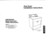
1
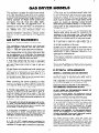
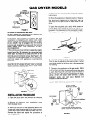
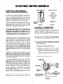
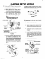
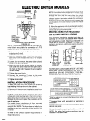
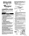
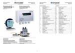
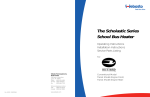
TIMING
INSTALLATION
INSTRUCTIONS
for
LINE
UP NOTC
TO CLEAR
RATCHET
HUB
COMMERCIAL
DRYERS
Before you begin, read the following
completely
and carefully.
They will
installation.
After completing the installation,
tions for future use.
instructions
simplify
the
SAFETY
Immediately
IF YOU
call your
SMELL
1
caution in a prominent location.
install the dryer up against draperies or
or on carpet and be sure to keep any and
from falling or collecting behind the dryer.
NON COIN MODELS
On non coin operated models, the console houses
the accumulator
timer with actuating
arm and
button.
INSTALLING
AND REPLACING
NYLON
CAMS ON ACCUMULATOR
MECHANISMS
INSTALL
BEFORE COMPLETING
2. Replacement
gas supplier
It is recommended
that the operator
post, in a
prominent location, instructions
for the customer’s
use in the event the customer smells gas. This information should be obtained from your local gas
supplier.
Post this
NEVER
curtains
all items
FIGURE 1
ELECTRICAL
CONNECTION
cam
of new timing
cam
a. Place cam (hub down) over clock shaft, lining
up flat on shaft with flat of cam hole. (Be sure
drive lug is in place.)
b. Rotate cam until “V” notch lines up with
ratchet tooth.
c. Press down to seat cam on motor shaft. Make
sure that “V” notch freely clears ratchet tooth.
INSTALLING
OR CHANGING SLIDE MECHANISM
1. Remove the service access door of the meter
case. Lift the service access door top up at the back
to remove. On new dryers install the service access
door lock.
2. Carefully remove and insert the coin slide mechanism through
the opening in the front of the
meter case console.
3. Secure the coin slide mechanism with the 3/16”
bolt (supplied in the parts bag) from inside the
meter case (See Figure 2).
COIN OPERATED MODELS
On models equipped with a coin operated console,
the console houses the accumulator
timer. Coin
slide mechanism access door lock, key and coin
vault and key can be supplied by the same source
that furnished this dryer.
The accumulator
timer is set to accumulate 30 minutes (6 pins) drying time for each coin deposited.
Two additional timing cams for 20 minute (9 pins)
and 45 minute (4 pins) time increments are included
in the miscellaneous
parts bag.
TIMING
a. Rotate cam by hand until “V” notch lines up
underneath the ratchet tooth. (See Figure 1)
b. Insert narrow screwdriver
under nylon cam,
close to the clock shaft. Lift gently off shaft. Make
sure that pressure is directly upward and the “V”
notch clears the ratchet tooth.
GAS:
DO NOT store or use gasoline or other flammable vapors and lrqurds In the vrcrnrty of thus
1 or any other ~~~~~:.,‘FETy’
DOWN
1. Removal of nylon timing
save these instruc-
GENERAL
FOR YOUR
CAM
FIGURE 2
GAS DRYER MODELS
7. The dryer and its individual
shutoff valve must
be disconnected
from the gas supply piping sytem
during any pressure testing of that system at test
pressures in excess of l/2 psig (3.45 kPa). The
dryer must be isolated from the gas supply piping
system by closing its individual
manual shutoff
valve during any pressure testing of the gas supply
piping sytem at test pressures equal to or less than
l/2 psig (3.45 kPa).
This appliance is suitable for mobile home installations. The installation
of the dryer must conform
to the Manufactured
Home Construction
and Safety
Standard, Title 24 CFR, Part 32-80 [formerly
the
Federal Standard for Mobile Home Construction
and Safety, Title 24, HUD (Part 280), 19751.
For mobile home use, this appliance MUST be
fastened to the floor and MUST be exhausted to
the outside. Order Mobile Home Installation
Kit
No. 346765
from your Whirlpool
Dealer. Kit
includes
the necessary fastening
hardware
and
detailed installation
instructions.
Exhaust system
hardware is also available through your Whirlpool
Dealer.
8. If local codes permit, it is recommended
that
flexible metal tubing be used for connecting
the
appliance
to the gas supply line. (The gas feed
pipe, which extends through the lower rear of the
appliance is provided with a Ye” male pipe thread.)
GAS SUPPLY REQUIREMENTS
OBSERVE
ALL GOVERNING
9. If rigid pipe is used as a gas supply line, a
combination
of pipe fittings must be used to obtain
an in-line connection to the dryer.
CODES AND ORDINANCES
This installation
must conform
with American
National Standard, National Fuel Gas Code ANSI
2223.1 - 1980, and local codes and ordinances.
lO.Make sure the lower edges of the cabinet, plus
the back and bottom sides of the dryer are free of
obstructions
to permit adequate clearance of air
openings for combustion air.
Input ratings shown on the rating plate (serial tag)
are for elevations up to 2,000 feet. For elevations
above 2,000 feet, ratings should be reduced at a rate
of 4% for each 1,000 feet above sea level.
1 l.For ease of installation,
operation and servicing
(if ever needed) adequate space should be provided
around the dryer.
1. First make certain that this dryer is equipped
with the correct orifices for the particular
type of
gas used. Check local utility for type of gas and
BTU rating.
12.The wiring diagram is located inside the lower
access panel. See page 3 for instructions on opening
of the access panel.
All gas dryers are manufactured
with natural gas
(Type 1) burner assemblies. In areas using mixed
gas (Type 2) or manufactured
gas (Type 3) it is
necessary to use replacement orifices as specified
for the main burner. Refer to service manual charts
for determining
correct orifice sizes.
ELECTRICAL
OBSERVE
REQUIREMENTS
ALL GOVERNING
CODES AND ORDINANCES
A 120 Volt, 60 Hz, AC only, 15 Ampere fused
electrical
supply is required (time delay fuse or
circuit breaker is recommended).
It is recommended
that a separate circuit serving only this appliance
be provided. DO NOT use an extension cord.
Electrical ground is required on this appliance.
When converting
the burner assembly to either
butane or propane (LP) gas, a special conversion
kit is required. Refer to service manual to determine
conversion kit for particular gas usage.
RECOMMENDED
2. Provide a gas supply line of l/z” pipe to the dryer
location.
(If dryer is to be used on LP gas, Ye”
approved copper tubing may be used.) If the total
length of the supply line is more than 20 feet, use
larger pipe. Pipe thread compounds suitable for the
type gas should be used.
GROUNDING
METHOD
DO NOT, UNDER ANY CIRCUMSTANCES,
POWER SUPPLY CORD GROUND PRONG.
REMOVE
THE
For your personal safety, this appliance
must be
grounded. This appliance is equipped with a power
supply cord having a 3-prong grounding plug.
To minimize possible shock hazard, the cord must
be plugged into a mating 3-prong grounding
type
wall receptacle, grounded
in accordance
with the
National Electrical Code ANSI/NFPA
No. 70-1984
and local codes and ordinances. If a mating wall receptacle is not available, it is the personal respondsibility and obligation
of the customer to have a
properly grounded 3-prong wall receptacle installed
by a qualified electrician. See Figure 3.
3. The supply line should be equipped with a shutoff valve. This valve should be located in the same
room as the dryer and should be in a location that
allows ease of opening and closing.
4. If the dryer is installed in a confined area such
as a bathroom or closet, consideration
should be
given to provide enough air for combustion
and
ventilation.
(Check local codes and ordinances.)
For added personal safety, using the clamp and
green colored copper wire furnished, connect this
separate ground wire (#18 minimum)
from the
external ground connector on the back of the appliance to a grounded cold water pipe.* See Figure 4.
5. Wall spacings see page 6.
6. A l/8 inch NPT plugged tapping, accessible for
test gage connection,must
be installed immediately
upstream of the gas supply connection to the dryer.
2
GAS DRYER MODELS
J-PRONG
GROUNDING TYPE
WALL RECEPTACLE
J-PRONG
3-PRONG
GROUNDING
PLUG
4. Refer to Exhaust
instructions.
\
System Requirements
-r
in these
5. Move the appliance to desired location. Observe
the minimum
clearance
to sides and rear as
specified on the label found on back panel of the
dryer.
To open the toe panel use a putty knife, press on
the toe panel lock located at the center top of the
toe panel. Pull downward on the toe panel to open.
The toe panel is hinged at the bottom. See figure 5.
POWER SUPPLY
CORD
FIGURE 3
ALTERNATE
GROUNDING
METHOD
DO NOT, UNDER ANY CIRCUMSTANCES,
POWER SUPPLY CORD GROUND PRONG.
REMOVE
THE
If changing
and properly
grounding
the wall
receptacle, is impossible
and where local codes
permit (consult your electrical
inspector),
a temporary adapter may be plugged into the existing
2-prong wall receptacle to mate with the 3-prong
power supply
cord. THIS, HOWEVER, IS NOT
RECOMMENDED.
If this is done, you must connect a separate copper
ground wire (No. 18 minimum) to a grounded cold
water pipe* by means of a clamp and then to the
external ground connector screw. See Figure 4. Do
not ground to a gas supply pipe. Do not connect to
electrical
supply until appliance
is permanently
grounded.
*Grounded
cold water pipe must have metal continuity
to electrical
ground
and not be interrupted
by plastic,
rubber or electrically
insulating
connectors
(including
water
meter or pump)
without
adding a jumper wire at these connections.
TOE PANEL
-
I
FIGURE 5
6. Level the appliance from side to side and from
front to rear by adjusting the leveling feet. A small
spirit level placed on the dryer top is recommended
for leveling.
7. Connect the appliance to the gas supply. Make
sure the shut-off valve located behind the toe plate
is open (See Figure 6) and open shut-off valves in
the supply line. Test all gas connections
for leaks,
using a brush and soapy water solution.
(Liquid
detergent
works very well also.) Bubbles will
indicate a loose connection.
NEVER TEST FOR GAS LEAKS WITH A FLAME.
120 VOLT 3.PRONG
RECEPTACLE
I15 AMPI
INSTALLATION
PROCEDURE
1. Open the dryer
door and remove the shipping
tape that holds the d’rum to. the cabinet.
2. Remove all literature
from-the dryer drum.
and
installation
GAS SHUT-OFF
VALVE
(OPEN1
parts
3. Block up the front of the appliance about four
inches and install leveling feet in the front corners.
These feet should extend approximately
one inch.
Remove the block and repeat the procedure
at
rear of appliance.
l/2
INCH GAS PIPE 13/B INCH APPROVED
COPPER
TUBING
MAY BE USED ON LP GASI
FIGURE 6
DRYER MODELS
ELECTRICAL
OBSERVE
4 WIRE RECEPTACLE
REQUIREMENTS
ALL GOVERNING
CODES AND ORDINANCES
G
A three-wire or four-wire single phase 120/240 volt
60 Hz AC only electrical supply (or three-wire or
four-wire 120/208 volt if specified on nameplate) is
required on a separate 30 ampere circuit, fused on
both sides of the line (time-delay fuse or circuit
breaker is recommended).
Do not fuse neutral.
-G+
v+)x
W
RECEPTACLE
(14.30RI
THE DRYER MUST BE CONNECTED
TO COPPER WIRE ONLY. Aluminum
wire must not be
used at the dryer appliance terminal block, to avoid
potentially
unsatisfactory
connections.
ELECTRICAL
Local codes may permit the use of a flexible type
30 ampere power supply cord (pigtail)
with no
smaller than #lO copper wire to match three-wire
receptacle of NEMA Type lo-30R shown in Fig. 7.
A suitable strain relief must be provided at the point
the power supply cord enters the appliance.
CONNECTION:
It is the personal responsibility
of the customer to
contact a qualified
installer
to assure that the
electrical
installation
is adequate and is in conformance with the National Electrical
Code and
local codes and ordinances.
Electrical
ground is required on this appliance.
This appliance
is manufactured
with the neutral
terminal connected to the frame.
The appliance
may be connected
directly to the
fused disconnect
(or circuit breaker) box through
flexible armored or non-metallic
sheathed copper
cable. Allow two or three feet of slack in the line
between the wall and the appliance so that it can
be moved if servicing is ever necessary. A suitable
strain relief must be provided at each end of the
power supply cord (at the appliance
and at the
junction
box). Wire sizes (COPPER WIRE ONLY)
and connections
must conform with the rating of
the appliance (30 amperes). Do not use an extension
cord.
A.
If local codes permit connection
of the frame
grounding
conductor to the neutral wire of the
power supply cord:
(1) Remove the terminal
block cover.
the neutral
wire of the power
(2) Connect
supply cord to the center silver colored
terminal of the terminal block and connect
the other wires to the outer terminals. See
Fig. 9. For connecting
plain-end field wire,
see Fig. 14.
CAUTION: For mobile home installations,
the appliance wiring
must be revised: the appliance
frame must not be connected to the neutral terminal,
but must be connected to the ground wire (green)
of the power supply cord.
(3) Replace terminal
block cover.
EXTERNAL
GROUND
CONNECTDR
If four-wire
receptacle
of NEMA Type 14-30R is
used (see Fig. 8), a matching power supply cord
(pigtail)
must be used. This cord contains
four
#lO copper conductors with space or ring terminals
on dryer end terminating
in a NEMA ?ype 14-30P
plug on supply end. The fourth (grounding)
conductor Tust be identified by a green cover and the
neutral conductor
by a white cover. Cord should
be Type SRD or SRDT, with strain relief and be at
least 4 feet long. The power supply cord and strain
relief are not provided with the dryer.
Typical 30 ampere receptacles
codes permit use of flexible
(pig?ail).
FIGURE 8
FIGURE 7
GROUND WIRE
(GREEN)
NEUTRAL
(WHITE OR
CENTER)
for use where local
power supply cord
TO FUSED DISCONNEC
BOX OR APPROVED
WIRING DEVICE FOR
POWER SUPPLY CORD
POWER SUPPLY CORD
WITH STRAIN RELIEF)
30 AMPERES)
GROUNDEDNEUTRAL
FIGURE 9
4
ELECTRIC
DRYER MODELS
6. If local codes DO NOT permit frame grounding
to the neutral wire of the power supply cord:
(1)
Remove terminal
*Grounded
cold water pipe must have metal continuity
to electrical
ground
and not be interrupted
by plastic,
rubber or electrically
insulating
connectors
(including
water
meter or pump)
without
adding a jumper wire at these connections.
See FIG. 12
block cover.
(2) Remove the ground wire (green) from the
external ground connector and fasten under
center silver colored terminal block screw.
(3) Connect
the neutral wire of the power supply
cord to the center silver colored terminal
of the terminal block and connect the other
wires to the outer terminals.
See Fig. 10.
For connecting
plain-end
field wire see
Fig. 14.
FIGURE
12
CONNECT SEPARATE
COPPER GROUND WIRE
FROM EXTERNAL
GROUND CONNECTOR
TO APPROVED
GROUND
C. If connecting
to a four-wire
(mobile home):
‘,
electrical
,’
b-3,
CENTER
SILVER
COLORED
TERMINAL
BLOCK
SCREW
(1) Remove terminal
CENTER)
-
block cover.
(2) Remove the ground wire (green) from the
external ground connector and fasten under
center silver colored terminal block screw.
GROUND WIRE
(GREEN)
COPPER
POWER SUPPLY CORD
(WITH STRAIN RELIEF)
30 AMPERES)
(3) Connect
the ground wire (green) of the
power supply cord to the external ground
connector.
TO FUSED DISCONNECT
BOX OR APPROVED
WIRING DEVICE FOR
POWER SUPPLY CORD
(4) Connect
UNGROUNDED
FIGURE
the neutral wire (white) of the power
supply cord to the center silver colored
terminal of the terminal block and connect
the other wires to the outer terminals. See
Figure 13. For connecting
plain-end
field
wire, see Figure 14.
NEUTRAL
10
(4) Connect
a separate copper ground wire
(#lo minimum) to a grounded
cold water
pipe’ by means of a clamp and then to the
frame of the appliance
at the external
ground connector. Use Part #685463 ground
wire and clamp assembly. Do not ground to
a gas supply pipe. Do not connect the power
supply cord to electric power supply until
appliance
is permanently
grounded.
See
Fig. 11.
(5) Replace
terminal
EXTERNAL
GROUND
\
block cover.
CONNECTOR
.‘J,.,
GREEN WIRE OF HARNESS
GREEN WIRE
(5) Replace
system
terminal
block cover.
EXTERNALGPO”ND
NEUTRAL
(WHITE 0R
CENTER)
TO FU”‘”
JCY “Ia_Ic
Ia_”
CONNtr.CCII DVA
FOUR WIRE POWER
- j+.SiJPPLY
CORD (WITH
STRAIN RELIEF)
(30 AMPERES)
4 WIRE UNGROUNDED
FIGURE 13
FIGURE
11
5
NEUTRAL
ELE,CTRlC DRYER MODELS
.
.
&
+I
3”
I+
NOTE: For mobile home installations
the dryer must
be exhausted to the outside. If the dryer is exhausted
through the floor and the area under the mobile
home is enclosed,
it is recommended
that the
exhaust system terminate outside the enclosure.
Extension beyond the enclosure
will prevent the
accumulation
of lint and moisture under the mobile
home.
P
5. Move the applrdnce into its permanent position.
Level appliance from front to back and from side to
side by adjusting the leveling feet.
INSTRUCTIONS FOR RECESSED
OR CLOSET INSTALLATIONS
PLAIN ENDS
(30 AMPERES)
PLAIN-END
FIELD WIRING
FIGURE 14
NOTE: The terminal connections at the dryer terminal block are suitable for connection
of #lO
copper wire only. To install plain-end field wire:
The following
installation
spacings and door air
openings for the dryer are possible when installed
and exhausted as noted. (Spacing as indicated is in
inches and is minimum allowable.
For ease of installation and service, additional
spacing should be
considered.)
CLOSET
1. Strip outer covering back 3 inches from the end
exposing the 3 wires.
2. Strip the insulation back 1 inch from the end of
each wire. Form the bare wire into a “U” shaped
hook.
3. Loosen, do not remove, the center silver colored
screw of the terminal block.
4. Slide the end of the neutral (white or center)
wire under the screw head with the open side of
the hook on the right. Squeeze the wire together
to form a loop.
5. Tighten the screw firmly.
6. Connect the remaining
2 wires to the outer
screws the same way. Tighten screws firmly.
7. Tighten
SIDE VIEW
FRONT VIEW
(DOOR NOT
SHOWN1
FIGURE
FRONT VIEW
15
TO PREVENT LARGE AMOUNTS OF LINTAND
MOISTURE
FROM ACCUMULATING
AND TO
MAINTAIN
DRYING
EFFICIENCY,
THIS MACHINE MUST BE EXHAUSTED
OUTDOORS.
MINIMUM
INSTALLATION
SPACINGS
strain relief.
INSTALLATION
-~I
PROCEDURE
1. Open the dryer, door and remove the shipping
tape holding the dryer drum to the cabinet.
.2. Remove all literature
the dryer drum.
and installation
parts from
11
3. Block up the front of the appliance about four
inches and install leveling feet in the front corners.
These feet should extend approximately
one inch.
Remove the block and repeat the procedure at the
rear of appliance.
For mobile home installations
all floor mounted
dryers must be fastened to the floor during transit
using Kit No. 346765. The dryer does not need to be
fastened to the floor while the mobile home is not
in transit.
4. Refer to the Exhaust
these instructions.
System
Requirements
in
Unobstructed
air openings required
equipment
when door is installed.
*Shelf or cabinet
non-exhausted.
**Louvered
acceptable.
***‘ID”
cabinet
is not permitted
door
Dimension
rear panel’.
Companion
with
equivalent
for laundry
above dryer when
air openings
is
must be measured from dryer
appliancespacings
NOTE: No other fuel burning
installed in the same closet.
should be considered.
appliance
may be
EXHAUST
SYSTEM
REQUIREMENTS
elbows and the type of exhausted hood. The maximum length for both rigid and flexible
duct is
shown in the chart, FIG. 17.
1. CAUTION: FOR YOUR PERSONAL SAFETY DO NOT
EXHAUST DRYER INTO A CHIMNEY, FURNACE COLD
AIR DUCT OR ANY OTHER COMMON DUCT, ATTIC OR
CRAWL SPACE. ACCUMULATED
LINT COULD BECOME
A FIRE HAZARD OR MOISTURE COULD CAUSE DAMAGE.
EXHAUST
NUMBER
DO NOT USE 3 INCH EXHAUST
DUCT
HOOD
TYPE
Of
90 TURNS
2. You can get the parts you need for installation
from your Whirlpool parts distributor
or your local
plumbing and heating store.
36 FT
26 FT
3. We strongly recommend exhausting the dryer to
the outside to prevent large amounts of moisture
and lint from being blown into the room.
16 FT.
16 FT.
10 FT
I
SEE
CHART
I
-.
ELECTRlC
]
4.3/4r
f
28-114”
4”
*
t
3s’
E XHA”.ST
14 19/32-
_GAS1
q;
19.3/8”
-
1
,-,,4.’
BACKVIEW
1%
AZ
1”
F,G”,-jE
,6
Non coin model
Coin model
NEVER
INSTALL
DUCT CONCEALED
SIDEVIEW
may be routed
through the wall.
up, down,
ANY TYPE OF FLEXIBLE
IN WALLS OR CEILING
TYPICAL EXHAUST INSTALLATIONS
A
7-I/8”
7-718”
EXHAUST
HOODd:
I
RIGID METAL
DUCT
,,
d
A’1
J.,.
-‘*,
I
7,. :;/ 1
6. We strongly recommend exhausting with 4 inch
diameter rigid METAL duct. We strongly recommend METAL flexible duct if you use flexible duct.
Flexible
aluminum
duct is available from your
Whirlpool
dealer or parts distributor.
NEVER
USE SMALLER
THAN 4 INCH EXHAUST
DUCT.
7. The exhaust
right or straight
DUCT
11. Exhaust systems longer than specified will shorten the life of the dryer and result in reduction of
performance
such as longer drying time and increased use of energy. Lint may also accumulate
creating a possible safety hazard. The exhaust system should be cleaned periodically,
at least every
two years.
12. We do NOT RECOMMEND
non-metallic
flexible duct. If you use non-metallic
flexible duct you
must connect a METAL elbow and at least 2 feet
of METAL duct to the dryer outlet. The length of
the non-metallic
flexible duct should not exceed 7
feet, and it must be adequately supported to prevent sagging or kinking. See FIG. 18.
‘---t’
“2”
\,I
I
A
METAL
FIGURE 17
10.
Use duct tape to seal all joints. Never use
screws to assemble the ductwork, screws can catch
lint.
5. Exhaust outlet at rear of the dryer is located as
shown in Figure 16. Detailed instructions on spacing
for side and rear clearances can be found in the section “Instructions
for Recessed or Closet Installations.”
Information
on minimum spacing side to
side and to the rear is also found on a label located
on back panel.
F-J---3 I ’
METAL
24 FT
4. If you cannot exhaust your dryer to the outside,
use Exhaust Deflector Kit LCK4000 available from
your Whirlpool Dealer.
/-Iz
r----\
RIGID
FIGURE
18
!, L.I ~*,b=
RECOMMENDED
IMPORTANT:
PROPER
SUPPORT IS REOUIRED+y’,EXHAUST
left,
FLEXIBLE
8. The exhaust duct should terminate with an exhaust hood to prevent back drafts. The outlet of
the hood must be at least 12 inches from the
ground or any obstruction.
A louvered exhaust
hood, Part Number 279399 is available from your
Whirlpool
dealer or parts distributor.
An exhaust
hood with a 2% inch outlet creates more back pressure, but may be used with shorter systems. Never
use an exhaust hood with a magnetic latch.
1
VINYL
HOOD
ALTERNATE
For your personal safety, a metal elbow and at least 2 feet of
metal duct must be used at the outlet of the dryer. This
reduces the possibility
of lint blocking
the exhaust,system
and minimizes
the potential
of a fire hazard. The 2 feet of
metal duct also helps make any service that may be needed
easier and prevents crushing the flexible duct when the dryer
is moved to its final operating
location.
9. The maximum length of the exhaust system depends upon the type of duct used, the number of
7
IMPORTANT
OPERATING
2. Remove air from gas supply
(after completing
the installation):
All models as received may have some accumulated time remaining on the timer due to factory testing. After connecting the electrical supply, use the following to check operation.
2. To start drver:
NOTE: Loading door must be closed for dryer
to operate.
a. Non coin operated
models:
Push timer set
button
down.
(Operating
time will accumulate
per number of depressions and type of timing cam
used.) Push START/RESTART
button. Dryer will
stop when ti,me is used up.
b. Coin operated models: Insert coins in slide and
push in slowly. Operating time will accumulate per
number of coins and type of timing cam used.
Depress Push-to-Start button. Dryer will stop when
time is used up.
MOVING OPERATIONS PROCEDURE
GAS DRYER MODELS
1. Remove power cord from wall socket, coil it and
tape it to back of dryer.
2. Close shut-off valves in gas supply line and
behind dryer toe plate.
3. Disconnect
gas pipe and remove protruding
fittings from dryer.
4. Cap the open fuel line running to gas meter.
ELECTRIC
c. When door is opened dryer stops, but timer
continues to run. To restart, close door and push
START/RESTART
button.
DRYER MODELS
1. Shut off electric
supply
to the dryer.
2. Disconnect
power supply
the.dryer terminal block.
3. If drying time is too long, make sure !int screen
is clean.
4. Periodically
inspect motor and blower for lint
accumulation.
Large quantities
of lint in these
areas will affect performance
of the dryer.
valve IS open and gas is
SHOWING COMPLETE TYPICAL
120 VOLTS
RECEPTACLE
or cable
INSTALLATIONS
3 CONDUCTOR
(15 AMP)
EXHAUST
CONN
cord
DUCT
ELECTRIC DRY ER
GROUND
WIRE
(ALTERNATE)
;ROUND
CLAMP
GAS DRYER
D WATER
PIPE
iiAS
TYPICAL ELECTRIC INSTALLATION
-
WhidpOd
Benton Harbor,
Part No. 687455
from
ALL DRYER MODELS
1. Make sure leveling legs are secure in dryer base.
2. Apply filament tape from Inside drum, out the
door opening to the front panel to prevent drum
movement.
3. Use masking tape to secure clothes door and
lint screen lid.
GAS DRYER MODELS
GROUND
as follows
b. If the burner does not ignite during these five
minutes of operation, shut off machine and wait
for 15 minutes, While waiting, check to be sure
all supply valves are open and electric supply is
connected. Repeat the above procedure until the
burner ignites.
1. Make sure the electric power is connected and
proper electrical contact made. Check fuses to be
sure they are good and tight.
ILLUSTRATIONS
line
a. Turn the dryer on and allow it to run for about
five minutes in a full heat cycle.
ALL MODELS
1. Make sure gas shut-off
available.
INFORMATlON
F VALVES
TYPICAL GAS INSTALLATION
CORPORATION
Michigan
8
SHUT-Of
49022