1
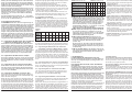
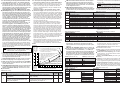
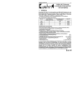
gestell und Überlastung des Decoders nicht ausgeschlossen.
Die zwei zusätzlichen Funktionsausgänge besitzen zugunsten
der höheren Strombelastbarkeit keine Schutzeinrichtungen.
the decoder. The two extra function outputs haven't got a protection mechanism for the benefit of the higher output current.
2. Important Information
2. Wichtige Hinweise
Lesen Sie vor der ersten Benutzung des Produktes bzw. dessen Einbau diese Bedienungsanleitung aufmerksam durch.
2.1. Das Produkt richtig verwenden
Dieser Lokomotivdecoder ist bestimmt
zum Einbau in Modelleisenbahnen
zum Betrieb an einem zugelassenen Modellbahntransformator bzw. an einer damit versorgten digitalen Modellbahnsteuerung
zum Betrieb in trockenen Räumen
Jeder darüber hinausgehende Gebrauch gilt als nicht bestimmungsgemäß. Für hieraus resultierende Schäden haftet der
Hersteller nicht; das Risiko hierfür trägt allein der Benutzer.
Read the operating instructions carefully before using the
product for the first time or assembling it.
2.1. Using the product correctly
This locomotive decoder is intended
for installation in model locomotives
for connection to an authorized model railroad transformer or
a digital model railroad control system connected to one
for operation in a dry area
Using the product for any other purpose is not approved and is
considered incorrect. The manufacturer cannot be held responsible for any damage resulting from the improper use of this
product; liability in such a case rests with the user.
Der Decoder darf nur in Modellbahnen eingesetzt werden!
The decoder is only allowed to be put in model railways!
Achtung: Ein Betrieb des Decoders auf analogen Wechselstromanlagen mit Umschaltimpuls ist nicht zulässig! Die
hohe Spannung des Umschaltimpulses führt zur Zerstörung des Decoders.
Please note: This decoder is not suitable for operation
with conventional AC supply and the voltage pulse for
change of direction! The high voltage of this pulse will
cause the destruction of the decoder.
3. Einbau des Decoders
3. Installing the Decoder
3.1. Vorbereitung
3.1. Preparation
Es können nur Lokomotiven mit einem Digitaldecoder ausgerüstet werden, die im Gleichstrombetrieb einwandfrei funktionieren. Besonders im Digitalbetrieb ist eine sichere und unterbrechungsfreie Stromaufnahme wichtig. Ersetzen Sie verschlissene Kohlebürsten und defekte Lämpchen und reinigen Sie die
Radschleifer. Der Decoder sollte an einer Stelle in der Lok eingebaut werden, wo mit der geringsten Wärmeentwicklung zu
rechnen ist.
Only locomotives, which run smoothly in analogue mode,
should be equipped with a digital decoder. A secure and uninterrupted current pickup is important especially in digital mode.
Change worn coal brushes and defect lights and clean wheel
pick-ups. The decoder should be installed inside the locomotive
in such a way as to avoid overheating.
Werkzeug: Verwenden Sie für den Decodereinbau einen Lötkolben mit max. 30 Watt Leistung (wenn vorhanden mit Temperaturregelung), Elektroniklötzinn (kein Lötfett) sowie Seitenschneider (zum Kürzen der Anschlussdrähte) und kleine
Schraubendreher. Zusätzlich benötigen Sie Isolierband (um Metallteile der Lok abzukleben) und doppelseitige Klebepads (z.B.
aus dem Lokdecoder-Einbauset 6819 von Viessmann) zum Befestigen des Decoders.
Vor dem Einbau des Decoders ist der Motor vollständig zu
isolieren, d.h. es dürfen keine elektrischen Verbindungen zwischen Motoranschlüssen und Radschleifer existieren. Merken
Sie sich, welcher Motoranschluss mit dem rechten bzw. linken
Radschleifer verbunden war.
Hinweis zu älteren Loks der Firma Fleischmann: Häufig ist
bei diesen Loks der Motorschild ein Teil der Motorstromversorgung und mit einem der Radschleifer verbunden. Um den Motor
zu isolieren, müssen Sie diese Verbindung auftrennen oder einen neuen Lagerschild einsetzen.
3.2. Strombelastbarkeit
Neben den gewünschten Funktionen und dem verfügbaren Einbauraum ist die Stromaufnahme des Lokmotors unter Volllast
wesentlich bei der Auswahl des richtigen Decoders.
Der Decoder 5246 kann einen Motorstrom von 1,1 A liefern. Angaben über die Stromaufnahme der Lok beziehen sich in der
Regel auf eine Spannung von 12 oder 14 Volt. Liegt die Digitalspannung Ihrer Digitalzentrale höher (z.B. Märklin Digital, Roco
Lokmaus I / II, LGB, Intellibox, Twin-Center), steigt die Stromaufnahme an und kann so eventuell den Wert von 1,1 A überschreiten. Für den Betrieb von Fahrzeugen der Spurweite H0
2
Tools: For installing the decoder please use a soldering iron
with 30 Watts max. (if possible with temperature control), electronic solder (no soldering paste) and side cutters (to shorten
the leads) and small screw drivers. You also need insulation
tape (to cover any metal parts of the locomotive) and double
sided tape (such as included in Viessmann locomotive decoder
installation set 6819) to fasten the decoder.
Before installing the decoder you have to completely insulate
the motor, which means there should not be any electrical connection between motor and wheel pick-ups. Don't forget which
motor terminals were connected with the right or left wheel pickup.
Advice for older Fleischmann locomotives: Often in these locomotives the motor shield is part of the motor's power supply
and therefore connected with one of the wheel pick-ups. To insulate the motor you have to cut off this connection or replace
the motor shield.
3.2. Maximum Current Load Capacity
Besides the desired functions and the available installation
space the current draw of the motor under full load determines
the selection of a suitable decoder.
The decoder 5246 supplies a motor current of 1.1 A. Values regarding current draw of the locomotives generally refer to a voltage of 12 or 14 V. Is the digital voltage of your command station higher (e.g. Marklin Digital, Roco "Lokmaus" I / II, LGB, Intellibox, Twin-Center), the current draw rises and could potentially exceed the permitted value of 1.1 A. For operating H0
gauge we recommend a track voltage of approx. 16 V.
The total current load capacity of the decoder 5246 in digital
mode is 1.2 A. If the motor draws e.g. 1.0 A, then the total
current available for all the light and function outputs is 200 mA.
nicht möglich.
Grundsätzlich gilt: Für die korrekte Rückmeldung beim Programmieren des Decoders ist eine Last am Motorausgang nötig!
Prinzipiell lassen sich so trotzdem alle Konfigurationsvariablen
(CVs) programmieren. Sie erhalten jedoch immer eine Fehlermeldung und können die CVs nicht auslesen.
Probleme entstehen jedoch bei mehrstufigen Programmierverfahren, z.B. bei der Intellibox oder beim Twin-Center das Programmieren einer langen Adresse. Die vierstellige Adresse wird
in zwei Werte aufgeteilt und einzeln programmiert. Da nach der
Programmierung des ersten Wertes keine Rückmeldung erfolgt,
meldet die Zentrale einen Fehler. Das Programmieren des zweiten Adressteils wird deshalb nicht ausgeführt!
7.5.2.
Verwendungshinweise
Um das Problem der mehrstufigen Programmierverfahren zu
umgehen, müssen Sie die beiden Adressteile manuell in CV#
17 und CV# 18 programmieren und anschließend in CV# 29
den erweiterten Adressmodus einstellen.
Soll z.B. die Adresse 2.110 eingestellt werden, müssen zuerst
die beiden Adressteile ermittelt werden. Zuerst ist 2.110 durch
256 zu teilen und der gerade Anteil plus 192 in CV# 17 einzutragen, hier also 200 (= 192 + 8). Der Divisionsrest (2.110 - 8 *
256 = 62) ist in CV# 18 zu programmieren. Die Nutzung der erweiterten Adressen wird durch Eintragen des Wertes von 32
(bei 14 Fahrstufen) bzw. 34 (bei 28 Fahrstufen) eingestellt.
Eine weitere Möglichkeit ist der Anschluss einer Last am Motorausgang (z.B. Widerstand von 100 Ohm oder Glühlämpchen).
Somit erfolgt wieder eine korrekte Rückmeldung und die Programmierung arbeitet fehlerfrei. Damit diese Last aber im normalen Betrieb nicht angesteuert wird, muss durch Einstellung
der Konfigurationsregister der Ausgang abgeschaltet werden.
Programmieren Sie in CV# 2 den Wert 1, in CV# 5 und CV# 6
jeweils den Wert von 2. Löschen Sie sicherheitshalber auch alle
Positionen der Geschwindigkeitstabelle (CV# 67 bis CV# 94).
Beim 5246 muss zusätzlich die Lastregelung ausgeschaltet
werden (siehe CV# 56)!
8. Umrechnungstabelle
Soll die Geschwindigkeitskennlinie genau an Ihre Lokomotive
angepasst werden, ist dabei die Umrechnungstabelle (Tabelle
9) hilfreich. An einem Beispiel soll ihre Nutzung erklärt werden:
Angenommen, Ihre Lokomotive fährt bei der höchsten Fahrstufe zu schnell. Aus diesem Grund soll die Höchstgeschwindigkeit
z.B. auf 80 % begrenzt werden (durch Begrenzung der Motorspannung auf 80 %). In das Konfigurationsregister "Maximalspannung" (CV# 5) ist ein Wert von 80 % einzutragen. In vielen
DCC-Zentralen müssen Sie den Wert von 80 % vorher in eine
für die Zentrale verständliche Form "übersetzen".
In der nachfolgenden Umrechnungstabelle finden Sie für 80 %
Motorspannung den dezimalen Wert "204". In der Tabelle ist nur
jeder 4. Wert eingetragen, Zwischenwerte können durch mitteln
einfach bestimmt werden.
Besonders leicht ist die Programmierung der Geschwindigkeitskennlinie mit der PC-Software WINiPRO (Viessmann-Art.-Nr.
1021). Dort erfolgt in Verbindung mit der Intellibox, dem TwinCenter oder dem Interface von Lenz die Einstellung grafisch per
ziehen mit der Maus.
During programming the command station writes a value into
the memory of the decoder. Thus the values will be stored even
after an interruption of the track voltage. If this procedure is
carried out successfully the decoder turns on the motor output.
The current that is now flowing through the motor indicates to
the command station that the programming has been completed
successfully. If there is no motor in the circuit, there is no
current, which in turn results in an error display. Therefore it is
not possible to read out any CVs.
The basic rule is: To assure the correct feedback from the
decoder to the command station a load has to be connected to
the motor output!
Nevertheless you can program any CV as desired. However,
you will always get an error display and you will not be able to
read out any CV values.
This becomes more difficult when using multi-tiered programming methods, e.g. when programming an extended address
(4-digit address) with the Intellibox or the Twin-Center. The 4digit address has to be divided into two values that have to be
entered individually. Since there is no feedback after entering
the first two digits, the command station will display an error
message and because of that the second part of the address
cannot be programmed.
7.5.2.
Application Advise
To avoid the multi-tiered programming method you have to
enter both parts of the extended address separately into CV#
17 and CV# 18. You also have to activate the extended address
mode in CV# 29.
Let's assume you want to set the address 2110. first you have
to establish the two parts of this address. Divide 2110 by 256,
round the result and add 192, then enter this value into CV# 17
in this example: 200 (= 192 + 8). The remaining amount of this
calculation (2110 - 8 * 256 = 62) has to be entered into CV# 18.
To activate the extended address enter the value 32 (when operating with 14 speed steps) respectively 34 (when operating
with 28 speed steps) into CV# 29.
Another option is to connect a load to the motor output (e.g. a
100 Ohm resistor or an incandescent lamp). This allows the
correct feedback to the command station and programming
works without fail. To avoid that this load is actually powered
during normal operation you have to switch off this output by
programming several CVs. Enter the value 1 in CV# 2, and 2 in
CV# 5 and CV# 6. To play it save delete all values in the speed
table (CV# 67 to CV# 94).
When using the 5246 (with load control) you also have to deactivate load control (see CV# 56)!
8. Conversion Table
If you want to adapt the speed curve precisely to your locomotive, the conversion table (table 8) will be helpful. The following
example explains how to use it:
Let's assume your locomotive drives too fast at the highest
speed step, and you want to reduce the maximum speed e.g. to
80 % (through reducing the motor voltage to 80 %). Enter a
value of 80 % into the configuration register maximum speed
(CV# 5). To be able to program the DCC command station the
value must be "translated”.
In the following table you find a numerical value of 204 for 80 %
motor voltage. The table contains only every fourth value; all
other values can be interpolated.
Very easy is the programming of the speed curve by using the
PC-Software WINiPRO (Viessmann article # 1021). Combined
with the Intellibox, the Twin-Center or the interface from Lenz
you are able to define the speed curve graphically by drawing it
with the mouse.
15