1
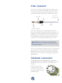
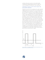
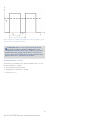
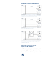
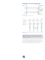
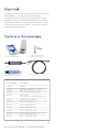
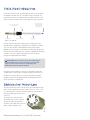
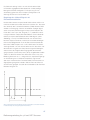
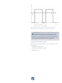
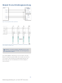
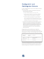
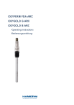
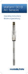
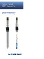
Arc pH and
ORP Sensors
Operating Instructions
Bedienungsanleitung
Important Note
The reproduction of any part of this document in any form is
forbidden without the express written agreement of Hamilton
Bonaduz AG.
Contents of this manual can be modified without previous
announcement. Technical modifications reserved. Greatest possible care was used on the correctness of the information in this
manual. If errors should be discovered nevertheless, Hamilton
Bonaduz AG is pleased to be informed about it. Regardless of
this, Hamilton Bonaduz AG cannot assume liability for any errors
in this manual or for their consequences.
Wichtiger Hinweis
Die Reproduktion irgendeines Teils dieses Dokuments in jeder
beliebigen Form ist ohne die ausdrückliche schriftliche Zustimmung der Hamilton Bonaduz AG untersagt.
Der Inhalt dieses Handbuchs kann ohne vorherige Ankündigung geändert werden. Technische Änderungen vorbehalten.
Es wurde grösstmögliche Sorgfalt auf die Richtigkeit der Informationen in diesem Handbuch verwendet. Sollten dennoch
Fehler entdeckt werden, würde sich die Hamilton Bonaduz AG
freuen, darüber informiert zu werden. Ungeachtet dessen kann
die Hamilton Bonaduz AG keine Haftung für etwaige Fehler in
diesem Handbuch oder deren Folgen übernehmen.
Table of Contents
Introduction................................................................... 4
Liability.......................................................................... 4
Intended Use................................................................. 5
Safety Instructions........................................................ 5
Initial Operation............................................................. 6
Electrical Connection.................................................... 6
Electrical connection of the
4–20 mA current interfaces.......................................7
Examples of circuit arrangement............................. 10
Electrical connection for the
digital RS485 interface............................................ 10
Examples of circuit arrangement............................. 12
Configuration and Monitoring of the Sensor............... 13
Preparation for Measurement..................................... 14
Removal of the Sensor................................................ 14
Sterilization, Autoclaving, CIP Procedures.................. 14
Testing and Maintenance............................................ 15
Calibration.............................................................. 15
Cleaning................................................................. 18
Regeneration.......................................................... 18
Self-diagnosis functions.......................................... 18
Disposal....................................................................... 19
Parts and Accessories................................................ 19
Technical Data............................................................. 20
3
Arc pH and ORP Sensors Operating Instructions
Introduction
This manual refers to the EASYFERM™ PLUS Arc™, POLILYTE™
PLUS Arc, EASYFERM PLUS ORP (Oxidation Reduction Potential)
Arc and POLILYTE PLUS ORP Arc group of sterilizable pH and
ORP sensors from Hamilton Bonaduz AG. These sensors are
compatible with all other components of the Hamilton Arc System,
including a complete family of intelligent sensors for pH, ORP, dissolved oxygen and conductivity measurements in process control.
Designation
Order number P/N
EASYFERM PLUS Arc
242091/242092/
242093/242094
120/225/325/425 mm
EASYFERM FOOD Arc
120/225/325/425 mm
POLILYTE PLUS Arc
120/225/325/425 mm
EASYFERM PLUS ORP Arc
120/225/325/425 mm
POLILYTE PLUS ORP Arc
120/225/325/425 mm
242120/242121/
242122/242123
242111/242112/
242113/242114
243050/243051/
243052/243053
243060/243061/
243062/243063
Hamilton Arc sensors are quality products manufactured
according to the very latest research findings. Follow the
instructions in this manual to ensure optimal safety and durability.
IMPORTANT: These instructions must be read,
understood and followed by all staff using Arc pH and
ORP sensors. Hamilton can assume no responsibility for
damage and/or operational disruption arising from failure
to observe these instructions.
Liability
The liability of Hamilton Bonaduz AG is detailed in the document
“General Terms and Conditions of Sale and Delivery,” chapter 12.
Hamilton is expressly not liable for direct or indirect losses arising
from use of the sensors. It must in particular be insured in this
conjunction that malfunctions can occur on account of the
inherently limited useful life of sensors contingent upon their
relevant applications. The user is responsible for the calibration,
maintenance and regular replacement of the sensors. In the case
of critical sensor applications, Hamilton recommends using
back-up measuring points in order to avoid consequential damages. The user is responsible for taking suitable precautions in the
event of a sensor failure.
Intended Use
Arc pH and ORP sensors were developed for the measurement
of the pH and ORP values in liquids. The engineering design is
based on Hamilton pH-sensitive glass and ORP sensitive platinum
elements. The patented reference system guarantees excellent
measurement stability.
The main application for Arc pH and ORP sensors is in-line measurement under demanding conditions in biotechnology using
products such as the EASYFERM PLUS Arc and EASYFERM
PLUS ORP Arc and the general chemical industry with POLILYTE
PLUS Arc and POLILYTE PLUS ORP Arc sensors. During development, special attention was paid to an optimum sanitary design.
Arc pH and ORP sensors provide both standard analog (4–20 mA)
and digital Modbus interfaces. These are built into each sensor
and are supported directly from the sensor. They do not require
any additional equipment such as an amplifier or transmitter.
Safety Instructions
Arc pH and ORP sensors must be used for their intended
applications, and in optimum safety and operational conditions.
The specifications (such as temperature or pressure) defined in
the section entitled “Technical data” must not be surpassed under
any circumstances. Potential hazards exist if the sensor is not
operated correctly or appropriately.
Assembly and maintenance must be performed only by
trained personnel.
Make sure that the PG 13.5 thread and the O-ring are not damaged when screwing the sensor into the process. O-rings are
consumable parts which must be replaced regularly and at least
once per year. Even when all required safety measures have been
complied with, potential risks still exist with respect to leaks or
mechanical damage to the sensor housing. Wherever there are
seals or screws, gases or liquids can leak out undetected.
Before removing the sensor from its measurement setup, always
make sure that no process medium can be accidentally leaked.
The built-in temperature sensor is intended only for monitoring the
sensor conditions, not for controlling the process temperature.
5
Arc pH and ORP Sensors Operating Instructions
Initial Operation
This Arc sensor has been carefully tested and is ready for use.
Always check a sensor for possible defects after first unpacking
it. In the unlikely event that you find a damaged sensor, return it
immediately in original packing to your Hamilton representative.
Arc logo, serial
and part number
O-ring
Socket head
with VP8
connector
PG 13.5 thread
Sensor tip with pHsensitive glass or ORP
sensitive platinum element
Sensor shaft
Figure 1: Arc Sensor
The Arc pH and ORP sensors are delivered directly from the
factory pre-calibrated according to operational specifications. The
integrated 4–20 mA analog interface and RS485 digital interface
(Modbus RTU) are configured according to factory defaults. You
can find full details, including serial number and most important
specifications, on the certificate provided with each sensor.
ATTENTION! To avoid drying out the diaphragm and
a potential decrease in sensor performance, make sure
the sensor is always stored with a cap containing Storage
Solution (P/N: 238931).
To be sure to avoid electrical damage to the sensor, carefully follow
all the instructions in the section entitled “Electrical Connection.”
Before application of the sensor for measurement, monitoring or
regulation, be sure to first check its configuration by means of an
operational test.
Electrical Connection
The Arc pH or ORP sensor is fitted with a VP8 socket head
The eight golden contacts are denoted as pin A to pin H. For easy
identification of each pin, the head has a notch between pin A
and pin B.
For the easiest and safest
connection of Arc pH or ORP
sensors, always use Hamilton
VP8 cables, available in a range
of different lengths.
VP Pin
Function
A
4–20 mA interface (mA interface #2)
B
4–20 mA interface (mA interface #1)
C
Power supply: +24 VDC (7 to 30 VDC)
D
Power supply: Ground
G
RS485 (A)
H
RS485 (B)
Electrical connection of the
4–20 mA current interfaces
The 4–20 mA interface enables direct connection of the Arc pH or
ORP sensor to a data recorder, indicator, control unit or PLC with
analog I/O. Apart from the two wires used for 4–20 mA current loop
no additional equipment is required for analog signaling.
Arc pH or ORP sensors are delivered from the factory with the analog
4–20 mA interface active (see the included sensor certificate).
When using the 4–20 mA interface, pins have the following
designations with respect to VP cable conductor colors:
VP
Pin
VP8
Cable
A
4–20 mA three-wire interface,
functions as a current sink. It regulates
Coaxial
the input current according to the
core
sensor measurements. This interface
black
needs a separate power supply (pin B
transparent
or C). Factory default is assigned to a
temperature measurement.
Arc pH or ORP
4–20 mA two-wire interface, functions
as a current sink. It regulates the
input current according to the sensor
measurements. This interface can
be powered directly from 4–20 mA
two-wire current loop. Nominal power
of 60 mW must be provided. Factory
default is assigned to a pH or ORP
measurement.
B
Coaxial
shield
black
C
Coaxial
Power supply: +24 VDC (7 to 30 VDC).
core red
Max. power consumption: 150 mW
transparent
D
Coaxial
shield red
Power supply: Ground
The 4–20 mA interface is configured at the factory with the
range, value and measurement units as indicated on the
7
Arc pH and ORP Sensors Operating Instructions
certificate. Follow the instructions in the section entitled
“Configuration and Monitoring of the Sensor” to adjust the
sensor according to the requirements of your application.
Controlling 4–20 mA current interface signals by
pulse-width modulation
Hamilton Arc sensors use the method of pulse-width modulation
(PWM) to adjust the DC currents of the 4–20 mA interfaces corresponding to the measured values. In principle, the pulse width
(ti) of a rectangular signal with a constant frequency, the pulse
duty factor (ti / T), is modulated and afterwards demodulated by
a low-pass filter to generate continuous analog DC signals. The
resulting value yi corresponds to the average of the PWM signal
(see Figures 1 and 2). The PWM-loads of the Arc Sensors have
low-pass filters which are not able to eliminate all AC fractions
of the used PWM frequency of 3.5 kHz due to technical impossibilities. Therefore, the current signals of the 4–20 mA interfaces
are still overlaid by a certain AC current which should be masked
by lag smearing or input filters of the current input card of the
process logic control system (PLC). Recommended PLC settings are a sampling rate below 3 kHz, an averaging over more
than 1 s, and the use of galvanically separated inputs to avoid
oscillations. It is also possible to use mathematical functions or
isolating amplifiers for signal processing filtering if necessary.
For detailed technical advice about suitable isolating amplifiers,
please contact Hamilton technical support.
Figure 1: Progress of a rectangular signal with a period T and a pulse duration t1 for the
generation of an analog signal with the value y1.
Figure 2: Progress of a rectangular signal with a period T and a pulse duration t2 for the
generation of an analog signal with the value y2.
ATTENTION! The Arc sensor generates the 4–20 mA
signals by pulse width modulation (PWM) which is not
compatible to all PLC systems. Also a galvanic separation
between the power supply and the PLC is necessary for
correct sensor functionality when used in 4–20 mA setups.
Figure 5 illustrates a solution for the problem.
Analog interface 1 and 2
Galvanically not isolated, pulse width modulation with 3.5 kHz,
recommended PLC settings:
XX
Use galvanically separated inputs
XX
Sampling rate < 3 kHz and ≠ n * 3.5 KHz
XX
Average over > 1 s
9
Arc pH and ORP Sensors Operating Instructions
Examples of circuit arrangement
Figure 3: Two-wire loop wiring diagram for the 4–20 mA interface (mA interface #1). In
this wiring scheme, power is not supplied to the sensor VP pin C, therefore the wiring is
not applicable to a sensor with the Arc Wi Sensor Adapter or VISICAL™.
Figure 4: Three-wire loop wiring diagram for the 4–20 mA interfaces. The figure
represents both 4–20 mA interfaces at pin A and pin B.
Figure 5: The safest form of wiring, using an isolation amplifier. The figure represents
both 4–20 mA interfaces at pin A and pin B. For detailed technical advice, please
contact Hamilton technical support.
Electrical connection for the
digital RS485 interface
The digital RS485 interface enables communication with Arc pH
or ORP sensors for performing measurements, calibrating the
sensor and changing the sensor’s configuration parameters. Arc
pH or ORP sensors are always connected to digital controlling
devices as a Modbus slave. To function, they require a power
supply using VP8 pins C and D. See Figure 6 below. The section
entitled “Configuration and Monitoring of the Sensor” describes
operation in digital mode.
By using the correct access password the Arc System operator
can adapt Arc sensors to many tasks by:
XX
Selecting the 4–20 mA interface
XX
Scaling (configuring) the 4–20 mA interface
XX
Selecting the measured parameter:
XX
pH: pH; mV
XX
ORP: mV
XX
Temperature T: °C; K, °F
In addition, operators can read sensor information from the
RS485 interface such as:
XX
The sensor’s serial number, part number (P/N) and manufacturing
work order (lot) number (WO)
XX
The sensor’s firmware version
XX
The sensor’s status (e.g., operation hours, number of cleanings and
sterilizations, warnings and errors)
Additional information:
The Modbus RTU communication protocol corresponds to the
Modbus-IDA standard (see http://www.modbus.org). Arc pH and
ORP sensors use an open register set developed by Hamilton.
Additional information about the register content and structure
can be found at http://www.hamiltoncompany.com.
ATTENTION! Because all sensors are delivered with
factory-default settings, each sensor must be configured
for its specific application before first use (See the section
entitled “Configuration of the Sensor” for more information).
The pins for the digital RS485 interface have the following
designation with respect to VP cable conductor colors:
Arc pH
and ORP
VP
Pin
VP8 Cable
Power supply: +24 VDC
(7 to 30 VDC)
Max. power consumption
150 mW
C
Coaxial core
red transparent
Power supply: Ground
D
Coaxial shield
red
RS485 (A)
G
Yellow
RS485 (B)
H
Brown
In an electromagnetically noisy environment, it is advisable to
connect the VP cable shield to the ground. This significantly
improves resistance to noise and signal quality.
Arc pH and ORP Sensors Operating Instructions
11
Examples of circuit arrangement
Figure 6: Wiring diagram for the RS485 interface.
Figure 7: Multi-drop bus wiring for the Modbus two-wire mode. Each sensor functions as
a Modbus slave.
NOTE: In the connection scheme shown above, each
sensor must have the unique Modbus device address for
proper communication.
The serial Modbus connection between the RS485 port of the
master and the corresponding interfaces of the sensors has to
be ensured according to the EIA/TIA RS485 standard. Only one
sensor can communicate with the master at any time.
Configuration and
Monitoring of the Sensor
Two options are available for the configuration and monitoring of
a sensor:
1. Personal computer or notebook. The following additional equipment
and software is also required:
XX
Hamilton USB-RS485 Modbus converter (P/N: 242411)
XX
Hamilton freeware HDM Hamilton Device Manager available at
http://www.hamiltoncompany.com (follow the instructions in the
Device Manager’s user guide for installation and operation)
XX
Demo Cable (P/N: 355194). This cable includes a power adapter to
supply the sensor with operational power, and a plug to connect the
two RS485 conducting wires (yellow and brown) to USB-RS485. If
you use a standard VP8 cable, you must supply the sensor with an
external power source (pin C: 24 VDC; pin D: Ground).
2. Hamilton Arc View Handheld Package (P/N: 242180). The Handheld
Package represents an ideal desktop solution for Arc sensor
management. The Arc View Handheld included in the package is
a compact mobile wireless device with long battery life and broad
functionality. When using the handheld as a mobile wireless device,
each Arc sensor requires an Arc Wi Sensor Adapter (P/N: 242170).
The digital RS485 interface of the Arc pH or ORP sensor can
be accessed by operators working within a three-tier hierarchy.
Operator hierarchy levels and factory default passwords are
shown in the table below.
Operator
Status
Operator
Level
Password
User
U
Not required
Administrator
A
18111978
Specialist
S
16021966
Users can read basic data from sensor. Administrators can also
calibrate sensors. Specialists can calibrate and configure
sensors, and can see all data.
13
Arc pH and ORP Sensors Operating Instructions
Preparation for
Measurement
Prepare the sensor for measurement as follows:
1. Carefully remove the protective caps from the VP head and from the
sensor tip. Flush sensor shaft with water.
2. If using a pH sensor: Check inside of pH glass membrane for unwanted air bubbles. Shaking the sensor gently will cause any bubbles
to rise to the top.
3. Make sure that the sensor is configured as required. If in doubt, test
as described in the section entitled “Electrical Connection: RS485
Modbus Interface.”
4. Install the sensor (thread: PG 13.5).
5. Attach the Arc pH or ORP sensor according to the section “Electrical
Connection” in the desired configuration (analog 4–20 mA interface,
digital RS485 interface or both).
The sensor signal stabilizes itself within a few minutes. The
sensor is factory pre-calibrated and ready for use. However, if
an on-site calibration is necessary, calibration can be performed
digitally (via RS485) by means of the Arc View Handheld or
personal computer.
Removal of the Sensor
Before removing any sensor from a process, make sure that no
process medium can escape during removal.
Unscrew the threaded connection by twisting the black PG13.5
threaded nut and pull out the sensor.
Sterilization, Autoclaving,
CIP Procedures
Arc pH and ORP sensors are carefully designed to withstand the
cleaning procedures normally used in pharmaceutical, biotechnological and general chemical industries without the need for
special precautions. Nevertheless, as is the case with all sensors, frequent cleanings or sterilizations with steam or hot and
aggressive solutions lead to shortened life span of the sensor.
For a number of reasons (e.g., variations in composition of cleaning agent, temperature gradient), it is not possible to give general
life span figures. With steam sterilizations and autoclaving for 30
minutes at a temperature of 125 °C, a life span of more than 50
cycles per exchangeable sensor is common.
The VP8 contacts of the cable and sensor must be clean and
dry before the sensor is connected to the cable.
ATTENTION! The sensor can measure and communicate over digital RS485 interface up to a temperature of
130 °C. However, the 3.5 mA signal is set on both 4–20 mA
interfaces as the process temperature exceeds 110 °C. The
analog measurements will continue when the temperature
drops back below 110 °C.
NOTE: The performance of the sensor can change by damage of the electrodes in aggressive media, high temperature, or
by contamination of the electrodes during the sensor’s lifetime.
A quality indicator of the Arc pH sensor shows deviation of the
slope and zero point, for the ORP sensor a deviation of the offset. The quality indicator status is updated automatically after
each calibration.
Testing and Maintenance
Calibration
Arc pH and ORP sensors provide two kinds of sensor calibration:
automatic standard calibration, and product calibration.
Automatic standard calibration is performed over RS485
interface using the Arc View Handheld, VISICAL or the HDM
Hamilton Device Manager software (See the sections entitled
“Configuration and Monitoring of the Sensor” and “Accessories”
for more information). For the product calibration, use the Arc
View Handheld or the HDM Hamilton Device Manager.
NOTE: VISICAL does not support product calibration.
Automatic standard calibration for Arc pH sensors
Arc pH sensors utilize a two-point calibration procedure with
automatic standard recognition. The pH values and temperature
dependence data for a number of predefined pH buffers are
stored in the sensor. Therefore the sensor recognizes a standard, examines the correctness and stability of the pH and
temperature signals, and performs the calibration.
Actions:
1. Set an appropriate operator level (e.g., Administrator or Specialist).
2. Check that the correct set of the calibration standards is selected.
3. For the first calibration point immerse the sensor into the corresponding pH buffer.
4. Let the system equilibrate. Guarantee stable conditions for at least
three minutes.
5. Execute the calibration.
6. If all conditions are met, the sensor confirms the calibration immediately.
7. Repeat steps 3 – 6 for the second calibration point.
15
Arc pH and ORP Sensors Operating Instructions
Six sets of the pH calibration standards are provided with each
Arc pH sensor:
XX
Hamilton
XX
Merck Titrisol®
XX
DIN 19267
XX
NIST Standard
XX
METTLER TOLEDO
XX
Radiometer
The sensors are pre-calibrated at the factory using two Hamilton
standards: pH 4 (Calibration point 1), and pH 7 (Calibration point
2) at room temperature. The following buffers within Hamilton
standards set are defined as factory default for calibration with
automatic buffer recognition: pH 4.01, pH 7.00 and pH 10.01.
The use of the same buffer to both calibration points will yield an
error and reject this calibration.
TIP: The concept behind Arc pH sensors enables calibration
and configuration in the lab before use in the process control.
Another calibration for the installation in the process setup is
not required.
NOTE: The Arc View Handheld supports automatic calibration
for a predefined set of buffers. Use HDM Hamilton Device
Manager software to perform manual calibration or to configure
a buffer set. The buffers defined for automatic calibration must
have at least two pH units difference in their value.
Automatic standard calibration for Arc ORP sensors
Arc ORP sensors utilize a one-point calibration procedure with
automatic standard recognition. The ORP values and temperature dependence data for a number of predefined redox buffers are stored in the sensor. Therefore the sensor recognizes a
standard, examines the accuracy and stability of the ORP and
temperature signals, and performs the calibration.
Actions:
1. Set an appropriate operator level (e.g., Administrator or Specialist).
2. Check that the correct set of the calibration standards is selected.
3. For the calibration point immerse the sensor into the corresponding
redox buffer.
4. Let the system equilibrate. Guarantee stable conditions for at least
three minutes.
5. Execute the calibration.
6. If all conditions are met, the sensor confirms the calibration immediately.
One set of Hamilton redox calibration standards is provided with
each Arc ORP sensor:
XX
Hamilton
XX
METTLER TOLEDO
XX
Reagecon
However, the sensors are pre-calibrated at the factory using one
Hamilton standard: 475 mV at room temperature. The following buffers within Hamilton standards set are defined as factory
default for calibration with automatic buffer recognition: 271 mV,
475 mV and 650 mV.
TIP: The concept behind Arc ORP sensors enables
calibration and configuration in the lab before use in the
process control. Another calibration for the installation in the
process setup is not required.
NOTE: The Arc View Handheld supports automatic
calibration for a predefined set of buffers. Use HDM Hamilton
Device Manager software to perform manual calibration or to
configure a buffer set.
Product calibration
Product calibration is an in-process calibration procedure
that adjusts the measurement to specific process conditions, or is used in the event the sensor cannot be removed
for standard calibration.
Product calibration is an additional calibration procedure to an
automatic standard calibration. Product calibration adapts the
standard calibration curve to the process conditions in force at
the time of product calibration. In order to restore the original
standard calibration curve, the product calibration can be cancelled at any time. A new standard calibration cancels a product
calibration as well.
Actions:
1. Set an appropriate operator level (e.g., Administrator or Specialist).
2. Perform an initial measurement while taking a sample from the process. The initial measurement data is stored in the sensor.
3. Perform a laboratory measurement of the sample at the same temperature as it was measured in the process.
4. Assign the laboratory value to the value of the initial measurement.
This new pH or ORP value is accepted and instantly active. The difference between initial measurement and laboratory values for pH
sensors can not be greater than two pH units and for ORP sensors it
can not be greater than 400 mV.
17
Arc pH and ORP Sensors Operating Instructions
Cleaning
In general, acids, alkalis and other common solvents can be used
for brief periods to clean sensors. Rinse with water immediately
afterwards. Sensors exhibit sluggish response times for some time
after cleaning, so place them in storage solution for 15 min. before
using them again.
Ceramic diaphragms: In the event of protein contamination, immerse the sensor’s electrode for several hours in 0.4% HCl +
5 g/l pepsin. If blackening of the diaphragm is noted (due to silver
compounds), immerse the electrode in 0.4% HCl + 76 g/l thiourea.
Regeneration
Immerse sensor for 10 minutes in 0.1–1.0 M NaOH, then 10
minutes in 0.1–1.0 M HCl. After regeneration, place it in a storage
solution for 15 minutes.
Self-diagnosis functions
Arc pH and ORP sensors provide a self-diagnosis functionality
to detect and identify the most common sensor malfunctions.
Both interfaces can be used for warning and error messaging.
The analog 4–20 mA interface can be configured according to
the NAMUR recommendations to indicate an abnormal event.
The RS485 interface provides a variety of the indications based
on the fault code.
Use the Arc View Handheld and Arc Wi Sensor Adapter for
monitoring of the sensor status and troubleshooting. These devices detect and highlight the sensor condition according to the
fault code. The Arc View Handheld displays the text messages
that are appropriate for the type of malfunction.
The following types of messages are provided by the selfdiagnosis function:
XX
Warning (alarm):
XX
Calibration recommended
XX
Calibration upper/lower, out of range, or unstable
XX
Error (failure):
XX
pH or ORP sensor defect (reading failure)
XX
Temperature sensor defect (reading failure)
XX
Temperature upper/lower, out of range
XX
Glass or ORP resistance upper/lower range
XX
Reference resistance upper/lower range
XX
Sensor quality low (calibration is not possible)
XX
Internal communication failure
Disposal
The design of Hamilton sensors optimally considers environmental compatibility. In accordance with the EC guideline
2002/96/EG Hamilton sensors that are worn out or no longer
required must be sent to a dedicated collection point for electrical and electronic devices. Alternatively, the device can also be
sent to Hamilton for disposal. Sensors must not be sent to an
unsorted waste disposal point.
Parts and Accessories
Arc Wi Sensor Adapter for
Wireless Communication
Arc View Handheld with Dock
VISICAL
USB-RS485 Modbus Converter
Sensor Cable VP8
Order Number
Description
242410
VISICAL
242411
USB-RS485 Modbus converter
242180
Arc View Handheld Package
355194
Demo cable
(1m, open end, with plug power pack)
242170
Arc Wi Sensor Adapter
355217
Sensor cable VP8, 1m
355218
Sensor cable VP8, 3m
355219
Sensor cable VP8, 5m
355220
Sensor cable VP8, 10m
355221
Sensor cable VP8, 15m
355222
Sensor cable VP8, 20m
19
Arc pH and ORP Sensors Operating Instructions
Technical Data
XX
pH or ORP sensor with integrated electronics
XX
Functionality includes measurement and self-diagnosis
XX
Steam sterilizable, autoclavable
XX
EASYFERM PLUS Arc and EASYFERM PLUS ORP Arc are compatible
with Cleaning In Place (CIP)
XX
Measurement principle: potential measured against reference
XX
Shaft material: glass
XX
Shaft has a diameter of 12 mm and a PG 13.5 thread
XX
Different lengths of shaft available, from 120 mm to 425 mm
XX
Operating temperature range: 0 to 130 °C
XX
Process pressure range: 0 to 6 bar / 87 psi (relative)
XX
Range of measurement:
XX
pH: 0 to 14 pH
XX
ORP: -1500 mV to 1500 mV
XX
Measured values can be configured by software according to:
XX
pH: pH, mV
XX
ORP: mV
XX
Temperature °C, K, °F
XX
Medium affected materials: see certificate
XX
Electrical connection: VP8 socket head
XX
7 to 30 VDC operating voltage; max. power consumption 150 mW
XX
Two scalable 4–20 mA current interfaces (two-wire) for pH or ORP
and temperature signals
XX
Digital RS485 Interface (two-wire):
XX
Protocol: Modbus RTU; maximal 31 addresses
XX
Baud rate: 4800, 9600, 19200, 38400, 57600, 115200 bd
Bedienungsanleitung
Arc pH und ORP Sensoren
21
Bedienungsanleitung Arc pH und ORP Sensoren
Table of Contents
Einleitung..................................................................... 23
Haftung........................................................................ 23
Bestimmungsgemässe Verwendung........................... 24
Sicherheitshinweise..................................................... 24
Erste Inbetriebnahme.................................................. 25
Elektrischer Anschluss................................................ 25
Elektrischer Anschluss der 4-20 mA
Strom-Schnittstellen............................................... 26
Schaltungsbeispiele................................................29
Elektrischer Anschluss der RS-485
Modbus-Schnittstelle..............................................29
Beispiel für eine
Schaltungsanordnung............................................ 31
Konfiguration und Wartung des Sensors.................... 32
Vorbereitung zur Messung.......................................... 33
Ausbau des Sensors................................................... 33
Sterilisierung, Autoklavierung, CIP-Reinigung............. 33
Test und Wartung........................................................ 34
Kalibrierung............................................................34
Reinigung............................................................... 37
Regeneration.......................................................... 37
Funktionen Zur Selbstdiagnose............................... 37
Entsorgung.................................................................. 38
Teile und Zubehör........................................................ 38
Technische Daten........................................................ 39
Einleitung
Dieses Handbuch bezieht sich auf die sterilisierbaren pH- und
ORP-Sensoren EASYFERM™ PLUS Arc, POLILYTE™ PLUS Arc,
EASYFERM PLUS ORP Arc und POLILYTE PLUS ORP Arc der
Hamilton Bonaduz AG. Diese Sensoren sind mit allen anderen
Komponenten des Hamilton Arc-Systems kompatibel, welches eine
komplette Familie intelligenter Sensoren für pH- und ORP, Sauerstoffund Leitfähigkeitsmessung in einer Prozesssteuerung einschliesst.
Designation
Order number P/N
EASYFERM PLUS Arc
242091/242092/
242093/242094
120/225/325/425
EASYFERM FOOD Arc
120/225/325/425
POLILYTE PLUS Arc
120/225/325/425
EASYFERM PLUS ORP Arc
120/225/325/425
POLILYTE PLUS ORP Arc
120/225/325/425
242120/242121/
242122/242123
242111/242112/
242113/242114
243050/243051/
243052/243053
243060/243061/
243062/243063
Hamilton Arc Sensoren sind nach neuesten Erkenntnissen
hergestellte Qualitätsprodukte. Nur bei genauer Beachtung der
nachstehenden Hinweise erreichen Sie ein Höchstmass an
Genauigkeit und eine maximale Lebensdauer.
WICHTIG: Diese Betriebsanleitung muss vom
zuständigen Personal gelesen, verstanden und beachtet
werden. Für Schäden und Betriebsstörungen, die sich aus
Nichtbeachten der Betriebsanleitung ergeben, übernimmt
die Firma Hamilton keine Haftung.
Haftung
Die Haftung der Hamilton Bonaduz AG wird in Kapitel 12 der
„Allgemeine Verkaufs- und Lieferbedingungen (AVB)“ geregelt.
Hamilton haftet insbesondere nicht für direkte oder indirekte
Schäden, die sich aus der Nutzung der Sensoren ergeben.
Insbesondere ist hier zu beachten, dass Fehlfunktionen durch die
naturgemäss applikativ beschränkte Lebensdauer von Sensoren
auftreten können. Der Benutzer ist für Kalibration, Wartung
und den rechtzeitigen Austausch der Sensoren verantwortlich.
Bei kritischen Anwendungen der Sensoren empfiehlt Hamilton
redundante Messstellen, um Folgeschäden zu vermeiden.
Die Einrichtung geeigneter Absicherungen für den Fall eines
Sensorausfalles obliegt dem Anwender.
23
Bedienungsanleitung Arc pH und ORP Sensoren
Bestimmungsgemässe
Verwendung
Arc pH und ORP Sensoren wurden für die Messung
des pH oder ORP Werts in Flüssigkeiten entwickelt. Das
Konstruktionsprinzip, basierend auf pH- sensitivem Glas
oder ORP- sensitivem Platinelement und einem patentierten
Referenzsystem, sichert eine hervorragende Stabilität.
Hauptanwendung für Arc pH und ORP Sensoren ist Messung
unter anspruchsvollen Bedingungen in der Biotechnologie
(EASYFERM PLUS Arc, EASYFERM PLUS ORP Arc) und in
der allgemeinen chemischen Industrie (POLILYTE PLUS Arc,
POLILYTE PLUS ORP Arc). Während der Entwicklung wurde
besonderer Wert auf ein hygienisches Design gelegt.
Arc pH und ORP Sensoren stellen sowohl eine analoge
Standard- (4-20 mA) als auch eine digitale ModbusSchnittstelle zur Verfügung. Diese sind in jeden Sensorkopf
eingebaut. Sie benötigen keine zusätzlichen Geräte wie einen
Verstärker oder Transmitter.
Sicherheitshinweise
Arc pH und ORP Sensoren sind nur für die bestimmungsgemässe
Verwendung und in sicherheitstechnisch einwandfreiem Zustand
zu benutzen. Die im Kapitel „Technische Daten“ definierten
Spezifikationen wie Temperatur oder Druck dürfen keinesfalls
überschritten werden. Bei Fehlbedienung oder Missbrauch
drohen Gefahren.
Montage und Wartung dürfen nur durch geschultes Personal
vorgenommen werden.
Achten Sie darauf, dass beim Einschrauben des Sensors in
den Prozess das PG 13.5-Gewinde und der O-Ring nicht
verletzt werden. O-Ringe sind Verschleissteile, die regelmässig,
spätestens nach einem Jahr gewechselt werden müssen. Auch
wenn alle notwendigen Sicherheitsmassnahmen getroffen
wurden, besteht ein potentielles Risiko durch Undichtigkeiten
oder mechanische Schäden an der Armatur. An Dichtungen
oder Verschraubungen können Gase oder Flüssigkeiten
unkontrolliert austreten.
Bevor Sie den Sensor ausbauen, vergewissern Sie sich, dass
dabei kein Prozessmedium austreten kann.
Der eingebaute Temperaturfühler darf nur zur Kontrolle der
Einsatzbedingungen des Sensors verwendet werden, nicht aber
zur Regelung einer Prozesstemperatur.
Erste Inbetriebnahme
Dieser Arc Sensor wurde sorgfältig getestet und ist einsatzbereit.
Kontrollieren Sie den Sensor nach dem ersten Auspacken auf
eventuelle mechanische Defekte. Beanstandete Sensoren sind
Ihrem Hamilton Händler in der Originalverpackung einzusenden.
Arc Logo, Seriennummer
und Partnummer
O-ring
VP8-Steckkopf
PG 13.5-Gewinde
Sensorspitze mit pHsensitiver Membran
oder Platinring für
Redoxmessung
Sensorschaft
Abb. 1: Arc Sensor
Arc pH und ORP Sensoren werden werksseitig gemäss den
Spezifikationen vorkalibriert ausgeliefert. Die integrierte analoge
4-20 mA-Schnittstelle und die digitale RS485-Schnittstelle
(Modbus RTU) sind gemäss den Werkseinstellungen konfiguriert.
Diese Information finden Sie auch auf dem mitgelieferten Zertifikat,
auf dem sich unter anderem die Seriennummer sowie die
wichtigsten Spezifikationen befinden.
ACHTUNG! Um das Austrocknen des Diaphragmas
und ein Abnehmen der Sensorleistung zu vermeiden,
lagern Sie den Sensor immer in einer Kappe mit
Aufbewahrungslösung (P/N: 238931).
Um elektrische Schäden am Sensor zu vermeiden, folgen Sie
sorgfältig den Anweisungen im Kapitel „Elektrischer Anschluss“.
Vor dem Einsatz des Sensors zur Messung, Steuerung oder
Regelung sollten Sie die geeignete Sensorkonfiguration durch
einen Funktionstest überprüfen.
Elektrischer Anschluss
Arc pH und ORP Sensoren sind mit einem VP8 Steckkopf ausgestattet. Die acht goldenen Kontakte werden als Pin A, Pin B, ... und
Pin H bezeichnet. Zur leichten Zuordnung der Pins hat der Steckkopf eine Kodierung zwischen Pin A
und Pin B.
Am einfachsten und sichersten
verwenden Sie zum Anschliessen
der Arc pH oder ORP Sensoren
Hamilton VP8-Kabel, die in verschiedenen Längen erhältlich sind.
25
Bedienungsanleitung Arc pH und ORP Sensoren
VP Pin
Funktion
A
4–20 mA-Schnittstelle (mA Interface #2)
B
4–20 mA-Schnittstelle (mA Interface #1)
C
Energieversorgung: +24 VDC (7 bis 30 VDC)
D
Energieversorgung: Masse
G
RS485 (A)
H
RS485 (B)
Elektrischer Anschluss der
4-20 mA Strom-Schnittstellen
Die 4-20 mA-Schnittstelle ermöglicht es, einen Arc pH oder
ORP Sensor direkt an Datenrekorder, Anzeiger, Regler, SPS
oder Prozessleitsystem mit analogem Eingang anzuschliessen.
Neben den Leitungen für die 4-20 mA Stromkreis ist keine weitere
Ausrüstung nötig.
Werkseitig werden Arc pH oder ORP Sensoren mit aktivierter 4-20
mA-Schnittstelle ausgeliefert (siehe beigelegtes Sensor-Zertifikat).
Die Pins der 4-20 mA-Schnittstelle sind den Adern des VP-Kabels
mit den folgenden Farben zugeordnet:
VP
Pin
VP8Kabel
Arc pH or ORP
KoaxSeele
schwarztransparent
4–20 mA Dreileiter-Schnittstelle,
fungiert als Stromsenke. Sie regelt
den Stromeingang entsprechend
den Messwerten des Sensors.
Diese Schnittstelle benötigt eine
separate Spannungsversorgung (Pin
B oder C). Werks-einstellung ist die
Temperaturmessung.
B
KoaxSchirm
schwarz
4–20 mA Zweileiter-Schnittstelle,
fungiert als Stromsenke. Sie regelt
den Stromeingang entsprechend
den Messwerten des Sensors.
Diese Schnittstelle kann direkt über
den 4-20 mA-Stromkreis versorgt
werden. Eine Nennleistung von 60
mW muss bereitgestellt werden.
Werkseinstellung ist die pH- oder
ORP Messung.
C
Energieversorgung: +24 VDC
Koax(7 to 30 VDC)
Seele
rot-transparent Max. Leistungsaufnahme: 150 mW
A
D
Koax-Schirm Energieversorgung: Masse
rot
Per Werkseinstellung ist die 4-20 mA-Schnittstelle mit den
im Zertifikat angegebenen Messbereichen für die jeweilige
Messgrösse/Einheit konfiguriert. Zur Anpassung an Ihre
Anwendung gehen Sie wie im Kapitel „Konfiguration und
Wartung des Sensors“ beschrieben vor.
Regelung des 4-20mA Signals mit
Pulsweitenmodulation
Um den Messwerten entsprechende Gleichströme an den 4-20
mA Schnittstellen einzustellen, benutzen Hamilton Arc- Sensoren
das Verfahren der Pulsweitenmodulation (PWM). Bei der PWM
werden zur Erzeugung stufenlos einstellbarer analoger Signalwerte aus einem Rechtecksignal mit konstanter Frequenz die
Dauer der Pulse Ti bzw. der Tastgrad (Ti / T) moduliert und mit
nachgeschaltetem Tiefpassfilter demoduliert. Die resultierende
Größe yi entspricht dem Mittelwert des PWM-Signals (siehe
Abbildung 3 und 4). Die PWM-Endstufen von Arc Sensoren
besitzen Tiefpassfunktionen, welche auf Grund der derzeitigen
technischen Möglichkeiten nicht alle Wechselstromanteile der
benutzten PWM-Frequenz von 3.5 kHz eliminieren. Die Gleichstromsignale der 4-20 mA Schnittstellen von Arc Sensoren sind
deshalb noch mit gewissen Wechselstromsignalen überlagert,
welche durch die Trägheit oder Eingangsfilter der Stromeingangskarte des Prozessleitsystems (SPS) ausgeblendet werden
sollten. Für die SPS werden eine Abtastrate unter 3 kHz, eine
Mittelung über mehr als 1 s und galvanisch separierte Eingänge
zur Vermeidung von Oszillationen empfohlen. Ggf. können
aber auch mathematische Funktionen oder Trennverstärker zur
Signalglättung eingesetzt werden. Welche Trennverstärker für
Arc Sensoren geeignet sind, teilt der Kundendienst der Hamilton
Bonaduz AG gern mit.
Abb. 3: Zeitverlauf des Rechtecksignals mit einer Periodendauer T und einer Pulsdauer
t1 zur Generierung eines analogen Signals mit dem Wert y1.
27
Bedienungsanleitung Arc pH und ORP Sensoren
Abb. 4: Zeitverlauf des Rechtecksignals mit einer Periodendauer T und einer
Impulsdauer t2 zur Generierung eines analogen Signals mit dem Wert y2.
ACHTUNG! Der Arc Sensor erzeugt die 4–20 mA Signale
mit Hilfe einer Pulsweitenmodulation (PWM), die nicht
kompatibel zu allen SPS ist. Eine galvanische Trennung von
Energieversorgung und SPS ist für eine korrekte Funktion
des Sensors im 4–20 mA Setup notwenig. Abbildung 7 zeigt
eine Problemlösung, wenn dies nicht gegeben ist.
Analoge Schnittstelle 1 und 2:
Galvanisch nicht isoliert, PWM mit 3.5 kHz, empfohlene PLS
Einstellungen:
XX
Galvanisch separierte Inputs
XX
Abtastrate < 3 kHz und ≠ n * 3.5 KHz
XX
Mittelung über > 1 s
Schaltungsbeispiele
Abb. A: Zweileiter-Beschaltung für die 4-20 mA-Schnittstelle (mA-Schnittstelle #1). In
dieser Anordnung wird der Sensor nicht über VP Pin C mit Strom versorgt, weshalb
diese Verkabelung nicht für Sensoren mit einem Arc Wi Sensor Adapter oder VISICAL
anwendbar ist.
Abb. B: Dreileiter-Beschaltung für die 4-20 mA-Schnittstellen. Die Grafik gilt für beide
4-20 mA-Schnittstellen an Pin A und B.
Abb. C: Die sicherste Beschaltung unter Verwendung eines Trennverstärkers. Die
Grafik gilt für beide 4-20 mA-Schnittstellen an Pin A und B (Bitte konsultieren Sie den
Kundendienst von Hamilton, falls Sie technische Hilfe benötigen.).
Elektrischer Anschluss der RS-485
Modbus-Schnittstelle
Die digitale RS485-Schnittstelle ermöglicht die Kommunikation
mit einem Arc pH- oder ORP Sensor für Messungen, zur Kalibrierung des Sensors und um die Konfigurationseinstellungen des
Sensors zu ändern. Arc pH- oder ORP Sensoren sind immer als
Modbus-Slave mit digitalen Steuerungsgeräten verbunden. Um
zu funktionieren, benötigen sie eine Energieversorgung (VP8 Pins
29
Bedienungsanleitung Arc pH und ORP Sensoren
C und D, siehe unten). Das Kapitel „Konfiguration und Wartung
des Sensors“ beschreibt den Betrieb im digitalen Modus.
Viele Parameter des Sensors können mit dem richtigen Passwort angepasst werden:
XX
Auswahl der 4–20 mA-Schnittstelle
XX
Skalierung der 4–20 mA-Schnittstelle
XX
Wahl der Messgrösse:
XX
pH: pH; mV.
XX
ORP: mV
XX
Temperature T: °C; K, °F
Ausserdem können über die RS-485-Schnittstelle Sensorinformationen abgerufen werden, so z.B.:
XX
Seriennummer, Bestellnummer (P/N) und Fertigungsnummer (WO)
XX
Firmware-Version des Sensors
XX
Status (z.B. Betriebsstunden, Anzahl CIP-Zyklen und Sterilisationen,
Warnungen und Fehler)
Zusatz-Information:
Das verwendete Modbus-RTU Kommunikationsprotokoll
entspricht der Norm der Modbus-IDA, siehe auch
http://www.modbus.org. Arc pH Sensoren verwenden einen offenen, von Hamilton entwickelten Registersatz. Weitere Informationen zu den Registerinhalten und zur Befehlsstruktur sind unter
http://www.hamiltoncompany.com abgelegt.
ACHTUNG! Weil alle Sensoren mit Standard-Werkseinstellungen ausgeliefert werden, muss jeder Sensor vor
dem ersten Einsatz entsprechend der spezifischen Anwendung konfiguriert werden (siehe Abschnitt „Konfiguration des Sensors“).
Die Pins der digitalen RS485-Schnittstelle sind den Adern des
VP-Kabels mit den folgenden Farben zugeordnet:
Arc pH
oder ORP
VP
Pin
VP8 Cable
Energieversorgung: +24 VDC
(7 bis 30 VDC)
Max. Leistungsaufnahme 150 mW
C
Koax-Seele
rot-transparent
Power supply: Ground
D
Koax-Schirm rot
RS485 (A)
G
Gelb
RS485 (B)
H
Braun
Besonders in EMV-belasteter Umgebung empfiehlt es sich, den
VP-Kabelschirm auf Masse zu legen. Dadurch wird die Störsicherheit deutlich verbessert.
Beispiel für eine Schaltungsanordnung
App. 6: Anschlussplan der RS485-Schnittstelle.
Abb. E: Allgemeine Ansicht der Verkabelung für den Modbus Zweileiter-Modus. Jeder
Sensor fungiert als Modbus-Slave.
HINWEIS! In der oben gezeigten Verkabelung muss jeder
Sensor für die korrekte Kommunikation eine eindeutige Modbus-Geräteadresse haben.
Die serielle Modbus-Verbindung zwischen RS485-Port des
Masters und den entsprechenden Schnittstellen des Sensors
muss gemäss EIA/TIA RS485-Standard gewährleistet sein.
Nur ein Sensor kann mit dem Master zu einem Zeitpunkt
kommunizieren.
31
Bedienungsanleitung Arc pH und ORP Sensoren
Konfiguration und
Wartung des Sensors
Es gibt zwei Möglichkeiten, einen Arc Sensor digital zu konfigurieren und zu warten:
1. Personal Computer oder Notebook. Zusätzlich benötigt man die
folgende Austattung und Software:
XX
Hamilton USB-RS485 Modbus Konverter (P/N: 242411)
XX
Hamilton Freeware HDM Hamilton Device Manager, verfügbar bei
http://www.hamiltoncompany.com (folgen Sie der Anleitung für
Installation und Betrieb des HDM Hamilton Device Managers).
XX
Kabel (P/N: 355194). Dieses Kabel besteht aus einem Netzteil, um
den Sensor mit Strom für den Betrieb zu versorgen, und einem
Stecker, um die beiden RS485-Verbindungskabel (gelb und braun)
mit dem USB-RS485 Konverter zu verbinden. Wenn Sie ein Standard
VP8-Kabel verwenden, müssen Sie den Sensor über eine externe
Energiequelle versorgen (Pin C: 24 VDC; Pin D: Masse).
2. Hamilton Arc View Handheld Package (P/N: 242180). Das Handheld
Package stellt eine ideale Lösung für die Arc Sensorverwaltung
dar. Das Arc View Handheld ist ein kompaktes, bewegliches und
kabelloses Gerät mit einer langen Batterielaufzeit und umfassender
Funktionalität. Wenn das Handheld als kabelloses Mobilgerät
verwendet wird, benötigt jeder Arc Sensor einen Arc WI Sensor
Adapter (PN: 242170).
Die digitale RS485-Schnittstelle der Arc pH- oder ORP
Sensoren kennt drei Hierarchiestufen (Benutzerlevel) für die
Nutzer, die mit ihr arbeiten. Die Benutzerlevel und die werksseitig
voreingestellten Passwörter sind in der Tabelle unten ersichtlich.
Benutzerstatus
Benutzerlevel
Passwort
User
U
Nicht benötigt
Administrator
A
18111978
Spezialist
S
16021966
User können grundlegende Daten vom Sensor lesen. Administratoren können auch Sensoren kalibrieren. Spezialisten können
Sensoren konfigurieren und kalibrieren, und alle Daten lesen.
Vorbereitung zur
Messung
Bereiten Sie den Sensor wie folgt für die Messung vor:
1. Entfernen Sie eventuell vorhandene Schutzkappen vom VP-Kopf und
von der Sensorkappe. Spülen Sie den Sensor mit Wasser ab.
2. Bei Verwendung eines pH-Sensors: Schauen Sie, ob an der Innsenseite der pH-Glasmembran Luftblasen sitzen. Bei behutsamem
Schütteln bewegen sich die Blasen nach oben.
3. Vergewissern Sie sich, dass der Sensor wie erforderlich konfiguriert
ist. Im Zweifelsfall testen Sie wie im Kapitel „Elektrischer Anschluss
der RS-485-Schnittstelle“ beschrieben.
4. Einbau des Sensors (Gewinde: PG 13.5).
5. Befestigen Sie den Arc pH- oder ORP Sensor entsprechend dem Kapitel „Elektrischer Anschluss“ in der gewünschten Konfiguration (analoge
4-20 mA-Schnittstelle, digitale RS485-Schnittstelle oder beide).
Das Sensorsignal stabilisiert sich innerhalb weniger Minuten. Der
Sensor ist werksseitig vorkalibriert und einsatzbereit. Wenn eine
Kalibrierung am Einbauort nötig ist, erfolgt die Kalibrierung über
die RS485-Schnittstelle mit dem Arc View Handheld, einem
Personal Computer oder VISICAL (P/N: 242410).
Ausbau des Sensors
Bevor Sie den Sensor aus dem Prozess ausbauen, stellen Sie
sicher, dass während des Ausbaus kein Prozessmedium
entweichen kann.
Lösen Sie die PG 13.5-Verschraubung und ziehen Sie den Sensor heraus.
Sterilisierung, Autoklavierung,
CIP-Reinigung
Arc pH und ORP Sensoren sind dazu ausgelegt, die in der
Biotechnologie üblichen Reinigungsverfahren ohne besondere
Vorkehrungen schadlos zu bestehen. Dennoch hat es sich in der
Praxis gezeigt, dass häufiges Reinigen mit Dampf oder heissen
Laugen zu einer verkürzten Lebensdauer des Sensors führt.
Eine bestimmte Zeitspanne lässt sich nicht angeben, da insbesondere es bei CIP-Reinigungen sehr auf die detaillierte Zusammensetzung der CIP-Lösung als auch auf den Temperaturverlauf
ankommt. Bei Dampfsterilisationen und Autoklavierungen über
30 min. bei 125 °C kann von einer typischen Lebensdauer von
mehr als 50 Zyklen pro Sensor ausgegangen werden.
Die Kontakte müssen sauber und trocken sein, bevor der Sensor am Kabel angeschlossen wird.
33
Bedienungsanleitung Arc pH und ORP Sensoren
ACHTUNG! Über die digitale RS485-Schnittstelle kann
der Sensor zwar bis 130 °C kommunizieren. Wenn die
Prozesstemperatur 110 °C überschreitet, werden jedoch
auf beiden 4-20 mA-Schnittstellen 3,5 mA ausgegeben. Die
analoge Messung wird fortgesetzt, sobald die Temperatur
unter 110 °C sinkt.
HINWEIS! Schäden am Sensor durch aggressive Medien,
hohe Temperaturen oder Kontamination können die Leistung
beeinträchtigen. Eine Qualitätsanzeige des Arc pH Sensors
zeigt die Verschiebung des Nullpunktes und die Steigung
der Kalibrationskurve, beim Arc-ORP Sensor zeigt die
Qualitätsanzeige eine Verschiebung des Offsets. Der Status der
Qualitätsanzeige wird nach jeder Kalibrierung erneuert.
Test und Wartung
Kalibrierung
Arc pH und ORP Sensoren bieten zwei Arten der Kalibrierung:
Automatische Standardkalibrierung und Produktkalibrierung.
Die automatische Standardkalibrierung der Arc pH und ORP
Sensoren wird über die RS485-Schnittstelle mit Hilfe von
Arc View Handheld, VISICAL oder der HDM Hamilton Device
Manager-Freeware durchgeführt (siehe die Kapitel „Konfiguration
und Wartung des Sensors“ und „Teile und Zubehör“).
Verwenden Sie für die Produktkalibrierung das Arc View
Handheld oder die HDM Hamilton Device Manager-Freeware
(VISICAL unterstützt die Produktkalibrierung nicht).
Automatic standard calibration for Arc pH sensors
Arc pH Sensoren verwenden eine Zweipunktkalibrierung
mit automatischer Standarderkennung. Die pH-Werte und
die Temperaturabhängigkeit von pH-Puffern sind im Sensor
gespeichert. Folglich erkennt der Sensor selbstständig
vordefinierte Standards, prüft Richtigkeit und Stabilität der pHund Temperatursignale und führt die Kalibrierung durch.
Ablauf:
1. Setzen Sie das Benutzerlevel auf Administrator oder Spezialist.
2. Kontrollieren Sie, dass der richtige Satz von Kalibrierstandards
ausgewählt ist.
3. Führen Sie den Sensor für den ersten Kalibrierpunkt in den entsprechenden pH-Puffer ein.
4. Lassen Sie das System ins Gleichgewicht kommen. Sorgen Sie
mindestens drei Minuten für stabile Bedingungen.
5. Führen Sie die Kalibrierung durch.
6. Wenn alle Bedingungen stimmen, bestätigt der Sensor die Kalibrierung
sofort.
7. Wiederholen Sie die Schritte 3 – 6 für den zweiten Kalibrierpunkt.
Sechs Sätze von pH-Puffern werden von Arc pH Sensoren
unterstützt:
XX
Hamilton
XX
Merck Titrisol®
XX
DIN 19267
XX
NIST Standard
XX
METTLER TOLEDO
XX
Radiometer
Die Sensoren sind werksseitig mit folgenden Standards vorkalibriert: Puffer pH 4 (Kalibrierpunkt 1) und Puffer pH 7 (Kalibrierpunkt
2) bei Raumtemperatur. Die folgenden Hamilton Puffer sind durch
werkseitige Voreinstellung für die Kalibrierung mit automatischer
Puffererkennung festgelegt: pH 4.01, pH 7.00 und pH 10.01.
Wenn derselbe Puffer für beide Kalibrierpunkte verwendet wird,
wird ein Fehler ausgegeben.
HINWEIS: Das Konzept von Arc pH ermöglicht Kalibrierung
und Konfiguration im Labor vor der Verwendung in der Prozesskontrolle. Eine weitere Kalibrierung für die Verwendung im
Prozessaufbau ist nicht nötig.
HINWEIS! Arc View Handheld ist für die automatische
Kalibrierung mit vorher festgelegten Puffern geeignet. Verwenden
Sie die HDM Hamilton Device Manager-Software, um manuell zu
kalibrieren oder um die Puffer-Sätze zu konfigurieren. Zwischen
den für die automatische Kalibrierung ausgewählten Puffern
muss eine pH-Differenz von mindesten zwei Einheiten bestehen.
Automatische Standardkalibrierung für
Arc ORP Sensoren
Arc ORP Sensoren verwenden eine Einpunktkalibrierung mit
automatischer Standarderkennung. Die ORP-Werte und die
Temperaturabhängigkeit von ORP-Puffern sind im Sensor
gespeichert. Folglich erkennt der Sensor selbstständig
vordefinierte Standards, prüft Richtigkeit und Stabilität der ORPund Temperatursignale und führt die Kalibrierung durch.
Ablauf:
1. Setzen Sie das Benutzerlevel auf Administrator oder Spezialist.
2. Kontrollieren Sie, dass der richtige Satz von Kalibrierstandards
ausgewählt ist.
3. Führen Sie den Sensor für den Kalibrierpunkt in den entsprechenden
Redox-Puffer ein.
4. Lassen Sie das System ins Gleichgewicht kommen. Sorgen Sie
mindestens drei Minuten für stabile Bedingungen.
5. Führen Sie die Kalibrierung durch.
6. Wenn alle Bedingungen stimmen, bestätigt der Sensor die
Kalibrierung sofort.
35
Bedienungsanleitung Arc pH und ORP Sensoren
Sechs Sätze von Redox-Puffern werden von Arc ORP
Sensoren unterstützt:
XX
Hamilton
XX
METTLER TOLEDO
XX
Reagecon
Die Sensoren sind werksseitig mit folgenden Standards
vorkalibriert: Puffer 475 mV bei Raumtemperatur. Die folgenden
Hamilton Puffer sind durch werkseitige Voreinstellung für die
Kalibrierung mit automatischer Puffererkennung festgelegt:
271 mV, 475 mV und 650 mV.
HINWEIS: Das Konzept von Arc ORP ermöglicht
Kalibrierung und Konfiguration im Labor vor der Verwendung
in der Prozesskontrolle. Eine weitere Kalibrierung für die
Verwendung im Prozessaufbau ist nicht nötig.
HINWEIS! Arc View Handheld ist für die automatische Kalibrierung mit vorher festgelegten Puffern geeignet. Verwenden Sie
die HDM Hamilton Device Manager-Software, um manuell zu
kalibrieren oder um die Puffer-Sätze zu konfigurieren.
Produktkalibrierung
Die Produktkalibrierung ist eine Kalibrierung im Prozess,
um die Messung an spezifische Prozessbedingungen
anzupassen, oder für den Fall, dass der Sensor nicht für die
Standardkalibrierung ausgebaut werden kann.
Die Produktkalibrierung wird zusätzlich zur Standardkalibrierung durchgeführt. Dabei wird die Kalibrierkurve an
die aktuellen Prozessbedingungen angepasst. Um die
ursprüngliche Kalibrierkurve wiederherzustellen, kann die
Produktkalibrierung jederzeit aufgehoben werden. Eine neue
Standardkalibrierung hebt die Produktkalibrierung auf.
Ablauf:
1. Setzen Sie das Benutzerlevel auf Administrator oder Spezialist.
2. Ziehen Sie eine Probe aus dem Prozess und führen Sie gleichzeitig
die Initialisierung der Produktkalibrierung aus. Die aktuellen Messdaten sind nun im Sensor gespeichert.
3. Führen Sie bei der gleichen Temperatur, wie sie in Prozess gemessen
wurde, eine Labormessung der Probe durch.
4. Weisen Sie nun dem Initial-Messwert im Sensor den ermittelten
Laborwert durch „Assign“ zu. Die Produktkalibrierung wird akzeptiert
und wirksam, wenn bei pH-Sensoren der zugehörige pH-Wert nicht
mehr als 2 pH-Einheiten vom ursprünglichen Werte abweicht oder
bei ORP-Sensoren zugehörige mV-Wert nicht mehr als 400 mV vom
ursprünglichen Werte abweicht.
Reinigung
Allgemein können Säuren, Laugen und andere gängige
Lösungsmittel für kurze Zeit zur Sensorreinigung verwendet
werden. Spülen Sie danach mit Wasser. pH- oder ORP-Sensoren
sprechen nach dem Reinigen langsam an – stellen Sie sie daher
vor Wiedergebrauch für 15 min in Aufbewahrungslösung.
Keramische Diaphragmen: Wenn Kontamination durch Protein
vorliegt, stellen Sie den Sensor für mehrere Stunden in 0.4% HCl +
5 g/l Pepsin. Wenn sich das Diaphragma durch Silber schwarz
färbt, stellen Sie den Sensor in 0.4% HCl und 76 g/l Harnstoff.
Regeneration
Stellen Sie den Sensor für 10 Minuten in 0.1 – 1.0 M NaOH, dann
für 10 Minuten in 0.1 – 1.0 M HCl. Stellen Sie den Sensor nach
der Regeneration für 15 Minuten in Aufbewahrungslösung.
Funktionen zur Selbstdiagnose
Arc pH und ORP Sensoren sind mit der Fähigkeit
zur Selbstdiagnose ausgestattet, um die gängigsten
Sensorfehlfunktionen festzustellen. Beide Schnittstellen können
für Warnungen und Fehlermeldungen verwendet werden. Die
analoge 4-20 mA-Schnittstelle kann entsprechend von NAMUREmpfehlungen konfiguriert werden, um ein anormales Ereignis
anzuzeigen. Die RS485-Schnittstelle liefert basierend auf dem
Fehlercode vielfältige Befunde.
Verwenden Sie Arc View Handheld und Arc Wi Sensor Adapter,
um den Sensor zu warten und zur Fehlersuche. Diese Geräte
zeigen den Sensorzustand gemäss dem Fehlercode an.
Arc View Handheld zeigt Textnachrichten entsprechend der
Fehlfunktion an.
Die Selbstdiagnosefunktion liefert solche Meldungen:
XX
Warnung (Alarm):
XX
Kalibrierung empfohlen
XX
Kalibrierung oberhalb/unterhalb des zulässigen Bereiches oder instabil
XX
Fehler (Ausfall):
XX
pH-oder ORP Sensor defekt (Leseausfall)
XX
Temperatursensor defekt (Leseausfall)
XX
Temperatur oberhalb/unterhalb des Messbereichs
XX
Glas-oder ORP-Widerstand zu hoch/niedrig
XX
Referenzwiderstand zu hoch/niedrig
XX
Niedrige Sensorqualität (Kalibrierung nicht möglich)
XX
Interner Kommunikationsausfall
37
Bedienungsanleitung Arc pH und ORP Sensoren
Entsorgung
Das Design der Hamilton Sensoren berücksichtigt bestmöglichst
die Umweltverträglichkeit. Gemäss der EU Richtlinie 2002/96/
EG müssen Hamilton Sensoren einer getrennten Sammlung für
Elektro- und Elektronikgeräte zugeführt werden oder können
an Hamilton zur Entsorgung geschickt werden. Sie dürfen nicht
dem unsortierten Siedlungsabfall zugeführt werden.
Teile und Zubehör
Arc Wi Sensor Adapter für die
kabellose Kommunikation
Arc View Handheld mit Dock
VISICAL
USB-RS485 Modbus Konverter
Sensorkabel VP8
Bestellnummer
Beschreibung
242410
VISICAL
242411
USB-RS485 Modbus Konverter
242180
Arc View Handheld Package
355194
Demokabel
(1m, offenes Ende, mit
Stecker-Netzteil)
242170
Arc Wi Sensor Adapter
355217
Sensorkabel VP8, 1m
355218
Sensorkabel VP8, 3m
355219
Sensorkabel VP8, 5m
355220
Sensorkabel VP8, 10m
355221
Sensorkabel VP8, 15m
355222
Sensorkabel VP8, 20m
Technische Daten
XX
pH- oder ORP-Sensor mit integrierter Elektronik
XX
Messung und Selbstdiagnose sind Teil des Funktionsumfangs
XX
Dampfsterilisierbar, autoklavierbar
XX
EASYFERM PLUS Arc und EASYFERM PLUS ORP Arc sind am Einbauort reinigbar (“CIP“)
XX
Messprinzip: Potentialmessung gegen Referenz
XX
Schaftmaterial: Glas
XX
Schaft mit 12 mm Durchmesser und PG 13.5-Gewinde
XX
Verschiedene Schaftlängen erhältlich, von 120 mm bis 425 mm
XX
Betriebstemperatur: 0 bis 130 °C
XX
Prozessdruck: 0 bis 6 bar / 87 psi (relativ)
XX
Messbereich:
XX
pH: 0 bis 14 pH.
XX
ORP: -1500 mV bis 1500 mV.
XX
Messgrösse per Software konfigurierbar auf:
XX
pH: pH, mV
XX
ORP: mV
XX
Temperature °C, K, °F
XX
Medienberührte Werkstoffe: siehe Zertifikat
XX
Elektrischer Anschluss: VP8-Steckkopf
XX
7 bis 30 VDC Betriebsspannung; max. Leistungsaufnahme 150 mW
XXZwei skalierbare 4–20 mA Zweileiter-Stromschnittstellen für pH- und
Temperatursignal
XX
Digitale RS485-Schnittstelle (Zweileiter):
XX
Protokoll: Modbus RTU; maximal 31 Adressen
XX
Baudrate: 4800, 9600, 19200, 38400, 57600, 115200 bd
39
Bedienungsanleitung Arc pH und ORP Sensoren
Copyright © 2012 Hamilton Bonaduz AG, Bonaduz Switzerland. All rights reserved.
Titrisol is a registered trademark of Merck KGaA, Darmstadt, Germany, in the U.S. and/or other countries.
All other trademarks are owned and/or registered by Hamilton Company in the U.S. and/or other countries.
Copyright © 2012 Hamilton Bonaduz AG, Bonaduz Schweiz. Alle Rechte vorbehalten.
PN: 624263/02 — 03/2012
Web: www.hamiltoncompany.com
800-648-5950
Europe: +41-81-660-60-60
USA:
Hamilton Americas & Pacific Rim
4970 Energy Way
Reno, Nevada 89502 USA
Tel: +1-775-858-3000
Fax: +1-775-856-7259
[email protected]
Hamilton Europe, Asia, & Africa
Via Crusch 8
CH-7402 Bonaduz, GR, Switzerland
Tel: +41-81-660-60-60
Fax: +41-81-660-60-70
[email protected]
To find a representative in your area, please visit hamiltoncompany.com/contacts.