1
Operating and assembly instructions centrifugal fans
Danger!
Only switch on the ventilator when the impeller
is no longer exposed! On both the suction and
pressure sides the ventilator must be fully attached, with protective grille fitted if appropriate.
Test run of the radial ventilator:
• Clear the duct of all foreign bodies, such as tools, small
accessories or dirt etc.
• Fit a safety grille in the case of free intake or outlet.
• All of the pressure and suction side attachments must be
fitted.
• The impeller must not brush against the housing.
• Check that the air direction and impeller‘s direction of rotation match the rating plate. (swap the phases at the terminal box if wrong direction of rotation).
• Check the current drawn by the motor. Compare this
against the motor‘s nominal current.
• Without fail check for vibration of the ventilator at its working speed. Compare the measured vibrations with VDI
2056 group T. Our impellers are balanced according to
ISO 1940 quality level G 6.3.
• In the case of speed-regulated ventilators, please perform
vibration measurement for the entire operating speed range to find any points of resonance.
• Make a log of the operating data during commissioning.
Electrical connection
The electrical connection must be set up by a trained electrician. The service connection can be gathered from the motor‘s rating plate. The motor must not be operated without
motor protection. Any existing thermistor / thermal contact
motor protection devices must be in service before the initial
start-up! A lockable switch must be fitted in the direct supply
line to the motor, so that the ventilator can be isolated from
the mains when an inspection is carried out.
The electrical supply line must be laid with protection against
it being damaged.
The motor must not be operated above nominal current!
Radial 01.14/10_GER_ENG_POL
Service connection
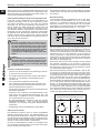
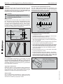
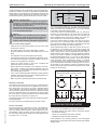
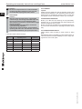
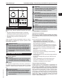
The mains frequency in Germany is 50 Hz. The voltage between two main conductors (L1L2L3) is the line-to-line voltage UL (voltage between phases, mains voltage). The voltage between a main conductor and the centre conductor is
the star voltage Uph (phase voltage). Here the following relation exists: UL = 1.73 x Uph.
U
L2
L3
U
Danger - rotating parts !
For bearings lubricated with grease for high temperatures, it can lead to a increased temperature
development in the first hour, until the grease and
the bearings have been run in.
Drive the fan slowly to the operating speed and
watch out for the vibrations at the bearing block
or at the pedestal bearings.
L1
EN
U
condition before the fan is electrically connected and started.
Check the condition of the clutch, especially the optimal flight.
Please refer to the manufacturer’s instructions. Start the fan
at low speed and pay attention to the behaviour of the clutch
and the bearings. Pay special attention for unusual noises.
UL UL
www.elektror.com
N
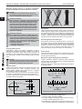
The three winding starts (U1, V1, W1) and winding ends
(U2, V2, W2) are fed to the six terminals in the terminal box.
There, the three main conductors (L1, L2, L3) are always
connected to the phase winding starts.
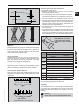
If the phase ends are joined together (U2, V2, W2), then
the motor is connected in star (Y). At the star point, the sum
of the voltages and currents is equal to zero, and here the
phase resistance lies on the phase voltage. The motor current corresponds to the current in the winding phase.
If the end of each phase is joined to the start of the next,
then the motor is connected in delta. The phase resistance
lies on the mains voltage. The motor current derives from the
geometric sum of two phase currents (Figure 2)
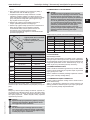
These relationships make it clear that a motor can be connected both in Y-connection (star) on the 400 V supply and
in delta-connection on the 230 V supply. Approximately the
same current flows in the winding phase in both cases. A
similar situation also applies for the new preferred voltages
of 690 V (Y) and 400 V (delta). If the alphabetic sequence of
the terminal designations (U1, V1, W1, U2, V2, W2) matches
the temporal sequence of the phases, the machine should
rotate clockwise. With anti-clockwise rotation, to external
connecting leads on the machine must be swapped. According to VDE 0530 the terminal box must also have a connecting terminal for the protective conductor. Machines with a
nominal power that exceeds 100 kW must also have an earth
terminal on the housing.
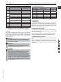
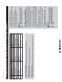
Winding designs 220 V / 380 V
direct power supply at operating voltage
380 V
220 V
W2
L1
U1
U1
L1
11
W1
L3
U2
U2
V2
W2
U1
V1
U2
V1
V2
L2
L2
V2
W1
L1
L2
L3
Δ-configuration
W2
V1 L2
U2
V2
U1
V1
W1
L1
L2
L3
Y-configuration
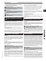
8 OPERATING THE VENTILATOR
The ventilator must be operated only by persons trained in
how to use it. The ventilator may only be used when:
• all safety devices and safety-critical monitoring devices
are fitted and working.
• nobody is in the danger area of the machine
• all inspection holes are safe and closed.
If the ventilator is not working properly, it must be stopped
straight away and secured in this state. Get the fault rectified
straight away!