1
Operating instructions
Betriebsanleitung
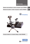
Pressure balance in compact design, model CPB3800
GB
Kolbenmanometer in Kompaktausführung, Typ CPB3800
D
Pressure balance in compact design, model CPB3800
GB Operating instructions model CPB3800
D Betriebsanleitung Typ CPB3800
Page
3 - 46
Seite
47 - 90
© 2013 WIKA Alexander Wiegand SE & Co. KG
All rights reserved. / Alle Rechte vorbehalten.
WIKA® is a registered trademark in various countries.
WIKA® ist eine geschützte Marke in verschiedenen Ländern.
Prior to starting any work, read the operating instructions!
Keep for later use!
14062232.02 04/2013 GB/D
Vor Beginn aller Arbeiten Betriebsanleitung lesen!
Zum späteren Gebrauch aufbewahren!
2
WIKA operating instructions model CPB3800
Contents
Contents
14062232.02 04/2013 GB/D
1.
2.
2.1
2.2
2.3
2.4
2.5
3.
4.
4.1
4.2
4.3
4.4
General information
Safety
Intended use
Personnel qualification
Personal protective equipment
Special hazards
Labelling, safety marks
Specifications
Design and function
Description
Scope of delivery
Base unit
Piston unit
4.5
Function
5.
Transport, packaging and storage
6.
Commissioning, operation
6.1
Unpacking the pressure balance
6.2
Environmental requirement
6.3
Assembly of base units
6.4
Assembly of piston unit
6.5
Assembly of the pressure balance
6.6
Procedure
6.7
Completion
6.8
Pressure calculation computer software standard accuracy program
6.9
Temperature measurement of piston units
6.10 Cleaning gauges
7.
Maintenance, cleaning and recalibration
7.1
Periodic maintenance
7.2
Corrective maintenance
7.3
Cleaning
7.4
Recalibration
8.
Faults
9.
Return and disposal
10.
Accessories
Appendix: EC Declaration of conformity for model CPB3800
4
6
6
7
7
8
10
11
20
20
20
20
22
23
24
25
25
25
25
26
27
28
31
31
32
32
34
34
34
38
38
41
43
44
45
Declarations of conformity can be found online at www.wika.com.
WIKA operating instructions model CPB3800
3
GB
1. General information
1. General information
■■ The model CPB3800 pressure balance in compact design described in the operating
instructions has been designed and manufactured using state-of-the-art technology.
All components are subject to stringent quality and environmental criteria during
production. Our management systems are certified to ISO 9001 and ISO 14001.
■■ These operating instructions contain important information on handling the
instrument. Working safely requires that all safety instructions and work instructions
are observed.
■■ Observe the relevant local accident prevention regulations and general safety
regulations for the instrument's range of use.
■■ The operating instructions are part of the product and must be kept in the immediate
vicinity of the instrument and readily accessible to skilled personnel at any time.
■■ Skilled personnel must have carefully read and understood the operating instructions
prior to beginning any work.
■■ The manufacturer's liability is void in the case of any damage caused by using
the product contrary to its intended use, non-compliance with these operating
instructions, assignment of insufficiently qualified skilled personnel or unauthorised
modifications to the instrument.
■■ The general terms and conditions contained in the sales documentation shall apply.
■■ DH-Budenberg Ltd/WIKA reserve the right to change the contents or form of these
operating instructions at any time without prior notice having been given.
■■ Subject to technical modifications.
■■ Factory calibrations or UKAS calibrations (pressure calibration with a mass set) are
carried out in accordance with international standards.
14062232.02 04/2013 GB/D
GB
4
WIKA operating instructions model CPB3800
1. General information
■■ Further information:
DH-Budenberg Ltd.
- Internet address:
- Relevant data sheet:
- Application consultant:
www.wika.de / www.wika.com
CT 31.06
Tel.:
(+44) 844 4060086
Fax:
(+44) 844 4060087
E-mail: [email protected]
GB
WIKA Alexander Wiegand SE & Co. KG
- Internet address:
www.wika.de / www.wika.com
- Relevant data sheet:
CT 31.06
- Application consultant:
Tel.:
(+49) 9372/132-0
Fax:
(+49) 9372/132-406
E-mail: [email protected]
Explanation of symbols
WARNING!
... indicates a potentially dangerous situation that can result in serious
injury or death, if not avoided.
CAUTION!
... indicates a potentially dangerous situation that can result in light
injuries or damage to equipment or the environment, if not avoided.
14062232.02 04/2013 GB/D
Information
... points out useful tips, recommendations and information for efficient
and trouble-free operation.
WIKA operating instructions model CPB3800
5
2. Safety
2. Safety
WARNING!
Before installation, commissioning and operation, ensure that the
appropriate pressure balance has been selected in terms of measuring
range, design and specific measuring conditions.
Non-observance can result in serious injury and/or damage to the
equipment.
GB
Further important safety instructions can be found in the individual
chapters of these operating instructions.
2.1 Intended use
Pressure balances are the most accurate instruments available on the market for the
calibration of electronic or mechanical pressure measuring instruments. By direct
measurement of the pressure as the quotient of force and area (p = F/A), pressure
balances are approved as primary standards.
The core component of the CPB3800 is therefore a very precisely-manufactured pistoncylinder system, which is loaded with masses in order to generate the individual test
points. The masses applied are proportional to the target pressure and this is achieved
through graduated masses. A maximum pressure of 1,200 bar must not be exceeded.
The pressure is set via an integrated, finely-adjustable, precision dual area spindle
pump. As soon as the measuring system reaches equilibrium, there is a balance of
forces between the pressure and the mass load applied.Then the test item can be
calibrated or adjustments can be carried out.
The instrument has been designed and built solely for the intended use described here,
and may only be used accordingly.
The technical specifications contained in these operating instructions must be
observed. Improper handling or operation of the instrument outside of its technical
specifications requires the instrument to be taken out of service immediately and
inspected by an authorised DH-Budenberg/WIKA service engineer.
6
WIKA operating instructions model CPB3800
14062232.02 04/2013 GB/D
Due to its stand-alone operation (integrated pressure generation and the pure
mechanical measuring principle), the model CPB3800 is ideal for on-site use for
maintenance and service.
2. Safety
Handle mechanical precision measuring instruments with the required care (protect
from humidity, impacts, strong magnetic fields, static electricity and extreme
temperatures, do not insert any objects into the instrument or its openings).
If the instrument is transported from a cold into a warm environment, the formation of
condensation may result in instrument malfunction. Before putting it back into operation,
wait for the instrument temperature and the room temperature to equalise.
The manufacturer shall not be liable for claims of any type based on operation contrary
to the intended use.
2.2 Personnel qualification
WARNING!
Risk of injury should qualification be insufficient!
Improper handling can result in considerable injury and damage to
equipment.
■■ The activities described in these operating instructions may only be
carried out by skilled personnel who have the qualifications described
below.
■■ Keep unqualified personnel away from hazardous areas.
Skilled personnel
Skilled personnel are understood to be personnel who, based on their technical training,
knowledge of measurement and control technology and on their experience and
knowledge of country-specific regulations, current standards and directives, are capable
of carrying out the work described and independently recognising potential hazards.
Special operating conditions require further appropriate knowledge, e.g. of aggressive
media.
14062232.02 04/2013 GB/D
DH-Budenebrg/WIKA can provide dedicated training courses on the correct use of our
products. Please contact your local office for further details.
2.3 Personal protective equipment (P.P.E.)
The personal protective equipment is designed to protect the skilled personnel from
hazards that could impair their safety or health during work. When carrying out the
various tasks on and with the instrument, the skilled personnel must wear personal
protective equipment.
WIKA operating instructions model CPB3800
7
GB
2. Safety
Follow the instructions, displayed in the work area, regarding personal
protective equipment!
The required personal protective equipment must be provided by the operating
company.
Wear safety goggles!
Protect eyes from flying particles and liquid splashes.
2.4 Special hazards
WARNING!
To ensure safe working on the instrument, the operating company must
ensure
■■ that suitable first-aid equipment is available and aid is provided
whenever required.
■■ that the operating personnel are regularly instructed in all topics
regarding work safety, first aid and environmental protection and
knows the operating instructions and, in particular, the safety
instructions contained therein.
WARNING!
Residual media at the pressure balance can result in a risk to persons,
the environment and the equipment. Take sufficient precautionary
measures.
2.4.1 Mineral oils health and safety information
DH-Budenberg/WIKA provide hydraulic mineral oil in 500 ml containers labelled "ISO
VG 22" for use up to 4,000 bar in pressure balances. It is no more hazardous than other
common lubricating oils.
It is the nature of the way in which this equipment is used, that there
could be frequent and/or prolonged skin contact; in a few individuals this
could give rise to skin irritation (Keratosis or Dermatitis). The use of an
effective barrier cream and/or protective gloves will greatly reduce this
possibility.
8
WIKA operating instructions model CPB3800
14062232.02 04/2013 GB/D
GB
2. Safety
Description
Closed flash point
greater than 120 °C
Storage
not above 30 °C
Oral LD 50
15 g per kg body weight
Threshold limit value
5 mg/m³
Fire extinguishing media
CO2/dry chemical foam or water fog
Spillage
Soak with absorbent clay or proprietary absorbent
Waste disposal
Burn or dump in approved area
GB
Emergency treatment of acute effects
Ingestion
Do not induce vomiting.
Administer 250 ml milk or olive oil.
The main hazard following accidental ingestion is aspiration
of liquid into lungs.
Aspiration
Send to hospital immediately
Inhalation
Remove to fresh air, if nausea persists seek medical attention.
Wash with copious amounts of water for at least 10 minutes.
If irritation results or persists, obtain medical advice.
Where skin rashes or other abnormalities occur as a result
of prolonged or repeated contact, medical advice should be
obtained as soon as possible.
Eye contact
Skin contact
2.4.2 Other liquids
For some very particular applications we supply specially constructed liquids. Copies of
manufacturer’s data can be sent on request.
14062232.02 04/2013 GB/D
2.4.3 Lifting of weights
WARNING!
Care must be taken when lifting the weights onto the pressure balance.
Each weight must be lifted individually and never attempt to lift stack of
weights on or off the pressure balance.
WIKA operating instructions model CPB3800
9
2. Safety
2.5 Labelling, safety marks
Product label
For an explanation of
symbols, see below.
Serial No.
Pressure range
Date of manufacture
Explanation of symbols
Before mounting and commissioning the instrument, ensure you read the
operating instructions!
CE, Communauté Européenne
Instruments bearing this mark comply with the relevant European
directives.
14062232.02 04/2013 GB/D
GB
10
WIKA operating instructions model CPB3800
3. Specifications
3. Specifications
Piston-cylinder systems
Measuring range 1)
Required masses
Smallest step 2)
(Standard mass set)
Nominal cross-sectional area of
the piston
Measuring range 1)
Required masses
Smallest step 2)
(Standard mass set)
Nominal cross-sectional area of
the piston
bar
kg
41
2.5 ... 300
50
5 ... 700
58
10 ... 1,200
50
bar
1
2.5
5
10
in²
1/16
1/40
1/80
1/160
lb/in² 10 … 1,600 25 ... 4,000 50 ... 10,000 100 ... 16,000
lb/in² 10
kg
47
25
50
100
in²
1/16
1/40
1/80
1/160
Accuracies
47
58
47
Standard 3) 4)
0.05 % of reading
Pressure transmission
medium
Hydraulic fluid based on VG22 mineral oil (0.5 l
included in scope of delivery)
0.025 % of reading
Option 3) 4)
Material
Piston
Tungsten carbide
Mass set
Stainless steel, non-magnetic
Cylinder
Weight
Piston-cylinder system
BAR mass set incl. overhang
(bell jar)
lb/in² mass set incl. overhang
(bell jar)
Carrying case for mass set
(optional, 2 pieces required)
Dimensions
14062232.02 04/2013 GB/D
1 … 120
Carrying case for mass set
(optional)
1)
2)
3)
4)
Tungsten carbide
kg
2.4
41.5
50.5
58.5
50.5
kg
47.5
47.5
58.5
47.5
kg
5.8
kg
400 x 310 x 310 mm (W x H x D) and
215 x 310 x 310 mm (W x H x D)
Theoretical starting value; corresponds to the pressure value generated by the piston or the piston and its make-up weights (by
their own weight). To optimise the operating characteristics more weights should be loaded.
The smallest pressure change value that can be achieved based on the standard weight set. To reduce this, a set of trim
masses is also available.
The accuracy from 10 % of the measuring range is based on the measured value. In the lower range, a fixed error based on
10 % of the range applies.
Measurement uncertainty assuming reference conditions (ambient temperature 20 °C, air pressure 1,013 mbar, relative humidity 40 %). For operation without a CalibratorUnit, corrections must be made if required.
WIKA operating instructions model CPB3800
11
GB
3. Specifications
Base
Connections
Connection for piston-cylinder
system
Test item connection
Material
G ¾ B (male)
G ½ female thread, loose union connection, incl. adapter set to
G ¼ and G ⅜ female threads
Wetted parts
Austenitic stainless steel, high tensile brass, nitrile rubber
Reservoir
170 cm³
Pressure transmission
medium
Hydraulic fluid based on VG22 mineral oil (0.5 l included in
scope of delivery)
Weight
Base
Storage case for the base
(optional)
13.5 kg
8.5 kg
Permissible ambient conditions
Operating temperature
Dimensions
Base
18 ... 28 °C
401 x 397 x 155 mm (W x D x H), for details, see technical
drawings
Approvals and certificates
CE conformity
Pressure equipment directive
Certificate
Calibration
97/23/EC (Module A)
Calibration certificate
Option: UKAS calibration certificate (pressure calibration with a
mass set)
For further specifications see WIKA data sheet CT 31.06 and the order documentation.
14062232.02 04/2013 GB/D
GB
12
WIKA operating instructions model CPB3800
3. Specifications
Tables of masses
The following tables show, for the respective measuring range, the number of masses
within a mass set, with their resulting nominal pressures.
Should the instrument not be operated under reference conditions (ambient temperature
20 °C, air pressure 1,013 mbar, relative humidity 40 %), relevant corrections must be
made.
The masses are manufactured, as standard, to standard gravity of 9.80665 m/s². As an
optional extra, mass sets can be manufactured for customer local gravity value.
Measuring range
[bar]
1 ... 120
Nominal
pressure per
piece
2,5 ... 300
Quan- Nominal
tity
pressure per
piece
1
1
1
20
1
1
2.5
50
3
20
3
50
1
1
2
1
1
20
10
4
2
1
1
1
2
1
1
50
25
10
5
2.5
Nominal
pressure per
piece
10 ... 1.200
Quan- Nominal
tity
pressure per
piece
1
1
5
100
1
1
10
200
4
100
3
200
1
100
1
200
2
20
2
40
Quantity
[bar]
Piston and make-up weight
Piston, overhang (bell jar) and
overhang make-up weight
Masses (stackable on overhang
(bell jar))
Masses (stackable on piston)
Measuring range
[bar]
5 ... 700
Quantity
14062232.02 04/2013 GB/D
[bar]
Piston and make-up weight
Piston, overhang (bell jar) and
overhang make-up weight
Masses (stackable on overhang
(bell jar))
Masses (stackable on piston)
1
1
1
WIKA operating instructions model CPB3800
50
10
5
[bar]
[bar]
1
1
1
100
20
10
13
GB
3. Specifications
GB
10 ... 1,600
Quantity
Nominal
pressure per
piece
[lb/in²]
25 ... 4,000
Quan- Nominal
tity
pressure per
piece
[lb/in²]
Piston
1
10
1
25
Overhang (bell jar) and overhang
make-up weight
1
190
1
475
Masses (stackable on overhang
(bell jar))
5
200
5
500
Masses (stackable on piston)
1
200
1
500
Measuring range
[lb/in²]
1
100
1
250
2
40
2
100
1
20
1
50
1
10
1
25
50 ... 10,000
Quantity
100 ... 16,000
Nominal
pressure per
piece
Quantity
[lb/in²]
Nominal
pressure per
piece
[lb/in²]
Piston
1
50
1
100
Overhang (bell jar) and overhang
make-up weight
1
950
1
1,900
Masses (stackable on overhang
(bell jar))
7
1,000
5
2,000
Masses (stackable on piston)
14
1
1,000
1
2,000
1
500
1
1,000
2
200
2
400
1
100
1
200
1
50
1
100
WIKA operating instructions model CPB3800
14062232.02 04/2013 GB/D
Measuring range
[lb/in²]
3. Specifications
Transport dimensions for complete instrument
The complete instrument, in its standard version and standard scope of delivery,
consists of three packages on a single pallet.
The dimensions are 1,200 x 800 x 500 mm.
The overall weight is dependant on the measuring range.
Version in bar
Weight in kg
net
gross
1 … 120 bar
71
89
5 … 700 bar
71
89
2.5 … 300 bar
10 … 1,200 bar
Version in lb/in²
71
71
Weight in kg
89
89
net
gross
10 ... 1,600 lb/in²
68
86
50 ... 10,000 lb/in²
68
86
25 ... 4,000 lb/in²
68
86
86
14062232.02 04/2013 GB/D
100 ... 16,000 lb/in²
68
GB
WIKA operating instructions model CPB3800
15
3. Specifications
Dimensions in mm
(without masses)
Front view
Side view
14062232.02 04/2013 GB/D
GB
16
WIKA operating instructions model CPB3800
3. Specifications
Top view
6
2
GB
7
5
3
8
1
4
(1) Test item connection
(2) High-pressure shut-off valve
(3) Low-pressure shut-off valve
(4) Dual-area spindle pump with star handle
(5) Piston-cylinder system
(6) Rotatable feet
14062232.02 04/2013 GB/D
(7) Reservoir with screwed sealing plug
(8) Pressure generation control schematic
WIKA operating instructions model CPB3800
17
3. Specifications
Standard connection piston-cylinder system
GB
O-ring 8.9 x 1.9
Oil collecting tray
Test item connection
Adapter, see scope
of delivery
Sealing ring
USIT 10.7 x 18 x 1.5
18
14062232.02 04/2013 GB/D
Oil collecting tray
WIKA operating instructions model CPB3800
3. Specifications
Liquids used
A hydraulic mineral oil viscosity 20 ... 37 cSt at 40 °C viscosity grade VG20 to VG37
to ISO 3448 (BS 4231) is used for the CPB3800 base unit. Most users will be able to
obtain locally suitable oil (see below) as used in hydraulic machinery. However, for the
convenience of users we can supply a 500 ml bottle of oil, viscosity grade VG22.
Oils suitable for pressure balances
The following oils are the commercially available oils suitable for use in the pressure
balance.
ISO 3448
viscosity
grade
VG22
VG32
VG37
Approx. SAE
viscosity
classification
10W
Shell
Tellus 22
Tellus R22
Tellus V32
DTE 24
Tellus 37
Tellus R37
Tellus T37
Tellus V37
Esso
Mobil
Nuto H22
DTE 22
Nuto H32
DTE Oil Light
Other liquids
The pressure balance model CPB3800 is manufactured for use on mineral oil only. If
an end user wishes to use it on another fluid, it is the end user responsibility to ensure
that the fluid is compatible with high tensile brass, stainless steel, mild steel, and nitrile
rubber, which are the materials that will come into contact with the fluid.
14062232.02 04/2013 GB/D
Fluids, which attack ABS, should be used with caution. Continual
immersion of the cover in such fluids will cause deterioration. Spillages
should be wiped off immediately.
Wear safety goggles!
Protect eyes from flying particles and liquid splashes.
WIKA operating instructions model CPB3800
19
GB
4. Design and function
4. Design and function
4.1 Description
The model CPB3800 pressure balance in compact design provides optimum features
for laboratory use whilst being rugged enough for industrial requirements. It provides a
highly accurate measurement of pressure.
The piston unit is screwed on to the left hand side pressure block of the base unit and
the test item is connected to the right hand pressure block.
4.2 Scope of delivery
■■ Base
■■ Dual-area spindle pump for filling, pressure generation and fine pressure adjustment
■■ Piston connection with G ¾ B male thread
■■ Test item connection with G ½ female thread, loose union connection
■■ Adapter set for test item connection, G ½ B male to G ¼ and G ⅜ female threads
■■ Piston-cylinder system with overhang (bell jar)
■■ Set of masses manufactured to standard gravity (9.80665 m/s²)
■■ VG22 mineral oil (0.5 litre)
■■ Tool and maintenance set consisting of:
1 hexagon wrench key 3 mm A/F
2 x 30 mm A/F open-ended spanners
1 spirit level
4 level plates
1 bag of seals
1 G ½ (½" BSP) angle connection
1 pointer press-on tool
1 pointer remover
1 test item connection
■■ Operating instructions in German and English language
■■ Factory calibration certificate
Cross-check scope of delivery with delivery note.
4.3 Base unit
The model CPB3800 series base unit consists of a solid aluminium base plate mounted
on four adjustable levelling feet, a screw pump, reservoir, control valves, pipework to
two stainless steel pressure connection blocks. The pipework and above mentioned
assemblies are covered by an easy to clean ABS cover.
20
WIKA operating instructions model CPB3800
14062232.02 04/2013 GB/D
GB
4. Design and function
Sectioned view of screw pump
G
C
F
D
14062232.02 04/2013 GB/D
E
J
H
K
GB
WIKA operating instructions model CPB3800
21
4. Design and function
4.3.2 Reservoir
A liquid reservoir is provided on the top of reservoir/high pressure cylinder block.
The reservoir is provided with a translucent cover to enable the reservoir level to be
monitored. A plug in the middle of the reservoir cover to allow the reservoir to be filled
or topped up (the plug is removed whilst the pressure balance is in use). The reservoir
contains enough liquid (approximately 150 cm³) to enable normal operation of the
pressure balance to be carried out.
Low pressure ram displacement = 60 cm³
High pressure ram displacement = 10 cm³
4.3.3 Control valves
Two control valves are provided on the top of reservoir/high pressure cylinder block.
The valve mechanisms are built into the reservoir/high pressure cylinder block and they
control the flow of liquid through internal drillings in the reservoir/high pressure cylinder
block. The rear valve is referred to as valve A and is used to control the output from the
larger diameter ram of the screw pump. The front valve is referred to as valve B and is
used to control the flow of liquid to and from the reservoir.
4.3.4 Connection blocks
Pressure supply pipes from the screw pump are terminated at two pressure blocks
mounted on the base unit. The pressure blocks are fitted with threaded bosses
projecting up through the cover plate of the base unit. These threaded bosses enable
piston units to be directly screwed on to them or connections for various sizes of gauge
connections to be screwed on to them. Oil cups are fitted to the unit cover around the
threaded bosses of the connection blocks to catch any oil drips from the gauge stand
during gauge fitting and removal.
4.4 Piston unit
The piston unit of the model CPB3800 is a single range piston unit, which covers the
range up to 1,200 bar (16,000 lb/in²).
22
WIKA operating instructions model CPB3800
14062232.02 04/2013 GB/D
GB
4.3.1 Screw pump
The screw pump is bolted to the reservoir/high pressure cylinder block fastened to the
base unit. A sectioned view of the pump is shown. The rotating handwheel (C) which
is operated by the spokes (D) is attached to a threaded spindle (E). The spindle is
supported in a sintered bearing (F). As the spindle (E) is rotated, it drives a non-rotating
ram (E and K) forward, the thrust being taken by a needle thrust bearing (G). The large
diameter of the ram (H) in the barrel of the pump (J) primes the pressure system and
provides the low pressure up to approximately 140 bar (2,000 lb/in²). The small diameter
of the ram (K) in the reservoir/ high pressure cylinder block provides the higher test
pressures up to 1,200 bar (16,000 lb/in2).
4. Design and function
Masses are loaded directly onto the piston head for low pressure calibration points. A
coloured band indicates when the piston is floating.
For higher pressure points, an overhang is fitted directly to the piston head, and weights
located at the bottom of the overhang or located on top of it. A machined groove on the
main piston body indicates when the piston is floating.
4.5 Function
Operation of the pressure balance is controlled by the two valves A and B on the top
of the reservoir/high pressure cylinder block. When initially priming the system valves
A and B are opened to fill the system with oil from the reservoir. Valve B is then closed
with valve A left open and the screw pump operated to provide the lower test pressures.
To provide the higher pressures valve A is closed to seal off the test circuit from the low
pressure part of the screw pump and valve B is opened to allow the liquid in the low
pressure part of the screw pump to return to the reservoir as the pump is operated. This
ensures that the pump can be operated without having to put large forces on the screw
pump handwheel. To release the test pressure the screw pump is wound out and valve
A is opened.
Valve A
14062232.02 04/2013 GB/D
Reservoir
Valve B
Hand pump
WIKA operating instructions model CPB3800
23
GB
5. Transport, packaging and storage
5. Transport, packaging and storage
5.1 Transport
Check model CPB3800 pressure balance for any damage that may have been caused
by transport.
Obvious damage must be reported immediately.
5.2 Packaging
Do not remove packaging until just before mounting.
Keep the packaging as it will provide optimum protection during transport (e.g. change
in installation site, sending for repair or recalibration).
Masses are shipped in cardboard and not in their respective wooden
cases, if ordered.
Wooden cases are not suitable for use as shipping cases.
5.3 Storage
Permissible conditions at the place of storage:
■■ Storage temperature: -10 ... +50 °C
■■ Humidity:35 ... 85 % relative humidity for instrument base and mass set
35 ... 65 % relative humidity for piston-cylinder unit (no condensation)
Avoid exposure to the following factors:
■■ Direct sunlight or proximity to hot objects
■■ Mechanical vibration, mechanical shock (putting it down hard)
■■ Soot, vapour, dust and corrosive gases
■■ Potentially explosive environments, flammable atmospheres
■■ Corrosive liquids
Store the model CPB3800 pressure balance in its original packaging in a location that
fulfils the conditions listed above. If the original packaging is not available, pack and
store the instrument as described below:
1. Wrap the instrument in an antistatic plastic film.
2. Place the instrument, along with shock-absorbent material, in the packaging.
3. If stored for a prolonged period of time (more than 30 days), place a bag, containing a
desiccant, inside the packaging.
24
WIKA operating instructions model CPB3800
14062232.02 04/2013 GB/D
GB
6. Commissioning, operation
6. Commissioning, operation
6.1 Unpacking the pressure balance
As soon as possible after delivery open the packaging of the system and check that
you have all the items detailed in the packing list (see chapter 4.2 “Scope of delivery”).
As you are unpacking the items, examine them for signs of damage or breakage during
transit.
If any items are missing get in touch immediately with DH-Budenberg/WIKA to inform us
of the shortage.
6.2 Environmental requirement
When siting the pressure balance if not in a temperature controlled laboratory look for
an area that satisfies the following criteria as much as possible:
■■ A constant temperature area free from draughts and sources of heat or cold
■■ An area free from noise and vibration, constantly used pathways
■■ A clean dry area free from corrosive liquids or vapours
A strong, stable, level table or workbench with the capability of supporting the system
with sufficient space to operate is required.
6.3 Assembly of base units
Fastening base to bench
The base is to be mounted on a firm, level table or bench about 0.9 m high. The centre
line of the front adjustable feet of the unit should be about 40 mm from the front edge of
the bench to allow adequate clearance for the handwheel.
1. Mark the position of the adjustable feet of the unit on the top of the bench.
2. Position a level plate at the centre of each of the adjustable feet of the unit and screw
the plate to the bench to ensure that the pressure balance is rigid.
14062232.02 04/2013 GB/D
3. Fit the base unit on the bench with the adjustable feet on the level plates and the
handwheel shaft projecting over the front of the bench.
4. Screw in the four handwheel spokes into the hub.
5. Using the spirit level provided, level the unit in both the front/rear axis and the side
to side axis by adjusting the four knurled feet, by placing the spirit level on top of the
piston-cylinder unit.
WIKA operating instructions model CPB3800
25
GB
6. Commissioning, operation
1. Unscrew the knurled retaining cap from the main body.
2. Place the piston head on a flat surface, with the piston facing vertically.
3. Fit the knurled retaining cap to the piston via the eccentric hole.
4. Place the main piston body with the external thread in a vertical position.
5. Lubricate the piston with the pressure medium, and insert the piston into the cylinder
in the main body in a vertical direction only.
WARNING!
Do not apply any transverse force. Excess force is not required.
6. Tighten the knurled retaining cap to the main body.
7. Lift the piston head until it engages against its internal stop. This movement should
be free.
Overhang
Main body
Piston head
14062232.02 04/2013 GB/D
GB
6.4 Assembly of piston unit
The piston unit of the CPB3800 has its own transportation box that should be used for
storing the unit when not in operation, and if the customer ever has to send the unit
back for recalibration. The following details show how the piston is to be assembled/
disassembled to the main body.
26
WIKA operating instructions model CPB3800
6. Commissioning, operation
6.5 Assembly of the pressure balance
1. Fit the piston unit to the left hand connection. Ensure that the mating faces are clean
and the 12 mm diameter O-ring seal correctly located. Excess force is not required
to achieve an effective seal.
2. Check the level of the system base with the spirit level on the piston-cylinder
unit. Level if necessary by using the levelling screws. If using as a comparator, fit
additional loose union connection (order number 14031251) to port that piston unit
would be fitted to.
3. Fit the appropriate connection to the gauge stand, using a bonded seal to make the
joint and screw a test gauge (for installation use a known gauge) into position, also
with a bonded seal.
If preferred, a copper or leather washer can be substituted for the bonded seal at
the gauge. The loose nut on the pressure balance base enables the gauge to be
positioned as required and for back connection gauges the angle connection is
screwed into the loose union connection.
6.5.1 Filling the base unit with liquid
1. Remove filler plug from reservoir by prising plug out. (This plug should be left out
whilst in use).
2. Open valves A and B.
3. Wind screw pump handle fully clockwise.
4. Fill reservoir with appropriate liquid. Use the oil supplied or an approved substitute
for oil systems. Do not use other liquids. Castor based oils, Skydrol, solvents or
similar liquids will attack the seals fitted in the pressure balance.
5. Wind screw pump handle fully anti-clockwise.
6. Top up reservoir if necessary.
14062232.02 04/2013 GB/D
Wear safety goggles!
Protect eyes from flying particles and liquid splashes.
6.5.2 Post assembly test
1. Carry out a test calibration of a known instrument (see chapter 6.6 "Procedure") to
ensure that the unit is working correctly.
WIKA operating instructions model CPB3800
27
GB
6. Commissioning, operation
2. Release the pressure and remove the test instrument.
To remove the instrument from the system, use the appropriate size
of spanners on the top section of the pressure connection and on the
body of the instrument only. Ensure that the lower part of the pressure
connection is not rotated as this may release it from the base.
GB
3. The system is now ready for use.
CAUTION!
If the volume required to be filled is very large requiring the use of an
additional pump and reservoir to be connected to the model CPB3800,
it is ESSENTIAL to ensure that valve B is kept open and valve A closed
at all times otherwise a high pressure can be built up on the low pressure
ram of the screw press and damage caused. To ensure this does not
happen we can supply the system fitted with a relief valve, which will
release at a set pressure, should the valve operation be incorrect.
Alternatively, we can supply a modified system and hand pump for this
operation. For further information on both items contact DH-Budenberg/
WIKA.
When testing equipment with a large volume, the capacity of the screw
pump (65 cm³) may be insufficient to reach the pressure required. In this
case, the equipment should be filled as far as possible with the liquid
before connecting it to the system, so that the displacement needed is
reduced.
Wear safety goggles!
Protect eyes from flying particles and liquid splashes.
6.6 Procedure
1. Fit instrument to be tested to gauge stand.
28
WIKA operating instructions model CPB3800
14062232.02 04/2013 GB/D
Dirty or chemically contaminated test items should not be fitted as they
contaminate the system unless they are first cleaned.
6. Commissioning, operation
2. Load the weights equivalent to the desired pressure. Each weight is marked with its
pressure value. The piston-cylinder unit has a basic lb/in² start, for other pressure
units a make-up weight is added to the piston head for conversion to bar.
For calibrating pressures less than the pressure value of the overhang
make-up weight value, it is recommended that the top loading weights
are used for calibration. When the required pressure calibration unit is
bar, it is essential that the small make-up weight is fitted first before any
other top loading weights.
For calibrating pressures greater than the pressure value overhang
make-up weight value, the overhang should be fitted. All top loading
weights must be removed before fitting the overhang.
When the overhang is fitted, the initial weight that goes onto it is a large
annular make-up weight. The small type make-up weight should not be
used when the overhang is fitted.
6.6.1 To apply pressure
For pressures up to 140 bar (2,000lb/in²)
1. Close valve B (valve A remaining open).
2. Wind screw pump handle clockwise. This will generate pressure up to approximately
140 bar or 2,000 lb/in², as handle is wound in. When handle becomes stiff to rotate
this will indicate that the pressure limit for this range has been reached.
For pressures above 140 bar (2,000lb/in²)
1. Ensure valve B closed and valve A open.
2. Wind screw pump handle clockwise until the handle becomes stiff to operate.
14062232.02 04/2013 GB/D
3. Close Valve A and open valve B.
4. Continue to wind screw pump handle clockwise. This will generate pressure up to
approximately 1,200 bar or 16,000 lb/in².
5. When the piston rises and appears to floats, this indicates it is at its nominal desired
pressure. When only top loading weights are being utilised, a blue and yellow band
indicates the float position. When the overhang is being employed, the bottom of
the overhang will line up with a machined groove in the piston holders main body, to
indicate its nominal desired pressure.
WIKA operating instructions model CPB3800
29
GB
6. Commissioning, operation
During calibration, the weights should be rotated by hand. It is desirable that the weights
should only be rotated when approximately the correct pressure is obtained. Weights
should not be brought to rest by fully releasing the pressure and allowing the piston
head to rotate against its stop under the full load of the weight pile.
It is essential that the weights spin freely during readings. The piston stops moving when
the pressure is too high or too low. At the lowest pressures the weights will not spin
for more than a few seconds unless a very thin oil is used, but providing the weight is
rotated by hand before taking a reading and is obviously "floating" an accurate reading
will be given.
CAUTION!
Care should be exercised at all times when rotating the weights. Failure
to do so may cause damage to the actual piston unit, or possibly injury to
the operator.
Therefore, the rotational motion should be stopped by hand. Only then
new masses for further test points can be placed or the pressure can be
released completely.
6.6.3 Datum levels
When testing gauges on liquid it is occasionally necessary to take into account heads
of liquid since a height difference of 10 mm corresponds to approximately 1 mbar. The
datum levels of the models CPB3800 piston units are marked with a groove on the
outer diameter of the piston unit. It should be noted that when the pressure balance is
re-calibrated by a laboratory other than DH-Budenberg/WIKA, the datum level at which
the tests have been carried out may differ from this standard and therefore allowance
should be made for any variation.
The drawing shows the head effect that may have to be compensated for when high
accuracy calibration is desired. The following formula will enable the head correction to
be calculated.
30
WIKA operating instructions model CPB3800
14062232.02 04/2013 GB/D
GB
6.6.2 During calibration
When the pressure balance is correctly set up and there are no leaks the piston should
"float" for many minutes without it being necessary to touch the screw pump handwheel.
On the initial setting up, however, there may be some air trapped in the base of the
piston/cylinder unit. As this leaks past the piston the weights may fall slightly but it will
only be for a matter of a few minutes until the air has escaped. If the piston continues to
fall, check the connections for leaks.
6. Commissioning, operation
▲P due to head effects
Pressure (Pa)
Where
σ
H
g
Density of VG 22 oil
= σ•H•g
=
=
=
=
GB
density (kg/m²)
height (in metres)
gravity (m/s²)
885 kg/cm²
Cylinder datum
Zero buoyancy datum
6.7 Completion
1. After the test is finished wind screw pump handle anti-clockwise to lower pressure.
2. Gently open valve A or B to release residual pressure.
3. Ensure that both valves A and B are fully open.
14062232.02 04/2013 GB/D
The system is now ready for another test and any residual pressure is relieved.
6.8 Pressure calculation computer software standard accuracy program
This software enables the user to define his equipment and local conditions (gravity,
temperature), so that when nominal pressures are entered, actual achieved pressures
are displayed
These actual pressures will then be to the standard accuracy of the pressure balance.
To achieve the improved standard accuracy the user must enter the correction factor
given on the improved accuracy certificate supplied with the piston unit.
WIKA operating instructions model CPB3800
31
6. Commissioning, operation
Default conditions are input at DH-Budenberg/WIKA but once the user alters these, his
values then become the default (no need to repeatedly insert your values).
GB
This program has been written to aid users to maintain the standard
accuracy of DH-Budenberg/WIKA pressure balance. It has not been
written for use with any other makes of pressure balance.
The software can be accessed from the supplied CD in the folder "Customer Software"
and "Standard Accuracy DWT". Installation/Operating instructions should be read
before using the software.
6.9 Temperature measurement of piston units
For many purposes, such as calibrating most type of dial gauges and transducers,
accurate knowledge of the temperature of a piston unit is not necessary. However, in
order to achieve the utmost accuracy from a pressure balance it is important to know the
temperature of the piston unit as close as possible to the working part of the unit.
In laboratories where the room temperature is controlled it is most likely that the
temperature of the working parts of the unit will not differ from the ambient temperature
by more than 0.5 °C. When working in uncontrolled temperatures, however, one would
have to measure the temperature of the piston unit.
A possible way to do this is to use a disc shaped thermistor type probe sensing element
taped to the outer surface of the piston unit. The sensing element should be insulated
from the ambient temperature by covering the element with a thin strip of polystyrene,
or other insulating material, then taping this to the piston unit. Alternatively, a model
CPU5000 may be used.
6.10 Cleaning gauges
This cleaning/degreasing process is only suitable for use with pressure gauges with
either phosphor bronze, beryllium copper, monel or stainless steel bourdon tubes in the
form of a "C".
It is not advisable to degrease pressure gauges with steel bourdon tubes since a very
small amount of corrosion on the bore of a bourdon tube can cause inaccuracies of
reading and early failure of the tube.
32
WIKA operating instructions model CPB3800
14062232.02 04/2013 GB/D
We can supply a suitable instrument. Please contact DH-Budenberg/WIKA.
6. Commissioning, operation
Wear safety goggles!
Protect eyes from flying particles and liquid splashes.
GB
This method of cleaning is not suitable for use with pressure gauges which are fitted
with coiled bourdon tubes, nor any gauges which are to be used on oxygen, as
complete removal of oil is not assured. Please contact DH-Budenberg/WIKA.
Equipment
This consists of a syringe and a special needle with the point bent through 90°.
Instructions
1. Fill syringe with solvent (suitable cold degreasing liquid).
2. With gauge connection pointing upwards put needle into connection and insert by
feel the point into the hole leading to the tube.
3. Inject the solvent. Ideally the tube should be half full.
4. Shake gauge in various attitudes to agitate solvent.
5. Suck solvent back into syringe, holding gauge at an angle.
6. Check that solvent removed is clean. To be sure that all oil has been removed,
repeat cleaning process until solvent removed from gauge is as clean as that put in.
Removing the
solvent
14062232.02 04/2013 GB/D
Filling with
solvent
Cleaning of gauges
WIKA operating instructions model CPB3800
33
7. Maintenance, cleaning and recalibration
7. Maintenance, cleaning and recalibration
7.1 Periodic maintenance
Repairs must only be carried out by the manufacturer.
Cleaning the units and checking the liquid levels is the only periodic maintenance
required. With normal use, no further maintenance should be necessary. If required, the
system can be returned to the manufacturer for re-conditioning. Accuracy, overhaul and
re-certification are also explained in chapter 7.4.1 "Factory overhaul and re-certification
of pressure balances maintenance of accuracy".
Fluids, which attack ABS, should be used with caution. Continual
immersion of the cover in such fluids will cause deterioration. Spillage’s
should be wiped off immediately.
7.2 Corrective maintenance
7.2.1 General
This section contains details on stripping the unit and replacing the spare parts which
are listed (see chapter 10 "Accessories"). The component identification numbers in
brackets in each procedure refer to the following figure.
7.2.2 Removing the cover
1. Drain as much oil as possible from the pressure balance by winding the screwpress
fully clockwise and using a drain screwed in the gauge stand.
2. Unscrew the loose union connection and piston-cylinder unit.
3. Remove the oil cups by levering upwards carefully.
4. Slacken the socket set screw using a 3 mm hexagon wrench key and remove both
handwheels.
5. Remove the four cover retaining screws and lift off the cover.
7.2.3 Reservoir seals
1. Unscrew two screws and remove the reservoir cover
2. Remove the O-ring seal (6) from the recess and the seloc seal (7) from the screws.
3. On replacement ensure all sealing faces are absolutely clean and do not overtighten
screws.
34
WIKA operating instructions model CPB3800
14062232.02 04/2013 GB/D
GB
9
10
7. Maintenance, cleaning and recalibration
16
3
1
2
14062232.02 04/2013 GB/D
4
15
5
14
6
13
12
7
11
8
GB
WIKA operating instructions model CPB3800
35
7. Maintenance, cleaning and recalibration
7.2.4 Valve seals
2. Unscrew the valve spindle and remove the bonded seal.
3. Slide gland nut off spindle.
4. Using a suitable hooked tool remove the O-ring seal (9) from the bore of the gland
nut. Renew O-ring and bonded seal (10).
5. On replacement ensure that O-ring is correctly located in the groove and all sealing
faces are clean. Remove all burrs from spindle.
7.2.5 Screw pump
1. Using a 4mm hexagon wrench key unscrew the six socket head cap screws securing the hub locating plate. (These are positioned inside the recess in the back of the
aluminium hub).
2. By carefully pulling the hub the complete ram assembly can now be withdrawn from
the barrel (During this operation a container is required beneath the barrel to catch
any liquid).
3. Unscrew the ram from the hub assembly.
4. The high pressure seal (12) and low pressure seal (15) can now be replaced. Before
fitting the new seals check the ram is not scored on the locating diameters.
5. At this point the hub assembly should be checked for excess play indicating wear in
the bearing and for wear in the screwed spindle and nut. If any wear is found it will be
necessary to dismantle the hub assembly.
6. Check the bore of the block assembly (11) is not badly scored or pitted. If a replacement is required this item is supplied complete with valves. The block is attached to
the base by socket head cap screws.
7. Re-assembly is a straightforward reversal of the above procedures.
On assembly care should be taken to align the ram to prevent bending,
or damage to the seals. Excessive force should not be used.
The socket head cap screws are not spaced equally around the locating
flanges so check hole alignment before inserting screws.
36
WIKA operating instructions model CPB3800
14062232.02 04/2013 GB/D
GB
1. Unscrew the gland nut.
7. Maintenance, cleaning and recalibration
7.2.6 Hub assembly
1. Unscrew the ram from the spindle. NOTE: left hand thread.
2. Unscrew the spokes from the hub.
3. Knock out the spring pin (1), found at the bottom of one of the tapped spoke holes in
the hub, using a punch 6 mm dia. Pull off hub.
4. The hub locating plate and thrust bearing can now be removed from the spindle.
5. If the flanged bush (2) is to be renewed, it should be pressed out of the locating
plate and a new one pressed in squarely.
6. The thrust bearing (3) is renewed as a complete assembly.
7. The nut, pin and spindle sub-assembly (4) can only be replaced as a matched pair.
Unscrew the nut from the ram, gripping in a soft jaw vice and screw in the new nut.
8. Assemble the thrust bearing, locating plate and hub on to the spindle, lubricating
with molybdenum disulphide grease.
9. Clamp these items together to eliminate end play and re-assemble spring pin. If
using new spindle drill through 6.3 mm diameter to fit spring pin (1).
10. Lubricate the thread with molybdenum disulphide grease and screw into ram nut.
7.2.7 Piston-cylinder unit
As the piston-cylinder unit represents a high proportion of the total value of the pressure
balance, it should always be handled with care and every effort made to keep it clean.
The piston-cylinder unit is made to extremely fine limits of accuracy and it is not
advisable to dismantle it. If it is necessary to clean it, the piston and cylinder bore must
be oiled immediately, in order to protect the high grade finish.
14062232.02 04/2013 GB/D
Should the unit become damaged it should be returned complete for replacement or
repair. Parts from different units are not interchangeable as they have to be weighed and
evaluated as a whole.
The serial number of the piston-cylinder unit appears in the certificate of accuracy and
is marked on the body of the unit. This number, as well as the pressure balance serial
number should always be quoted in correspondence concerning the piston/cylinder unit.
The piston-cylinder connections should be blanked if it is removed from the pressure
balance. If the unit is taken off for any reason it should be stored upside-down, resting
on its weight carrier.
WIKA operating instructions model CPB3800
37
GB
7. Maintenance, cleaning and recalibration
This covers stripping the unit to enable simple repairs and the fitting of recommended
spare parts to be carried out.
7.3 Cleaning
Cleaning the unit and checking the liquid levels.
Oil operation
Keep the system clean and free from spilt oil. Wipe out the oil cups under the gauge
stands as necessary. Do not use any cleansing solvents as they may damage the seals.
Ensure that the reservoir contains sufficient liquid to carry out any calibrations required.
If necessary top up the reservoir with the same liquid that is already being used. Do not
mix various types or brands of liquid in the pressure balance.
If the oil in the system becomes dirty, use the screw pump to flush through the clean oil
with a drain screwed in the gauge stand. (An angle connection is suitable). The screw
pump should be turned fully clockwise before starting.
Wear safety goggles!
Protect eyes from flying particles and liquid splashes.
For information on returning the instrument see chapter 9.1 "Return".
7.4 Recalibration
UKAS, DKD/DAkkS certificate - Certificates:
We recommend that the instrument is regularly recalibrated by the manufacturer, with
time intervals of 5 years. The basic settings will be corrected if necessary.
7.4.1 Factory overhaul and re-certification of pressure balances maintenance of
accuracy.
The accuracy of a pressure balance depends primarily on the effective area of the
piston unit and on the weights applied to the piston. The effective area of the piston unit
can be affected by wear of the unit. This is generally caused by contamination of the oil
in the pressure balance by foreign matter from instruments being calibrated, by water, or
by chemicals from instruments, or by rust or corrosion caused by contaminants.
38
WIKA operating instructions model CPB3800
14062232.02 04/2013 GB/D
GB
7. Maintenance, cleaning and recalibration
Weights are made of austenitic stainless steel which are entirely stable. They should be
periodically cleaned using a non abrasive method to remove any foreign matter.
GB
7.4.2 Need for overhaul and re-certification
We recommend that the pressure balance be returned to us for overhaul and
re-certification at any time if when used in accordance with instructions:
1. The piston does not spin freely.
2. The rate of fall of the piston is appreciably greater than when new and makes use of
the pressure balance difficult.
3. The weights are damaged.
4. The pressure balance cannot be made to operate satisfactorily due to wear or
damage to pump piping or valves which cannot be rectified by the user.
This pressure balance can be used for calibration of instruments with an expected
accuracy of 1, 0.5 or 0.25 %. Such pressure balances need not be sent back frequently
for overhaul and re-certification and provided they are working well can be trusted for
many years. Under these circumstances, an interval of five years might be appropriate
between overhauls.
When high accuracy of the pressure balances is required, it should be returned for
overhaul and re-certification more frequently. The actual period will depend on how the
pressure balance is used. A pressure balance kept in a laboratory and carefully used
might need to be returned every two to five years. A pressure balance carried from site
to site and used for calibrating high accuracy gauges or transducers from industrial
process plant or for measuring pressures directly might well need to be returned at
intervals of less than specified above.
14062232.02 04/2013 GB/D
The actual period between overhaul and re-certification should be fixed by the user in
the light of the above comments taking into account the requirements of any inspection
authority, which might be involved.
7.4.3 Identification of weights
All weight sets supplied with a pressure balance have allocated, and are marked, with
a weight set number. Additionally, if users wish to ensure that only specific weights are
used with an individual pressure balance or piston and cylinder unit, then the serial
number of the pressure balance, and/or piston-cylinder unit may also be marked on the
main weights. Regrettably due to size of certain weights, not all the above information
may be marked.
WIKA operating instructions model CPB3800
39
7. Maintenance, cleaning and recalibration
Pressure balance bases will be stripped, all pipework cleaned, all seals replaced, worn
components replaced where desirable, and all reassembled and tested.
The weights will all be checked and brought to within original limits if possible. If one or
two weights are missing or beyond economical repair they will be replaced. If more are
missing/ beyond economical repair customer instructions will be sought.
The piston unit will be checked for accuracy and sensitivity. If it is not satisfactory for any
reason a quotation will be submitted for a replacement unit.
A new certificate of accuracy will be issued for each overhauled pressure balance.
Unless otherwise instructed on order when there has been a slight change in area of
the piston unit the certificate will reflect this; the accuracy will not be affected by more
than 0.03 %. For example the certificate of accuracy of an overhauled pressure balance
might show that the error does not exceed 0.05 % when the original certificate shows
that the error did not exceed 0.02 %.
We can issue an UKAS or DKD/DAkkS certificate of calibration for an overhauled
system. Details will be supplied on request.
14062232.02 04/2013 GB/D
GB
7.4.4 Overhaul and re-certification
To provide the best possible service, the pressure balance should be returned as
complete units comprising the base, the piston and cylinder unit, and all the weights.
The base can also be serviced itself. The piston-cylinder unit with weights has to be sent
back for overhaul. In such instances, certification issued after overhaul can only refer to
the piston and cylinder and weight set numbers and not to the base to which they were
originally fitted.
40
WIKA operating instructions model CPB3800
8. Faults
8. Faults
Faults
Equipment does not
provide any output
pressure.
14062232.02 04/2013 GB/D
Equipment provides
pressure but pressure
decays to zero
Causes
Measures
No liquid in pressure balance.
Check that pressure balance is
filled with liquid. Fill the equipment
with fluid as necessary. See chapter 6.5.1 "Filling the equipment
with liquid".
Valve B is open.
Close valve B and try again.
Component being tested has a
large volume.
Pre-fill component with liquid
before test.
Missing or damaged liquid seals
shown by signs of unexplained
liquid leaks.
Examine seals on equipment to
ensure they are fitted correctly
and are undamaged. Replace as
necessary.
Valve B handwheel disconnected
from spindle.
Examine valve B. Tighten up nut
securing handwheel to spindle as
necessary.
Valve B assembly or valve seat
damaged.
Examine condition of valve B and
valve seat. Replace valve assembly or return pressure balance to
DH-Budenberg/WIKA for overhaul
as necessary.
If unable to locate a cause.
Return pressure balance to DHBudenberg/WIKA for investigation.
Incorrect operating procedure
being used.
Ensure that correct operating
procedure is being followed (see
chapter 6.6).
Missing or damaged liquid seals
shown by signs of unexplained
liquid leaks.
Examine seals on equipment to
ensure they are fitted correctly
and are undamaged. Replace as
necessary.
Valve A or Valve B valve assembly
or valve seat damaged.
Examine condition of valves A and
B and valve seat. Replace valve
assembly or return pressure balance to DH-Budenberg/WIKA for
overhaul as necessary.
If unable to locate a cause.
Return pressure balance to DHBudenberg/WIKA for investigation.
WIKA operating instructions model CPB3800
41
GB
8. Faults
GB
Equipment provides
pressure but pressure
decays when valves A
and B are operated.
Causes
Measures
Incorrect operating procedure
being used.
Ensure that correct operating
procedure is being followed (see
chapter 6.6).
If unable to locate a cause.
Return pressure balance to DHBudenberg/WIKA for investigation.
Insufficient liquid in pressure balance.
Check liquid level in reservoir. Fill
reservoir with correct liquid as
necessary (see chapter 6.5.1).
Air in the system
Prefill component under test with
appropriate liquid. If necessary refill pressure balance with appropriate liquid.
If unable to locate a cause.
Return pressure balance to DHBudenberg/WIKA for investigation.
Internal damage
Return pressure balance to DHBudenberg/WIKA for investigation.
Incorrect operating procedure
being used.
Ensure that correct operating
procedure is being followed (see
chapter 6.6).
If unable to locate a cause.
Return pressure balance to DHBudenberg/WIKA for investigation.
Pressure balance
screw press becomes
very stiff to operate
when pressure
balance is being
used in range below
140 bar (2,000 lb/in²)
Internal damage
Return pressure balance to DHBudenberg/WIKA for investigation.
Pressure balance
screw press becomes
very stiff to operate
when pressure balance
is being used in
range above 140 bar
(2,000 lb/in²)
Incorrect operating procedure
being used.
Ensure that correct operating
procedure is being followed (see
chapter 6.6).
If unable to locate a cause.
Return pressure balance to DHBudenberg/WIKA for investigation.
Equipment provides
pressure but pressure
decays to lower value
then remains steady.
42
WIKA operating instructions model CPB3800
14062232.02 04/2013 GB/D
Faults
8. Faults / 9. Return and disposal
CAUTION!
If faults cannot be eliminated by means of the measures listed above,
the pressure balance must be shut down immediately, and it must be
ensured that pressure is no longer present, and it must be prevented
from being inadvertently put back into service.
In this case, contact the manufacturer.
If a return is needed, please follow the instructions given in chapter
9.1 "Return".
GB
9. Return and disposal
WARNING!
Residual media at the pressure balance can result in a risk to persons,
the environment and equipment. Take sufficient precautionary measures.
9.1 Return
WARNING!
Strictly observe the following when shipping the instrument:
All instruments delivered to DH-Budenberg/WIKA must be free from any
kind of hazardous substances (acids, bases, solutions etc.).
14062232.02 04/2013 GB/D
When returning the instrument, use the original packaging or a suitable transport
package.
To avoid damage:
1. Place the piston-cylinder unit into the designed transport box (see chapter
6.4 „Assembly of piston unit“).
2. Wrap the instrument in an antistatic plastic film.
3. Place the instrument, along with the shock-absorbent material, in the packaging.
Place shock-absorbent material evenly on all sides of the transport packaging.
4. If possible, place a bag, containing a desiccant, inside the packaging.
5. Label the shipment as transport of a highly sensitive measuring instrument.
Information on returns can be found under the heading "Service" on our
local website.
WIKA operating instructions model CPB3800
43
9. Return and disposal / 10. Accessories
This marking on the instruments indicates that they must not be
disposed of in domestic waste. The disposal is carried out by return to
the manufacturer or by the corresponding municipal authorities (see EU
directive 2002/96/EC).
10. Accessories
Description/Features
Order no.
Set of trim-masses (1 mg up to 50 g), class F1
7093874
Set of 2 carrying cases for set of masses
14031236
Set of trim-masses (1 mg up to 50 g), class M1
Storage case for CPB3800 Instrument base
“BSP” adapter set for G ½ B male test item connector to G ⅛, G ¼,
G ⅜ and G ½ female
14025325
14031237
14031238
"NPT" adapter set for G ½ B male test item connector to ⅛ NPT,
¼ NPT, ⅜ NPT and ½ NPT female
14031239
Test item connection, G ¾ female to G ½ female, loose union
14031251
"Metric" adapter set for G ½ B male test item connector to M12 x 1.5
and M20 x 1.5 female
14031242
90° angle connection, for test items with back mounting connection
1564838
Separator (to separate two liquid media by a diaphragm), max. 700 bar 14031253
Separator (to separate two liquid media by a diaphragm),
max. 1,200 bar
14031254
Operating fluid for CPB series up to a max. 4,000 bar, 0.5 litre
2099954
Sealing set for CPB3800 instrument base
14031255
Tool set consists of open-ended spanner, BSP adapter, replacement
seals, pointer removal device and pointer press-on tool
14031263
44
WIKA operating instructions model CPB3800
14062232.02 04/2013 GB/D
GB
9.2 Disposal
Incorrect disposal can put the environment at risk.
Dispose of instrument components and packaging materials in an environmentally
compatible way and in accordance with the country-specific waste disposal regulations.
Appendix: EC Declaration of conformity for model CPB3800
14062232.02 04/2013 GB/D
GB
WIKA operating instructions model CPB3800
45
14062232.02 04/2013 GB/D
GB
46
WIKA operating instructions model CPB3800
Inhalt
Inhalt
14062232.02 04/2013 GB/D
1.
2.
2.1
2.2
2.3
2.4
2.5
3.
4.
4.1
4.2
4.3
4.4
Allgemeines
Sicherheit
Bestimmungsgemäße Verwendung
Personalqualifikation
Persönliche Schutzausrüstung
Besondere Gefahren
Beschilderung, Sicherheitskennzeichnungen
Technische Daten
Aufbau und Funktion
Beschreibung
Lieferumfang
Basement
Kolbeneinheit
4.5
Funktionen
5.
Transport, Verpackung und Lagerung
6.
Inbetriebnahme, Betrieb
6.1
Auspacken des Kolbenmanometers
6.2
Umgebungsbedingungen
6.3
Aufstellen des Basements
6.4
Zusammenbau der Kolbeneinheit
6.5
Zusammenbau des Kolbenmanometers
6.6
Vorgehensweise
6.7
Abschlussarbeiten
6.8
Druckberechnungssoftware Standardgenauigkeit
6.9
Kolbentemperaturmessung
6.10 Reinigung der Messgeräte
7.
Wartung, Reinigung und Rekalibrierung
7.1
Periodische Wartung
7.2
Instandhaltung
7.3
Reinigung
7.4
Rekalibrierung
8.
Störungen
9.
Rücksendung und Entsorgung
10.
Zubehör
Anlage: EG-Konformitätserklärung Typ CPB3800
48
50
50
51
51
52
54
55
64
64
64
64
66
67
68
69
69
69
69
70
71
72
75
76
76
77
78
78
80
83
83
86
88
89
90
Konformitätserklärungen finden Sie online unter www.wika.de.
WIKA Betriebsanleitung Typ CPB3800
47
D
1. Allgemeines
1. Allgemeines
■■ Das in der Betriebsanleitung beschriebene Kolbenmanometer in Kompaktausführung
■■ Diese Betriebsanleitung gibt wichtige Hinweise zum Umgang mit dem Gerät. Voraus-
setzung für sicheres Arbeiten ist die Einhaltung aller angegebenen Sicherheitshinweise und Handlungsanweisungen.
■■ Die für den Einsatzbereich des Gerätes geltenden örtlichen Unfallverhütungsvor-
schriften und allgemeinen Sicherheitsbestimmungen einhalten.
■■ Die Betriebsanleitung ist Produktbestandteil und muss in unmittelbarer Nähe des
Gerätes für das Fachpersonal jederzeit zugänglich aufbewahrt werden.
■■ Das Fachpersonal muss die Betriebsanleitung vor Beginn aller Arbeiten sorgfältig
durchgelesen und verstanden haben.
■■ Die Haftung des Herstellers erlischt bei Schäden durch bestimmungswidrige Verwen-
dung, Nichtbeachten dieser Betriebsanleitung, Einsatz ungenügend qualifizierten
Fachpersonals sowie eigenmächtiger Veränderung am Gerät.
■■ Es gelten die allgemeinen Geschäftsbedingungen in den Verkaufsunterlagen.
■■ DH-Budenberg/WIKA behält sich das Recht vor, die Inhalte oder die Form von dieser
Betriebsanleitung jederzeit ohne vorherige Ankündigung zu ändern.
■■ Technische Änderungen vorbehalten.
■■ Werkskalibrierungen oder UKAS-Kalibrierungen (Druckkalibrierung mit einem
Massensatz) erfolgen nach internationalen Normen.
14062232.02 04/2013 GB/D
D
Typ CPB3800 wird nach dem aktuellen Stand der Technik konstruiert und gefertigt.
Alle Komponenten unterliegen während der Fertigung strengen Qualitäts- und
Umweltkriterien. Unsere Managementsysteme sind nach ISO 9001 und ISO 14001
zertifiziert.
48
WIKA Betriebsanleitung Typ CPB3800
1. Allgemeines
■■ Weitere Informationen:
DH-Budenberg Ltd.
- Internet-Addresse:
- zugehöriges Dateblatt:
- Anwendungsberater:
www.wika.de / www.wika.com
CT 31.06
Tel.:
(+44) 844 4060086
Fax:
(+44) 844 4060087
E-mail: [email protected]
D
WIKA Alexander Wiegand SE & Co. KG
- Internet-Addresse:
www.wika.de / www.wika.com
- zugehöriges Dateblatt:
CT 31.06
- Anwendungsberater:
Tel.:
(+49) 9372/132-0
Fax:
(+49) 9372/132-406
E-mail: [email protected]
■■ Symbolerklärung
WARNUNG!
… weist auf eine möglicherweise gefährliche Situation hin, die zum Tod
oder zu schweren Verletzungen führen kann, wenn sie nicht gemieden
wird.
VORSICHT!
… weist auf eine möglicherweise gefährliche Situation hin, die zu geringfügigen oder leichten Verletzungen bzw. Sach- und Umweltschäden
führen kann, wenn sie nicht gemieden wird.
14062232.02 04/2013 GB/D
Information
… hebt nützliche Tipps und Empfehlungen sowie Informationen für einen
effizienten und störungsfreien Betrieb hervor.
WIKA Betriebsanleitung Typ CPB3800
49
2. Sicherheit
2. Sicherheit
WARNUNG!
Vor Montage, Inbetriebnahme und Betrieb sicherstellen, dass das
richtige Kolbenmanometer hinsichtlich Messbereich, Ausführung und
spezifischen Messbedingungen ausgewählt wurde.
Bei Nichtbeachten können schwere Körperverletzungen und/oder
Sachschäden auftreten.
D
Weitere wichtige Sicherheitshinweise befinden sich in den einzelnen
Kapiteln dieser Betriebsanleitung.
2.1 Bestimmungsgemäße Verwendung
Kolbenmanometer sind die genauesten am Markt verfügbaren Geräte zur Kalibrierung
von elektronischen oder mechanischen Druckmessgeräten. Durch die Messung des
Druckes als Quotient aus Kraft und Fläche (p = F/A) sind Kolbenmanometer als Primärnormale zugelassen.
Das Herzstück des CPB3800 bildet dementsprechend ein sehr präzise gefertigtes
Kolbenzylindersystem, das zur Erzeugung der einzelnen Prüfpunkte mit Massenauflagen belastet wird. Die Massenauflage ist porportional zu dem angestrebten Druck und
wird durch abgestufte Scheibengewichte erreicht. Ein maximaler Druck von 1.200 bar
darf nicht überschritten werden.
Die Einstellung des Druckes erfolgt über eine integrierte, sehr fein regulierbare Zweibereichs-Präzisionspindelpumpe. Sobald sich dann das Messsystem im Schwebezustand
befindet, herrscht ein Kräftegleichgewicht zwischen Druck und Massenauflagen. Der
Prüfling kann somit kalibriert oder justiert weden.
Das Gerät ist ausschließlich für den hier beschriebenen bestimmungsgemäßen
Verwendungszweck konzipiert und konstruiert und darf nur dementsprechend verwendet werden.
Die technischen Spezifikationen in dieser Betriebsanleitung sind einzuhalten. Eine
unsachgemäße Handhabung oder ein Betreiben des Gerätes außerhalb der technischen Spezifikationen macht die sofortige Stilllegung und Überprüfung durch einen
autorisierten WIKA-Servicemitarbeiter erforderlich.
50
WIKA Betriebsanleitung Typ CPB3800
14062232.02 04/2013 GB/D
Aufgrund der autarken Arbeitsweise (integrierte Druckerzeugung sowie dem rein
mechanischen Messprinzip), ist der Typ CPB3800 ideal für den Einsatz vor Ort, in der
Wartung und im Service geeignet.
2. Sicherheit
Mechanische Präzisionsmessgeräte mit erforderlicher Sorgfalt behandeln (vor Nässe,
Stößen, starken Magnetfeldern, statischer Elektrizität und extremen Temperaturen
schützen, keine Gegenstände in das Gerät bzw. Öffnungen einführen).
Wird das Gerät von einer kalten in eine warme Umgebung transportiert, so kann durch
Kondensatbildung eine Störung der Gerätefunktion eintreten. Vor einer erneuten
Inbetriebnahme die Angleichung der Gerätetemperatur an die Raumtemperatur abwarten.
Ansprüche jeglicher Art aufgrund von nicht bestimmungsgemäßer Verwendung sind
ausgeschlossen.
2.2 Personalqualifikation
WARNUNG!
Verletzungsgefahr bei unzureichender Qualifikation!
Unsachgemäßer Umgang kann zu erheblichen Personen- und
Sachschäden führen.
■■ Die in dieser Betriebsanleitung beschriebenen Tätigkeiten nur durch
Fachpersonal nachfolgend beschriebener Qualifikation durchführen
lassen.
■■ Unqualifiziertes Personal von den Gefahrenbereichen fernhalten.
Fachpersonal
Das Fachpersonal ist aufgrund seiner fachlichen Ausbildung, seiner Kenntnisse der
Mess- und Regelungstechnik und seiner Erfahrungen sowie Kenntnis der landesspezifischen Vorschriften, geltenden Normen und Richtlinien in der Lage, die beschriebenen
Arbeiten auszuführen und mögliche Gefahren selbstständig zu erkennen.
Spezielle Einsatzbedingungen verlangen weiteres entsprechendes Wissen, z. B. über
aggressive Medien.
14062232.02 04/2013 GB/D
DH-Budenberg/WIKA bieten entsprechende Schulungen für den korrekten Einsatz
unserer Produkte an. Für weitere Details kontatktieren Sie bitte unser Büro vor Ort.
2.3 Persönliche Schutzausrüstung
Die persönliche Schutzausrüstung dient dazu, das Fachpersonal gegen Gefahren
zu schützen, die dessen Sicherheit oder Gesundheit bei der Arbeit beeinträchtigen
könnten. Beim Ausführen der verschiedenen Arbeiten an und mit dem Gerät muss das
Fachpersonal persönliche Schutzausrüstung tragen.
WIKA Betriebsanleitung Typ CPB3800
51
D
2. Sicherheit
Im Arbeitsbereich angebrachte Hinweise zur persönlichen Schutzausrüstung
befolgen!
Schutzbrille tragen!
Schutz der Augen vor umherfliegenden Teilen und Flüssigkeitsspritzern.
2.4 Besondere Gefahren
WARNUNG!
Für ein sicheres Arbeiten am Gerät muss der Betreiber sicherstellen,
■■ dass eine entsprechende Erste-Hilfe-Ausrüstung vorhanden ist und
bei Bedarf jederzeit Hilfe zur Stelle ist.
■■ dass das Bedienpersonal regelmäßig in allen zutreffenden Fragen
von Arbeitssicherheit, Erste-Hilfe und Umweltschutz unterwiesen
wird, sowie die Betriebsanleitung und insbesondere die darin enthaltenen Sicherheitshinweise kennt.
WARNUNG!
Messstoffreste am Kolbenmanometer können zur Gefährdung von
Personen, Umwelt und Einrichtung führen.
Ausreichende Vorsichtsmaßnahmen ergreifen.
2.4.1 Umgang mit Mineralölen
DH-Budenberg/WIKA liefert mineralisches Hydrauliköl in Behältern zu 500 ml, beschriftet mit "ISO VG 22" zur Verwendung in Kolbenmanometern mit bis zu 4.000 bar. Es ist
nicht gefährlicher als andere Schmieröle.
Es ist ganz normal, dass man in der Art und Weise, in der dieses Produkt
verwendet wird, häufig und/oder längere Zeit damit in Kontakt kommt;
bei einigen Personen kann dies Hautreizungen hervorrufen (Keratosis
oder Dermatitis). Die Verwendung von Barrierecremes und/oder Schutzhandschuhe kann diese Gefahr größtenteils ausschließen.
52
WIKA Betriebsanleitung Typ CPB3800
14062232.02 04/2013 GB/D
D
Die erforderliche persönliche Schutzausrüstung muss vom Betreiber zur Verfügung
gestellt werden.
2. Sicherheit
Beschreibung
Flammpunkt (geschlossen)
höher als 120 °C
Lagerung
nicht über 30 °C
LD50-Wert, oral
15 g pro Kilogramm Körpergewicht
Grenzwert
5 mg/m³
Feuerlöschende Mittel
CO2/Trockenlöschmittel oder Wassernebel
Bei Verschütten
mit Binde- oder Absorptionsmittel aufsaugen
Entsorgung
an geeigneten Plätzen verbrennen oder entsorgen
D
Behandlung von Notfällen
Verschlucken
Aspiration in die Lunge
Einatmen
Augenkontakt
Hautkontakt
Nicht zum Erbrechen bringen.
250 ml Milch oder Olivenöl verabreichen.
Die größte Gefahr nach dem Verschlucken ist, dass die
Flüssigkeit in die Lunge gelangt.
Sofort ins Krankenhaus
Für Frischluft sorgen, falls die Überkeit anhält, einen Arzt
aufsuchen.
Mit reichlich Wasser mindestens 10 Minuten ausspülen. Tritt
eine Augenreizung auf und hält diese Reizung an, Augenarzt
aufsuchen.
Im Fall eines Hautausschlags oder anderen Auffälligkeiten
nach einem längeren oder wiederholten Kontakt sollte
umgehend ein Arzt aufgesucht werden.
2.4.2 Andere Flüssigkeiten
Für einige besondere Anwendungen, liefern wir speziell hergestellte Flüssigkeiten.
Kopien der Herstellerdaten werden den Benutzern auf Anfrage zugesandt.
14062232.02 04/2013 GB/D
2.4.3 Anheben von Gewichten
WARNUNG!
Vorsicht beim Heben der Gewichte auf das Kolbenmanometer. Jedes
Gewicht muss separat gehoben werden. Versuchen Sie nie, den gesamten Stapel der Gewichte auf oder vom Kolbenmanometer zu heben.
WIKA Betriebsanleitung Typ CPB3800
53
2. Sicherheit
2.5 Beschilderung, Sicherheitskennzeichnungen
Typenschild
Symbolerklärung siehe
unten
D
Serien-Nr.
Druckbereich
Herstellungsdatum
Symbolerklärung
Vor Montage und Inbetriebnahme des Gerätes unbedingt die Betriebsanleitung lesen!
14062232.02 04/2013 GB/D
CE, Communauté Européenne
Geräte mit dieser Kennzeichnung stimmen überein mit den zutreffenden
europäischen Richtlinien.
54
WIKA Betriebsanleitung Typ CPB3800
3. Technische Daten
3. Technische Daten
Kolbenzylindersysteme
Messbereich 1)
Erforderliche Massen
Kleinster Step 2)
(Standardmassensatz)
Nominale Kolbenquerschnittsfläche
Messbereich 1)
Erforderliche Massen
Kleinster Step 2)
(Standardmassensatz)
Nominale Kolbenquerschnittsfläche
bar
kg
1 … 120
41
2,5 ... 300
50
5 ... 700
58
10 ... 1.200
50
bar
1
2,5
5
10
in²
1/16
1/40
1/80
1/160
D
lb/in² 10 … 1.600 25 ... 4.000 50 ... 10.000 100 ... 16.000
lb/in² 10
kg
47
25
47
50
58
100
47
in²
1/16
1/40
1/80
1/160
Genauigkeiten
Standard 3) 4)
Option
0,05 % v. MW
0,025 % v. MW
3) 4)
Druckübertragungsmedium
Werkstoff
Hydraulikflüssigkeit auf Mineralölbasis VG22 (0,5 l im Lieferumfang enthalten)
Kolben
Wolframcarbid
Zylinder
Wolframcarbid
Massensatz
CrNi-Stahl, nicht magnetisch
Gewicht
Kolbenzylindersystem
kg
2,4
BAR-Massensatz inkl. Glocke
kg
41,5
50,5
58,5
50,5
47,5
47,5
58,5
47,5
lb/in²-Massensatz inkl. Glocke
Tragekoffer für Massensatz
(optional, 2 Stück erforderlich)
kg
kg
14062232.02 04/2013 GB/D
Abmessungen
Tragekoffer für Massensatz
(optional)
1)
2)
3)
4)
5,8
400 x 310 x 310 mm (B x T x H) und
215 x 310 x 310 mm (B x T x H)
Theoretischer Startwert; entspricht dem durch den Kolben bzw. Kolben- und Ausgleichsgewicht (aufgrund seines Eigengewichtes) erzeugten Druckwert. Zur Optimierung der Laufeigenschaften sollten weitere Massen aufgelegt werden.
Der kleinste Druckänderungswert, der aufgrund des Standardmassensatzes erreicht wird. Zur Reduzierung ist optional ein
Feinmassensatz erhältlich.
Die Genauigkeit wird ab 10 % des Messbereiches auf den Messwert bezogen. Im unteren Bereich gilt ein Festfehler, bezogen
auf 10 % des Bereiches.
Messunsicherheit bei Referenzbedingungen (Umgebungstemperatur 20 °C, Luftdruck 1.013 mbar, relative Luftfeuchte 40 %).
Bei Einsatz ohne CalibratorUnit müssen ggf. Korrekturen angebracht werden.
WIKA Betriebsanleitung Typ CPB3800
55
3. Technische Daten
Basement
Anschlüsse
Werkstoff
Außengewinde G ¾ B
Innengewinde G ½ freilaufende Überwurfmutter, inkl. Adapterset
auf Innengewinde G ¼ und G ⅜
Messstoffberührte Bauteile
Austenitischer CrNi-Stahl , hochfestes Messing, Nitrilkautschuk
Vorratsbehälter
170 cm³
Druckübertragungsmedium Hydraulikflüssigkeit auf Mineralölbasis VG22 (0,5 l im Lieferumfang enthalten)
Gewicht
Basement
Aufbewahrungskoffer für
Basement (optional)
13,5 kg
8,5 kg
Zulässige Umgebungsbedingungen
Betriebstemperatur
Abmessungen
Basement
18 ... 28 °C
401 x 397 x 155 mm (B x T x H), Details siehe technische
Zeichnung
Zulassungen und Zertifikate
CE-Konformität
Druckgeräterichtlinie
Zertifikat
Kalibrierung
97/23/EG (Modul A)
Kalibrierzertifikat
Option: UKAS-Kalibrierzertifikat (Druckkalibrierung mit einem
Massensatz)
Weitere technische Daten siehe WIKA-Datenblatt CT 31.06 und Bestellunterlagen.
56
WIKA Betriebsanleitung Typ CPB3800
14062232.02 04/2013 GB/D
D
Anschluss für Kolbenzylindersystem
Prüflingsanschluss
3. Technische Daten
Massentabellen
Die folgenden Tabellen zeigen für die jeweiligen Messbereiche die Anzahl der Massenstücke innerhalb eines Massensatzes mit ihren resultierenden Nenndrücken.
Sollten Sie das Gerät nicht unter Referenzbedingungen einsetzen (Umgebungstemperatur
20 °C, Luftdruck 1.013 mbar, relative Luftfeuchte 40 %), müssen entsprechende Korrekturen angebracht werden.
Die Scheibengewichte werden standardmäßig auf die Norm-Fallbeschleunigung von
9,80665 m/s² gefertigt. Als Option können sie aber auch auf ihren speziellen Einsatzort
auf die örtliche Fallbeschleunigung abgestimmt werden.
Messbereich
[bar]
1 ... 120
Anzahl
2,5 ... 300
Nenndruck je
Stück
Anzahl
1
1
1
20
1
1
2,5
50
3
1
1
2
1
1
20
20
10
4
2
1
3
1
1
2
1
1
50
50
25
10
5
2,5
Nenndruck je
Stück
Anzahl
1
1
5
100
1
1
10
200
4
1
1
2
1
1
100
100
50
20
10
5
3
1
1
2
1
1
200
200
100
40
20
10
[bar]
Kolben und Ausgleichsgewicht
Kolben, Glocke und Glockenausgleichsgewicht
Massen (auf Glocke stapelbar)
Massen (auf Kolben stapelbar)
Messbereich
[bar]
5 ... 700
Anzahl
[bar]
10 ... 1.200
14062232.02 04/2013 GB/D
[bar]
Kolben und Ausgleichsgewicht
Kolben, Glocke und Glockenausgleichsgewicht
Massen (auf Glocke stapelbar)
Massen (auf Kolben stapelbar)
WIKA Betriebsanleitung Typ CPB3800
Nenndruck je
Stück
Nenndruck je
Stück
[bar]
57
D
3. Technische Daten
Messbereich
[lb/in²]
10 ... 1.600
Anzahl
Nenndruck je
Stück
25 ... 4.000
Anzahl
[lb/in²]
[lb/in²]
Kolben
1
10
1
25
Glocke und Glockenausgleichsgewicht
1
190
1
475
Massen (auf Glocke stapelbar)
5
200
5
500
Massen (auf Kolben stapelbar)
1
200
1
500
Messbereich
[lb/in²]
1
100
1
250
2
40
2
100
1
20
1
50
1
10
1
25
50 ... 10.000
Anzahl
Nenndruck je
Stück
100 ... 16.000
Anzahl
[lb/in²]
Nenndruck je
Stück
[lb/in²]
Kolben
1
50
1
100
Glocke und Glockenausgleichsgewicht
1
950
1
1.900
Massen (auf Glocke stapelbar)
7
1.000
5
2.000
Massen (auf Kolben stapelbar)
1
1.000
1
2.000
1
500
1
1.000
2
200
2
400
1
100
1
200
1
50
1
100
14062232.02 04/2013 GB/D
D
Nenndruck je
Stück
58
WIKA Betriebsanleitung Typ CPB3800
3. Technische Daten
Transportmaße Komplettgerät
Das Komplettgerät in Standardausführung und Standardlieferumfang besteht aus drei
Packstücken auf einer Palette.
Die Abmessungen betragen 1.200 x 800 x 500 mm.
Das Gesamtgewicht ist abhängig vom Messbereich.
Ausführung in bar
Gewicht in kg
netto
brutto
1 … 120 bar
71
89
5 … 700 bar
71
89
2,5 … 300 bar
10 … 1.200 bar
Ausführung in lb/in²
71
71
Gewicht in kg
89
89
netto
brutto
10 ... 1.600 lb/in²
68
86
50 ... 10.000 lb/in²
68
86
25 ... 4.000 lb/in²
68
86
86
14062232.02 04/2013 GB/D
100 ... 16.000 lb/in²
68
WIKA Betriebsanleitung Typ CPB3800
59
D
3. Technische Daten
Abmessungen in mm
(ohne Scheibengewichte)
Ansicht von vorne
D
14062232.02 04/2013 GB/D
Ansicht von der Seite
60
WIKA Betriebsanleitung Typ CPB3800
3. Technische Daten
Ansicht von oben
6
2
7
5
D
3
8
1
4
(1) Prüflingsanschluss
(2) Hochdruckabsperrventil
(3) Niederdruckabsperrventil
(4) Zweibereichsspindelpumpe mit Drehkreuz
(5) Kolbenzylindersystem
(6) Drehbare Füße
14062232.02 04/2013 GB/D
(7) Vorratsbehälter mit Verschlussschraube
(8) Bedienschema Druckerzeugung
WIKA Betriebsanleitung Typ CPB3800
61
3. Technische Daten
Standardanschluss Kolbenzylindersystem
O-Ring 8,9 x 1,9
D
Ölauffangrinne
Prüflingsanschluss
Adapter, siehe
Lieferumfang
Dichtring
USIT 10,7 x 18 x 1,5
62
14062232.02 04/2013 GB/D
Ölauffangrinne
WIKA Betriebsanleitung Typ CPB3800
3. Technische Daten
Verwendete Flüssigkeiten
Mineralisches Hydrauliköl mit einer Viskosität von 20 ... 37 cSt bei 40 °C, Viskositätsgrad VG20 bis VG37 gemäß ISO 3448 (BS 4231) wird für das Basement der CPB3800
verwendet. Die meisten Kunden können sich vor Ort geeignetes Öl (siehe unten)
beschaffen, das auch in Hydraulikanlagen verwendet wird. Wir können unseren Kunden
jedoch auch einen 500-ml-Kanister Öl mit dem Viskositätsgrad VG22 liefern.
Geeignete Öle für Kolbenmanometer
Folgende, im Handel erhältliche Öle sind für die Verwendung in Kolbenmanometern
geeignet.
Viskositätsgrad nach
ISO 3448
VG22
VG32
Viskositätsklasse nach
SAE
10W
VG37
Shell
Tellus 22
Tellus R22
Tellus V32
DTE 24
Tellus 37
Tellus R37
Tellus T37
Tellus V37
Esso
Mobil
Nuto H22
DTE 22
Nuto H32
DTE Oil Light
Andere Flüssigkeiten
Das Kolbenmanometer Typ CPB3800 ist für die Verwendung von mineralischen Ölen
ausgelegt. Sollte ein Betreiber eine andere Flüssigkeit verwenden, hat er dafür zu
sorgen, dass sich diese Flüssigkeit mit hochfestem Messing, CrNi-Stahl und Nitrilkautschuk verträgt, da dies die Materialien sind, mit der die Flüssigkeit in Kontakt kommt.
14062232.02 04/2013 GB/D
Flüssigkeiten, die ABS angreifen, mit Vorsicht verwenden. Kontinuierliches Eintauchen der Gehäuseabdeckung in solche Flüssigkeiten führt
zu Beschädigungen. Verschüttete Flüssigkeit sofort wegwischen!
Schutzbrille tragen!
Schutz der Augen vor umherfliegenden Teilen und Flüssigkeitsspritzern.
WIKA Betriebsanleitung Typ CPB3800
63
D
4. Aufbau und Funktion
4. Aufbau und Funktion
4.2 Lieferumfang
■■ Gerätebasement
■■ Zweibereichsspindelpumpe zum Füllen, Druckaufbau und Druckfeineinstellung
■■ Kolbenaufnahme mit Außengewinde G ¾ B
■■ Prüflingsanschluss mit Innengewinde G ½, freilaufende Überwurfmutter
■■ Adapterset für Prüflingsanschluss G ½ B außen auf Innengewinde G ¼ und G ⅜
■■ Kolbenzylindersystem mit Glocke
■■ Massensatz gefertigt auf Norm-Fallbeschleunigung von 9,80665 m/s²
■■ Mineralöl VG22 (0,5 Liter)
■■ Werkzeug- und Wartungsset bestehend aus:
1 Sechskantschlüssel mit Schlüsselweite 3 mm
2 x 30-mm-Gabelschlüssel
1 Wasserwaage
4 Ausrichtungsplatten
1 Satz Dichtungsringe
1 Winkelanschlussstück G ½ (½” BSP)
1 Zeigeraufschlagstempel
1 Zeigerabheber
1 Prüflingsanschlussstück
■■ Betriebsanleitung in deutscher und englischer Sprache
■■ Werkskalibrierschein
Lieferumfang mit dem Lieferschein abgleichen.
4.3 Basement
Das Basement der Serie CPB3800 besteht aus einer massiven Grundplatte aus Aluminium, die aus vier höhenverstellbaren Füßen, einer Spindelpumpe, einem Vorratsbehälter, Stellventilen und Verrohrung zu zwei CrNi-Stahl-Druckanschlussblöcken besteht.
Die Verrohrung und die oben genannten Baugruppen sind mit einer ABS-Abdeckung
versehen, die leicht zu reinigen ist.
64
WIKA Betriebsanleitung Typ CPB3800
14062232.02 04/2013 GB/D
D
4.1 Beschreibung
Das Kolbenmanometer in Kompaktausführung Typ CPB3800 bietet die optimalen
Eigenschaften für eine Verwendung im Labor, sowie auch die notwendige Robustheit für
industrielle Anforderungen. Es eignet sich für hochpräzise Druckmessungen.
Die Kolbeneinheit wird an den linken Druckblock des Basements geschraubt und der
Prüfling wird mit dem rechten Druckblock verbunden.
4. Aufbau und Funktion
Schnitt durch die Spindelpumpe
G
C
F
D
14062232.02 04/2013 GB/D
E
J
H
K
D
WIKA Betriebsanleitung Typ CPB3800
65
4. Aufbau und Funktion
4.3.2 Vorratsbehälter
Ein Flüssigkeitsbehälter ist oben auf dem Hochdruck-Zylinderblock angebracht. Zur
Überwachung des Füllstands ist der Vorratsbehälter mit einen transparenten Deckel
ausgestattet. Über eine mit einem Stopfen verschlossene Öffnung in der Mitte des
Deckels kann der Behälter befüllt oder aufgefüllt werden (der Stopfen wird während des
Betriebs des Kolbenmanometers entfernt). Der Vorratsbehälter enthält genügend Flüssigkeit (ca. 150 cm³) um den normalen Betrieb des Kolbenmanometers durchzuführen.
Verdrängungsvolumen des Niederdruckkolbens = 60 cm³
Verdrängungsvolumen des Hochdruckkolbens = 10 cm³
4.3.3 Stellventile
Oben auf dem Vorratsbehälter/Hochdruck-Zylinderblock sind zwei Stellventile
angebracht. Die Mechanismen der Stellventile sind in den Vorratsbehälter/HochdruckZylinderblock eingebaut und regeln den Durchfluss der Flüssigkeit durch die inneren
Bohrungen im Vorratsbehälter/Hochdruck-Zylinderblock. Das hintere Ventil wird mit
Ventil A bezeichnet und dient zur Regelung des Ausgangs des Spindelpumpenkolbens
mit dem größeren Durchmesser. Das vordere Ventil wird mit Ventil B bezeichnet und
dient zur Regelung des Durchflusses zu und vom Vorratsbehälter.
4.3.4 Anschlussblöcke
Die Versorgungsdruckleitungen von der Spindelpumpe sind mit zwei Druckanschlüssen
am Basement verbunden. Die Gewinde der Druckanschlüsse ragen aus der Abdeckplatte des Basements hervor. An diese Gewindeanschlüsse können Kolbeneinheiten
direkt angeschraubt werden; es ist auch möglich mittels Gewindeadaptern die verschiedenen Größen von Messgeräteanschlüssen daran anzuschließen. In der Abdeckung
des Gerätes sind um die Gewindeanschlüsse der Anschlussblöcke Ölauffangwannen
angebracht, um auslaufendes Öl während des Anschließens und Entfernens der
Messgeräte vom Prüfanschluss aufzufangen.
4.4 Kolbeneinheit
Die Kolbeneinheit des CPB3800 ist ein Einzel-Kolbenzylindersystem, welches den
Messbereich bis 1.200 bar (16.000 lb/in²) abdeckt.
66
WIKA Betriebsanleitung Typ CPB3800
14062232.02 04/2013 GB/D
D
4.3.1 Spindelpumpe
Die Spindelpumpe ist an den Vorratsbehälter/Hochdruck-Zylinderblock geschraubt,
der am Basement befestigt ist. Die nachfolgende Skizze zeigt einen Schnitt durch die
Pumpe. Das über die Griffstücke (D) bedienbare Handrad (C) ist an der Gewindespindel (E) angebracht. Die Spindel (E) ist in einem Sinterlager gelagert (F).
Wird die Spindel gedreht, treibt sie einen nicht drehenden Druckkolben (H und K)
vorwärts, die Schubkraft wird durch ein Nadel-Axialkugellager (G) aufgenommen. Der
große Durchmesser des Kolbens (H) im Pumpenzylinder (J) dient zum Vorfüllen des
Drucksystems und erzeugt einen Vordruck auf bis zu etwa 140 bar (2.000 lb/in²). Der
kleine Durchmesser des Kolbens (K) im Hochdruck-Zylinderblock liefert die höheren
Testdrücke von bis zu 1.200 bar (16.000 lb/in²).
4. Aufbau und Funktion
Zur Kalibrierung niederer Drücke werden Gewichte direkt auf den Kolbenkopf gelegt.
Ein farbiges Band zeigt an, wenn sich das Messsystem im Schwebezustand befindet.
Bei höheren Drücken wird eine Glocke auf den Kolbenkopf montiert und Gewichte werden unten oder oben auf die Glocke gestapelt. Eine Nut im Grundkörper des
Kolbens zeigt an, wenn sich das Messsystem im Schwebezustand befindet.
4.5 Funktionen
Die Bedienung des Kolbenmanometers wird durch die beiden Ventile A und B auf dem
Vorratsbehälter/Hochdruck-Zylinderblock geregelt. Wird das System vorgefüllt, werden
die Ventile A und B geöffnet, um das System mit Öl aus dem Vorratsbehälter zu füllen.
Um niedrige Prüfdrücke zu erzeugen wird Ventil B geschlossen, während das Ventil A
offen bleibt und die Spindelpumpe betätigt wird.
Um höhere Drücke zu erzeugen, wird Ventil A geschlossen, um den Prüfkreis gegen
den Niederdruckbereich der Spindelpumpe abzudichten; Ventil B wird geöffnet, damit
die Flüssigkeit im Niederdruckbereich der Spindelpumpe in den Vorratsbehälter zurückfließen kann, sobald die Pumpe betätigt wird. Dies stellt sicher, dass die Pumpe betätigt
werden kann, ohne dass große Kräfte auf das Handrad der Spindelpumpe gebracht
werden müssen. Um den Prüfdruck zu entspannen, wird die Spindelpumpe zurückgedreht und das Ventil A geöffnet.
Ventil A
14062232.02 04/2013 GB/D
Vorratsbehälter
Ventil B
Handpumpe
WIKA Betriebsanleitung Typ CPB3800
67
D
5. Transport, Verpackung und Lagerung
5. Transport, Verpackung und Lagerung
5.2 Verpackung
Verpackung erst unmittelbar vor der Montage entfernen.
Die Verpackung aufbewahren, denn diese bietet bei einem Transport einen optimalen
Schutz (z. B. wechselnder Einbauort, Reparatursendung oder Rekalibrierung).
Massenscheiben werden im Karton geliefert und nicht in ihren jeweiligen
Holzkoffern, falls bestellt.
Die Holzkoffer sind nicht zur Nutzung als Transportkisten geeignet.
5.3 Lagerung
Zulässige Bedingungen am Lagerort:
■■ Lagertemperatur: -10 ... +50 °C
■■ Feuchtigkeit: 35 ... 85 % relative Feuchte für Gerätebasement und Massensatz
35 ... 65 % relative Feuchte für Kolbenzylindereinheit (keine Betauung)
Folgende Einflüsse vermeiden:
■■ Direktes Sonnenlicht oder Nähe zu heißen Gegenständen
■■ Mechanische Vibration, mechanischer Schock (hartes Aufstellen)
■■ Ruß, Dampf, Staub und korrosive Gase
■■ Explosionsgefährdete Umgebung, entzündliche Atmosphären
■■ Korrosiven Flüssigkeiten
Das Kolbenmanometer Typ CPB3800 in der Originalverpackung an einem Ort lagern,
der die oben gelisteten Bedingungen erfüllt. Wenn die Originalverpackung nicht vorhanden ist, dann das Gerät wie folgt verpacken und lagern:
1. Das Gerät in eine antistatische Plastikfolie einhüllen.
2. Das Gerät mit dem Dämmmaterial in der Verpackung platzieren.
3. Bei längerer Einlagerung (mehr als 30 Tage) einen Beutel mit Trocknungsmittel der
Verpackung beilegen.
68
WIKA Betriebsanleitung Typ CPB3800
14062232.02 04/2013 GB/D
D
5.1 Transport
Kolbenmanometer Typ CPB3800 auf eventuell vorhandene Transportschäden untersuchen.
Offensichtliche Schäden unverzüglich mitteilen.
6. Inbetriebnahme, Betrieb
6. Inbetriebnahme, Betrieb
6.1 Auspacken des Kolbenmanometers
Öffnen Sie die Verpackung des Kolbenmanometers baldmöglichst nach der Lieferung
und prüfen Sie, ob Sie alle in der Packliste (siehe Kapibel 4.2 „Lieferumfang“) angegebenen Teile erhalten haben.
Prüfen Sie die Teile beim Auspacken auf Transportschäden. Sollten Teile fehlen, wenden
Sie sich sofort an DH-Budenberg/WIKA.
6.2 Umgebungsbedingungen
Wird das Kolbenmanometer nicht in einem temperierten Labor aufgestellt, sollte der
Aufstellort so weit als möglich folgenden Kriterien entsprechen:
■■ Räumlichkeit mit konstanter Temperatur ohne Zugluft und Hitze- oder Kältequellen
■■ Räumlichkeit ohne Lärm und Vibrationen oder häufig benutzter Durchgangswege
■■ Saubere, trockene Räumlichkeiten, frei von korrosiven Flüssigkeiten oder Dämpfen
Ein starker, stabiler und ebener Tisch oder Werkbank mit entsprechender Tragfähigkeit
und dem benötigten Freiraum für die Bedienung des Systems ist erforderlich.
6.3 Aufstellen des Basements
Befestigen des Basements an der Werkbank
Das Basement sollte auf eine feste, ebene Fläche (Tisch oder Werkbank) mit etwa
0,9 m Höhe montiert werden. Die Mittellinie der vorderen Stellfüße der Einheit sollten
ca. 40 mm von der Vorderkante der Werkbank entfernt sein, um einen entsprechenden
Freiraum für das Handrad sicherzustellen.
1. Die Position der Stellfüße der Einheit auf der Oberfläche der Werkbank markieren.
14062232.02 04/2013 GB/D
2. Eine ebene Platte auf den jeweiligen Mittelpunkt der Stellfüße der Einheit
auflegen und die Platte an die Werkbank festschrauben, um die Steifigkeit des
Kolbenmanometers sicherzustellen.
3. Das Basement auf die Werkbank stellen und darauf achten, dass die Stellfüße auf
den ebenen Platten stehen und die Welle des Handrads über die Vorderkante der
Werkbank hinausragt.
4. Die vier Handradgriffe in das Drehkreuz schrauben.
5. Durch Verstellen der vier Rändelschrauben an den Stellfüßen die Einheit in der
Achse von vorne nach hinten und in der Achse von links nach rechts mit der
mitgelieferten Wasserwaage ausrichten, indem man die Wasserwaage auf die
Kolbenzylindereinheit legt.
WIKA Betriebsanleitung Typ CPB3800
69
D
6. Inbetriebnahme, Betrieb
1. Gerändelte Haltekappe aus dem Grundkörper lösen.
2. Den Kolbenkopf auf eine ebene Fläche platzieren, dem Kolben vertikal zugewandt.
3. Die gerändelte Haltekappe mittels der exzentrischen Bohrung auf den Kolben
montieren.
4. Den Grundkörper des Kolbens mit dem Außengewinde in vertikaler Position
platzieren.
5. Den Kolben mit dem Druckmedium einschmieren und anschließend den Kolben in
den Zylinder im Grundkörper nur in vertikaler Richtung einführen.
WARNUNG!
Keine Querkraft anwenden. Übermäßige Kraft ist nicht erforderlich.
6. Die gerändelte Haltekappe am Grundkörper festziehen.
7. Heben Sie den Kolbenkopf, bis er an seinem inneren Anschlag anstößt. Diese
Bewegung sollte frei sein.
Glocke
Grundkörper
Kolbenkopf
14062232.02 04/2013 GB/D
D
6.4 Zusammenbau der Kolbeneinheit
Die Kolbeneinheit des CPB3800 hat eine eigene Transportbox, in der die Kolbeneinheit aufbewahrt wird, wenn sie nicht für den Betrieb verwendet wird oder wenn sie zur
Rekalibrierung zurückgesendet werden muss. Die folgenden Details zeigen auf, wie der
Kolben des Grundkörpers zusammengebaut bzw. zerlegt werden soll.
70
WIKA Betriebsanleitung Typ CPB3800
6. Inbetriebnahme, Betrieb
6.5 Zusammenbau des Kolbenmanometers
1. Die Kolbeneinheit an den linken Anschluss anschließen. Sicherstellen, dass die
Kontaktflächen sauber sind und der O-Ring, Durchmesser 12 mm, korrekt sitzt. Für
eine effektive Abdichtung ist keine übermäßige Kraft vonnöten.
2. Die Ausrichtung des Basements prüfen und die Wasserwaage auf die Kolbenzylindereinheit legen. Falls nötig zum Nivellieren des Basements die Nivellierschrauben
verwenden. Bei einer Verwendung als Komparator, die zusätzliche freilaufende
Überwurfmutter-Verbindung (Bestell-Nr. 14031251) anbringen, an die die Kolbeneinheit angeschlossen werden soll.
3. Eine passende Verbindung zum Prüfanschluss unter Verwendung einer Dichtung
herstellen und einen Prüfling (für die Installation ein bekanntes Messinstrument
verwenden) ebenfalls unter Verwendung einer Dichtung anschrauben.
Bei Bedarf eine Unterlegscheibe aus Kupfer oder Leder als Ersatz für den Dichtring
verwenden. Die lose Mutter am Basement des Kolbenmanometers ermöglicht das
freie Positionieren des Messgeräts; für rückseitige Geräte die Winkelverbindung in
die freilaufende Überwurfmutter-Verbindung schrauben.
6.5.1 Befüllen des Basements mit Flüssigkeit
1. Die Verschlussschraube vom Vorratsbehälter und den Stopfen entfernen (während
des Betriebs Stopfen nicht aufsetzen).
2. Die Ventile A und B öffnen.
3. Das Handrad der Spindelpumpe komplett nach rechts drehen.
4. Den Vorratsbehälter mit einer geeigneten Flüssigkeit befüllen. Das gelieferte Öl oder
ein zugelassenes Ersatzöl für Hydraulikanlagen verwenden. Keine anderen Flüssigkeiten verwenden. Kastoröle, Skydrol, Lösungsmittel oder ähnliche Flüssigkeiten
greifen die Dichtungen im Kolbenmanometer an.
5. Das Handrad der Spindelpumpe komplett nach links drehen.
14062232.02 04/2013 GB/D
6. Vorratsbehälter auffüllen, falls nötig.
Schutzbrille tragen!
Schutz der Augen vor umherfliegenden Teilen und Flüssigkeitsspritzern.
6.5.2 Prüfung nach dem Zusammenbau
1. Eine Testkalibrierung eines bekannten Prüflings (siehe Kapitel 6.6 “Vorgehensweise”) durchführen, um sicher zu gehen, dass die Einheit korrekt funktioniert.
WIKA Betriebsanleitung Typ CPB3800
71
D
6. Inbetriebnahme, Betrieb
2. Druck entspannen und Prüfling entfernen.
Um das Messgerät vom System zu lösen, sind nur für den oberen
Bereich des Druckanschlusses und am Grundkörper des Messgerätes,
Schraubenschlüssel der geeigneten Größe zu verwenden. Sicherstellen,
dass der untere Teil des Druckanschlusses nicht gedreht wird, da dieser
sich vom Basement lösen könnte.
D
3. Das System ist nun einsatzbereit.
VORSICHT!
Falls die Füllmenge zu groß ist und es die Verwendung einer zusätzlichen Pumpe und den Anschluss eines weiteren Vorratsbehälters an
den Typ CPB3800 erfordert, muss gewährleistet sein, dass das Ventil B
offen und das Ventil A immer geschlossen bleibt, sonst kann ein hoher
Druck am Niederdruckkolben der Spindelpumpe aufgebaut werden und
Schaden verursachen. Um sicherzustellen, dass dies nicht passieren
kann, kann das System mit einem Entlastungsventil geliefert werden,
das bei einem eingestellten Druckwert öffnet, falls die Ventile falsch
betätigt werden.
Alternativ können wir ein modifiziertes System und eine Handpumpe
für diese Anwendung liefern. Bei weiteren Fragen zu beiden Punkten,
wenden Sie sich bitte an DH-Budenberg/WIKA.
Bei der Prüfung von Geräten mit großem Volumen, ist es möglich,
dass die Kapazität der Spindelpumpe (65 cm³) nicht ausreicht, um den
gewünschten Druck zu erreichen. In diesem Fall das Gerät vor dem
Anschluss an das System so weit als möglich mit Flüssigkeit befüllen,
um das benötigte Verdrängungsvolumen zu reduzieren.
Schutzbrille tragen!
Schutz der Augen vor umherfliegenden Teilen und Flüssigkeitsspritzern.
6.6 Vorgehensweise
1. Das zu testende Gerät an den Prüfanschluss montieren.
72
WIKA Betriebsanleitung Typ CPB3800
14062232.02 04/2013 GB/D
Schmutzige oder chemisch verunreinigte Prüflinge sollten vor der Montage gereinigt werden, da sie das System verschmutzen können.
6. Inbetriebnahme, Betrieb
2. Die Gewichte gemäß des gewünschten Drucks auflegen. Jedes Gewicht ist mit
dem entsprechenden Druckwert gekennzeichnet. Die Kolbenzylindereinheit hat
einen Standardstartwert in lb/in²; zur Umrechnung der Druckeinheit in bar wird ein
Ausgleichsgewicht auf den Kolbenzylinder gelegt.
Zur Kalibrierung von Drücken, die kleiner sind als der Druckwert des
Ausgleichsgewichts der Glocke, wird empfohlen, auf den Kolben stapelbare Scheibengewichte für die Kalibrierung zu verwenden.
Soll die gewünschte Druckkalibrierung in bar erfolgen, ist es wichtig, das
kleine Ausgleichsgewicht zu montieren, bevor weitere, auf den Kolben
stapelbare Scheibengewichte aufgesetzt werden.
Zur Kalibrierung von Drücken, die größer sind als der Druckwert des
Glockenausgleichsgewichts, sollte die Glocke montiert werden. Alle
auf den Kolben stapelbare Scheibengewichte müssen entfernt werden,
bevor die Glocke montiert werden kann.
Ist die Glocke montiert, sollte zuerst das große Scheiben-Ausgleichsgewicht aufgelegt werden. Das keine Ausgleichsgewicht sollte nicht
verwendet werden, wenn die Glocke montiert ist.
6.6.1 Druckbeaufschlagung
Bei Drücken von bis zu 140 bar (2.000 lb/in²)
1. Ventil B schließen (Ventil A bleibt offen).
2. Das Handrad der Spindelpumpe im Uhrzeigersinn drehen. So wird ein Druck von bis
zu ca. 140 bar oder 2.000 lb/in² erzeugt, wenn das Handrad eingedreht wird. Lässt
sich das Handrad schwer drehen, bedeutet dies, dass der Grenzwert für diesen
Bereich erreicht wurde.
Bei Drücken über 140 bar (2.000 lb/in²)
14062232.02 04/2013 GB/D
1. Sicherstellen, dass Ventil B geschlossen und Ventil A offen ist.
2. Das Handrad der Spindelpumpe im Uhrzeigersinn drehen, bis es sich nicht mehr
drehen lässt.
3. Ventil A schließen und Ventil B öffnen.
4. Den Griff der Spindelpumpe weiter im Uhrzeigersinn drehen. So wird ein Druck von
bis zu ca. 1.200 bar oder 16.000 lb/in² erzeugt.
WIKA Betriebsanleitung Typ CPB3800
73
D
6. Inbetriebnahme, Betrieb
6.6.2 Während der Kalibrierung
Ist das Kolbenmanometer korrekt eingestellt und gibt es keine undichten Stellen,
schwebt der Kolben für einige Minuten, ohne dass das Handrad der Spindelpumpe
berührt werden muss. Beim ersten Einrichten, kann es jedoch vorkommen, dass Luft
im Grundkörper der Kolbenzylindereinheit eingeschlossen ist. Entweicht diese aus dem
Kolben, können die Gewichte leicht fallen, es wird aber nur einige Minuten dauern, bis
die Luft entwichen ist. Fällt der Kolben weiterhin, die Anschlüsse auf undichte Stellen
prüfen.
Während der Kalibrierung sollten die Gewichte von Hand gedreht werden. Es ist
empfehlenswert, dass die Gewichte nur gedreht werden, wenn der korrekte Druck
ungefähr erreicht ist. Die Gewichte sollten nicht durch eine Druckentlastung angehalten werden, da dann der Kolben mit der vollen Last der Gewichte gegen den Anschlag
dreht.
Es ist wichtig, dass die Gewichte beim Ablesen der Werte frei drehen. Der Kolben
kommt dann zum Stehen, wenn der Druck zu hoch oder zu niedrig ist. Bei den niedrigen
Drücken drehen die Gewichte nur einige Sekunden, außer es wird ein sehr dünnes Öl
verwendet; aber falls das Gewicht vor dem Ablesen von Hand gedreht wird und der
Schwebezustand offensichtlich erreicht ist, ist ein genaues Ablesen gegeben.
VORSICHT!
Beim Drehen der Gewichte ist immer Vorsicht geboten. Es besteht die
Gefahr, dass die Kolbeneinheit beschädigt oder der Bediener verletzt
wird.
Die Drehbewegung soll daher per Hand gestoppt werden. Erst dann
können neue Massen für weitere Prüfpunkte aufgelegt werden oder der
Druck vollständig entlastet werden.
6.6.3 Bezugswerte
Bei der Prüfung von Messgeräten mit Flüssigkeit, ist es gelegentlich notwendig, die
Bezugshöhen der Flüssigkeit zu berücksichtigen, da eine Höhendifferenz von 10 mm
etwa 1 mbar entspricht. Die Bezugshöhen der Kolbeneinheiten Typ CPB3800 sind
74
WIKA Betriebsanleitung Typ CPB3800
14062232.02 04/2013 GB/D
D
5. Wenn sich der Kolben hebt und zu schweben scheint, bedeutet dies, dass er beim
gewünschen Solldruck angelangt ist. Werden nur auf den Kolben stapelbare Scheibengewichte verwendet, zeigt ein blaues und gelbes Band den Schwebezustand
an. Wird eine Glocke verwendet, muss der Unterrand der Glocke auf einer Höhe
mit einer Nut im Grundkörper des Kolbengehäuses sein, um den gewünschten
Solldruck anzuzeigen.
6. Inbetriebnahme, Betrieb
mit einer Nut am Außendurchmesser der Kolbeneinheit gekennzeichnet. Es muss
angemerkt werden, dass bei einer Rekalibrierung des Kolbenmanometers durch ein
anderes Labor als DH-Budenberg/WIKA die Bezugshöhe, mit der der Test durchgeführt
wird, von diesem Standard abweichen und es für jede Variante eine Abweichung geben
kann.
Die Zeichnung zeigt den Effekt, der ausgeglichen werden muss, wenn eine hochgenaue
Kalibrierung gewünscht ist. Mit der folgenden Formel kann die Kopfkorrektur berechnet
werden.
▲P bedingt durch Druckeffekte
Druck (Pa)
Wenn
σ
H
g
Dichte des Öls VG 22
= σ•H•g
=
=
=
=
Dichte (kg/m²)
Höhe (in Meter)
Fallbeschleunigung (m/s²)
885 kg/cm²
Bezugshöhe Zylinder
14062232.02 04/2013 GB/D
Null Bezugswert Auftrieb
6.7 Abschlussarbeiten
1. Nach Ende der Prüfung, das Handrad der Spindelpumpe gegen den Uhrzeigersinn
drehen um den Druck zu entlasten.
2. Das Ventil A oder B zur Entlastung des Restdrucks öffnen.
3. Sicherstellen, dass beide Ventile A und B komplett geöffnet sind.
WIKA Betriebsanleitung Typ CPB3800
75
D
6. Inbetriebnahme, Betrieb
Das System ist nun bereit für eine neue Prüfung und ist komplett druckentlastet.
Dieser Ist-Druck wird dann zur Standardgenauigkeit des Kolbenmanometers.
Um die erhöhte Standardgenauigkeit zu erreichen, muss der Benutzer den Korrekturfaktor eingeben, der auf dem mit der Kolbeneinheit gelieferten Zertifikat zur erhöhten
Genauigkeit angegeben ist.
Standardbedingungen werden bei DH-Budenberg/WIKA eingegeben, aber wenn der
Benutzer diese ändert, werden seine Werte zu Standardwerten (es ist nicht nötig, diese
Werte wiederholt einzugeben).
Dieses Programm wurde geschrieben, um Benutzern zu helfen, die
Standardgenauigkeit der Kolbenmanometer von DH-Budenberg/WIKA
zu erhalten. Es ist nicht für die Verwendung mit Kolbenmanometern
anderer Hersteller vorgesehen.
Die Software kann von der CD Im Ordner "Customer Software" und "Standard Accuracy
DWT" geladen werden. Vor der Installation und der Benutzung der Software, lesen Sie
die Bedienungsanleitung.
6.9 Kolbentemperaturmessung
Für viele Zwecke, wie z. B. die Kalibrierung der meisten Zeigermessgeräte und
Messumformer, ist keine genaue Kenntnis der Kolbentemperatur notwendig. Um jedoch
die größtmögliche Genauigkeit des Kolbenmanometers zu erreichen, ist es wichtig, die
Kolbentemperatur möglichst nahe am Kolben zu kennen.
In Labors, wo die Raumtemperatur geregelt wird, ist es sehr wahrscheinlich, dass
die Temperatur des Kolbens nicht um mehr als 0,5 °C von der Umgebungstemperatur abweicht. Wenn bei ungeregelten Temperaturen gearbeitet wird, muss jedoch die
Temperatur der Kolbeneinheit gemessen werden.
Eine mögliche Art und Weise, dies zu tun, ist die Verwendung eines scheibenförmigen, thermistorartigen Sensorelements, das auf die Außenseite der Kolbeneinheit
76
WIKA Betriebsanleitung Typ CPB3800
14062232.02 04/2013 GB/D
D
6.8 Druckberechnungssoftware Standardgenauigkeit
Mit dieser Software kann der Benutzer sein System und die lokalen Bedingungen
definieren (Fallbeschleunigung, Temperatur), sobald der Solldruck eingegeben wird,
wird der tatsächlich erreichte Druck angezeigt.
6. Inbetriebnahme, Betrieb
geklebt wird. Dieses Sensorelement sollte von der Umgebungstemperatur durch eine
Abdeckung aus einem dünnen Streifen aus Polystyrol oder einem anderen Isoliermaterial isoliert und dann auf die Kolbeneinheit geklebt werden. Alternativ kann der
Typ CPU5000 verwendet werden.
Wir können ein passendes Messgerät liefern. Wenden Sie sich bitte an DH-Budenberg/
WIKA.
6.10 Reinigung der Messgeräte
Dieser Reinigungs-/Entfettungsprozess ist nur geeignet für Druckmessgeräte mit
Bourdonfedern aus Phosphor, Bronze, Beryllium, Kupfer, Monel oder CrNi-Stahl in der
Form eines "C".
Es ist nicht ratsam, Druckmessgeräte mit Bourdonfedern aus Stahl zu entfetten, da
bereits eine winzige Menge Rost Messungenauigkeiten hervorrufen und zu einem
vorzeitigen Ausfall der Feder führen kann.
Schutzbrille tragen!
Schutz der Augen vor umherfliegenden Teilen und Flüssigkeitsspritzern.
Diese Reinigungsmethode ist nicht geeignet für Druckmessgeräte, die mit gewundenen Bourdonfedern bestückt sind und auch nicht für Messgeräte, die mit Sauerstoff
arbeiten, da die Funktion ohne Öl nicht sichergestellt ist. Wenden Sie sich bitte an
DH-Budenberg/WIKA.
Ausrüstung
Diese besteht aus einer Spritze und einer speziellen Nadel, die um 90° gebogen ist.
14062232.02 04/2013 GB/D
Anweisungen:
1. Die Spritze mit Lösungsmittel befüllen (geeigneter Kaltreiniger zum Entfetten).
2. Das Messgerät mit dem Anschluss nach oben zeigend halten, die Nadel in den
Anschluss schieben und diese vorsichtig in das Loch führen, das zur Rohrfeder
führt.
3. Das Lösungsmittel injizieren. Idealerweise sollte das Rohr halb voll sein.
4. Das Messgerät hin und her schütteln, um das Lösungsmittel zu verteilen.
WIKA Betriebsanleitung Typ CPB3800
77
D
6. Inbetriebnahme, Betrieb / 7. Wartung, Reinigung und ...
5. Das Lösungsmittel mit der Spritze wieder herausziehen und das Messgerät dabei
schräg halten.
Füllen mit Lösungsmittel
Entfernen des
Lösungsmittels
Reinigen der Messgeräte
7. Wartung, Reinigung und Rekalibrierung
7.1 Periodische Wartung
Reparaturen sind ausschließlich vom Hersteller durchzuführen.
Für die periodische Wartung ist nur die Reinigung der Einheit und die Prüfung der
Füllstände nötig. Bei normaler Verwendung ist keine weitere Wartung nötig. Falls nötig
kann das System zum Hersteller zur Wartung zurückgeschickt werden. Genauigkeit,
Überholung und Neu-Zertifizierung wird im Kapitel 7.4.1 „Überholung und Re-Zertifizierung von Kolbenmanometern, Wartung der Genauigkeit“ erklärt.
Flüssigkeiten, die ABS angreifen, sollten mit Vorsicht verwendet werden.
Kontinuierliches Eintauchen der Gehäuseabdeckung in solche Flüssigkeiten führt zu Beschädigungen. Verschüttete Flüssigkeit sollte sofort
weggewischt werden.
78
WIKA Betriebsanleitung Typ CPB3800
14062232.02 04/2013 GB/D
D
6. Prüfen, ob das Lösungsmittel schwebekörperfrei und rein ist. Um sicherzugehen,
dass alles Öl entfernt wurde, den Reinigungsprozess wiederholen, bis das Lösungsmittel klar bleibt.
9
10
7. Wartung, Reinigung und Rekalibrierung
1
2
16
3
14062232.02 04/2013 GB/D
4
15
5
14
6
13
12
7
11
8
D
WIKA Betriebsanleitung Typ CPB3800
79
7. Wartung, Reinigung und Rekalibrierung
7.2 Instandhaltung
7.2.2 Deckel abnehmen
1. So viel Öl wie möglich aus dem Kolbenmanometer ablassen und dabei mit einem
in den Prüfanschluss eingeschraubten Ablauf die Spindelpumpe vollständig nach
rechts drehen.
2. Freilaufende Überwurfmutter und Kolbenzylindereinheit lösen.
3. Ölwannen vorsichtig anheben und entfernen.
4. Stellschraube mit einem Sechskantschlüssel 3 mm lockern und beide Handräder
entfernen.
5. Die vier Feststellschrauben vom Deckel entfernen und Deckel abnehmen.
7.2.3 Behälterdichtungen
1. Beide Schrauben lösen und Deckel des Vorratsbehälters abnehmen.
2. O-Ring (6) aus der Nut nehmen und die Seloc-Dichtung (7) von den Schrauben
entfernen.
3. Beim Ersetzen prüfen, ob alle Dichtflächen absolut sauber sind und Schrauben nicht
zu fest anziehen.
7.2.4 Ventildichtungen
1. Stopfbuchsenmutter lösen.
2. Ventilspindel lösen und Dichtung entfernen.
3. Stopfbuchsenmutter von der Spindel schieben.
4. O-Ring (9) unter Verwendung eines Hakenwerkzeugs aus der Bohrung der Stopfbuchsenmutter entfernen. O-Ring und Dichtung (10) ersetzen.
5. Beim Austauschen sicherstellen, dass der O-Ring korrekt in der Nut sitzt und alle
Dichtflächen sauber sind. Spindel muss komplett gratfrei sein.
80
WIKA Betriebsanleitung Typ CPB3800
14062232.02 04/2013 GB/D
D
7.2.1 Allgemein
Dieser Abschnitt enthält Einzelheiten zum Zerlegen der Einheit und zum Ersetzen der
aufgelisteten Teile (siehe Kapitel 10. „Zubehör“). Die Kennzeichnungsnummern der
Bauteile in Klammern beziehen sich auf die nachfolgende Skizze.
7. Wartung, Reinigung und Rekalibrierung
7.2.5 Spindelpumpe
1. Die sechs Innensechskantschrauben, die die Aufnahmeplatte des Drehkreuzes
sichern, mit dem Sechskantschlüssel 4 mm lösen. (Diese befinden sich in der Nut im
hinteren Teil des Aluminium-Drehkreuzes)
2. Durch vorsichtiges Herausziehen des Drehkreuzes kann nun die komplette Kolbenbaugruppe aus dem Zylinderrohr entfernt werden (dabei einen Behälter neben dem
Zylinderrohr aufstellen, um Flüssigkeiten aufzufangen).
3. Kolben von der Drehkreuz-Baugruppe lösen.
4. Die Hochdruckdichtung (12) und die Niederdruckdichtung (15) können nun ausgetauscht werden. Vor dem Anbringen der neuen Dichtungen, sicherstellen, dass der
Kolben an den entsprechenden Durchmessern nicht beschädigt ist.
5. An diesem Punkt sollte die Drehkreuz-Baugruppe auf ein zu großes Spiel überprüft
werden, was ein Anzeichen für einen Verschleiß des Lagers oder der Schraubspindel und der Mutter ist. Falls Anzeichen von Verschleiß gefunden werden, muss die
Drehkreuz-Baugruppe demontiert werden.
6. Bohrung der Blockbaugruppe (11) auf Beschädigungen und Korrosion prüfen. Ist
ein Austausch erforderlich, wird dieses Teil komplett mit Ventilen geliefert. Der Block
wird mit Innensechskantschrauben an das Basement geschraubt.
7. Der Zusammenbau erfolgt in umgekehrter Reihenfolge der beschriebenen Vorgehensweise.
Beim Zusammenbau muss darauf geachtet werden, dass der Kolben
korrekt ausgerichtet wird, um ein Verbiegen oder eine Beschädigung der
Dichtung zu vermeiden. Keine übermäßige Kraft aufwenden.
Die Innensechskantschrauben sind nicht gleichmäßig um die Flansche
angeordnet, prüfen Sie daher die Ausrichtung der Schraubenlöcher
bevor Sie die Schrauben einführen.
7.2.6 Drehkreuz-Baugruppe
14062232.02 04/2013 GB/D
1. Kolben von der Spindel lösen. HINWEIS: Linksgewinde.
2. Handgriffe vom Drehkreuz lösen.
3. Federbolzen (1), der sich unten an einer Gewindebohrung für die Handgriffe befindet mit einem Stempel mit 6 mm Durchmesser aus dem Drehkreuz herausklopfen.
Drehkreuz herausziehen.
4. Die Aufnahme des Drehkreuzes und das Axiallager können nun aus der Spindel
entfernt werden.
WIKA Betriebsanleitung Typ CPB3800
81
D
7. Wartung, Reinigung und Rekalibrierung
5. Falls die Flanschbuchse (2) erneuert werden muss, muss sie aus der Aufnahmeplatte herausgepresst werden und die neue Buchse muss eingepresst werden.
6. Das Axiallager (3) muss als komplettes Bauteil ersetzt werden.
8. Axiallager, Aufnahmeplatte und Drehkreuz an die Spindel montieren, mit Molybdändisulfid-Fett schmieren.
9. Teile zusammenspannen um ein Spiel zu vermeiden und Federbolzen montieren.
Bei Verwendung einer neuen Spindel, ein Loch von 6,3 mm Durchmesser bohren
um den Federbolzen (1) zu montieren.
10. Gewinde mit Molybdändisulfidfett schmieren und in Kolbenmutter schrauben.
7.2.7 Kolbenzylindersystem
Da die Kolbenzylindereinheit einen großen Teil des Kolbenmanometers ausmacht, sollte
diese immer vorsichtig behandelt und sauber gehalten werden.
Die Kolbenzylindereinheit ist für hohe Genauigkeit ausgerichtet und es ist nicht empfehlenswert, sie zu demontieren. Sollte es nötig sein, sie zu reinigen, muss die Kolben- und
Zylinderbohrung sofort geölt werden, um die Oberfläche zu schützen.
Sollte die Einheit beschädigt sein, sollte sie komplett zum Austausch oder zur Reparatur
zurückgeschickt werden.
Teile verschiedener Einheiten sind nicht untereinander austauschbar, da sie als Ganzes
gewogen und ausgewertet werden müssen.
Die Seriennummer der Kolbenzylindereinheit erscheint im Kalibrierzertifikat und ist auf
dem Grundkörper der Einheit angegeben. Diese Nummer und die Seriennummer des
Kolbenmanometers sollten in der Korrespondenz hinsichtlich der Kolbenzylindereinheit
immer angegeben werden.
Die Anschlüsse der Kolbenzylindereinheit sollten mit Stopfen verschlossen werden,
sobald sie vom Kolbenmanometer gelöst werden. Wird die Einheit aus irgendeinem
Grund herausgenommen, sollte Sie mit dem Kopf nach unten auf dem Massenträger
gelagert werden.
Dies beinhaltet das Zerlegen der Einheit, um einfache Reparaturen auszuführen und
Teile auszutauschen.
82
WIKA Betriebsanleitung Typ CPB3800
14062232.02 04/2013 GB/D
D
7. Die Mutter, der Bolzen und die Spindelbaugruppe (4) können nur paarweise ersetzt
werden. Mutter vom Kolben lösen, Kolben in einen Schraubstock spannen und neue
Mutter einschrauben.
7. Wartung, Reinigung und Rekalibrierung
7.3 Reinigung
Reinigung der Einheit und Prüfen der Füllstände
Verwendung mit Öl
Das System sauber und frei von verschüttetem Öl halten. Ölauffangwanne unter den
Prüfanschlüssen reinigen. Kein lösungsmittelhaltiges Reinigungsmittel verwenden, da
es die Dichtungen beschädigen könnte.
Sicherstellen, dass der Vorratsbehälter genügend Flüssigkeit enthält, um die erforderlichen Kalibrieraufgaben auszuführen. Vorratsbehälter mit derselben Flüssigkeit auffüllen,
die bereits verwendet wird. Keine andere Art der Flüssigkeit oder eine andere Marke
verwenden.
Wird das Öl im Kolbenmanometer schmutzig, Spindelpumpe verwenden, um sauberes
Öl durch das Gerät zu spülen; dafür einen Ablauf in den Prüfanschluss schrauben. (Es
kann ein Winkelanschlussstück verwendet werden). Vor dem Start sollte die Spindelpumpe komplett im Uhrzeigersinn eingedreht werden.
Schutzbrille tragen!
Schutz der Augen vor umherfliegenden Teilen und Flüssigkeitsspritzern.
Hinweise zur Rücksendung des Gerätes siehe Kapitel 9.1 „Rücksendung“.
14062232.02 04/2013 GB/D
7.4 Rekalibrierung
UKAS-, DKD-/DAkkS-Schein - amtliche Bescheinigungen:
Es wird empfohlen, das Gerät in regelmäßigen Zeitabständen von 5 Jahren durch den
Hersteller rekalibrieren zu lassen. Die Grundeinstellungen werden wenn notwendig
korrigiert.
7.4.1 Überholung und Re-Zertifizierung von Kolbenmanometern, Wartung der
Genauigkeit
Die Genauigkeit der Kolbenmanometer hängt hauptsächlich von der effektiven
Querschnittsfläche der Kolbeneinheit und von den Gewichten ab, die auf den Kolben
gelegt werden. Die effektive Kolbenquerschnittsfläche kann durch den Verschleiß der
Einheit beeinträchtigt sein. Dieser wird normalerweise von verunreinigtem Öl im Kolbenmanometer verursacht, das von Fremdstoffen aus zu kalibrierenden Messgeräten, von
WIKA Betriebsanleitung Typ CPB3800
83
D
7. Wartung, Reinigung und Rekalibrierung
Wasser oder Chemikalen aus Messgeräten oder von durch Schmutzstoffe verursachter
Korrosion stammt.
7.4.2 Notwendigkeit der Überholung und Re-Zertifizierung
Wir empfehlen, das Kolbenmanometer zur Überholung und Re-Zertifizierung jederzeit in
den folgenden Fällen an uns zurückzuschicken:
1. Der Kolben dreht nicht frei.
2. Die Sinkrate des Kolbens ist offensichtlich höher als beim Neuteil, was die Verwendung des Kolbenmanometers schwierig macht.
3. Die Gewichte sind beschädigt.
4. Das Kolbenmanometer kann aufgrund von Abnutzung oder Beschädigung der
Pumpe oder der Ventile nicht korrekt arbeiten und dies kann vom Benutzer nicht
behoben werden.
Dieses Kolbenmanometer kann für die Kalibrierung von Messgeräten mit einer erwarteten Genauigkeit von 1, 0,5 oder 0,25 % verwendet werden. Solche Kolbenmanometer
müssen nicht oft zur Überholung und Re-Zertifizierung zurückgeschickt werden; wenn
sie zufriedenstellend arbeiten, sind sie über Jahre hinweg zuverlässig. Unter diesen
Umständen ist eine Überholung alle fünf Jahre angemessen.
Wird eine hohe Genauigkeit der Kolbenmanometer gefordert, muss es öfter zur Überholung und Re-Zertifizierung eingesandt werden. Die tatsächlichen Intervalle hängen
davon ab, wie das Kolbenmanometer verwendet wird. Ein Kolbenmanometer in einem
Labor, das mit Sorgfalt behandelt wird, muss alle zwei bis fünf Jahre zurückgeschickt
werden. Ein Kolbenmanometer, das von Ort zu Ort transportiert wird und für die Kalibrierung von hochpräzisen Messgeräten oder Messaufnehmern von Industrieanlagen zur
direkten Druckmessung im Prozess verwendet wird, kann auch öfter als oben angegeben zurückgeschickt werden.
Die tatsächlichen Intervalle zwischen den Überholungen und Re-Zertifizierungen sollten
vom Benutzer hinsichtlich der oben genannten Anmerkungen festgelegt werden und
müssen die Anforderungen der Kontrollbehörde, die dafür zuständig ist, berücksichtigen.
7.4.3 Identifizierung der Gewichte
Alle Gewichtssätze, die mit einem Kolbenmanometer geliefert werden, sind einer
Gewichtssatznummer zugeordnet und entsprechend markiert. Falls sichergestellt
84
WIKA Betriebsanleitung Typ CPB3800
14062232.02 04/2013 GB/D
D
Die Gewichte sind aus austenitischem CrNi-Stahl gefertigt, der sehr stabil ist. Sie sollten
regelmäßig ohne Scheuerwirkung gereinigt werden, um Fremdstoffe zu entfernen.
7. Wartung, Reinigung und Rekalibrierung
werden soll, dass nur spezielle Gewichte mit einem einzelnen Kolbenmanometer oder
einer Kolbenzylindereinheit verwendet werden, kann auch die Seriennummer des
Kolbenmanometers bzw. der Kolbeneinheit auf den Hauptgewichten vermerkt werden.
Aufgrund der geringen Größe einiger Gewichte, können nicht alle Informationen
vermerkt werden.
7.4.4 Überholung und Re-Zertifizierung
Für eine bestmöglich Überholung, sollte das Kolbenmanometer als gesamte Einheit,
zusammen mit dem Basement, der Kolbenzylindereinheit und allen Gewichten, zurückgeschickt werden.
Das Basement kann auch selbst gewartet werden. Die Kolbenzylindereinheit mit den
Gewichten muss jedoch zur Überholung eingeschickt werden. In diesem Fall bezieht
sich das Zertifikat, das nach der Überholung erstellt wird, nur auf die Kolbenzylindereinheit und die Gewichtssatznummern aber nicht auf das Basement, dem sie ursprünglich
zugeordnet waren.
Die Basements der Kolbenmanometer werden zerlegt, die Verrohrung gereinigt, die
Dichtungen werden ausgetauscht und alle abgenutzten Komponenten werden, wo
gewünscht, ersetzt; das Kolbenmanometer wird wieder zusammengebaut und getestet.
Die Gewichte werden geprüft und, falls möglich, auf das ursprüngliche Maß gebracht.
Fehlen ein oder zwei Gewichte oder ist eine Reparatur nicht mehr wirtschaftlich,
werden sie ersetzt. Fehlen mehr als zwei Gewichte oder ist eine Reparatur nicht mehr
wirtschaftlich, wird der Kunde um eine Entscheidung gebeten.
14062232.02 04/2013 GB/D
Die Kolbeneinheit wird auf Genauigkeit und Sensitivität geprüft. Ist diese aus irgendeinem Grund nicht zufriedenstellend, wird ein Angebot über ein Ersatzgerät unterbreitet.
Für jedes überholte Kolbenmanometer wird ein neues Genauigkeitszertifikat erstellt.
Sollte es eine leichte Änderung der Kolbenquerschnittsfläche gegeben haben, wird
dies, falls auf der Bestellung nicht anders angegeben, im Zertifikat vermerkt; die
Genauigkeit wird sich nicht um mehr als 0,03 % verändern. Das Genauigkeitszertifikat
des überholten Kolbenmanometers kann zum Beispiel aufzeigen, dass die Abweichung
nicht mehr als 0,05 % beträgt, während das Originalzertifikat bestätigt, dass die Abweichung 0,02 % nicht übersteigt.
Wir können für ein überholtes System ein UKAS- oder DKD-/DAkkS-Zertifikat für die
Kalibrierung erstellen. Einzelheiten können auf Anfrage geliefert werden.
WIKA Betriebsanleitung Typ CPB3800
85
D
8. Störungen
8. Störungen
D
System liefert keinen
Ausgangsdruck.
System liefert Druck
aber der Druck fällt
auf Null ab.
86
Ursachen
Maßnahmen
Keine Flüssigkeit im
Kolbenmanometer.
Prüfen, ob Kolbenmanometer mit
Flüssigkeit gefüllt ist. System wenn
nötig mit Flüssigkeit füllen. Siehe
Kapitel 6.5.1 „Befüllen des Systems
mit Flüssigkeit“.
Ventil B ist offen.
Ventil B schließen und noch einmal
versuchen.
Zu testendes Gerät hat ein großes
Volumen.
Gerät vor dem Test mit Flüssigkeit
füllen.
Fehlende oder beschädigte
Dichtungen aufgezeigt durch
unerklärbare Leckage.
Dichtungen am System prüfen
und sicherstellen, dass sie korrekt
montiert und unbeschädigt sind.
Ersetzen, falls nötig.
Ventil B Handrad von Spindel
gelöst.
Ventil B prüfen. Nut zur Sicherung
des Handrads an der Spindel
anziehen, falls nötig.
Baugruppe Ventil B oder Ventilsitz
beschädigt.
Zustand des Ventils B und des
Ventilsitzes prüfen.
Ventilbaugruppe ersetzen oder
Kolbenmanometer an DHBudenberg/WIKA zur Überholung
zurückschicken.
Wenn die Ursache nicht gefunden
werden kann.
Kolbenmanometer an DH-Budenberg/WIKA zur Untersuchung
zurückschicken.
Vorgehensweise nicht korrekt.
Sicherstellen, dass die korrekte
Vorgehensweise angewandt wird
(siehe Kapitel 6.6)
Fehlende oder beschädigte Dichtungen aufgezeigt durch unerklärbare Leckage.
Dichtungen am System prüfen
und sicherstellen, dass sie korrekt
montiert und unbeschädigt sind.
Ersetzen, falls nötig.
Ventil A, Baugruppe Ventil B oder
Ventilsitz beschädigt.
Zustand der Ventile A und B und
des Ventilsitzes prüfen.
Ventilbaugruppe ersetzen oder
Kolbenmanometer an DHBudenberg/WIKA zur Überholung
zurückschicken.
Wenn die Ursache nicht gefunden
werden kann.
Kolbenmanometer an
DH-Budenberg/WIKA zur
Untersuchung zurückschicken.
WIKA Betriebsanleitung Typ CPB3800
14062232.02 04/2013 GB/D
Störungen
8. Störungen
Störungen
Ursachen
System liefert Druck
Vorgehensweise nicht korrekt.
aber der Druck fällt ab,
wenn die Ventile A und
B betätigt werden.
Wenn die Ursache nicht gefunden
werden kann.
Sicherstellen, dass die korrekte
Vorgehensweise angewandt wird
(siehe Kapitel 6.6)
Kolbenmanometer an
DH-Budenberg/WIKA zur
Untersuchung zurückschicken.
D
Nicht genügend Flüssigkeit im
Kolbenmanometer.
Füllstand im Vorratsbehälter
prüfen. Vorratsbehälter mit der
korrekten Flüssigkeit füllen (siehe
Kapitel 6.5.1).
Luft im System.
Zu prüfendes Bauteil mit
entsprechender Flüssigkeit
füllen. Falls nötig, Flüssigkeit im
Kolbenmanometer nachfüllen.
Wenn die Ursache nicht gefunden
werden kann.
Kolbenmanometer an
DH-Budenberg/WIKA zur
Untersuchung zurückschicken.
Interne Beschädigung
Kolbenmanometer an
DH-Budenberg/WIKA zur
Untersuchung zurückschicken.
Vorgehensweise nicht korrekt.
Sicherstellen, dass die korrekte
Vorgehensweise angewandt wird
(siehe Kapitel 6.6)
Wenn die Ursache nicht gefunden
werden kann.
Kolbenmanometer an
DH-Budenberg/WIKA zur
Untersuchung zurückschicken.
Spindelpumpe des
Kolbenmanometers
ist schwergängig,
sobald das
Kolbenmanometer im
Bereich unter 140 bar
verwendet wird.
(2.000 lb/in²)
Interne Beschädigung
Kolbenmanometer an
DH-Budenberg/WIKA zur
Untersuchung zurückschicken.
Spindelpumpe des
Kolbenmanometers
ist schwergängig,
sobald das
Kolbenmanometer im
Bereich über 140 bar
verwendet wird.
(2.000 lb/in²)
Vorgehensweise nicht korrekt.
Sicherstellen, dass die korrekte
Vorgehensweise angewandt wird
(siehe Kapitel 6.6)
Wenn die Ursache nicht gefunden
werden kann.
Kolbenmanometer an
DH-Budenberg/WIKA zur
Untersuchung zurückschicken.
System liefert Druck
aber der Druck fällt
auf einen niederen
Wert ab und bleibt
dann stabil.
14062232.02 04/2013 GB/D
Maßnahmen
WIKA Betriebsanleitung Typ CPB3800
87
8. Störungen / 9. Rücksendung und Entsorgung
VORSICHT!
Können Störungen mit Hilfe der oben aufgeführten Maßnahmen nicht
beseitigt werden, ist das Kolbenmanometer unverzüglich außer Betrieb
zu setzen, sicherzustellen, dass kein Druck mehr anliegt und gegen
versehentliche Inbetriebnahme zu schützen.
In diesem Falle Kontakt mit dem Hersteller aufnehmen.
Bei notwendiger Rücksendung die Hinweise unter Kapitel 9.1 „Rücksendung“ beachten.
D
9. Rücksendung und Entsorgung
WARNUNG!
Messstoffreste am Kolbenmanometer können zur Gefährdung von
Personen, Umwelt und Einrichtung führen. Ausreichende Vorsichtsmaßnahmen ergreifen.
9.1 Rücksendung
WARNUNG!
Beim Versand des Gerätes unbedingt beachten:
Alle an DH-Budenberg/WIKA gelieferten Geräte müssen frei von Gefahrstoffen (Säuren, Laugen, Lösungen, etc.) sein.
Um Schäden zu vermeiden:
1. Kolbenzylindereinheit in die dafür vorgesehene Transportverpackung legen (siehe
Kapitel 6.4. „Zusammenbau der Kolbeneinheit“).
2. Das Gerät in eine antistatische Plastikfolie einhüllen.
3. Das Gerät mit dem Dämmmaterial in der Verpackung platzieren. Zu allen Seiten der
Transportverpackung gleichmäßig dämmen.
4. Wenn möglich einen Beutel mit Trocknungsmittel der Verpackung beifügen.
5. Sendung als Transport eines hochempfindlichen Messgerätes kennzeichnen.
Hinweise zur Rücksendung befinden sich in der Rubrik „Service“ auf
unserer lokalen Internetseite.
88
WIKA Betriebsanleitung Typ CPB3800
14062232.02 04/2013 GB/D
Zur Rücksendung des Gerätes die Originalverpackung oder eine geeignete Transportverpackung verwenden.
9. Rücksendung und Entsorgung / 10. Zubehör
9.2 Entsorgung
Durch falsche Entsorgung können Gefahren für die Umwelt entstehen.
Gerätekomponenten und Verpackungsmaterialien entsprechend den landesspezifischen Abfallbehandlungs- und Entsorgungsvorschriften umweltgerecht entsorgen.
Bei Geräten mit dieser Kennzeichnung wird darauf hingewiesen, dass
diese nicht in den Hausmüll entsorgt werden dürfen. Die Entsorgung
erfolgt durch Rücknahme bzw. durch entsprechende kommunale Stellen
(siehe EU-Richtlinie 2002/96/EC).
10. Zubehör
Bezeichnung/Ausführung
Feinmassensatz (1 mg bis 50 g), Klasse F1
7093874
Set aus 2 Transportkoffern für Massensatz
14031236
Feinmassensatz (1 mg bis 50 g), Klasse M1
Aufbewahrungskoffer für CPB3800 Gerätebasement
Adapterset „BSP“ für Prüflingsanschluss G ½ B außen auf G ⅛, G ¼,
G ⅜ und G ½ innen
14062232.02 04/2013 GB/D
Bestell-Nr.
14025325
14031237
14031238
Adapterset „NPT“ für Prüflingsanschluss G ½ B außen auf ⅛ NPT, ¼
NPT, ⅜ NPT und ½ NPT innen
14031239
Prüflingsanschlussstück G ¾ innen auf G ½ innen, freilaufende
Überwurfmutter
14031251
Trennvorlage (zur Trennung zweier flüssigen Medien mit Membran),
max. 700 bar
14031253
Adapterset „metrisch“ für Prüflingsanschluss G ½ B außen auf M12 x
1,5 und M20 x 1,5 innen
14031242
Winkelanschlussstück 90°, für Prüflinge mit rückseitigem Anschluss
1564838
Trennvorlage (zur Trennung zweier flüssigen Medien mit Membran),
max. 1.200 bar
14031254
Spezialöl für CPB-Serie bis max. 4.000 bar, 0,5 Liter
2099954
Dichtungssatz für CPB3800 Gerätebasement
14031255
Werkzeugset bestehend aus Gabelschlüssel, BSP-Adapter,
Ersatzdichtungen, Zeigerabhebevorrichtung und
Zeigeraufschlagstempel
14031263
WIKA Betriebsanleitung Typ CPB3800
89
D
Anlage: EG-Konformitätserklärung Typ CPB3800
14062232.02 04/2013 GB/D
D
90
WIKA Betriebsanleitung Typ CPB3800
WIKA global
Europe
Austria
WIKA Messgerätevertrieb
Ursula Wiegand GmbH & Co. KG
1230 Vienna
Tel. (+43) 1 86916-31
Fax: (+43) 1 86916-34
E-mail: [email protected]
www.wika.at
Belarus
WIKA Belarus
Ul. Zaharova 50B
Office 3H
220088 Minsk
Tel. (+375) 17-294 57 11
Fax: (+375) 17-294 57 11
E-mail: [email protected]
www.wika.by
Benelux
WIKA Benelux
6101 WX Echt
Tel. (+31) 475 535-500
Fax: (+31) 475 535-446
E-mail: [email protected]
www.wika.nl
Bulgaria
WIKA Bulgaria EOOD
1330 Sofia, 2Е Akad.Ivan Geshov
Blvd.
Business Center Serdika, office
3/104
Tel. (+359) 2 82138-10
Fax: (+359) 2 82138-13
E-mail: [email protected]
www.wika.bg
14062232.02 04/2013 GB/D
Croatia
WIKA Croatia d.o.o.
Hrastovicka 19
10250 Zagreb-Lucko
Tel. (+385) 1 6531034
Fax: (+385) 1 6531357
E-mail: [email protected]
www.wika.hr
Finland
WIKA Finland Oy
00210 Helsinki
Tel. (+358) 9-682 49 20
Fax: (+358) 9-682 49 270
E-mail: [email protected]
www.wika.fi
France
WIKA Instruments s.a.r.l.
95610 Eragny-sur-Oise
Tel. (+33) 1 343084-84
Fax: (+33) 1 343084-94
E-mail: [email protected]
www.wika.fr
Germany
WIKA Alexander Wiegand
SE & Co. KG
63911 Klingenberg
Tel. (+49) 9372 132-0
Fax: (+49) 9372 132-406
E-mail: [email protected]
www.wika.de
Italy
WIKA Italia Srl & C. Sas
20020 Arese (Milano)
Tel. (+39) 02 9386-11
Fax: (+39) 02 9386-174
E-mail: [email protected]
www.wika.it
Poland
WIKA Polska spółka z ograniczoną
odpowiedzialnością sp. k.
ul. Legska 29/35
87-800 Wloclawek
Tel. (+48) 542 3011-00
Fax: (+48) 542 3011-01
E-mail: [email protected]
www.wikapolska.pl
Romania
WIKA Instruments Romania S.R.L.
Bucuresti, Sector 5
Calea Rahovei Nr. 266-268
Corp 61, Etaj 1
Tel. (+40) 21 4048327
Fax: (+40) 21 4563137
E-mail: [email protected]
www.wika.ro
Russia
ZAO WIKA MERA
127015 Moscow
Tel. (+7) 495-648 01 80
Fax: (+7) 495-648 01 81
E-mail: [email protected]
www.wika.ru
WIKA operating instructions model CPB3800
Serbia
WIKA Merna Tehnika d.o.o.
Sime Solaje 15
11060 Belgrade
Tel. (+381) 11 2763722
Fax: (+381) 11 753674
E-mail: [email protected]
www.wika.rs
Spain
Instrumentos WIKA S.A.U.
C/Josep Carner, 11-17
08205 Sabadell (Barcelona)
Tel. (+34) 933 938630
Fax: (+34) 933 938666
E-mail: [email protected]
www.wika.es
Switzerland
MANOMETER AG
6285 Hitzkirch
Tel. (+41) 41 91972-72
Fax: (+41) 41 91972-73
E-mail: [email protected]
www.manometer.ch
Turkey
WIKA Instruments Istanbul
Basinc ve Sicaklik Ölcme Cihazlari
Ith. Ihr. ve Tic. Ltd. Sti.
Bayraktar Bulvari No. 17
34775 Şerifali-Yukarı Dudullu Istanbul
Tel. (+90) 216 41590-66
Fax: (+90) 216 41590-97
E-mail: [email protected]
www.wika.com.tr
Ukraine
TOV WIKA Prylad
M. Raskovoy Str. 11, A
PO 200
02660 Kyiv
Tel. (+38) 044 496-8380
Fax: (+38) 044 496-8380
E-mail: [email protected]
www.wika.ua
United Kingdom
WIKA Instruments Ltd
Merstham, Redhill RH13LG
Tel. (+44) 1737 644-008
Fax: (+44) 1737 644-403
E-mail: [email protected]
www.wika.co.uk
91
WIKA global
North America
Canada
WIKA Instruments Ltd.
Head Office
Edmonton, Alberta, T6N 1C8
Tel. (+1) 780 46370-35
Fax: (+1) 780 46200-17
E-mail: [email protected]
www.wika.ca
USA
WIKA Instrument, LP
Lawrenceville, GA 30043
Tel. (+1) 770 5138200
Fax: (+1) 770 3385118
E-mail: [email protected]
www.wika.com
WIKA Process Solutions, LP.
950 Hall Court
Deer Park, TX 77536
Tel. (+1) 713-475 0022
Fax: (+1) 713-475 0011
E-mail: [email protected]
www.wika.com
Mensor Corporation
201 Barnes Drive
San Marcos, TX 78666
Tel. (+1) 512 3964200-15
Fax: (+1) 512 3961820
E-mail: [email protected]
www.mensor.com
South America
Asia
Argentina
WIKA Argentina S.A.
Buenos Aires
Tel. (+54) 11 47301800
Fax: (+54) 11 47610050
E-mail: [email protected]
www.wika.com.ar
Azerbaijan
WIKA Azerbaijan LLC
Caspian Business Center
9th floor 40 J.Jabbarli str.
AZ1065 Bak
Tel. (+994) 12 497 04-61
Fax: (+994) 12 497 04-62
Brazil
WIKA do Brasil Ind. e Com. Ltda.
CEP 18560-000 Iperó - SP
Tel. (+55) 15 34599700
Fax: (+55) 15 32661650
E-mail: [email protected]
www.wika.com.br
China
WIKA International Trading
(Shanghai) Co., Ltd.
A2615, NO.100, Zunyi Road
Changning District
Shanghai 200051
Tel. (+86) 21 538525-72
Fax: (+86) 21 538525-75
E-mail: [email protected]
www. wika.com.cn
Chile
WIKA Chile S.p.A.
Coronel Pereira 72
Oficina 101
Las Condes
Santiago de Chile
Tel. (+56) 2 23651719
E-mail: [email protected]
www.wika.cl
Colombia
Instrumentos WIKA Colombia
S.A.S.
Dorado Plaza,
Avenida Calle 26 No. 85D – 55
Local 126 y 126 A
Bogotá – Colombia
Tel.
(+57) 1 744 3455
E-mail: [email protected]
WIKA Instrumentation (Suzhou)
Co., Ltd.
81, Ta Yuan Road,
SND, Suzhou 215011
Tel. (+86) 512 68788000
Fax: (+86) 512 68780300
E-mail: [email protected]
www. wika.com.cn
India
WIKA Instruments India Pvt. Ltd.
Village Kesnand, Wagholi
Pune - 412 207
Tel. (+91) 20 66293-200
Fax: (+91) 20 66293-325
E-mail: [email protected]
www.wika.co.in
WIKA Alexander Wiegand SE & Co. KG
Alexander-Wiegand-Straße 30
63911 Klingenberg • Germany
Tel.(+49) 9372/132-0
Fax
(+49) 9372/132-406
E-Mail [email protected]
www.wika.de
92
WIKA operating instructions model CPB3800
14062232.02 04/2013 GB/D
Further WIKA subsidiaries worldwide can be found online at www.wika.com.
Weitere WIKA-Niederlassungen weltweit finden Sie online unter www.wika.de.