1
E
1.5 Intended use
Operating Manual
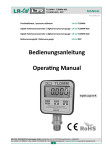
Digital Test Pressure Gauge LDM 70
- The battery powered digital pressure gauge LDM 70
has been exclusively designed for applications in
hydraulics and pneumatics as well as for mechanical
engineering. It can be easily and quickly installed in
situ.
- It is in the responsibility of the user to verify whether the
chosen device is suitable for the intended application.
In case of any doubts, contact our sales department to
eliminate any indistinctness. DRUCK & TEMPERATUR
Leitenberger GmbH does not assume any liability for an
incorrect selection and its consequences!
- Permissible media are gases or liquids, specified in the
data sheet. Additionally the operator has to ensure that
the medium is compatible with the media wetted parts,
for the intended application.
- The technical data listed in the current data sheet are
engaging and must be complied with. If the data sheet
is not available, please order or download it from the
DOWNLOAD
area
on
our
homepage.
(http://www.druck-temperatur.de)
WARNING! – Danger through improper usage!
1.6 Package contents
Please verify that all listed parts are undamaged included in
the delivery and check for consistency specified in your
order:
- digital pressure gauge LDM 70
- this operating manual
2. Product identification
DRUCK & TEMPERATUR Leitenberger GmbH
Bahnhofstr. 33
D – 72138 Kirchentellinsfurt
GERMANY
E-Mail: [email protected]
Internet: www.druck-temperatur.de
Tel.: +49-7121-90920-0
Fax: +49-7121-90920-99
1. General information
1.1 Information on the operating manual
This operating manual contains important information on
proper usage of the device. Read this operating manual
carefully before installing and starting up the pressure
measuring device.
Adhere to the safety notes and operating instructions which
are given in the operating manual. Additionally applicable
regulations regarding occupational safety, accident
prevention as well as national installation standards and
engineering rules must be complied with!
This operating manual is part of the device and must be
kept at a, for the personnel always accessible location,
close to the installation position of the device.
This operating manual is copyrighted. The contents of this
operating manual reflect the version available at the time of
printing. It has been issued to our best knowledge and
belief. However, errors may have occurred. For incorrect
statements and their consequences, liability cannot be
assumed by DRUCK & TEMPERATUR Leitenberger GmbH.
–
Technical modifications reserved –
The device can be identified by its manufacturing label. It
provides the most important data. By the ordering code, the
product can be clearly identified. For identification of the
firmware the program version will appear for about 1 second
in the display after starting up the device. Please hold it
ready for inquiry calls.
Bestellschlüssel
Seriennu
mmer
Nenndruck
CE-Kennzeichnung
Fig. 1 manufacturing label (Nenndruck = nominal pressure;
Bestellschlüsse = order code; Seriennummer = serial
number; CE-Kennzeichnung = CE mark)
! Place the protective cap on the pressure port again
immediately after disassembling.
! Handle the unprotected diaphragm very carefully - it is
very sensitive and may be easily damaged.
! Do not use any force when installing the device to
prevent damage of the device and the plant!
! The display and the plastic housing are equipped with
rotational limiters. Please do only rotate the display or
the housing within the limit.
Take care that no mechanical stresses occur at the
pressure port as a result of the installation, since this
may cause a shifting of the characteristic curve.
In hydraulic systems, position the device in such a way
that the pressure port points upward (venting).
Provide a cooling line when using the device in steam
lines.
3.2 General installation steps
- Carefully remove the pressure measuring device from
the package and dispose of the package properly.
- Then go ahead as detailed in the specific instructions
below.
3.3 Installation steps for EN 837
- Use a suitable seal, corresponding to the medium and
the pressure input (e. g. a cooper gasket).
- Ensure that the sealing surface of the taking part is
perfectly smooth and clean.
- Screw the device into the corresponding thread by
hand.
- Tighten it with a SW 27 wrench
(for G1/4": approx. 20 Nm; for G1/2": approx. 50 Nm).
3.4 Installation steps for NPT connections
- Use a suitable seal, corresponding to the medium and
the pressure input (e. g. a PTFE-strip).
- Screw the device into the corresponding thread by
hand.
- Tighten it with a SW 27 wrench (for 1/4" NPT: approx.
30 Nm; for 1/2" NPT: approx. 70 Nm).
3.5 Positioning of the display module
The display module of the pressure gauge is rotatable so
that clear readability is guaranteed even on unusual
installation positions.
! The manufacturing label must not be removed from the
device!
3. Installation
3.1 Mounting and safety instructions
WARNING! Install the device only when depressurized
and currentless!
WARNING! This device may only be installed by
qualified technical personnel who has read and
understood the operating manual!
! Handle this electronic precision measuring device
carefully in packed as well as in unpacked condition!
! The device must not be subject to any changes or
modifications.
! The device may not be thrown!
! To avoid damaging the diaphragm, remove packaging
and protective cap only directly before starting up the
device. A delivered protective cap must be stored!
Fig. 2 display module
4. Initial start-up
WARNING! Before start-up, the user has to check for
proper installation and for any visible defects.
WARNING! The device can be started and operated by
authorized personnel only, who have read and understood the operating manual!
WARNING! The device has to be used within the
technical specifications, only (compare the data in the
data sheet)!
5. Operation
5.1 Operating and display elements
limit exeeding
neg. / pos.
1.2 Symbols used
DANGER! – Dangerous situation, which may result in
serious or fatal injuries
WARNING! – Potentially dangerous situation, which
may result in fatal or serious injuries
CAUTION! – Potentially dangerous situation, which
may result in minor injuries
! CAUTION! – Potentially dangerous situation, which
may result in damage of objects
NOTE – Tips and information for the user to ensure
good conditions for the operation.
1.3 Target group
WARNING! To avoid hazards for the operator and
damages of the device, following described instructions
have to be worked out by qualified technical personnel.
1.4 Limitation of liability
No liability is assumed and warranty claims are excluded in
case of non-observance of the operating manual, improper
application, modification of or damage to the device.
symbol for
indicate low
batteries
measured value
unit
Fig. 3 LC-display
The indication of the measured value as well as the
configuration of the individual parameters occurs menudriven via the LC display. The individual functions can be
set with the help of three miniature push buttons located in
the front.
The menu system is a closed system allowing you to scroll
both forward and backward through the individual set-up
menus to navigate to the desired setting item. All settings
are permanently stored in an EEPROM and therefore
available again even after a battery change.