1
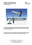
Bedienungs- und Installationsanleitung Installation- and Operation Instruction Strömungsmesser / Flow meter SM-6 / SM-6-V / S-SM Lesen Sie die Bedienungsanleitung vor dem Gebrauch des Gerätes gründlich durch, insbesondere die Hinweise unter Gliederungspunkt 2. Andernfalls könnten Gesundheits- oder Sachschäden auftreten. Die Bühler Technologies GmbH haftet nicht bei eigenmächtigen Änderungen des Gerätes oder für unsachgemäßen Gebrauch. Read this instruction carefully prior to installation and/or use. Pay attention particularly to all advises and safety instructions to prevent injuries. Bühler Technologies GmbH can not be held responsible for misusing the product or unreliable function due to unauthorised modifications. BX400001, 02/2011 Art. Nr. 90 31 053 Bühler Technologies GmbH, Harkortstr. 29, D-40880 Ratingen, Tel. +49 (0) 21 02 / 49 89-0, Fax. +49 (0) 21 02 / 49 89-20 Internet: www.buehler-technologies.com Email: [email protected] 1 Bedienungs- und Installationsanleitung Installation- and Operation Instruction Strömungsmesser / Flow meter SM-6 / SM-6-V / S-SM Inhaltsverzeichnis Seite 1 Einleitung ........................................................................................................................... 4 2 Hinweise ............................................................................................................................. 4 2.1 Gefahrenhinweise..............................................................................................................................5 3 Transport und Lagerungsvorschriften ............................................................................. 7 4 Aufbauen und Anschließen............................................................................................... 7 4.1 5 5.1 5.2 6 6.1 6.2 6.2.1 6.2.2 6.3 7 7.1 Montage des Grenzwertschalters mit Halterung (nur bei Typ SM-6 / SM-6-V) .................................7 Betrieb ................................................................................................................................ 8 Ablesen des Strömungsmessers.......................................................................................................8 Einstellen des Nadelventils ................................................................................................................8 Wartung .............................................................................................................................. 8 Wechsel des Grenzwertschalters mit Halterung (nur bei Typ SM-6 / SM-6-V) .................................9 Wechsel des Messglases - Strömungsmesser SM-6 / SM-6V .......................................................11 Ohne montiertem Grenzwertschalter ..........................................................................................11 Mit montiertem Grenzwertschalter ..............................................................................................11 Wechsel des Messglases - Sicherheitsströmungsmesser S-SM ....................................................12 Instandsetzung, Entsorgung .......................................................................................... 12 Entsorgen ........................................................................................................................................12 8 Fehlerbeseitigung............................................................................................................ 12 9 Beigefügte Dokumente.................................................................................................... 12 2 BX400001, 02/2011 Art. Nr. 90 31 053 Bedienungs- und Installationsanleitung Installation- and Operation Instruction Strömungsmesser / Flow meter SM-6 / SM-6-V / S-SM Contents Page 1 Introduction ..................................................................................................................... 13 2 Important advice ............................................................................................................. 13 2.1 Indications of risk ............................................................................................................................. 14 3 Transport and storing regulations ................................................................................. 16 4 Installation and connection ............................................................................................ 16 4.1 5 5.1 5.2 6 6.1 6.2 6.2.1 6.2.2 6.3 7 7.1 Mounting a flow sensor with brackets (type SM-6 / SM-6-V only) ................................................... 16 Operation ......................................................................................................................... 17 Read the flow value ......................................................................................................................... 17 Adjusting the needle valve............................................................................................................... 17 Maintenance .................................................................................................................... 17 Replacing the flow sensor with brackets (type SM-6 / SM-6-V only) ............................................... 18 Replacing the metering tube - Flow meters SM-6 / SM-6V ............................................................. 20 Without flow sensor ..................................................................................................................... 20 With flow sensor .......................................................................................................................... 20 Replacing the metering tube - Safety flow meters S-SM................................................................. 21 Repair and Disposal........................................................................................................ 21 Disposal ........................................................................................................................................... 21 8 Trouble shooting ............................................................................................................. 21 9 Attached Documents ...................................................................................................... 21 BX400001, 02/2011 Art. Nr. 90 31 053 3 Bedienungs- und Installationsanleitung Installation- and Operation Instruction Strömungsmesser / Flow meter SM-6 / SM-6-V / S-SM 1 Einleitung Diese Bedienungs- und Installationsanleitung gilt für Strömungsmesser vom Typ SM-6 / SM-6-V / S-SM. Alle Typen können zur Anzeige der Durchflussmenge von Messgasen oder flüssigen Medien verwendet werden. Welchen Typ Sie vor sich haben, ersehen Sie aus dem Typenschild. Auf diesem finden Sie neben der Auftragsnummer auch die Artikelnummer und Typbezeichnung. Sofern für einen Strömungsmesser Typ Besonderheiten gelten, sind diese in der Bedienungsanleitung gesondert beschrieben. Bitte beachten Sie beim Anschluss die Kennwerte der Strömungsmesser und bei Ersatzteilbestellungen die richtigen Ausführungen. Die Strömungsmesser der Baureihe SM-6/SM-6-V können zusätzlich mit einem bistabilen Grenzwertschalter ausgerüstet werden. Beim SM-6-V kann mit dem Nadelventil die Durchflussmenge eingestellt werden. Bei den Sicherheitsströmungsmessern der Baureihe S-SM ist der eigentliche Messkonus durch einen zweiten dickwandigen Glaszylinder geschützt. Sollte der Messkonus bersten, so übernimmt der äußere Glaszylinder den Schutz, so dass kein Medium ausströmen kann. Dieser äußere Glaszylinder ist zudem durch ein Edelstahlrohr gegen mechanische Beschädigungen geschützt. Die verschiedenen Typen des S-SM ersehen Sie aus dem Datenblatt. HINWEIS Die Strömungsmesser Typ SM-6, SM6-V und S-SM 3-1 erfüllen die grundlegenden Sicherheitsanforderungen der Richtlinie 94/9/EG und sind somit für den Einsatz im ExBereich geeignet (Zone 1, Gruppe IIC, Gefahrenhinweise in 2.1 dringend beachten). Durch die Strömungsmesser können nichtbrennbare Gase und brennbare Gase der Gruppe IIB (Typ SM-6 u. SM-6-V) oder IIC (Typ S-SM 3-1) geleitet werden, die im Normalbetrieb gelegentlich explosiv sein können (Zone 1). Das Typenschild der Strömungsmesser trägt jedoch keine Zündschutzkennzeichnung, da die Betriebsmittel nicht in den Anwendungsbereich der Richtlinie 94/9/EG fallen. 2 Hinweise Der Einsatz der Geräte ist nur zulässig, wenn: - das Produkt unter den in der Bedienungs- und Installationsanleitung beschriebenen Bedingungen, dem Einsatz gemäß Typenschild und für Anwendungen, für die es vorgesehen ist, verwendet wird. - die im Datenblatt und der Anleitung angegebenen Grenzwerte eingehalten werden. - Überwachungsvorrichtungen/ Schutzvorrichtung korrekt angeschlossen sind. - die Service- und Reparaturarbeiten, die nicht in dieser Anleitung beschrieben sind, von Bühler Technologies GmbH durchgeführt werden. - Originalersatzteile verwendet werden. Diese Bedienungsanleitung ist Teil des Betriebsmittels. Der Hersteller behält sich das Recht vor, die Leistungs-, die Spezifikations- oder die Auslegungsdaten ohne Vorankündigung zu ändern. Bewahren Sie die Anleitung für den späteren Gebrauch auf. 4 BX400001, 02/2011 Art. Nr. 90 31 053 Bedienungs- und Installationsanleitung Installation- and Operation Instruction Strömungsmesser / Flow meter SM-6 / SM-6-V / S-SM 2.1 Gefahrenhinweise Begriffsbestimmungen für Warnhinweise: HINWEIS Signalwort für wichtige Information zum Produkt auf die im besonderen Maße aufmerksam gemacht werden soll. VORSICHT Signalwort zur Kennzeichnung einer Gefährdung mit geringem Risiko, die zu einem Sachschaden oder leichten bis mittelschweren Körperverletzungen führen kann, wenn sie nicht vermieden wird. WARNUNG Signalwort zur Kennzeichnung einer Gefährdung mit mittlerem Risiko, die möglicherweise Tod oder schwere Körperverletzungen zur Folge hat, wenn sie nicht vermieden wird. GEFAHR Signalwort zur Kennzeichnung einer Gefährdung mit hohem Risiko, die unmittelbar Tod oder schwere Körperverletzung zur Folge hat, wenn sie nicht vermieden wird. In dieser Anleitung werden folgende Warnzeichen und Signalwörter benutzt: Warnung vor einer allgemeinen Gefahr Warnung vor explosionsgefährdeten Bereichen Netzstecker ziehen Warnung vor elektrischer Spannung Warnung vor heißer Oberfläche Atemschutz tragen Warnung vor dem Einatmen giftiger Gase Gesichtsschutz tragen Warnung vor ätzenden Flüssigkeiten Handschuhe tragen Das Gerät darf nur von Fachpersonal installiert werden, das mit den Sicherheitsanforderungen und den Risiken vertraut ist. Beachten Sie unbedingt die für den Einbauort relevanten Sicherheitsvorschriften und allgemein gültigen Regeln der Technik. Beugen Sie Störungen vor und vermeiden Sie dadurch Personen- und Sachschäden. Der für die Anlage Verantwortliche muss sicherstellen, dass: - Sicherheitshinweise und Betriebsanleitungen verfügbar sind und eingehalten werden, - Unfallverhütungsvorschriften der Berufsgenossenschaften beachtet werden; in Deutschland: Allgemeine Vorschriften” (VBG 1) und “Elektrische Anlagen und Betriebsmittel (VBG 4)”, - die zulässigen Daten und Einsatzbedingungen eingehalten werden, - Schutzeinrichtungen verwendet werden und vorgeschriebene Wartungsarbeiten durchgeführt werden, - bei der Entsorgung die gesetzlichen Regelungen beachtet werden. Wartung, Reparatur: - Reparaturen an den Betriebsmitteln dürfen nur von Bühler autorisiertem Personal ausgeführt werden. - Nur Umbau-, Wartungs- oder Montagearbeiten ausführen, die in dieser Bedienungs- und Installationsanleitung beschrieben sind. - Nur Original-Ersatzteile verwenden. Bei Durchführung von Wartungsarbeiten jeglicher Art müssen die relevanten Sicherheits- und Betriebsbestimmungen beachtet werden. BX400001, 02/2011 Art. Nr. 90 31 053 5 Bedienungs- und Installationsanleitung Installation- and Operation Instruction Strömungsmesser / Flow meter SM-6 / SM-6-V / S-SM ! GEFAHR Giftige, ätzende Gase Messgas kann gesundheitsgefährdend sein. Sorgen Sie ggf. für eine sichere Ableitung des Gases. Stellen Sie vor Beginn der Wartungsarbeiten die Gaszufuhr ab und sichern Sie sie gegen unbeabsichtigtes Aufdrehen. Spülen Sie den Strömungsmesser vor dem Öffnen mit Luft. Schützen Sie sich bei der Wartung vor giftigen / ätzenden Gasen. Tragen Sie die entsprechende Schutzausrüstung. HINWEIS Die Strömungsmesser Typ SM-6, SM6-V und S-SM 3-1 erfüllen die grundlegenden Sicherheitsanforderungen der Richtlinie 94/9/EG und sind somit für den Einsatz im Ex-Bereich geeignet (Zone 1, Gruppe IIC). Durch die Strömungsmesser können nichtbrennbare Gase und brennbare Gase der Gruppe IIB (Typ SM-6 u. SM-6-V) oder IIC (Typ S-SM 3-1) geleitet werden, die im Normalbetrieb gelegentlich explosiv sein können (Zone 1). ! GEFAHR Einsatz in explosionsgefährdeten Bereichen Brennbare Gase und Staub können sich entzünden oder explodieren. Vermeiden Sie die folgenden Gefahrenquellen: Elektrostatische Aufladung (Funkenbildung)! Reinigen Sie Gehäuseteile aus Kunststoff und Aufkleber nur mit einem feuchten Tuch. Metallische Gehäuseteile müssen geerdet werden. Zündtemperatur Beachten Sie die Zündtemperaturen explosiver Gase sowie maximal zulässige Oberflächentemperaturen T surf gemäß zutreffender Normen. Die maximale Oberflächentemperatur Tsurf des Betriebsmittels richtet sich nach der Mediumtemperatur Tmed. Es gilt Tsurf Tmed.. Bruchgefahr / Austritt explosiver oder giftiger Gase möglich. Schützen Sie das Betriebsmittel vor externen Schlageinwirkungen bzw. montieren Sie es schlaggeschützt. Gasaustritt Lebens- und Explosionsgefahr durch Gasaustritt bei nicht bestimmungsgemäßem Betrieb und bei Wartungsarbeiten möglich. 6 BX400001, 02/2011 Art. Nr. 90 31 053 Bedienungs- und Installationsanleitung Installation- and Operation Instruction Strömungsmesser / Flow meter SM-6 / SM-6-V / S-SM 3 Transport und Lagerungsvorschriften Die Produkte nur in der Originalverpackung oder einem geeigneten Ersatz transportieren. Bei längerer Nichtbenutzung sind die Betriebsmittel gegen Feuchtigkeit und Wärme zu schützen. Sie müssen in einem überdachten, trockenen und staubfreien Raum bei einer Temperatur von -10°C bis +40°C aufbewahrt werden. 4 Aufbauen und Anschließen Die Anschlussgewinde für die Gas Ein/Ausgänge der Strömungsmesser sind: Strömungsmesser Gewinde Strömungsmesser Gewinde SM-6 / SM-6-V G ¼“ S-SM 4 /S-SM 4-1 G ½“ S-SM 3-1 NPT ¼“ S-SM 5 G 1“ Das Montagebild entnehmen Sie bitte den angehängten Datenblättern. Die Fittings müssen mit Teflonband oder Dichtmittel bzw. Dichtring dicht eingeschraubt werden! 4.1 Montage des Grenzwertschalters mit Halterung (nur bei Typ SM-6 / SM-6-V) GEFAHR Einsatz in explosionsgefährdeten Bereichen Explosionsgefahr Verwenden Sie nur Grenzwertschalter mit der entsprechenden Zulassung. Der Grenzwertschalter wird vormontiert geliefert. Vor dem ersten Gebrauch lösen Sie die Kunststoffsenkschrauben an der Befestigungsplatte und positionieren Sie den Grenzwertschalter in die gewünschte Höhe. Die Kunststoffsenkschrauben müssen wieder befestigt werden. Verbinden Sie das Kabel mit der Stromversorgung. BX400001, 02/2011 Art. Nr. 90 31 053 7 Bedienungs- und Installationsanleitung Installation- and Operation Instruction Strömungsmesser / Flow meter SM-6 / SM-6-V / S-SM 5 Betrieb 5.1 Ablesen des Strömungsmessers Der Durchflusswert wird an der Oberkante des Schwebekörpers abgelesen. Beachten Sie bitte, dass die Werte nur stimmen können, wenn der Druck im Messrohr dem aufgedruckten Wert entspricht. 5.2 Einstellen des Nadelventils Bitte beachten Sie: das Nadelventil ist KEIN Absperrventil. Versuchen Sie bitte nicht, das Ventil mit großer Kraft weiterzudrehen! Das Ventil schließt bei Drehung im Uhrzeigersinn. 6 Wartung Die Geräte arbeiten weitgehend wartungsfrei. Die Wartung beschränkt sich zumeist auf die allgemeine Überprüfung und Funktionskontrolle der elektrischen Anlage. Im Fehlerfall beachten Sie bitte die Tabelle unter Kapitel 8. ! GEFAHR Gasaustritt Explosions- und Lebensgefahr Wenn explosive, giftige oder ätzende Gase durch die Strömungsmesser geleitet werden, sollte die Dichtheit der Strömungsmesser regelmäßig überprüft werden. ! GEFAHR Giftige, ätzende, explosionsfähige Gase Messgas kann gesundheitsgefährdend sein. Schalten Sie vor Beginn der Wartungsarbeiten den Prozess ab (druckfrei schalten). Schließen Sie dazu das Absperrventil (falls vorhanden). Spülen Sie den Strömungsmesser vor dem Öffnen mit Luft. Schützen Sie sich bei der Wartung vor giftigen / ätzenden Gasen. Tragen Sie die entsprechende Schutzausrüstung. ! ! GEFAHR Gasaustritt Explosions- und Lebensgefahr Verwenden Sie beschädigte Teile oder Dichtungen nicht wieder. Verwenden Sie nur Original-Ersatzteile. 8 BX400001, 02/2011 Art. Nr. 90 31 053 Bedienungs- und Installationsanleitung Installation- and Operation Instruction Strömungsmesser / Flow meter SM-6 / SM-6-V / S-SM 6.1 Wechsel des Grenzwertschalters mit Halterung (nur bei Typ SM-6 / SM-6-V) GEFAHR Einsatz in explosionsgefährdeten Bereichen Explosionsgefahr Verwenden Sie nur Grenzwertschalter mit der entsprechenden Zulassung. Entfernen Sie die Kunststoffsenkschrauben (1) an der Befestigungsplatte des Grenzwertschalters (siehe Abb. I). Gleichzeitig löst sich die Klemmplatte auf der Rückseite des Durchflussmessers. Lösen Sie beide Überwurfmuttern des Messrohres. Schieben Sie unter leichtem Druck das Messrohr in das obere Kopfstück hinein. Das Messrohr kann jetzt herausgeschwenkt werden (siehe Abb. II). Entfernen Sie auf der unteren Seite des Messrohres den Dichtring (2), die Überwurfmutter (3) und den Grenzwertschalter (4). Bei Bedarf kann das Messrohr gereinigt werden. Abb. I Abb. II Abb. III 1 2 3 4 1 Kunststoffsenkschrauben 3 Überwurfmutter 2 Dichtring 4 Grenzwertschalter mit Befestigungsplatte BX400001, 02/2011 Art. Nr. 90 31 053 9 Bedienungs- und Installationsanleitung Installation- and Operation Instruction Strömungsmesser / Flow meter SM-6 / SM-6-V / S-SM Lösen Sie beide Kreuzschlitzschrauben (8) an der Befestigungsplatte des Grenzwertschalters (siehe Abb. IV). Nehmen Sie die Befestigungsplatte (7) ab. Achten Sie darauf, dass die beiden Vierkantmuttern (6) in den Schlitzen des Grenzwertschalters nicht verloren gehen! Tauschen Sie den Grenzwertschalter (5) aus und schrauben Sie die Befestigungsplatte fest. Die gefräste Fase der Befestigungsplatte (7) muss nach links oben zeigen. Abb. IV Abb. V 7 5 8 6 5 Grenzwertschalter 7 Gefräste Befestigungsplatte 6 Vierkantmuttern M3 8 Kreuzschlitzschrauben Der Grenzwertschalter kann nun zurück auf das Messrohr geschoben werden. Achten Sie dabei auf die Durchflussrichtung, d.h. die Skalierung muss lesbar sein, die Befestigungsplatte des Grenzwertschalters muss mit den Schraubenlöchern über dem Langloch sitzen und das Kabel wird nach unten herausgeführt. Schieben Sie im Anschluss die Überwurfmutter und den Dichtring (mit dem Dichtkonus zur Halterung) auf das Messrohr. Setzen Sie das Messrohr wieder ein und ziehen Sie die Überwurfmutter mit der Hand fest. Mit beiden Kunststoffsenkschrauben kann nun die Befestigungsplatte durch den Längsschlitz in der Grundplatte des Durchflussmessers mit der in der Rückseite der Grundplatte eingelegten Klemmplatte verschraubt und justiert werden. 10 BX400001, 02/2011 Art. Nr. 90 31 053 Bedienungs- und Installationsanleitung Installation- and Operation Instruction Strömungsmesser / Flow meter SM-6 / SM-6-V / S-SM 6.2 Wechsel des Messglases - Strömungsmesser SM-6 / SM-6V 6.2.1 Ohne montiertem Grenzwertschalter Lösen Sie die beiden Überwurfmuttern des Messrohres. Schieben Sie unter leichtem Druck das Messglas in das obere Kopfstück hinein. Jetzt können Sie die unter den Überwurfmuttern liegenden Dichtringe auf den verjüngten Teil des Messglases verschieben. Das Messrohr kann jetzt herausgeschwenkt werden. Die Überwurfmuttern und Dichtringe können jetzt vom Messrohr entfernt und bei Bedarf auf das neue Messrohr geschoben werden. Die Montage des Messglases erfolgt in umgekehrter Reihenfolge. 6.2.2 Mit montiertem Grenzwertschalter Lösen Sie die obere Kunststoffsenkschraube (1) von der Befestigungsplatte des Grenzwertschalters (siehe Abb. I) und lockern Sie die untere Kunststoffsenkschraube (1), so dass sich der Grenzwertschalter frei verschieben lassen kann. Ein vollständiges Abnehmen von der Befestigungsplatte ist dabei nicht erforderlich. Lösen Sie beide Überwurfmuttern (3) des Messrohres. Schieben Sie unter leichtem Druck das Messglas in das obere Kopfstück hinein. Drehen Sie den Grenzwertschalter zur Seite (siehe Abb. Abb. VI), wenn Sie das Messglas aus dem Grenzwertschalter wie auch der Überwurfmutter heraus ziehen. Verschieben Sie den Grenzwertschalter dabei, falls es erforderlich ist. Entfernen Sie auf der unteren Seite des Messglases den Dichtring (2) und die Überwurfmutter (3). Der Grenzwertschalter verbleibt auf der Befestigungsplatte (siehe Abb. Abb. VII). Die Montage des Messrohres erfolgt in umgekehrter Reihenfolge. Abb. VI Abb. VII BX400001, 02/2011 Art. Nr. 90 31 053 11 Bedienungs- und Installationsanleitung Installation- and Operation Instruction Strömungsmesser / Flow meter SM-6 / SM-6-V / S-SM 6.3 Wechsel des Messglases - Sicherheitsströmungsmesser SSM Dieser Austausch muss sehr vorsichtig durchgeführt werden! Führen Sie ihn nur durch, wenn Sie sicher sind, ihn zu beherrschen. Wir empfehlen, den S-SM zum Hersteller zu schicken. Schrauben Sie ein Endstück aus dem VA-Schutzrohr. Halten Sie den Strömungsmesser dabei so, das beim Entfernen des Endstücks das Schutzglas und das Messrohr nicht von allein herausrutschen können. Das Messrohr kann jetzt herausgezogen werden. Bei der Montage des neuen Messrohres muss auf den richtigen Sitz des Messrohres und des Schutzrohres in den O-Ringaufnahmen der Endstücke geachtet werden. 7 Instandsetzung, Entsorgung Sollte ein Fehler beim Betrieb auftreten, finden Sie unter Gliederungspunkt 8. Hinweise für die Fehlersuche und Beseitigung. Sollten Sie Fragen haben, wenden Sie sich bitte an unseren Service Tel.: +49-(0)2102-498955 oder Ihre zuständige Vertretung. Ist nach Beseitigung eventueller Störungen und nach Einschalten der Netzspannung die korrekte Funktion nicht gegeben, muss das Gerät durch den Hersteller überprüft werden. Bitte senden Sie das Gerät zu diesem Zweck in geeigneter Verpackung an: Bühler Technologies GmbH - Reparatur/Service Harkortstraße 29 40880 Ratingen Deutschland Bringen Sie zusätzlich die Dekontaminierungserklärung ausgefüllt und unterschrieben an der Verpackung an. Ansonsten ist eine Bearbeitung Ihres Reparaturauftrages nicht möglich! Das Formular kann per E-Mail angefordert werden: [email protected]. 7.1 Entsorgen Bei der Entsorgung sind die gesetzlichen Vorschriften zu beachten. 8 Fehlerbeseitigung Problem / Störung Schwebekörper steigt nicht mögliche Ursache Abhilfe Nadelventil zugedreht Nadelventil öffnen Verschmutzung durch Staub reinigen 9 Beigefügte Dokumente - Datenblätter DD 400001, DD 400002, DD 400003 - Erklärung in Anlehnung an die Richtlinie 94/9/EG - Dekontaminierungserklärung 12 BX400001, 02/2011 HX400001 Art. Nr. 90 31 053 Bedienungs- und Installationsanleitung Installation- and Operation Instruction Strömungsmesser / Flow meter SM-6 / SM-6-V / S-SM 1 Introduction This manual is suitable for flow meter SM-6 / SM-6-V / S-SM. All types can be used to display flow rates of gases and liquids. You can get the probe type from the type plate. There is the order number and also a part number and type marking. If there are special instructions for a certain type, they are described in the manual. Regard the specific limits of the flow meters. Please only order the spare parts matching the probe type. Flow meters type SM-6/SM-6-V can be equipped with a bi-stable flow sensor. With SM-6-V the flow maybe adjusted by a needle valve. The safety flow meters S-SM consist of the metering glass inside a sealed protection glass. Thus if the metering glass would break, no gas or liquid would pour out. The protection glass itself sits inside a stainless steel shell giving outside protection. The different types can be seen from the data sheet. NOTE The flow meter SM-6 / SM-6-V / S-SM 3-1 correspond to the essential requirements of the directive 94/9/EC. Therefore they can be used in explosive atmosphere (Zone1, Group IIC, note indications of risk in 2.1). Inflammable gas and flammable gas which is only temporary explosive in normal operation (Zone 1; Group IIB (Type SM-6, SM-6-V) or IIC (Type S-SM 3-1)), can be led through the flow meter. There is no Ex-designation on the type plate of the flow meter, because they are not within the scope of directive 94 /9/EC. 2 Important advice Operation of the device is only valid if - the product is used under the conditions described in the installation- and operation instruction, the intended application according to the type plate and the intended use, - the performance limits given in the datasheets and in the installation- and operation instruction are obeyed, - monitoring devices and safety devices are installed properly, - service and repair is carried out by Bühler Technologies GmbH, unless described in this manual, - only original spare parts are used. This manual is part of the equipment. The manufacturer keeps the right to modify specifications without advanced notice. Keep this manual for later use. BX400001, 02/2011 Art. Nr. 90 31 053 13 Bedienungs- und Installationsanleitung Installation- and Operation Instruction Strömungsmesser / Flow meter SM-6 / SM-6-V / S-SM 2.1 Indications of risk Definitions for warnings: NOTE Signal word for important information to the product. CAUTION Signal word for a hazardous situation with low risk, resulting in damage to the device or the property or minor or medium injuries if not avoided. WARNING Signal word for a hazardous situation with medium risk, possibly resulting in severe injuries or death if not avoided. DANGER Signal word for an imminent danger with high risk, resulting in severe injuries or death if not avoided. The following warning signs and signal words are used in this manual: Warning against hazardous situation Warning against possible explosive atmospheres disconnect from mains Warning against electrical voltage Warning against hot surface wear respirator Warning against respiration of toxic gases wear face protection Warning against acid and corrosive substances wear gloves Installation of the device shall be performed by trained staff only, familiar with the safety requirements and risks. Check all relevant safety regulations and technical indications for the specific installation place. Prevent failures and protect persons against injuries and the device against damage. The person responsible for the system must secure that: - safety and operation instructions are accessible and followed, local safety regulations and standards are obeyed, performance data and installation specifications are regarded, safety devices are installed and recommended maintenance is performed, national regulations for disposal of electrical equipment are obeyed. Maintenance and repair - Repairs on the device must be carried out by Bühler authorized persons only. - Only perform modifications, maintenance or mounting described in this manual. - Only use original spare parts. During maintenance regard all safety regulations and internal operation instructions. 14 BX400001, 02/2011 Art. Nr. 90 31 053 Bedienungs- und Installationsanleitung Installation- and Operation Instruction Strömungsmesser / Flow meter SM-6 / SM-6-V / S-SM DANGER Toxic and corrosive gases Sample gas can be hazardous. Take care that the gas is exhausted in a place where no persons are in danger. Before maintenance turn off the gas supply and make sure that it cannot be turned on unintentionally. Protect yourself during maintenance against toxic / corrosive gases. Use gloves, respirator and face protector under certain circumstances. NOTE The flow meter SM-6 / SM-6-V / S-SM 3-1 correspond to the essential requirements of the directive 94/9/EC. Therefore they can be used in explosive atmosphere (zone1, Group IIC). Inflammable gas and flammable gas which is only temporary explosive in normal operation (zone 1; group IIB (Type SM-6, SM-6-V) or IIC (Type S-SM 3-1)), can be led through the flow meter. ! DANGER Application in explosive atmosphere Combustible gases and dust may inflame or explode. Avoid the following hazardous situations: Electrostatic charge Clean plastic parts and labels with damp cloth only. Connect metallic housings to ground. Ignition temperature Regard the ignition temperature of the explosive gas-atmosphere as well as maximum allowable surface temperatures (regard directive 94/9/ EC and harmonized standards). The maximum surface temperature Tsurf of the equipment corresponds to the medium-temperature Tmed ; (Tsurf Tmed). Risk of breakage / emission of explosive or toxic gas possible. Protect the equipment against being hit. Gas leakage Life and explosion risk may result from gas leakage due to improper use or during maintenance. Before maintenance release the process pressure and rinse the flow meter with air before opening. BX400001, 02/2011 Art. Nr. 90 31 053 15 Bedienungs- und Installationsanleitung Installation- and Operation Instruction Strömungsmesser / Flow meter SM-6 / SM-6-V / S-SM 3 Transport and storing regulations The equipment should only be transported in the original case or in appropriate packing. Protect the equipment against heat and humidity. The flow meter must be stored in roofed, dry, and dust free room. Temperature should be between -10°C and 40°C (14°F and 104°F). 4 Installation and connection The flow meters are equipped with the following threads: flow meter thread flow meter thread SM-6 / SM-6-V G ¼“ S-SM 4 /S-SM 4-1 G ½“ S-SM 3-1 NPT ¼“ S-SM 5 G 1“ The drawings for mounting are attached in the data sheet. The fittings have to be inserted with Teflon band, paste or sealing ring. 4.1 Mounting a flow sensor with brackets (type SM-6 / SM-6-V only) DANGER Application in explosive atmosphere Explosion risk Only use certificated flow sensors. The flow meter is delivered with pre-installed flow sensor. Prior to first use, loosen the plastic screws at the mounting plate and position the flow sensor at the required height. Fasten the plastic screws. Connect the cable to the mains supply. 16 BX400001, 02/2011 Art. Nr. 90 31 053 Bedienungs- und Installationsanleitung Installation- and Operation Instruction Strömungsmesser / Flow meter SM-6 / SM-6-V / S-SM 5 Operation 5.1 Read the flow value The flow value can be read at the top of the float. Please note: The values can only be correct, if the medium and pressure specified on the type plate match the sample. 5.2 Adjusting the needle valve Please note: The needle valve is NOT a shut-off valve. Do not force the valve. The valve is closed turning clockwise. 6 Maintenance There is largely no need of maintenance. If moisture or particles have clogged the metering tube, it can be dismounted and cleaned according to 6.1, see also chapter 8 (trouble shooting). ! DANGER Gas leakage Explosion risk and live danger If explosive, toxic or corrosive gas (liquid) will lead through the flow meter, check the leak tightness at regular intervals. ! DANGER Toxic, corrosive, explosive gases Sample gas can be hazardous. Before replacement of the tube release the process pressure and rinse filter with air (clear water) before opening. Protect yourself against toxic / corrosive gas or liquid during maintenance. Use gloves, gas mask and face protector under certain circumstances. ! DANGER Gas leakage ! Explosion risk and live danger Don’t reuse worn or defect components and gaskets. Only use original spare parts. BX400001, 02/2011 Art. Nr. 90 31 053 17 Bedienungs- und Installationsanleitung Installation- and Operation Instruction Strömungsmesser / Flow meter SM-6 / SM-6-V / S-SM 6.1 Replacing the flow sensor with brackets (type SM-6 / SM-6-V only) DANGER Application in explosive atmosphere Explosion risk Only use certificated flow sensors. Remove the plastic screws (1) at the mounting plate of the flow sensor (see Fig. I). At the same time, the clamping plate at the rear side of the flow meter becomes loose. Loosen both nuts at the end of the metering tube. Press the tube slightly to the top into the headpiece. The metering tube can now be tilted (see Fig II). Remove the gasket (2) from the bottom of the metering tube, the nut (3) and the flow sensor (4). If necessary, clean the metering tube. Fig. I Fig. II Fig. III 1 2 3 4 1 Plastic screw 3 Nut 2 Gasket 4 Flow sensor with bracket 18 BX400001, 02/2011 Art. Nr. 90 31 053 Bedienungs- und Installationsanleitung Installation- and Operation Instruction Strömungsmesser / Flow meter SM-6 / SM-6-V / S-SM Loosen both cross-head screws (8) at the mounting bracket of the flow sensor (see Fig. IV). Remove the plate (7). Be careful not to lose the square nuts (6) which fit into the grooves of the flow sensor! Replace the flow sensor (5) and remount the mounting plate. Make sure that the bevel at the plate points to the upper left corner. Fig. IV Fig. V 7 5 8 6 5 Flow sensor 7 Bevel 6 Square nut 8 Cross-head screws The flow sensor can now be pushed back to the metering tube. Regard the flow direction, the scaling has to be readable. Place the flow sensor with the mounting plate in front of the slot hole. The cable points downwards. Now push the nut and the gasket (with its cone pointing towards the bracket) onto the metering tube. Remount the metering tube and fix the nuts hand tight. Screw the mounting plate with the two plastic screws to the clamping plate which is placed into the split hole from the rear side of the flow meter. Adjust the flow sensor at the correct position and fix the plastic screws. BX400001, 02/2011 Art. Nr. 90 31 053 19 Bedienungs- und Installationsanleitung Installation- and Operation Instruction Strömungsmesser / Flow meter SM-6 / SM-6-V / S-SM 6.2 Replacing the metering tube - Flow meters SM-6 / SM-6V 6.2.1 Without flow sensor Remove both nuts at the end of the metering tube. Press the tube slightly to the top into the headpiece. Now slide the gaskets below the nuts to the tapered part of the metering tube. The metering tube can now be tilted and removed. Remove the nuts and gaskets from the old measuring tube and place them on the new one. Mount the metering tube in reverse order. 6.2.2 With flow sensor Remove the upper plastic screw (1) at the mounting plate of the flow sensor (see Fig. I) and loosen the lower plastic screw (1). The limit switch can now be moved. You don’t need to remove the flow sensor completely. Remove both nuts (3) at the end of the metering tube. Press the tube slightly to the top into the headpiece. Turn the flow sensor to the side (see Fig. VI) to remove the metering tube from the brackets and the nuts. Move the flow sensor if necessary. Remove the lower gasket (2) and nut (3) from the metering tube. The flow sensor stays at the mounting plate (see Fig. VII). Mount the new metering tube in reverse order. Fig. VI 20 Fig. VII BX400001, 02/2011 Art. Nr. 90 31 053 Bedienungs- und Installationsanleitung Installation- and Operation Instruction Strömungsmesser / Flow meter SM-6 / SM-6-V / S-SM 6.3 Replacing the metering tube - Safety flow meters S-SM This procedure has to be carried out very carefully. You should only do it yourself, if you are sure, you are able to cope with it. We recommend sending the flow meter back to the manufacturer. Screw one of the end pieces out of the flow meter while holding the flow meter in a direction preventing the metering tube from slipping out. The metering tube can now be taken out. When mounting the new metering tube the metering and the protection glass has to fit correctly into the Orings and end pieces! 7 Repair and Disposal If the device shows irregularities see chapter 8 for troubleshooting If you need help or more information call +49(0)2102-498955 or your local agent. If the device doesn’t work correctly after elimination of failures and turning power on, the device must be checked by the manufacturer. Please ship the device with suitable packing to Bühler Technologies GmbH - Service Harkortstrasse 29 40880 Ratingen Germany In Addition, attach the filled in and signed Declaration of Decontamination status to the packing. Otherwise, your repair order cannot be processed! The form can be requested by e-mail to [email protected]. 7.1 Disposal Regard the local regulations for disposal. 8 Trouble shooting Problem / Failure float doesn’t rise Possible cause Solution needle valve closed open needle valve pollution by liquid or particles clean metering tube 9 Attached Documents - Datasheets; DE/DA 400001, DE/DA 400002, DE/DA 400003 - Declaration according to Directive 94/9/EC: HX400001 - Declaration of Contamination status BX400001, 02/2011 Art. Nr. 90 31 053 21 ® Strömungsmesser SM - 6 / SM - 6 - V Die hochkorrosionsfesten Strömungsmesser der Baureihe SM eignen sich für die Durchflussmessung in gasförmigen und flüssigen Medien. Beim SM-6-V kann mit dem integrierten Nadelventil die Durchflussmenge eingestellt werden. In Gasaufbereitungssystemen kann der Strömungsmesser auch zur Überwachung des gesamten Systems eingesetzt werden. Dazu wird er mit einem bistabilen Grenzwertschalter ausgerüstet. Nach Einregulierung der gewünschten Durchflussmenge wird der Grenzwertschalter auf dem Messrohr justiert. Sollte jetzt, während des Betriebes der Durchfluss absinken, z. B. weil der Filter verstopft ist, wird ein Signal ausgelöst. Zur Ansteuerung des Grenzwertschalters stehen mehrere Trennschaltverstärker zur Auswahl. (siehe Datenblatt DD 40 0003). DD 40 0001 02/2011 § Korrosionsfeste Materialien § Einfacher Aufbau § Messrohr einfach zu wechseln § Grenzwertschalter optional Bühler Technologies GmbH D - 40880 Ratingen, Harkortstr. 29 Tel.: + 49 (0) 2102 / 49 89-0 Fax: + 49 (0) 2102 / 49 89-20 Internet: www.buehler-technologies.com e-mail: [email protected] Abmessungen (mm) G1/4 G1/4 27 SM - 6 - V 50 50 27 SM - 6 250 250 200 100 150 100 50 50 ø5,5 42 ø5,5 42 G1/4 28 51 A000242 150 105 216 A000242 105 205 200 28G1/4 max.79 Einsatz in explosionsgefährdeten Bereichen: Das Typenschild der Strömungsmesser trägt keine Zündschutzkennzeichnung, da die Betriebsmittel nicht in den Anwendungsbereich der Richtlinie 94/9/EG fallen. Sie erfüllen jedoch die grundlegenden Sicherheitsanforderungen der Richtlinie 94/9/EG und sind somit für den Einsatz im gasexplosionsgefährdeten Bereich (Zone 1, Gruppe IIC ) geeignet. Hinweise in der Bedienungsanleitung beachten! Technische Daten Strömungsmesser Technische Daten Grenzwertschalter Umgebungstemperatur Mediumtemperatur Schutzart Umgebungstemperatur Gehäusematerial Überwurfmutter Grundplatte Klemmschraube Schaltpunkt 20 Messrohr Schwebekörper 34 PTFE PTFE PVDF / Viton oder PCTFE / Perfluorelastomer Borosilikatglas Hastelloy C 4 oder optional PEEK mit Weicheiseneinlage PPS glasfaserverstärkt PA IP 67 DIN 40050 -20 °C bis +70 °C PBT A000241X Material Köpfe Dichtung Verstellspindel 7 Betriebsdruck max. + 80 °C £ 150°C, bei Sondermessbereichen max. 80 °C 4 bar Bestellhinweise Grenzwertschalter Artikel Nr. 40 56 0 0 0 1 0 2 0 3 0 4 0 5 0 6 0 7 0 8 0 9 1 0 Messbereich* 99 0 1 2 S - Luft 6 - 60 NL/h Luft 10 - 100 NL/h Luft 25 - 250 NL/h Luft 50 - 500 NL/h Luft 80 - 800 NL/h Wasser 0,5 - 5 L/h Wasser 1,2 - 12 L/h Wasser 2,5 - 25 L/h Wasser 4 - 40 L/h Wasser 6 - 60 L/h Sondermessbereich ohne Nadelventil Ventil PVDF / Viton Ventil PCTFE / Perfluorelastomer Grenzwertschalter mit Halterung ohne Grenzwertschalter * Standard Messrohre; Luft 20 °C 1,2 bar abs; Wasser 20 °C Klemmschraube Bestellhinweis zum Grenzwertschalter: Ein Grenzwertschalter wird werkseitig montiert, wenn an die letzte Stelle der Artikelnummer ein “S” gesetzt wird. Ohne die Markierung “S” bleibt der Strömungsmesser ohne Grenzwertschalter. Technische Änderungen vorbehalten ® Flow Meter SM - 6 / SM - 6 - V These highly corrosion resistant flow meters are suitable for both liquid and gaseous applications. The SM-6-V combines a flow meter with a precision needle valve to regulate and adjust the flow. In applications where flow monitoring is critical, the flow meter can be equipped with a bi-stable flow sensor. Any deviation from the set point results in an alarm signal. § Highly corrosion resistant § Reliable construction § Easy maintenance metering tube § Optional flow sensor available The flow sensor can be connected to a range of controllers (see data sheet DE 40 0003) DE 40 0001 02/2011 Bühler Technologies GmbH D - 40880 Ratingen, Harkortstr. 29 Tel.: + 49 (0) 2102 / 49 89-0 Fax: + 49 (0) 2102 / 49 89-20 Internet: www.buehler-technologies.com e-mail: [email protected] Dimensions (mm) G1/4 G1/4 27 SM - 6 - V 50 50 27 SM - 6 250 250 200 100 150 100 50 50 ø5,5 42 ø5,5 42 G1/4 28 51 A000242 150 105 216 A000242 105 205 200 28G1/4 max.79 Application in explosive atmosphere: There is no Ex-designation on the type plate of the equipment, because they are not within the scope of Eurepean Directive 94/9/EC. However the equipment corresponds to the essential requirements of the Directive 94/9/EC. Therefore they can be used in explosive atmosphere (Zone 1 , Group IIC). Observe all cautions in the Installation and Operation Manual. Technical Data: Flow Meter Technical Data: Flow Sensor Ambient temperature 80 °C Media temperature max. 150°C (with part no. 405610 max. 80°C) Operating pressure max. 4 bar Protection class Ambient temperature Housing material 20 Union nut Base plate Locking screw 7 Metering tube Float A000241X PTFE PTFE PVDF / Viton or PCTFE / Perfluorelastomer Borosilicate glass Hastelloy C 4 or optional PEEK with iron core PPS fiberglass reinforced PA 34 Material Head Seal Adjusting screw IP 67 DIN 40050 -20 °C - +70 °C PBT Switch point Please indicate with order: Flow sensor Part no. 40 56 0 0 0 0 0 0 0 0 0 0 1 Range* 99 0 1 2 3 4 5 6 7 8 9 0 0 1 2 S - air 6 - 60 NL/h air 10 - 100 NL/h air 25 - 250 NL/h air 50 - 500 NL/h air 80 - 800 NL/h water 0,5 - 5 L/h water 1,2 - 12 L/h water 2,5 - 25 L/h water 4 - 40 L/h water 6 - 60 L/h special range without needle valve valve PVDF / Viton valve PCTFE / perfluorelastomer flow sensor with mounting brackets without flow sensor * standard measuring tube; air 20 °C 1,2 bar abs; water 20 °C Locking screw Ordering information for flow meter: The flow meter is delivered with pre-installed flow sensor if the last character of the part number is marked with "S". Otherwise the flow meter has no flow sensor installed. we reserve the right to amend specification Flow Meter SM - 6 / SM - 6 - V These highly corrosion resistant flow meters are suitable for both liquid and gaseous applications. The SM-6-V combines a flow meter with a precision needle valve to regulate and adjust the flow. In applications where flow monitoring is critical, the flow meter can be equipped with a bi-stable flow sensor. Any deviation from the set point results in an alarm signal. § Highly corrosion resistant § Reliable construction § Easy maintenance metering tube § Optional flow sensor available The flow sensor can be connected to a range of controllers (see data sheet DA 40 0003) DA 40 0001 02/2011 Buhler Technologies LLC 1030 West Hamlin Road, Rochester Hills, MI 48309 Phone: 248.652.1546 Fax: 248.652.1598 Internet: www.buhlertech.com e-mail: [email protected] Dimensions 1.97” 1.97” SM - 6 G1/4 1.06” G1/4 1.06” SM - 6 - V 250 250 100 150 100 50 50 ø 0.22” 1.65” 1.65” G1/4 1.10” 2.01” A000242 8.50” A000242 4.13” 8.07” 150 4.13” 200 200 ø 0.22” G1/4 28 max.79 Application in explosive atmosphere: There is no Ex-designation on the type plate of the equipment, because they are not within the scope of European Directive 94/9/EC. However the equipment corresponds to the essential requirements of the Directive 94/9/EC. Therefore they can be used in explosive atmosphere (Zone 1 , Group IIC). Observe all cautions in the Installation and Operation Manual! Technical Data: Flow Meter Technical Data: Flow Sensor Ambient temperature Media temperature max. (for part no. 405610 175°C) Operating pressure max. Protection class Ambient temperature Housing material Switch point 0.79” Locking screw 1.34” Union nut Base plate A000241X PTFE PTFE PVDF / Viton or PCTFE / Perfluorelastomer Borosilicate glass Hastelloy C 4 or Optional PEEK with iron core PPS fiberglass reinforced PA Metering tube Float IP 67 DIN 40050 -4 °F - 158 °F PBT 58 psig 0.28” Material Head Seal Adjusting screw 175 °F 300 °F Please indicate with order: Part no. 40 56 0 0 0 0 0 0 0 0 0 0 1 Range* Flow sensor 99 0 1 2 3 4 5 6 7 8 9 0 0 1 2 S - air 6 - 60 NL/h air 10 - 100 NL/h air 25 - 250 NL/h air 50 - 500 NL/h air 80 - 800 NL/h water 0,5 - 5 L/h water 1,2 - 12 L/h water 2,5 - 25 L/h water 4 - 40 L/h water 6 - 60 L/h special range without needle valve valve PVDF / Viton valve PCTFE / perfluorelastomer flow sensor with mounting brackets without flow sensor * standard measuring tube; air 68 °F 17.4 psig abs; water 68 °F Locking screw Ordering information for flow meter: The flow meter is delivered with pre-installed flow sensor if the last character of the part number is marked with "S". Otherwise the flow meter has no flow sensor installed. we reserve the right to amend specification ® Sicherheitsströmungsmesser S - SM Diese Strömungsmesser erfüllen die sehr hohen Anforderungen an die Betriebssicherheit, die besonders von der chemischen Industrie gestellt werden. Alle mit dem Medium in Berührung kommenden Teile bestehen aus Glas, Edelstahl rostfrei, PTFE oder Titan. Der Messkonus wird radial über PTFE armierte- oder Kalrez-ORinge abgedichtet. Werden PTFE-Endstücke verwendet, so werden diese aus Stabilitätsgründen in Edelstahl gefasst. Der Messkonus ist durch einen zweiten dickwandigen Glaszylinder geschützt, der ebenfalls in den Endstücken abgedichtet wird. Beide Gläser umschließt ein geschlitztes Edelstahlrohr. Sollte der Messkonus bersten, so übernimmt der äußere Glaszylinder den Schutz, so dass kein Medium ausströmen kann. Dieser ist wiederum durch das Edelstahlrohr gegen mechanische Beschädigung geschützt. § robuste, einfache Schutzsicherung § großer Anwendungsbereich § hoher Sicherheitsstandard DD 40 0002 10/2010 Bühler Technologies GmbH D - 40880 Ratingen, Harkortstr. 29 Tel.: + 49 (0) 2102 / 49 89-0 Fax: + 49 (0) 2102 / 49 89-20 Internet: www.buehler-technologies.com e-mail: [email protected] Technische Daten C siehe Tabelle Glas, Hastelloy, Edelstahl oder PTFE PTFE, Edelstahl oder Titan über mitgelieferte Rohrschellen aus Kunststoff A E ØF B H Meßbereich: Schwebekörper: Endstücke: Befestigung: A000061X SW G *Betriebsdruck max. [bar] = 10 Typ S-SM 3-1 S-SM 4 S-SM 4-1 S-SM 5 Betriebstemperatur max. [°C] - 20 10 ØD A B C ØD E ØF G H SW 197 368 368 370 17 17 17 25 17 23 23 23 25 50 50 70 42 68 68 95 5,5 6 6 6 1/4"NPT G 1/2" G 1/2" G 1" 27 40 40 58 22 36 36 46 kg Betriebsdruck* max. bei 20°C 0,9 10 bar 2,8 10 bar 2,8 10 bar 4 10 bar Betriebstemperatur* max. bei 2bar 100 °C 100 °C 100 °C 100 °C Tabellen typischer Messbereiche Strömungsmesser S-SM 3-1 Medium: Luft Druck: + 1,2 bar abs. Temperatur: + 20 °C 1,6 - 16 Nl/h 4 - 40 Nl/h 6 - 60 Nl/h 10 - 100 Nl/h 25 - 250 Nl/h 50 - 500 Nl/h 80 - 800 Nl/h Wasser + 20 °C 0,25 - 2,5 0,5 5 1,2 - 12 2,5 - 25 4 - 40 6 - 60 10 - 100 l/h l/h l/h l/h l/h l/h l/h Strömungsmesser S-SM 4 / S-SM 4-1 Medium: Luft Druck: + 1,2 bar abs. Temperatur: + 20 °C 250 - 2500 Nl/h 400 - 4000 Nl/h 500 - 5000 Nl/h 800 - 8000 Nl/h Strömungsmesser S-SM 5 Medium: Luft Druck: + 1,2 bar abs. Temperatur: + 20 °C 1000 - 10000 Nl/h 1600 - 16000 Nl/h 2000 - 20000 Nl/h 3000 - 30000 Nl/h Wasser + 20 °C 6,3 - 63 10 - 100 16 - 160 25 - 250 40 - 400 63 - 630 l/h l/h l/h l/h l/h l/h Wasser + 20 °C 25 - 250 40 - 400 63 - 630 100 - 1000 160 - 1600 250 - 2500 l/h l/h l/h l/h l/h l/h Einsatz in explosionsgefährdeten Bereichen: Das Typenschild der Strömungsmesser trägt keine Zündschutzkennzeichnung, da die Betriebsmittel nicht in den Anwendungsbereich der Richtlinie 94/9/EG fallen. Sie erfüllen jedoch die grundlegenden Sicherheitsanforderungen der Richtlinie 94/9/EG und sind somit für den Einsatz im gasexplosionsgefährdeten Bereich (Zone 1, Gruppe IIC ) geeignet. Hinweise in der Bedienungsanleitung beachten! Bestellhinweise Artikel Nr. 40 22 999 40 23 999 40 24 999 40 25 999 40 26 999 Beschreibung Strömungsmesser S-SM 3-1 Strömungsmesser S-SM 3-1 Strömungsmesser S-SM 4 Strömungsmesser S-SM 4-1 Strömungsmesser S-SM 5 Endstücke Edelstahl 1.4571 Endstücke Titan Endstücke Edelstahl 1.4571 / PTFE Endstücke Edelstahl 1.4571 Endstücke Edelstahl 1.4571 Technische Änderungen vorbehalten ® Safety Flow Meter S - SM Handling hazardous liquids or gases requires the use of flow meters with the vulnerable parts such as the metering glass protected against breakage. The S - SM safety flow meter provides sealed protection glass around the metering glass and an outer stainless steel shell with a sight window. A variety of construction materials is available to meet any specific application. § Rugged protection § Large range of applications § High safety standard DE 40 0002 10/2010 Bühler Technologies GmbH D - 40880 Ratingen, Harkortstr. 29 Tel.: + 49 (0) 2102 / 49 89-0 Fax: + 49 (0) 2102 / 49 89-20 Internet: www.buehler-technologies.com e-mail: [email protected] Technical Data C See table* Glass, Hastelloy, SS or PTFE PTFE, SS or titanium Bracket made of plastic A E ØF H Metering range: Metering cone: Endcaps: Support: operating temperature max. [°C] - 20 10 B *Operating pressure max. [bar] = 10 - A000061X SW G ØD Type S-SM 3-1 S-SM 4 S-SM 4-1 S-SM 5 A B C ØD E ØF G H SW 197 368 368 370 17 17 17 25 17 23 23 23 25 50 50 70 42 68 68 95 5,5 6 6 6 1/4"NPT G 1/2" G 1/2" G 1" 27 40 40 58 22 36 36 46 kg Operating pressure* Operating temperature* max. at 20°C max. at 2bar 0.9 10 bar 100 °C 2.8 10 bar 100 °C 2.8 10 bar 100 °C 4 10 bar 100 °C Table of Typical Ranges Flow meter S-SM 3-1 Media: Air Pressure: + 1.2 bar abs. Temperature: + 20 °C 1,6 16 Nl/h 4 40 Nl/h 6 60 Nl/h 10 - 100 Nl/h 25 - 250 Nl/h 50 - 500 Nl/h 80 - 800 Nl/h Water + 20 °C 0.25 - 2.5 0.5 5 1.2 - 12 2.5 - 25 4 - 40 6 - 60 10 - 100 l/h l/h l/h l/h l/h l/h l/h Flow meter S-SM 4 / S-SM 4-1 Media: Air Pressure: + 1.2 bar abs. Temperature: + 20 °C 250 - 2500 Nl/h 400 - 4000 Nl/h 500 - 5000 Nl/h 800 - 8000 Nl/h Flow meter S-SM 5 Media: Air Pressure: + 1.2 bar abs. Temperature: + 20 °C 1000 - 10000 Nl/h 1600 - 16000 Nl/h 2000 - 20000 Nl/h 3000 - 30000 Nl/h Water + 20 °C 6.3 - 63 10 - 100 16 - 160 25 - 250 40 - 400 63 - 630 l/h l/h l/h l/h l/h l/h Water + 20 °C 25 - 250 40 - 400 63 - 630 100 - 1000 160 - 1600 250 - 2500 l/h l/h l/h l/h l/h l/h Application in explosive atmosphere: There is no Ex-designation on the type plate of the equipment, because they are not within the scope of European Directive 94/9/EC. However the equipment corresponds to the essential requirements of the Directive 94/9/EC. Therefore they can be used in explosive atmosphere (Zone 1 , Group IIC). Regard the indications of the Installation- and Operation-Instruction. Please indicate with order Part no. 40 22 999 40 23 999 40 24 999 40 25 999 40 26 999 Description Flow meter S-SM 3-1 Flow meter S-SM 3-1 Flow meter S-SM 4 Flow meter S-SM 4-1 Flow meter S-SM 5 Endcaps: SS 1.4571 Endcaps: titanium Endcaps: SS 1.4571 / PTFE Endcaps: SS 1.4571 Endcaps: SS 1.4571 we reserve the right to amend specification Safety Flow Meter S - SM Handling hazardous liquids or gases requires the use of flow meters with the vulnerable parts such as the metering glass protected against breakage. The S - SM safety flow meter provides sealed protection glass around the metering glass and an outer stainless steel shell with a sight window. A variety of construction materials is available to meet any specific application. § Rugged protection § Large range of applications § High safety standard DA 40 0002 10/2010 Buhler Technologies LLC 1030 West Hamlin Road, Rochester Hills, MI 48309 Phone: 248.652.1546 Fax: 248.652.1598 Internet: www.buhlertech.com Email: [email protected] Technical Data C See table* Glass, Hastelloy, SS or PTFE PTFE, SS or titanium Bracket made of plastic A E ØF H Metering range: Metering cone: Endcaps: Support: operating temperature max. [°C] - 20 10 B *Operating pressure max. [bar] = 10 - A000061X SW G ØD Type A B C ØD E 0.67 0.91 0.91 0.91 0.98 1.97 1.97 2.76 1.65 2.68 2.68 3.74 ØF G H SW 1.06 1.57 1.57 2.28 0.87 1.42 1.42 1.81 (in inches) S-SM 3-1 7.76 0.67 S-SM 4 14.49 0.67 S-SM 4-1 14.49 0.67 S-SM 5 14.57 0.98 0.22 1/4"NPT 0.24 G 1/2" 0.24 G 1/2" 0.24 G 1" lb Operating pressure* Operating temperature* max. at 68°F max. at 29 psig 2.0 145 psig 212 °F 6.2 145 psig 212 °F 6.2 145 psig 212 °F 8.8 145 psig 212 °F Table of Typical Ranges Flow meter S-SM 3-1 Media: Air Pressure: + 17.4 psig abs. Temperature: 68 °F 1.6 16 Nl/h 4 40 Nl/h 6 60 Nl/h 10 - 100 Nl/h 25 - 250 Nl/h 50 - 500 Nl/h 80 - 800 Nl/h Water 68 °F 0.25 - 2.5 l/h 0.5 5 l/h 1.2 - 12 l/h 2.5 - 25 l/h 4 - 40 l/h 6 - 60 l/h 10 - 100 l/h Flow meter S-SM 4 / S-SM 4-1 Media: Air Pressure: + 17.4 psig abs. Temperature: 68 °F 250 - 2500 Nl/h 400 - 4000 Nl/h 500 - 5000 Nl/h 800 - 8000 Nl/h Flow meter S-SM 5 Media: Air Pressure: + 17.4 psig abs. Temperature: 68 °F 1000 - 10000 Nl/h 1600 - 16000 Nl/h 2000 - 20000 Nl/h 3000 - 30000 Nl/h Water 68 °F 6.3 10 16 25 40 63 - 63 100 160 250 400 630 l/h l/h l/h l/h l/h l/h 68 °F 25 - 250 40 - 400 63 - 630 100 - 1000 160 - 1600 250 - 2500 l/h l/h l/h l/h l/h l/h Water Application in explosive atmosphere: There is no Ex-designation on the type plate of the equipment, because they are not within the scope of European Directive 94/9/EC. However the equipment corresponds to the essential requirements of the directive 94/9/EC. Therefore they can be used in explosive atmosphere (Zone 1, Group IIC). Regard the indications of the Installation and Operation Manual. Please indicate with order Part no. 40 22 999 40 23 999 40 24 999 40 25 999 40 26 999 Description Flow meter S-SM 3-1 Flow meter S-SM 3-1 Flow meter S-SM 4 Flow meter S-SM 4-1 Flow meter S-SM 5 Endcaps: SS 1.4571 Endcaps: titanium Endcaps: SS 1.4571 / PTFE Endcaps: SS 1.4571 Endcaps: SS 1.4571 we reserve the right to amend specification ® Trennschaltverstärker für SM - 6 / SM - 6 - V Zur Ansteuerung des Grenzwertschalters für Strömungsmesser SM - 6 stehen verschiedene Trennschaltverstärker zur Auswahl. Einkanalige Trennschaltverstärker Typ KFD/KFA für eigensichere Steuerstromkreise mit einem Signalausgang (Wechsler), Leitungsbruchüberwachung, 3 LEDs zur Funktionsüberwachung von Spannung, Alarmausgang und Leitungsbruch. Die Geräte müssen außerhalb des explosionsgefährdeten Bereiches installiert werden! § Montage auf 35 mm Normschiene nach DIN EN 60715 § Eigensichere Eingänge § Zulassungen ATEX, FM, UL, CSA Einkanaliger Verstärker Typ KCD im kompakten Klemmengehäuse mit Schaltzustandsanzeige LED und Leitungsbruchüberwachung. DD 40 0003 03/2013 Bühler Technologies GmbH D - 40880 Ratingen, Harkortstr. 29 Tel.: + 49 (0) 2102 / 49 89-0 Fax: + 49 (0) 2102 / 49 89-20 Internet: www.buehler-technologies.com e-mail: [email protected] Technische Daten Grenzwertschalter Schutzart IP 67 DIN 40050 Umgebungstemperatur -20...+70 °C Betrieb bistabil Kabellänge 2m Zulassung PTB 99 ATEX 2128X Ex II 2 G Ex ia II C T6 Zeichnung siehe Datenblatt Strömungsmesser Technische Daten Trennschaltverstärker Versorgungsspannung KFD 2-SR2-Ex 1.W 20 - 30 V DC KFA 5-SR2-Ex 1.W 103,5 - 126 V AC 45 - 65 Hz KFA 6-SR2-Ex 1.W 207 - 253 V AC 45 - 65 Hz KCD2-E2L 24 24 V DC eigensicher nach Leitungsüberwachung EN 60079-11 ja EN 60079-11 ja EN 60079-11 ja nein ja Zulassungen PTB 00 ATEX 2080 ExII(1)GD [Ex ia]IIC PTB 00 ATEX 2081 ExII(1)GD [Ex ia]IIC PTB 00 ATEX 2081 ExII(1)GD [Ex ia]IIC UL Class I Groups A, B, C, D Class II Groups E, F, G UL Class I Groups A, B, C, D Class II Groups E, F, G UL Class I Groups A, B, C, D Class II Groups E, F, G CSA Class I, Div. 1 Groups A, B, C, D Class II, Div. 1 Groups E, F, G CSA Class I, Div. 1 Groups A, B, C, D Class II, Div. 1 Groups E, F, G CSA Class I, Div. 1I Groups A, B, C, D Class II, Div. 1I Groups E, F, G Weitere auf Anfrage Ausgang (nicht eigensicher) Wechsler Wechsler Wechsler Schließer PNP-Transistor Schaltstromausgang 230 V AC, 2 A cos j > 0,7 40 V DC, 2 A ohmsche Last 230 V AC, 2 A cos j > 0,7 40 V DC, 2 A ohmsche Last 230 V AC, 2 A cos j > 0,7 40 V DC, 2 A ohmsche Last 200 mA DC Umgebungstemperatur -20...+60 °C -20...+60 °C -20...+60 °C -25...+70 °C Schutzart IP 20 IP 20 IP 20 IP 20 Abmessungen BxHxT 20x118x115 mm BxHxT 20x118x115 mm BxHxT 20x118x115 mm BxHxT 20x63x44 mm Bestellhinweise Artikel Nr. 91 000 700 04 91 000 700 05 91 000 700 06 91 000 700 07 49 490 19 Beschreibung Trennschaltverstärker, KFD2-SR2-Ex 1.W, 24 V DC Trennschaltverstärker, KFA5-SR2-Ex 1.W, 115 V AC Trennschaltverstärker, KFA6-SR2-Ex 1.W, 230 V AC Trennschaltverstärker, KCD2-E2L, 24 V DC Grenzwertschalter mit Halterung Technische Änderungen vorbehalten ® Switch Amplifiers for SM - 6 / SM - 6 - V A variety of switch amplifiers is available for the SM-6 flow meter. For intrinsically safe circuits, use the model KFD/KFA single channel switch amplifier. This model features an alarm relay (change over contact), broken wire detection, and 3 status indicator LEDs for power, alarm and broken wire. § Rail mounting (DIN EN 60715) § Intrinsically safe inputs § ATEX, FM, UL, CSA approvals Also available is Model KCD – a single channel amplifier in a compact housing with LED status indication and broken wire detection. DE 40 0003 03/2013 Bühler Technologies GmbH D - 40880 Ratingen, Harkortstr. 29 Tel.: + 49 (0) 2102 / 49 89-0 Fax: + 49 (0) 2102 / 49 89-20 Internet: www.buehler-technologies.com e-mail: [email protected] Technical Data: Flow Sensor Protection class IP 67 DIN 40050 Approved by PTB 99 ATEX 2128X Ambient temperature -20...+70 °C Ex II 2 G Ex ia II C T6 Operating Bi-stable For drawing see data sheet flow meter SM-6 Cable length 2m Technical Data: Controllers Power supply KFD 2-SR2-Ex 1.W 20 - 30 V DC KFA 5-SR2-Ex 1.W 103.5 - 126 V AC 45 - 65 Hz KFA 6-SR2-Ex 1.W 207 - 253 V AC 45 - 65 Hz KCD2-E2L 24 24 V DC Intrinsically safe acc. to Broken wire detection EN 60079-11 Yes EN 60079-11 Yes EN 60079-11 Yes No Yes Approved by PTB 00 ATEX 2080 ExII(1)GD [Ex ia]IIC PTB 00 ATEX 2081 ExII(1)GD [Ex ia]IIC PTB 00 ATEX 2081 ExII(1)GD [Ex ia]IIC UL Class I Groups A, B, C, D Class II Groups E, F, G UL Class I Groups A, B, C, D Class II Groups E, F, G UL Class I Groups A, B, C, D Class II Groups E, F, G CSA Class I, Div. 1 Groups A, B, C, D Class II, Div. 1 Groups E, F, G CSA Class I, Div. 1 Groups A, B, C, D Class II, Div. 1 Groups E, F, G CSA Class I, Div. 1I Groups A, B, C, D Class II, Div. 1I Groups E, F, G Others on request Output (not intrisically safe) Change over Change over Change over Closing PNP-Transistor Switch power output 230 V AC, 2 A cos j > 0.7 40 V DC, 2 A Resistance load 230 V AC, 2 A cos j > 0.7 40 V DC, 2 A Resistance load 230 V AC, 2 A cos j > 0.7 40 V DC, 2 A Resistance load 200 mA DC Ambient temperature -20...+60 °C -20...+60 °C -20...+60 °C -25...+70 °C Protection class IP 20 IP 20 IP 20 IP 20 Dimensions WxHxD 20x118x115 mm WxHxD 20x118x115 mm WxHxD 20x118x115 mm WxHxD 20x63x44 mm Please indicate with order Part no. 91 000 700 04 91 000 700 05 91 000 700 06 91 000 700 07 49 490 19 Description Controller, KFD2-SR2-Ex 1.W, 24 V DC Controller, KFA5-SR2-Ex 1.W, 115 V AC Controller, KFA6-SR2-Ex 1.W, 230 V AC Controller, KCD2-E2L, 24 V DC Flow sensor we reserve the right to amend specification Controllers for SM - 6 / SM - 6 - V A variety of controllers is available for the SM-6 flow meter. For intrinsically safe circuits, us the Model KFD/KFA single channel controller. This model features an alarm relay (change over contact), broken wire detection, and 3 status indicator LEDs for power, alarm and broken wire. § Rail mounting (DIN EN 60715) § Intrinsically safe inputs § ATEX, FM, UL, CSA approvals Also available is Model KCD – a single channel amplifier in a compact housing with LED status indication and broken wire detection. DA 40 0003 03/2013 Buhler Technologies LLC 1030 West Hamlin Road, Rochester Hills, MI 48309 Phone: 248.652.1546 Fax: 248.652.1598 Internet: www.buhlertech.com Email: [email protected] Technical Data: Flow Sensor Protection class IP 67 DIN 40050 Approved by PTB 99 ATEX 2128X Ambient temperature -5 - 160 °F Ex II 2 G Ex ia II C T6 Operation Bi-stable For drawing see data sheet for Flow meter SM-6 Standard cable length 2 m (approx. 79”) Technical Data: Controllers Power supply KFD 2-SR2-Ex 1.W 20 - 30 V DC KFA 5-SR2-Ex 1.W 103.5 - 126 V AC 45 - 65 Hz KFA 6-SR2-Ex 1.W 207 - 253 V AC 45 - 65 Hz KCD2-E2L 24 24 V DC Intrinsically safe acc. To Broken wire detection EN 60079-11 Yes EN 60079-11 Yes EN 60079-11 Yes No Yes Approved by PTB 00 ATEX 2080 ExII(1)GD [Ex ia]IIC PTB 00 ATEX 2081 ExII(1)GD [Ex ia]IIC PTB 00 ATEX 2081 ExII(1)GD [Ex ia]IIC UL Class I Groups A, B, C, D Class II Groups E, F, G UL Class I Groups A, B, C, D Class II Groups E, F, G UL Class I Groups A, B, C, D Class II Groups E, F, G CSA Class I, Div. 1 Groups A, B, C, D Class II, Div. 1 Groups E, F, G CSA Class I, Div. 1 Groups A, B, C, D Class II, Div. 1 Groups E, F, G CSA Class I, Div. 1I Groups A, B, C, D Class II, Div. 1I Groups E, F, G Others on request Output (not intrisically safe) Change over Change over Change over Closing PNP-Transistor Switch power output 230 V AC, 2 A cos j > 0.7 40 V DC, 2 A Resistance load 230 V AC, 2 A cos j > 0.7 40 V DC, 2 A Resistance load 230 V AC, 2 A cos j > 0.7 40 V DC, 2 A Resistance load 200 mA DC Ambient temperature -5 - 140 °F -5 - 140 °F -5 - 140 °F -15 - 160 °F Protection class IP 20 IP 20 IP 20 IP 20 Dimensions WxHxD 20 x 118 x 115 mm 0.79 x 4.95 x 4.53” WxHxD 20 x 118 x 115 mm 0.79 x 4.95 x 4.53” WxHxD 20 x 118 x 115 mm 0.79 x 4.95 x 4.53” WxHxD 20 x 63 x 44 mm 0.79 x 2.48 x 1.73” Please indicate with order Part no. 91 000 700 04 91 000 700 05 91 000 700 06 91 000 700 07 49 490 19 Description Controller, KFD2-SR2-Ex 1.W, 24 V DC Controller, KFA5-SR2-Ex 1.W, 115 V AC Controller, KFA6-SR2-Ex 1.W, 230 V AC Controller, KCD2-E2L, 24 V DC Flow sensor we reserve the right to amend specification EG-Konformitätserklärung EC-declaration of conformity Hiermit erklären wir, dass die nachfolgenden Produkte den wesentlichen Anforderungen der folgenden EGRichtlinie in ihrer aktuellen Fassung entsprechen: Herewith we declare that the following products correspond to the essential requirements of the following EC directive in its actual version: 94/9/EWG (ATEX) Produkte / products: Strömungsmesser / Flow meter Typ(en) / type(s): SM-6 / SM-6-V / S-SM 3-1 Alle Typen können zur Anzeige der Durchflussmenge von Gasen oder flüssigen Medien verwendet werden. Durch die Strömungsmesser können nichtbrennbare Gase und brennbare Gase, die im Normalbetrieb gelegentlich explosiv sein können, geleitet werden (Zone 1, Gruppe IIC (Typ S-SM 3-1) oder Gruppe IIB (Typ SM-6, SM-6-V)). Die Strömungsmesser dürfen nur durch Fachpersonal installiert werden; die einschlägigen Sicherheitsvorschriften sind zwingend zu beachten. Beachten sie auch die Hinweise in der zugehörigen Bedienungsanleitung. Die Produkte sind für den Einsatz in explosionsgefährdeten Bereichen der Zone 1 (Gruppe IIC) geeignet. All flow meter types can be used to display flow rates of gases or liquids. Inflammable gases and flammable gases, only temporary explosive in normal operation, can led through the flow meters (zone 1, group IIC (Type S-SM 3-1) or group IIB (types SM-6, SM-6-V)). The flow meters have to be installed by trained personnel. All safety regulations have to be fulfilled. The flow meter can be used in zone 1 (group IIC). Note also the indications in the Installation- and Operation Instruction. Zur Beurteilung der Konformität wurden folgende harmonisierte Normen in aktueller Fassung herangezogen: The following harmonized standards in actual revision have been used: • EN 1127-1 • EN 13463-1 • EN13463-5 Explosionsfähige Atmosphären, Explosionsschutz, Teil1: Grundlagen und Methodik Nichtelektrische Geräte für den Einsatz in explosionsgefährdeten Bereichen, Teil 1 Nichtelektrische Geräte für den Einsatz in explosionsgefährdeten Bereichen, Teil 5 Dokumentationsverantwortlicher für diese Konformitätserklärung ist der Unterzeichnende mit Anschrift am Firmensitz. The person authorised to compile the technical file is the one that has signed and is located at the company’s address Ratingen, den 15.10.2010 __________________________________ Stefan Eschweiler Geschäftsführer – Managing Director HX 40 0001 Bühler Technologies GmbH, Harkortstr. 29, D-40880 Ratingen, Tel. +49 (0) 21 02 / 49 89-0, Fax. +49 (0) 21 02 / 49 89-20 Internet: www.buehler-technologies.com Dekontaminierungserklärung Declaration of Contamination status Gültig ab / valid since: 2011/05/01 Revision 0 ersetzt Rev. / replaces Rev --- Die gesetzlichen Vorschriften schreiben vor, dass Sie uns die Dekontaminierungserklärung ausgefüllt und unterschrieben zurück zu senden haben. Die Angaben dienen zum Schutz unserer Mitarbeiter. Bringen Sie die Bescheinigung an der Verpackung an. Ansonsten ist eine Bearbeitung Ihres Reparaturauftrages nicht möglich! Legal regulations prescribe that you have to fill in and sign the Declaration of Contamination status and send it back. This information is used to protect our employees. Please attach the declaration to the packing. Otherwise, your repair order cannot be processed. Gerät / Device: Serien-Nr. / Serial no. : Rücksendegrund / Reason for return: [ ] Ich bestätige hiermit, dass das oben spezifizierte Gerät ordnungsgemäß gereinigt und dekontaminiert wurde und keinerlei Gefahren im Umgang mit dem Produkt bestehen. I herewith declare that the device as specified above has been properly cleaned and decontaminated and that there are no risks present when dealing with the device. Ansonsten ist die mögliche Gefährdung genauer zu beschreiben / In other cases, please describe the hazards in detail: Aggregatzustand (bitte ankreuzen) / Condition of aggregation (please check): Flüssig / Liquid Fest / Solid Pulvrig / Powdery Gasförmig / Gaseous Folgende Warnhinweise sind zu beachten (bitte ankreuzen) / The following safety advices must be obeyed (please check): Explosiv Explosives Giftig / Tödlich Acute toxicity Entzündliche Stoffe Flammable Brandfördernd Oxidizing Komprimierte Gase Gas under pressure Gesundheitsgefährdend Irritant toxicity Gesundheitsschädlich Health hazard Umweltgefährdend Environmental hazard Bitte legen Sie ein aktuelles Datenblatt des Gefahrenstoffes bei / Please include the current material safety data sheet of the hazardous material! Angaben zum Absender / Information about the dispatcher: Firma / Company: Anschrift / Address: Ansprechpartner / Contact person: Abteilung / Division: E-Mail: Tel. / Phone: Fax: Ort, Datum / Location, date: Unterschrift / Stempel Signature / Stamp: Bühler Technologies GmbH D - 40880 Ratingen, Harkortstr. 29 Tel.: + 49 (0) 2102 / 4989-0 Fax: + 49 (0) 2102 / 4989-20 e-mail: [email protected] Internet: www.buehler-technologies.com