1
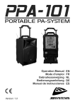
ENGLISH OPERATION MANUAL CONNECTIONS Use good quality cables to prevent bad audio quality. (JB Systems has a complete range of good quality audio cables) For more information on connections, please refer to the next chapter. Be sure to turn off the unit before you make changes to the different connections. In this manual we talk about “line inputs”. This is a global name for inputs with a level between 750mV and 2V. This includes tuners, videos, CD-players, etc. FUNCTIONS 1. ANTENNAS WIRELESS MICS: The PPA-01 has 2 wireless microphones, each with their own receiver antenna. The left antenna (1A) is for mic-A (8A), the right antenna is for mic-B (8B). Both antennas should be stored in the compartment on top of the unit (26) during transport. 2. RF-SIGNAL LED: is lit while the signal from the wireless mic is received. If this LED is off while the wireless mic is switched on, there could be 3 reasons: The wireless mic and receiver use a different channel: set both to the same channel! The batteries in the wireless mic are weak (RF-signal often blinks irregularly): change the batteries. The the wireless mic is out of range (RF-signal often blinks irregularly): bring the wireless mic closer to the receiver. 3. AF-SIGNAL LED: The indicator lights to indicate that an audio signal is received. 4. OUTPUT LEVEL METER: this meter indicates the output level, make sure to keep the meter out of the red region. 5. TUNER/DVD/USB-PLAYER: multifunctional player with many possibilities. See next chapter for more information. 6. TUNER ANTENNA: to be used when the tuner (5) is used for reception of FM-stations. Put the antenna in the position with the best reception. 7. MIC1/LINE1 ~ MIC2/LINE2 CHANNELS: balanced mono input channels (jack and XLR-3pin) for balanced/unbalanced mic or line signals. Important: make sure to close the level knob (12) before connecting a music signal. JB SYSTEMS® 3/58 PPA-01