1
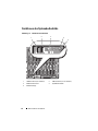
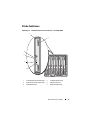
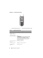
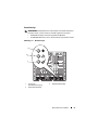
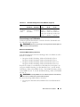
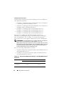
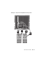
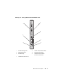
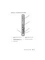
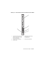
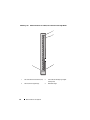
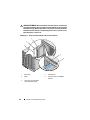
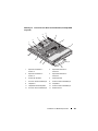
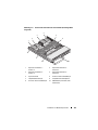
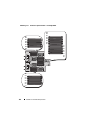
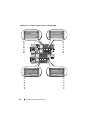
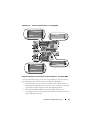
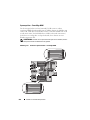
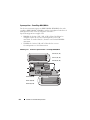
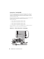
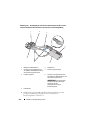
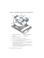
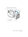
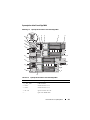
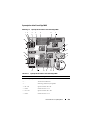
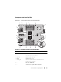
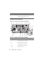
Systemplatine beim PowerEdge M610
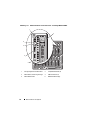
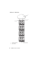
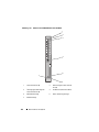
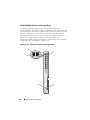
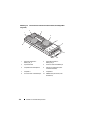
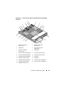
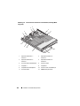
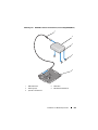
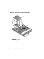
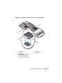
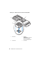
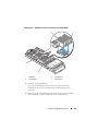
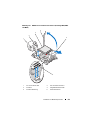
Abbildung 7-7. Systemplatinenanschlüsse beim PowerEdge M610
4
3
2
1
13
12
5
11
6
13
10
9
8
7
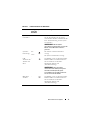
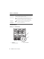
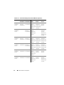
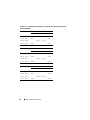
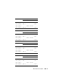
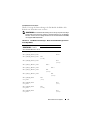
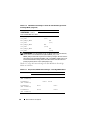
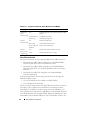
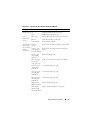
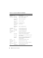
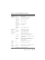
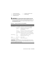
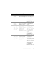
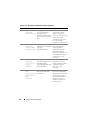
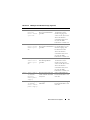
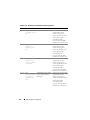
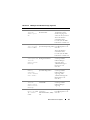
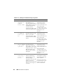
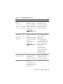
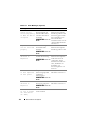
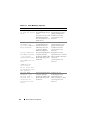
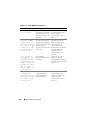
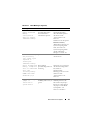
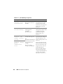
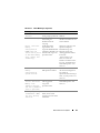
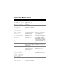
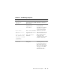
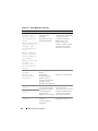
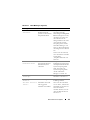
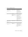
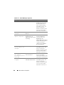
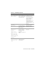
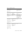
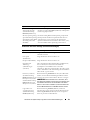
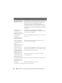
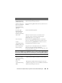
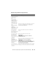
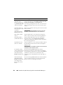
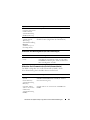
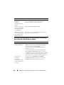
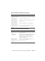
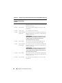
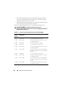
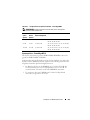
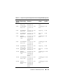
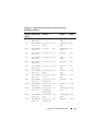
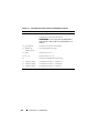
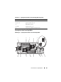
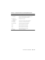
Tabelle 7-15. Systemplatinenanschlüsse beim PowerEdge M610
Anschluss
Beschreibung
1
MEZZ1_FAB_C
Zusatzkartenanschluss 1 – Struktur C
2
MEZZ1_FAB_B
Zusatzkartenanschluss 2 – Struktur B
3
A1 – A6
Speichermodule A1 – A6
4
-
Sockel für Hardwareschlüssel zum Aktivieren der
integrierten NIC-Funktion
5
CPU2
Sockel für Prozessor 2
6
PWRD_EN,
NVRAM_CLR
Systemkonfigurations-Jumper
7
-
Anschluss für Speichercontrollerkarte
8
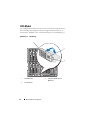
BATTERY
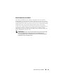
Anschluss für 3,0-V-Knopfzellenbatterie
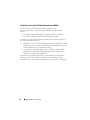
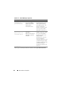
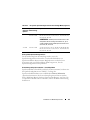
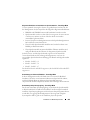
ANMERKUNG: Für den Zugang muss die Systemplatine
entfernt werden. Siehe „Entfernen der Systemplatine“ auf
Seite 291.
366
Informationen zur Systemplatine