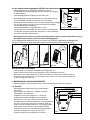
1
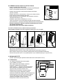
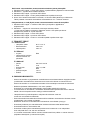
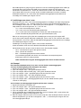
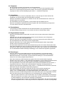
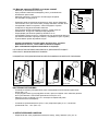
7. CONSTRUCTION OF THE STEAM ROOM:
- The steam room must be well insulated, especially the ceiling, through which most of the steam
escapes. Because of the humidity, it is recommended the insulation be covered with a moisture
resistant material, for instance aluminum foil. Wood must always be used to panel the walls.
8. PROTECTIVE BARRIER:
- A protective barrier may be built around the heater if necessary. In this case, you should
definitely adhere to the minimum clearances from structures made of flammable materials.
9. IMPORTANT ADDITIONAL INSTRUCTIONS:
-
-
-
-
-
-
-
You should be careful in the vicinity of the hot heater, because the stones and
metal parts of the heater may cause burns.
Only a small amount of water (1-2 dl) should be thrown onto the heater stones, because
the steaming water is scalding hot.
This equipment is not to be used by children or people whose physical and psychological traits, mental
functions, lack of experience or knowledge may hinder the safe operation of the equipment, if the
person who is responsible for safety cannot supervise them or instruct them in the use of the equipment.
Children may not be left unsupervised and they should be supervised to make sure
they do not play with the equipment.
Always inspect the steam room before plugging in the heater.
The improperly filed stone container is a fire hazard.
Covering the stove will cause a fire hazard.
When measuring the insulation barrier of the heater, some leakage may occur, which is
caused by the humidity that has seeped into the insulation material during transport
or warehousing. The moisture will evaporate after the heater is heated a few times.
Do not connect the power supply for the electric heater through a fault current protection!
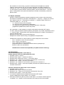
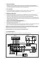
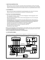
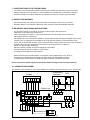
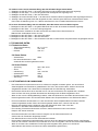
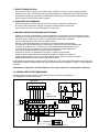
10. CONNECTION SCHEME:
The location of the connectors in the wiring diagram is indicative. See the markings on the circuit board.
Overheating
protection
Display
__
CLK
Y-AL.
J1-1
J1-2
J1-3
J1-4
J1-5
J1-6
A2
B1
Blue
White
A1
B2
Red
CTL
Yellow
NTC
-t
+12V
NTC
Control unit
J7
1
2
J8
ON/OFF
Switch
3
4
5
6
A1
J2
A2
B1
YLS.
J10
J9
B2
X6
NTC
VA1 VA2 VA3
N
N L1
L1 CTL CTL L2
L2 L3
L3
PE
PE
400V 3N~
Control of the electric heating