1
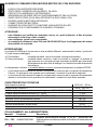
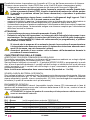
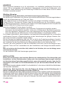
D749MA CHARACTERISTICS
BATTERY CHARGER BOARD (INTEGRATED)
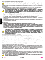
If the battery is connected the automation will operate in any case if there is no mains power
supply. If the voltage drops below 11.3 Vdc, the automation ceases to operate (the control unit
remains fed); whereas, when the voltage drops below 10.2 Vdc, the card completely disconnects
the battery (the control panel is no longer fed).
OBSTACLE DETECTION
If the obstacle detection function (which can be set through trimmer FR) is activated during an
opening manoeuvre, the automation closes approx. 20 cm., if it is activated during a closing
manoeuvre, the automation opens all the way .
WARNING: the control panel logics may interpret mechanical friction as an obstacle.
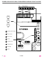
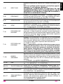
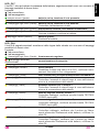
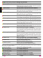
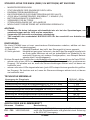
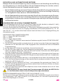
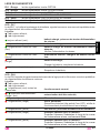
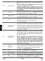
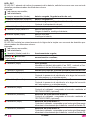
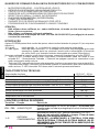
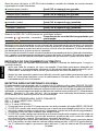
DIAGNOSTICS LED
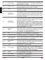
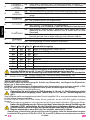
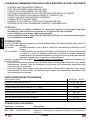
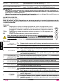
DL1 - Red
DL2 - Red
DL3 - Green
DL4 - Green
DL5 - Green
DL6 - Green
PEDESTRIAN button LED signal
OPEN/CLOSE button LED signal
STOP button LED signal
CLOSE button LED signal
PHOTOCELL LED signal
SENSITIVE EDGE LED signal
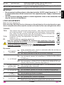
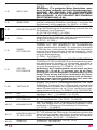
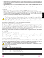
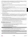
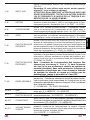
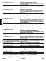
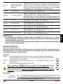
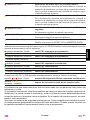
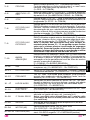
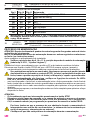
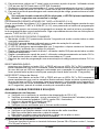
LED - DL7
Apart from highlighting the presence of the battery, LED DL7 displays any mistakes with a series
of pre-set fashes in various colours:
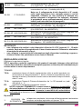
Key:
led always on;
led fashing;
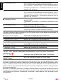
fully-charged battery, main voltage present;
always on (green):
battery charging;
always on (yellow):
1 fash every 4 seconds (green): fully-charged battery, no main voltage;
Check the main voltage;
1 fash every 4 seconds (yellow): external power, charger disabled;
low battery;
1 fash every 2 seconds (red):
Charge the battery, replace the battery;
faulty battery;
fast fashing (red):
Replace the battery;
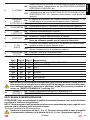
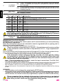
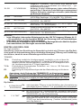
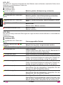
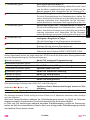
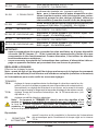
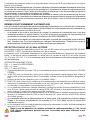
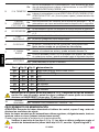
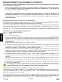
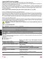
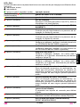
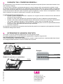
LED - DL8
The DL8 LED indicates mistakes in the board logic with a series of pre-set fashes in different
colours:
Key:
led always on;
led fashing;
1 fash every 4 seconds (green): normal operation;
D749MA
21
ENGLISH
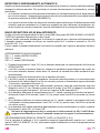
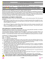
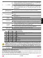
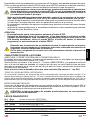
TIMER-OPERATED OPENING AND CLOSING CYCLES
The opening/closing of the automation can be controlled by means of a timer that has a free N.O.
output contact (relay). The timer must be connected to terminals 4 - 6 (OPEN/CLOSE button) and
can be programmed so that, at the desired opening time, the relay contact closes until the desired
closing time (when the timer’s relay contact opens, enabling the automatic closing of the gate).
Note: the automatic closing function must be enabled by setting Dip-switch no. 1 to ON).