1
A 5 amp fuse would be suffice for signal wires (non current wires).
Fuses are not supplied with the unit but can be purchased separate from your
local chandlery or from Sterling Power Products. Sterling Power Products has a
full range of high current fuses from 100-500 amps, the part number is GANLR for
the fuse holder and GANL100 for a 100 amp fuse and GANL200 for a 200 amp
fuse etc.
It is advisable, when doing any work on boats, to have someone close to you in
case of any problems. It is also a good idea to have a bottle of fresh water near by
incase of an unlikely explosion occurring in one of the batteries, the water can be
used to wash any acid out of your eyes.
To install the unit, pick a cool part of the engine room ( i.e. as low down as possible
) . It also does not matter which way up the unit goes. However, the unit has been
designed so the cables do not run across the bolts from other battery banks. If the
unit is connected, as per the obvious writing on the unit, the cables should be
brought up from below. You can connect the unit at any angle you wish to assist in
the wiring process. Using the 4 fixing holes you can firmly secure it to a bulkhead.
When all cables are connected, tie and secure the cables in such a way as their
weight is supported on the bulkhead and they do not vibrate nor touch any of the
other studs.
Ensure your alternator/s or other charging sources are working within the total
limits of the unit. I.e. if the unit is 80 amps the total maximum current is 80 amps, it
is important to keep the alternator rating lower than the relay’s ability for optimal
and safest operation.
Ensure all cable connections are correctly crimped with the correct tools, and the
rubber boots supplied are used to cover the exposed connection on completion.
Fit in a position to minimize the length of cables used, the shorter the cables the
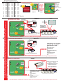
better. Look at the cable chart below for recommended cable sizes. Larger cables
are usually hard to come by; if, for example, you want a 200 amp cable, but only
have a 50 amp cable then simply run 4 lengths of 50 amp cable as, all you are
doing, is running copper.
The Pro Latch R can be configured into 4 different modes. Each of these
modes have a default setting.
1) Bidirectional charging: A conventional split charge relay suffers from high
power consumption to run itself. If used solely for charging a system with an
alternator the power used by the relay is insignificant and, as such, irrelevant
compared to the power generated. However, if after the engine is switched ‘off’
and there are solar cells or wind charging systems in the boat/vehicle then the
ability to charge other battery banks becomes very important. Therefore, the
power consumption of the splitting device becomes extremely important and so
the latching relay comes into a world of its own. There is no limit to how many
battery banks that can be charged. On boats there could be as many as 2-5
battery banks, simply use the appropriate number of latching relays to charge all
the battery banks either from a high power or low power charging source. An
instant starter disengage circuit is built in. This prevents the starter motor’s high
current surge damaging the product, this open circuits the relay between
activating the starter motor and the bendix engaging the fly wheel.
2) Battery Protection Mode: The battery protect system, protects a battery bank
from premature and expensive destruction due to deep discharge or over
charging. It only takes one accidental deep discharge of a battery bank to destroy
that battery bank, a very expensive mistake indeed. This is most common on
things such as hire boats or hire equipment, such as electric cherry pickers,
where the hirer tends not to treat the equipment with the respect it deserves. This
leaves the owner with a large battery replacement bill. The battery protection
relay disconnects the batteries at a preset limit in order to protect the battery
bank. The unit has a built in warning system, i.e. it will switch the power ‘off’ for 10
secs then back ‘on’ for 1 min to give a reasonable warning to allow the operator
time to complete the process, such as: start the engine or activate a battery
charger to take place to help the situation ( i.e. recharge the batteries ). This could
happen on a boat late at night, so, the extra minute allows some one to start the
engine to recover the batteries. For extra safety, the optional remote control gives
the option to override the trip for 1 min in the case of emergency.
3) Engine Start Protection Mode: This mode is designed to allow products to be
safely run from an engine starter battery and disconnects the product at such a
stage as to allow the engine starter battery to retain enough power to ensure the
engine will start. Ideal applications for this product are things such as tail lifts on
lorries, mobility vehicles, over night lorries (with D/C equipment) or small
inverters used on vans etc., where the addition of a split charge system and an
extra battery bank may not be warranted nor feasible ( obviously there are many
more applications for these products ). The product will then be automatically reengaged when the engine is started and/or the battery charged. Depending on
battery type this is the most likely mode where voltage adjustment maybe
required to fine tune the product to its application. It’s advisable to test this function
prior to releasing the job.
4) Unidirectional charging: much the same features as the Bidirectional setting,
however, the relay will only be activated by a voltage in excess of 13.3V ( x 2 for 24
v ) on the input cable stud only, the output cable voltage will not activate the
product. In the event that you need the output cable to do the activation simply
reverse the cables.
Examples of unidirectional charging
In a situation where you have a sealed lead acid (gel, AGM) starter battery and
an open lead acid domestic battery and you were fast charging your
domestic batteries at 14.8V using a shore powered battery charger / combined
inverter charger, you wouldn’t want to charge your AGM/Gel starter battery at
14.8V at the risk of damaging them.
The ProLatch R can therefore be implemented to isolate the starter and the
domestic when the domestic is being charged. In most situations the user will
be coming into shore and the relay will be engaged (allowing the domestic to
be charged from the engine starter). After arriving at shore and turning off the
engine the user must wait until the relay disengages (blue light turns off). Once
the relay is disengaged the user can then proceed to charge the domestic with
the shore powered battery charger and the relay shall remain disengaged.
IN THIS EXAMPLE unidirectional mode must be set at the starter battery side.
For example ‘ON’ voltage could be set at 13.3V - relay engaged domestic
being charged from starter. ‘OFF’ voltage could be set to 12.9V - when the
surface voltage of starter drops below 12.9V relay disengages. The relay will
then not engage again until the starter battery is being charged (surface
voltage raises above 13.3V).
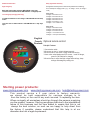
Optional remote control features: for these models there is an LCD display
showing input voltage, output voltage (selectable), high voltage trip alarm,
background light ‘on / off’ , sleep mode inductor and 1 min emergency override
ability and many other features.
How to select between the 4 modes
Factory default setting and brief installation guide: the unit is set as a charging
relay as new out of the box. If this is the function that you require then simply install
the unit.
The unit will power-up resulting in the illumination of all four indication LEDs and
then illuminate only the GREEN and YELLOW LED ( if voltage under 13.3 volts x 2
for 24 v ) or green and blue if over 13.3 volts ( relay engaged ) . The green should
be solid ( non flashing ) this confirms the unit is on ‘Bi directional charging mode’.
If you wish to change the mode to battery protect, start protect or uni directional
follow the procedure below:
How to adjust the main settings :
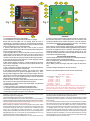
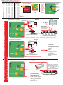
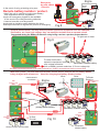
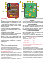
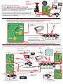
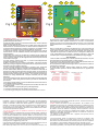
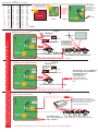
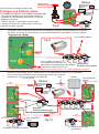
Refer to figs1+2 (page2) and figs3-10 (page5+6). Assuming unit is correctly wired.
For safety reasons remove the wires from the batteries rather than the unit; this
prevents loose, live wires floating around the product area.
1. Remove the negative wire from battery terminal.
2. Remove the lid by unscrewing the 2 screws securing the lid.
3. Using a small 1 or 2 inch (2.5-5cm) cable, link from CFG (7) to NEG (6) this will
result in two wires being in the NEG terminal (The link wire and the original
negative).
4. Remove the positive wire from your battery or target which connects to the ‘out’
terminal of the relay. Make sure there is absolutely no voltage on the output
terminal.
5.Now reconnect the negative wire back to your battery or distribution block (as
point 1). The unit should start up in configuration mode.
6.The unit will display all four information LED lights for 3 seconds ( blue , green.
yellow and red ) to test the LEDs are ok.
7.The unit will auto select 12V or 24V operation based on the input voltage ( its
there for important to ensure the battery bank is not totally flat. , the row of 6
LEDs behind the Sterling logo will illuminate, there are 4 green and 2 yellow.
Note: GREEN = 12V installation, yellow = 24V installation. The correct LED
indicators will then remain illuminated e.g. green =12V / yellow = 24V.
8.Once the blue and yellow LED lights switch off the unit is in programming
mode ( green and red leds on ) .