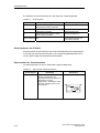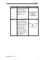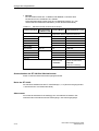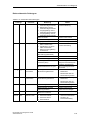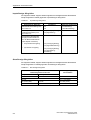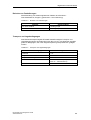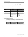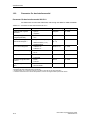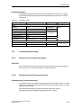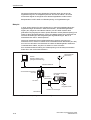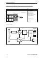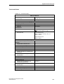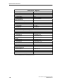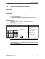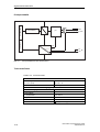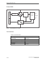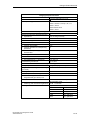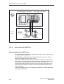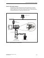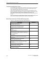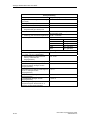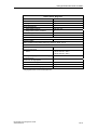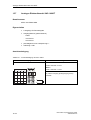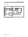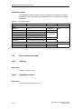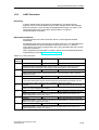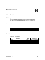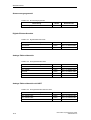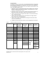
1
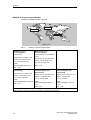
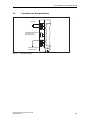
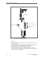
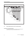
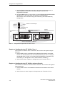
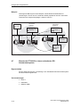
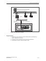
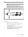
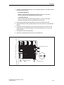
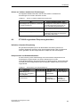
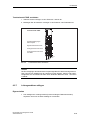
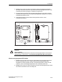
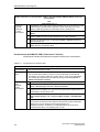
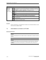
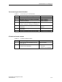
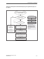
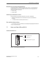
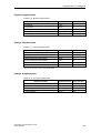
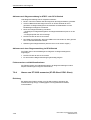
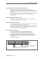
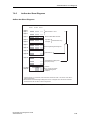
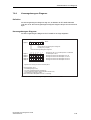
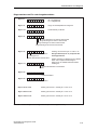
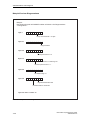
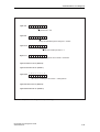
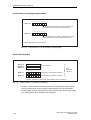
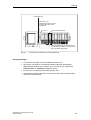
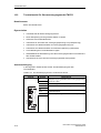
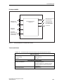
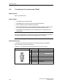
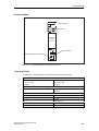
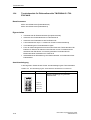
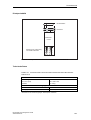
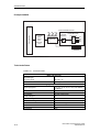
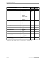
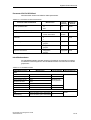
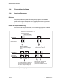
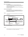
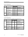
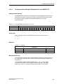
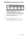
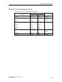
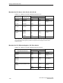
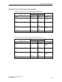
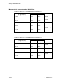
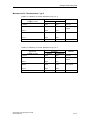
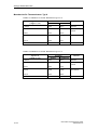
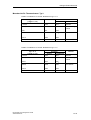
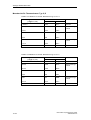
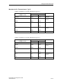
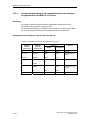
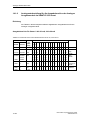
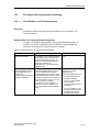
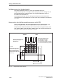
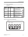
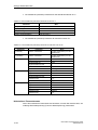
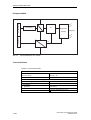
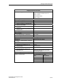
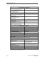
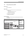
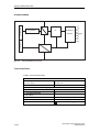
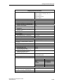
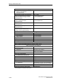
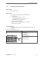
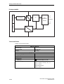
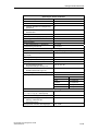
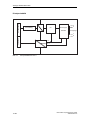
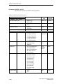
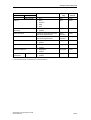
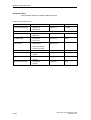
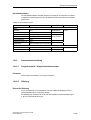
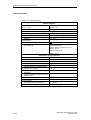
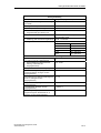
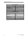
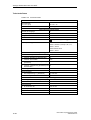
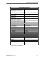
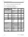
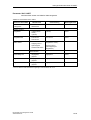
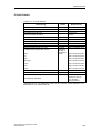
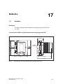
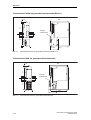
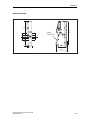
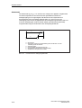
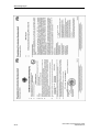
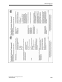
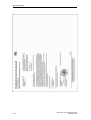
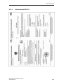
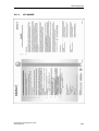
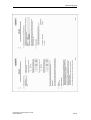
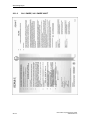
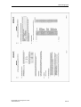
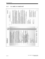
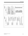
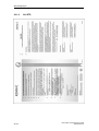
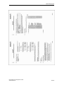
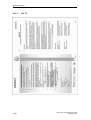
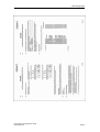
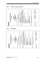
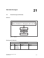
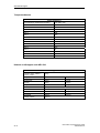
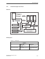
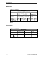
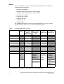
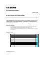
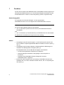
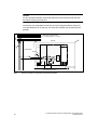
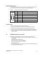
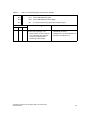
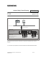
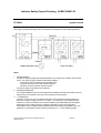
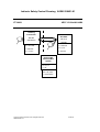
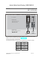
Intrinsic Safety Control Drawing A5E00158421-01
ET 200iS
6ES7 151-2AA00-0AB0
Not hazardous area
Associated Apparatus
Hazardous area
Isupply = 81 mA
Class I, DIV 2, GP A....D
Class I, Zone 1, IIC T4
Interface module IM 151-2
BSM 1
You can find the pin configuration in the manual „SIMATIC ET 200iS Distributed I/O Station“,
chapter 12.
Use with TM-IM/BSM P/N 6ES7 193-5DB00-0AA0.
The following parameters for the RS 485 fieldbus connection apply to the interface module:
Fieldbus
Uo, Voc [ Vdc ]
4,2
Isc, Io [ mA ]
100
Po, [ mW ]
106
Ui, Vmax [ Vdc ]
4,2 (*)
(*) Ii, Imax, Pi can be any value
The following merits apply to the fieldbus line:
Must be in accordance with NEC 504.30B:
•
L‘ / R‘
≤
22 µH / Ω (loopresistance)
•
C‘
≤
250 nF / km
•
Litz wire diameter ≤ 0,2 mm
•
Concentrated inductance and capacitance are not allowed in the running of the external RS
485 fieldbus system.
•
In applications where concentrated inductance and capacitance are considered the
following values apply: Co, Ca < 100 µF (A, B/IIC) or < 1000 µF (C, D/IIB)
and
Lo, La < 3mH (A, B/IIC) or < 15 mH (C, D/IIB)
Copyright 2004 by Siemens AG. All Rights Reserved
A5E00158421-01
5 of 13