1
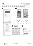
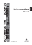
ATS1197 Smart card reader with keypad EN DE IT (protruding from the resin in the back of the RAS) when the RAS is in position. 8. Fix the RAS to the back plate using the two screws removed earlier from the bottom of the RAS. 9. Apply power to the control panel, or the 4-door DGP. 10. For online mode, use an LCD RAS on the BUS (or the system management software) to program polling and set up the required items for the new RAS. In particular, the ATS1197 RAS must be programmed as a non-LCD RAS. 11. Check that the ATS1197 is communicating correctly and verify that the tamper switch is working properly (i.e. "RAS Tamper" is not showing on the LCD RAS). WARNING: All power should be turned off to the control panel before wiring the RAS. Location of features (figure 1. 2. 3. 4. ) Red/Green dual colour LED. Yellow LED. Red LED. Locking screws. Connecting control panel to keypad RAS Refer to the ATS Control Panel Installation Guide for instructions. Tamper switch RAS 1 RAS 2 RAS 3 RAS 4 RAS 5 RAS 6 RAS 7 RAS 8 The ATS1197 tamper switch is closed when the unit is fitted on the mounting plate. In operation, the LCD display will show "RAS Tamper" when not closed. RAS DIP switch settings (figure EN RAS 9 RAS 10 RAS 11 RAS 12 RAS 13 RAS 14 RAS 15 RAS 16 ATS1197 Smart card reader with keypad ) A row of DIP switches is located on the rear of the RAS (figure ) and is used for setting the RAS address and the bus termination (TERM) condition. These settings are described in the following sections. 1. RAS address : Set the RAS address using switches 1 to 4. Switch in "UP" position is off, and switch in "DOWN" position is on. 2. TERM switch : Use switch 5 to set TERM to ‘ON’, if needed. There must be no more than two TERM switches or links set to ‘ON’ for any bus. Refer to the control panel installation guide for details about the use of TERM switches or links. ‘ON’ is indicated as black (down). Example: RAS 2 = On, off, off, off. Mounting the unit Connections 1. 2. Colour Application Red +12 V nominal (8.5 to 14.0 VDC supply) 3. 4. 5. 6. 7. Remove power to the control panel, or 4-door DGP, as applicable. Remove the two front panel screws at the bottom of the RAS (see Figure ), and then remove the RAS back plate. Retain the screws to secure the RAS later. Position the RAS back plate (with the tamper spring at the top) against the mounting surface to determine the locations of mounting holes and for cabling access (a reduced card reading range may occur if mounted on a metal surface). Mount the back plate on a flat surface using four screws (the hole nearest the tamper spring must have a screw in order for the tamper switch to work correctly). Terminate the cable, as required (see wiring details below). For on-line mode, set the BUS address (DIP switches 1 through 4). For on-line mode, set the TERM switch (DIP switch 5) as required. For off-line mode, the TERM switch must be off (up). See DIP switch settings for details. Mount the RAS on the back plate by engaging the top, and then lowering the RAS to be flat against the back plate. The rear tamper switch must be sealed for the system to work correctly. Ensure that the back plate tamper spring rests on the tamper switch actuator The RAS can be powered using the bus + and – power from the control panel if the distance between the RAS and the control panel does not exceed 100 m (328 feet). Otherwise the RAS can be powered by AUX PWR from a DGP, or by an auxiliary power supply. Black 0 V (DC supply ground) Green D0/D–/Clock, may be used for D0 (Wiegand data), D– (RS485 data), Magnetic stripe clock. Normal operating voltage 0 to +5 V (absolute maximum is +12 V). 2006 GE Security B.V. All rights reserved. www.gesecurity.net MAINST-ATS1197 Mar 2006 White Blue In offline mode, the TERM switch (DIP switch 5) must be ‘off’ (up). DIP switches 1 to 4 are not used in offline mode. D1/D+/Data, may be used for D1 (Wiegand data), D+ (RS485 data), magnetic stripe data. Normal operating voltage 0 to +5 V (absolute maximumis +12 V). The RAS is connected to the ATS panel via the RS485 data bus, up to 1.5 km from the control panel or the 4-door DGP. Use the 2-pair twisted, shielded data cable (WCAT52/54 is recommended). The shield of any bus cable must be connected to system ground at one end only. The ATS111x RAS is not provided with an Earth connection for this purpose. If the bus is ‘daisy-chained’ to the RAS, ensure that the shield of the cable is joined to provide continuity of data cable shield. Operating features Buzzer/Beeper, may be used for offline buzzer control. Power up Night light The reader will be dimly lit when enabled. Beeper tone Press and hold the * key while pressing the 1 key to raise the tone frequency or the 2 key to lower the tone frequency. Wire open or +5 to 12 V: buzzer off (absolute maximum is +14 V). Upon initial power up, the buzzer will sound two beeps indicating that the internal non-volatile memory is OK. All of the area LEDs may illuminate indicating that the system is armed. All areas must be disarmed in order to enable access to the installer programming menu options. Wire grounded (0 V): buzzer on. Brown Application depends on selection of RAS menu option 2 — offline LED control. See programming. Yellow Application depends on selection of RAS menu option 2 — offline LED control (see programming). When not used for two wire LED control, yellow wire may be used for Troubleshooting • RTE input when online to ATS, No LED display or keypad backlight: • connection to a simple push button for operation in RT Only mode, • Verify the +13.8 and 0 V wire connections on both the RAS and the power supply. • connection to a button for use in RTE + Arm/Disarm mode. Button should be connected to GND. See 10—RTE (Egress) Control. • Verify power output on the control panel, 4-door DGP, or external power supply. Violet General faults All three status LEDs are flashing: Open collector output, configurable as Door output, Tamper output, or magnetic stripe data present. This is a low current output and must not be used to directly energize high current door openers (absolute maximum is 14 V @ 50 mA). When using a door control relay, always place a suppression diode (e.g. a 1N4001) across the relay coil. Status LED indications (figure Verify the D+ and D- wire connections (may be reversed or open circuit). • Verify the address DIP switches of the RAS are set to the proper address. • Verify that the control panel or 4-door controller is polling the RAS address. The RAS does not respond to a Smart Card: ) Connected to ATS control panel or access control panel Green/Red (disarm/arm) • • The RAS may not be programmed correctly or card beep and LED flash may be disabled. Refer Programming for details. • The Smart Card may not be programmed for use with the particular system. Rx and Tx LED Indications Green: when all areas assigned to the RAS alarm group are disarmed or when screensaver is active. Flashing green when running on battery (mains power off) or during unlock time when area disarmed. Rx and Tx LEDs are provided on the circuit board to assist in fault diagnosis and are visible when the rear plastic cover is removed. Red: if all areas assigned to the RAS alarm group are armed. Flashing red during unlock time when area armed. Rx: The yellow Rx LED flashes to indicate polling data is being received on the system bus from the panel. If the LED does not flash, the control panel is not operational or the bus is faulty (usually cabling). Tx: The red Tx LED flashes to indicate the RAS is replying to polling from the control panel. If the Rx LED flashes but the Tx LED does not, the RAS is not programmed to be polled in the control panel or is addressed incorrectly. LED off: if at least one and less than all areas assigned to the RAS alarm group are armed. Yellow (ready) Active when all zones in areas assigned to the RAS are normal (or active if RAS configured as ATS1156). Configuring the ATS 1197 RAS Red (alarm) Flashing when any areas assigned to the RAS is in alarm state. To configure the RAS: • Press 19 [ENTER] followed by * 3 [ENTER. Connected to a Wiegand or Magnetic Stripe interface • Type the required RAS address (2 – 16) followed by [ENTER]. Green/Red • Select the RAS. • Disable the option ’LCD Arming Station’. • Enable the option ‘3 LED RAS’. Green: On when yellow wire is at 0 V. Red: On when brown wire is at 0 V. Yellow: On when yellow AND brown wire at 0 V. LED off: When yellow and brown wire are between 5 – 14 V. Yellow Not used Red Not used 2 • Programming map GE Security, RAS1197.V01 0-EXIT, Menu: Both yellow and brown wires grounded (0 V), LED 1 is on yellow. Not valid when used on GE Security products. For one-wire LED control, the brown wire controls LED 1 green-red dual colour. 2-LEDs off-line 0-Exit, Menu: Two wire Led Control *-Change, #-Exit 3-Valid Card Flash 0-Exit, Menu: Enabled *-Change, #-Exit 4-Night Light 0-Exit, Menu: Enabled *-Change, #-Exit • Grounded or 0 V, LED 1 green on. • +5 to 15 V: LED 1 red is on. • Open or high Z, or +2.5 V: LED 1 off. Menu 3, Valid card flash If enabled (default), the green LED will give one short flash when the card is badged. The panel controls subsequent flashes. Menu 4, Night light A dimly lit keypad backlight provides the night-light to easily locate the keypad in dark locations (enabled by default). Menu 5, Protocol options This option selects the method by which the reader sends data to the panel. The options are Wiegand (default) or Magnetic stripe. See option 16 for more data on transmitted data details. 5-Protocol Options 0-Exit, Menu: Wiegand *-Change, #-Exit 6-Card Beep 0-Exit, Menu: Enabled *-Yes, #-No 7-Watch Dog 0-Exit, Menu: Disabled *-Change, #-Exit Offline mode only. If enabled, one byte of data is sent to the host every minute to indicate that the RAS is connected and operating normally. If the ATS1197 tamper is active, the data byte will not be sent (disabled by default). 8-O/C Output 0-Exit, Menu: Door Output *-Change, #-Exit Menu 8, O/C output 9-Option Card 0-Exit, Menu: Enabled *-Change, #-Exit Menu 6, Card beep If enabled (default), the beeper will give a short beep when a card is badged. The panel controls subsequent beeper activity. Menu 7, Watchdog Select one of the following options: • Door relay (online mode only) — The open collector output activates (active low) when the door open signal is sent to the ATS1197 (default setting). • Tamper output (online or offline modes) — The open collector output activates (active low) when the ATS1197 Tamper is active. • Card data present (offline mode only) — The open collector output activates (active low) when the card data is being sent to the host. 10-RTE (Egress) 0-Exit, Menu: RTE Disabled *-Change, #-Exit 11-Factory Defaults 0-Exit, Menu: Set Defaults? *-Yes, #-No This option enables (default setting) and disables the use of reader configuration (option) cards at the reader. If an installer wishes to prevent the modification of the reader setup by configuration card, this option should be disabled. 13-Last Card 0-Exit, Menu: 00,00,00,00,00,00 #-Exit Menu 10, RTE (Egress) 16-Security Mode 0-Exit, Menu: Un-Secured Mode *-Change, #-Exit There are three options to choose from: Menu 9, Option card The RAS is fitted with Request To Exit (RTE) control (yellow wire). The open collector output (violet wire) may be used to control a door relay. RTE is only available in online mode. • RTE disabled. When RTE is not used, it is recommended to disable it. • RTE only. This option requires a simple push button to be connected to the yellow wire. A press of the button will release the door lock relay. Used for a quick exit from an Area (enabled by default). To enter the programming menu for the ATS1197: • RTE arm/disarm. Do not use. • Enter menu 28 of the control panel installer menu. Menu 11, Factory defaults • Press 2 [ENTER] followed by the RAS address selected and [ENTER] to enter the RAS menu. The display now shows "GE Security, RAS1197" followed by the version number. This option returns all RAS settings to the factory default condition. Reserved menus are not shown Programming options The ATS1197 provides for a menu through which a number of options can be set. • Menu 13, Last card This option displays the number of the last card badged on the reader, in the format: facility code/system code, ID number or as raw card data (depends on setting of security mode). Press [ENTER] to proceed to the menu or press the menu number followed by [ENTER] to go to a menu item directly. Menu 1, 12, 14 and 15 are reserved menus. Menu 16, Security mode Menu 2, LEDs offline This option selects the type of user card the reader will recognise. The reader will recognise configuration and default cards in both modes. The possible modes are as follows: Select either two-wire (default) or one-wire LED control. For two-wire LED control: • The brown wire controls LED 1 red (Arm). Wire grounded: LED 1 red on, wire open or at +5 to 14 V: LED 1 off. • The yellow wire controls the LED 1 green (Disarm). Wire grounded (0 V): LED 1 green on, wire open or at +5 to 14 V: LED 1 off. • 3 Unsecured mode (default setting) — The reader will recognise blank or un-programmed cards only, by using the card’s unique serial number. The 4-byte security password is not used. Unsecured mode requires the use of an expanded memory system. • Befestigungslöcher und der Verkabelung zu ermitteln (die Montage auf einer Oberfläche aus Metall kann zu einem reduzierten Kartenleseabstand führen). 4. Befestigen Sie die Rückplatte mit vier Schrauben an einer flachen Oberfläche (in das am nächsten zur Feder des Sabotagekontakts gelegene Loch muss eine Schraube eingesetzt werden, sodass der Schalter ordnungsgemäß arbeiten kann). 5. Schließen Sie das Kabel, wie erforderlich, ab (siehe Verkabelungsdetails weiter unten). 6. Für den Online-Modus stellen Sie die BUS-Adresse (DIP-Schalter 1 bis 4) ein. Für den Online-Modus stellen Sie den TERM-Schalter (DIPSchalter 5) nach Bedarf ein. Für den Offline-Modus muss der TERMSchalter ausgeschaltet sein (nach oben). Weitere Details finden Sie im Abschnitt mit den DIP-Schaltereinstellungen. 7. Befestigen Sie das BDT an der Rückplatte, indem Sie zunächst die obere Kante einsetzen und dann das BDT flach auf die Rückplatte aufsetzen. Damit das System ordnungsgemäß funktioniert, muss der rückwärtige Sabotageschalter geschlossen sein. Stellen Sie sicher, dass die Feder an der Rückplatte auf dem Auslöser des Sabotagekontakts aufliegt (der aus dem Kunstharz hinten im BDT austritt), wenn sich das BDT in Position befindet. 8. Befestigen Sie das BDT mit den beiden Schrauben an der Rückplatte, die Sie in Schritt 2 entfernt haben. 9. Verbinden Sie die Einbruchmeldezentrale oder den 4-Tür-Controller mit der Spannungsversorgung. 10. Für den Online-Modus verwenden Sie ein LCD-BDT auf dem BUS (oder die Managementsoftware des Systems), um die Abfrage zu programmieren und die erforderlichen Optionen für das neue BDT einzustellen. Wichtig: Das ATS1197-BDT muss als Nicht-LCD-BDT programmiert werden. 11. Überprüfen Sie, ob das ATS1197 ordnungsgemäß kommuniziert und stellen Sie sicher, dass der Sabotagekontakt richtig arbeitet (die Meldung "BDT-Sabotage" sollte nicht auf der LCD-BDT angezeigt werden). Secured mode — Only cards programmed on the ATS1620/1621/1622 programmer will be recognised in this mode. The 4-byte security password is used. Data transmission The following tables list the formats by which the card reader transmits data, as determined by: • whether the reader is used online or offline, and by • menu option 5—Protocol options (Wiegand or Magnetic stripe), and by • menu option 16—Security mode (secured or unsecured). In online mode, select ‘Wiegand’ in menu 5 to use 26 or 27 bit data, or select ‘Magnetic stripe’ to use 32 bit data. Online Card format Reader protocol Wiegand Magnetic stripe Secured When badged on a reader, 26 or 27 bit data is transmitted, depending on whether the card is programmed as Wiegand 26 bit or Aritech Wiegand ASC. When badged on a reader, 32 bit data is transmitted. Unsecured When an unsecured card is badged on a reader using the magnetic stripe format, 32 bit data is transmitted. Offline Card format Secured Unsecured Reader protocol Wiegand Magnetic stripe When badged on a reader, 26 or 27 bit data is transmitted, depending on whether the card is programmed as Wiegand 26 bit or Aritech Wiegand ASC. When badged on a reader, Magnetic stripe format data is transmitted. When badged on a reader using the Wiegand protocol, Aritech Wiegand ASC data is transmitted. When badged on a reader using the magnetic stripe protocol, Magnetic stripe data is transmitted. WARNUNG: Bevor mit der Verkabelung der BDT begonnen wird, muss die Spannungsversorgung zur Einbruchmeldezentrale unterbrochen werden. A "card present" signal is available on the relay output (violet wire), if selected in menu option 8 — Open collector output. Position der Funktionen (Abbildung 1. 2. 3. 4. 8.5 - 14.0 VDC max. Maximum operating current 110 mA @ 13.8 VDC Normal operating current (all areas armed) 40 mA @ 13.8 VDC Open Collector Output (OUT terminal) 14 VDC max. @ 50 mA max. Dimensions with cover (W x H x D) 140 x 121 x 22 mm Operating temperature -40 to +50°C Humidity 95% non condensing DE Anweisungen zu diesem Thema finden Sie im Installationshandbuch der ATS-Einbruchmeldezentrale. Sabotagekontakt Der ATS1197-Sabotagekontakt wird niedergedrückt, wenn das Gerät auf der Befestigungsplatte angebracht wird. Während des Betriebs zeigt die LCD-Anzeige "BDT-Sabotage" an, wenn der Schalter nicht niedergedrückt ist. BDT-DIP-Schaltereinstellungen (Abbildung 2. 3. ) Auf der Rückseite des BDT befindet sich eine Reihe von DIP-Schaltern (Abbildung ), die zur Einstellung der BDT-Adresse und der BusAbschlussbedingung (TERM) dienen. Diese Einstellungen werden in den folgenden Abschnitten beschrieben. 1. BDT-Adresse : Stellen Sie die BDT-Adresse mithilfe der Schalter 1 bis 4 ein. Der Schalter in der Position "NACH OBEN" ist ausgeschaltet, in der Position "NACH UNTEN" ist er eingeschaltet. 2. TERM-Schalter : Verwenden Sie Schalter 5, um den TERMSchalter bei Bedarf auf "EIN" zu stellen. Pro Busleitung dürfen nie mehr als zwei TERM-Schalter oder -Brücken auf "EIN" eingestellt sein. Nähere Informationen zur Verwendung der TERM-Schalter und -Brücken finden Sie im Installationshandbuch der ATSEinbruchmeldezentrale. ATS1197 Smart Card-Leser mit Tastatur Montage des Geräts 1. Zweifarbige LED (rot/grün). Gelbe LED. Rote LED. Sicherungsschrauben. Verbinden der Einbruchmeldezentrale mit der Tastatur des BDT Technical data Supply voltage ) Trennen Sie die Einbruchmeldezentrale oder den 4-Tür-Controller von der Spannungsversorgung. Entfernen Sie die beiden Schrauben für die Vorderseite unten an dem BDT (siehe Abbildung ) und nehmen Sie anschließend die BDT-Rückplatte ab. Legen Sie die Schrauben beiseite, um das BDT später zu sichern. Halten Sie die BDT-Rückplatte (mit der Feder des Sabotagekontakts nach oben) an die Montagestelle, um die Position der 4 "EIN" wird schwarz dargestellt (nach unten). Beispiel: BDT 2 = Ein, Aus, Aus, Aus. Rot: wenn alle der BDT-Alarmgruppe zugeordneten Bereiche scharfgeschaltet sind. Rot blinkend während der Entriegelungszeit, wenn der Bereich scharfgeschaltet ist. Verbindungen Farbe Anwendung Rot +12 V nominal (8.5 bis 14.0 V Gleichspannung) LED aus: wenn mindestens eine, aber nicht alle der BDTAlarmgruppe zugeordneten Bereiche scharfgeschaltet sind. Gelb (Bereit) Aktiv, wenn alle MG in den der BDT-Alarmgruppe zugeordneten Bereichen "geschlossen" sind (oder "gestört", wenn das BDT als ATS1156 konfiguriert wurde). Wenn der Abstand zwischen dem BDT und der Einbruchmeldezentrale 100 m nicht übersteigt, dann kann das BDT mithilfe der Datenbusverbindungen + und – von der Einbruchmeldezentrale mit Spannung versorgt werden. Verwenden Sie andernfalls den Anschluss AUX PWR von einer AME oder einer Nebenmelderversorgung. Schwarz 0 V (Gleichspannung) Grün D0/D–/Clock kann für D0 (Wiegand-Daten), D– (RS485Daten), Magnetstreifen-Clock verwendet werden. Normale Betriebsspannung 0 bis +5 V (absolutes Maximum +12 V). Weiß Rot (Alarm) Mit einer Wiegand- oder Magnetstreifenschnittstelle verbunden Grün/Rot Grün: "Ein", wenn die gelbe Ader auf 0 V geschaltet ist. Rot: "Ein", wenn die braune Ader auf 0 V geschaltet ist. Gelb: "Ein", wenn die gelbe UND die braune Ader auf 0 V geschaltet ist. D1/D+/Daten kann für D1 (Wiegand-Daten), D+ (RS485Daten), Magnetstreifendaten verwendet werden. Normale Betriebsspannung 0 bis +5 V (absolutes Maximum +12 V). LED Aus: Wenn sich die gelbe und braune Ader zwischen 5 – 14 V befinden. Das BDT wird über den RS485-Datenbus mit der ATSEinbruchmeldezentrale verbunden und kann bis zu 1.5 km von der Einbruchmeldezentrale oder 4-Tür-Controller-AME entfernt sein. Es wird die Verwendung des abgeschirmten, verdrillten 2-Adernpaars (WCAT 52/54) als Datenkabel empfohlen. Die Abschirmung der Buskabel darf nur an einem Ende mit der Systemerdung verbunden werden. Das BDT ATS111x besitzt keinen Erdungsanschluss, der zu diesem Zweck benutzt werden könnte. Wenn der Bus über eine Daisy-Chain-Verbindung an das BDT angeschlossen wird, müssen Sie sicherstellen, dass die Kabelabschirmungen miteinander verknüpft werden, damit die Datenkabelabschirmung nicht unterbrochen wird. Blau Gelb Nicht verwendet Rot Nicht verwendet Für den Offline-Modus muss der TERM-Schalter (DIP-Schalter 5) ausgeschaltet sein (nach oben). Dip-Schalter 1 bis 4 werden im Offline-Modus nicht verwendet. Betriebsfunktionen Nachtbeleuchtung Der Leser wird im aktivierten Zustand schwach beleuchtet. Signalton Summer kann für die Offline-Summersteuerung verwendet werden. Halten Sie die * Taste gedrückt und betätigen Sie die Taste 1, um die Tonfrequenz zu erhöhen oder betätigen Sie die Taste 2, um die Frequenz herabzusetzen. Ader offen oder an +5 V bis 12 V: Summer aus (absolutes Maximum +14 V). Einschalten Ader auf Minus (0 V): Summer ein. Braun Die Anwendung hängt von der Auswahl der BDTMenüoption 2, Offline-LED-Steuerung ab. Siehe "Programmierung". Gelb Die Anwendung hängt von der Auswahl der BDTMenüoption 2, Offline-LED-Steuerung ab. Siehe "Programmierung". Wenn nicht die 2-Draht LEDSteuerung verwendet wird, kann die gelbe Ader für folgende Zwecke verwendet werden: Nach dem Einschalten erzeugt der Summer zwei Signaltöne, um anzuzeigen, dass der interne permanente Speicher betriebsbereit (OK) ist. Möglicherweise leuchten sämtliche Bereichs-LEDs und zeigen damit die Scharfschaltung des Systems an. Die Bereiche müssen unscharfgeschaltet werden, damit auf die Optionen im Errichterprogrammiermenü zugegriffen werden kann. Fehlerbehebung Allgemeine Störungen Keine LED-Anzeige oder Hintergrundbeleuchtung für die Tastatur aktiviert: • Türöffner-Freigabe (T-F) bei ATS-Onlinebetrieb • Verbindung mit einer einfachen Taste ausschließlichen Betrieb im Türöffner-Modus für de • Verbindung mit einer Taste für die Verwendung im Türöffner- und Scharfschaltungs-/Entschärfungsmodus Die Taste sollte mit Minus verbunden sein. Siehe auch 10 – Türöffner (Türfreigabe)-Steuerung. Violett Blinkend, wenn sich einer der der BDT-Alarmgruppe zugeordneten Bereiche im Alarmzustand befindet. Überprüfen Sie sowohl am BDT als auch am Netzteil die Kabelverbindungen für +13.8 und 0 V Spannungsversorgung. • Überprüfen Sie den Spannungsausgang der Einbruchmeldezentrale, des 4-Tür-Controllers oder des externen Netzteils. Alle drei Status-LEDs blinken: Open-Collector-Ausgang, als Türausgang konfigurierbar, Sabotageausgang oder Magnetstreifendaten vorhanden. Hierbei handelt es sich um einen Ausgang mit geringer Schaltleistung, der nicht verwendet werden kann, um Türöffner mit hoher Stromaufnahme direkt zu aktivieren (absolutes Maximum 14 V @ 50 mA). Bei Verwendung einer Türrelaissteuerung schalten Sie eine Freilaufdiode (z.B. 1N4001) parallel zur Spule des Relais. LED-Statusanzeigen (Abbildung • • Überprüfen Sie die Kabelverbindungen D+ und D– (sie wurden möglicherweise vertauscht oder unterbrochen). • Überprüfen Sie, ob die DIP-Schalter für die BDT-Adresse die richtige Einstellung haben. • Stellen Sie sicher, dass die Einbruchmeldezentrale oder der 4-TürController die BDT-Adresse abfragen. Das BDT reagiert nicht auf eine Smart Card: • Das BDT wurde möglicherweise nicht richtig programmiert oder der Kartensignalton und das Blinken der LEDs wurde deaktiviert. Weitere Einzelheiten entnehmen Sie dem Abschnitt zur Programmierung. • Die Smart Card wurde möglicherweise nicht für die Verwendung mit diesem System programmiert. ) Verbunden mit ATS-Einbruchmeldezentrale oder 4-Tür-Controller Grün: wenn alle der BDT-Alarmgruppe zugeordneten Grün/Rot Bereiche unscharfgeschaltet sind oder wenn die Option (Unscharf"Bedienteil-LCD Anzeige sperrren" aktiv ist. Grün blinkend /Scharf) bei Batteriebetrieb (Netzausfall) oder während der Entriegelungszeit, wenn der Bereich unscharfgeschaltet ist. LED-Anzeigen Rx und Tx Die Rx- und Tx-LEDs auf der Leiterplatte sollen die Störungsdiagnose erleichtern; sie sind sichtbar, wenn die rückwärtige Kunststoffabdeckung entfernt wurde. 5 Rx: Tx: Die gelbe Rx-LED blinkt, um anzuzeigen, dass abgefragte Daten am Systembus von der ATS-Einbruchmeldezentrale empfangen werden. Wenn die LED nicht blinkt, ist die Einbruchmeldezentrale nicht funktionsfähig oder es liegt eine Störung am Datenbus vor (Verkabelung überprüfen). Die rote Tx-LED blinkt, um anzuzeigen, dass das BDT auf die Abfrage von der Einbruchmeldezentrale reagiert. Wenn die Rx-LED blinkt, die Tx-LED jedoch nicht, ist das BDT nicht für Abfragen durch die Einbruchmeldezentrale programmiert oder falsch adressiert. • Rufen Sie im Errichtermenü der Einbruchmeldezentrale das Menü 28 auf. • Drücken Sie 2 [ENTER], geben Sie dann die gewünschte BDTAdresse ein und drücken Sie [ENTER], um das BDT-Menü zu öffnen. Auf der Anzeige wird "GE Security, BDT1197" und nachfolgend die Versionsnummer angezeigt. • Drücken Sie [ENTER], um das betreffende Menü anzuzeigen, oder geben Sie die Menünummer ein und drücken Sie [ENTER], um eine Menüoption direkt aufzurufen. Konfigurieren des ATS 1197 BDT Menü 1, 12, 14 und 15 sind reservierte Menüs. So konfigurieren Sie das BDT: Menü 2, LEDs offline • Drücken Sie 19 [ENTER] gefolgt von * 3 [ENTER]. • Geben Sie die erforderliche BDT-Adresse (2 – 16) gefolgt von [ENTER] ein. Wählen Sie entweder die 2-Draht Steuerung. • Wählen Sie das BDT aus. • Deaktivieren Sie die Option "LCD-Schalteinrichtung". • Aktivieren Sie die Option "3 LED-BDT". Für die 2-Draht LED-Steuerung: Programmierübersicht GE Security, BDT1197.V01 0-ENDE, Menü: 2-LEDs off-line 0-Ende, Menü: (Standard) oder 1-Draht LED- • Der braune Ader steuert die LED 1 rot (scharf). Ader auf Minus (0 V): LED 1 rot ein, Ader offen oder an +5 bis 14 V: LED 1 aus. • Die gelbe Ader steuert die LED 1 grün (unscharf). Ader auf Minus (0 V): LED 1 grün ein, Ader offen oder an +5 bis 14 V: LED 1 aus. • Gelbe und braune Ader auf Minus (0 V), LED 1 leuchtet gelb. Nicht zulässig bei Verwendung mit GE Security-Produkten. Bei der 1-Draht LED-Steuerung steuert die braune Ader die zweifarbige LED 1 (grün/rot). Zweidraht LED Steuerung *-Ändern, #-Ende 3-Gültige Karte Blinkend 0-Ende, Menü: Freigegeben *-Ändern, #-Ende 4-Nachtlicht 0-Ende, Menü: Freigegeben *-Ändern, #-Ende 5-Protokoll Optionen 0-Ende, Menü: Wiegand *-Ändern, #-Ende 6-Karte Signalton 0-Ende, Menü: Freigegeben *-Ja, #-Nein 7-Watch Dog 0-Ende, Menü: Abgeschaltet *-Ändern, #-Ende 8-O/C Ausgang 0-Ende, Menü: Türausgang *-Ändern, #-Ende 9-Options Karte 0-Ende, Menü: Freigegeben *-Ändern, #-Ende 10-A-T (Türfreigabe) 0-Ende, Menü: A-T Abgeschaltet *-Ändern, #-Ende • Ader auf Minus (0 V), LED 1 grün ein. • Ader an +5 bis 15 V: LED 1 rot ist aktiv. • Offen oder Ader an +2.5 V: LED 1 aus. Menü 3, Anzeige "Gültige Karte blinkend" Bei aktivierter Option (Standard) blinkt die grüne LED kurz, wenn die Karte vor den Leser gehalten wird. Das Bedienfeld steuert aufeinander folgendes Blinken. Menü 4, Nachtlicht Eine schwache Tastatur-Hintergrundbeleuchtung dient als Nachtlicht, damit man das Bedienteil in einer dunklen Umgebung leicht finden kann (standardmäßig aktiviert). Menü 5, Protokolloptionen Mit dieser Option wird die Methode ausgewählt, die vom Leser zum Senden der Daten zur Einbruchmeldezentrale verwendet wird. Die Optionen lauten Wiegand (Standard) oder Magnetstreifen. Unter Option 16 finden Sie weitere Informationen zur Datenübertragung. Menü 6, Kartensignalton Bei aktivierter Option (Standard) gibt der Summer einen kurzen Signalton aus, wenn eine Karte vor den Leser gehalten wird. Das Bedienfeld steuert aufeinander folgende Signaltöne. Menü 7, Watchdog Nur im Offline-Modus. Bei aktivierter Option wird jede Minute ein Datenbyte an den Host gesendet, um zu signalisieren, dass das BDT angeschlossen ist und normal arbeitet. Wenn der ATS1197Sabotagekontakt aktiv ist, wird das Datenbyte nicht gesendet (standardmäßig deaktiviert). Menü 8, O/C-Ausgang Wählen Sie eine der folgenden Optionen: • Türrelais (nur Online-Modus) – Der Open-Collector-Ausgang wird aktiviert (LOW-aktiv), wenn das Signal zum Türöffnen an das ATS1197 gesendet wird (Standardeinstellung). • Sabotageausgang (Online- oder Offline-Modus) – Der OpenCollector-Ausgang wird aktiviert (LOW-aktiv), wenn der ATS1197Sabotagekontakt aktiv ist. Kartendaten vorhanden (nur Offline-Modus) – Der Open-CollectorAusgang wird aktiviert (LOW-aktiv), wenn die Kartendaten an den Host gesendet werden. 11-Werkseinstellungen 0-Ende, Menü: Werkseinstellung Laden ? *-Ja, #-Nein 13-Letzte Karte 0-Ende, Menü: 00,00,00,00,00,00 #-Ende • 16-Sicherheitsmodus 0-Ende, Menü: Ungesicherter Modus *-Ändern, #-Ende Menü 9, Optionskarte Mit dieser Option wird die Verwendung von Leserkonfigurationskarten (optionale Karten) am Leser aktiviert (Standardeinstellung) und deaktiviert. Diese Option sollte deaktiviert werden, wenn unterbunden werden soll, dass die Lesereinrichtung durch Konfigurationskarten verändert werden kann. Reservierte Menüs werden nicht angezeigt. Programmieroptionen Das ATS1197 stellt ein Menü zur Verfügung, über das eine Reihe von Optionen eingestellt werden können. So öffnen Sie das Programmiermenü für das ATS1197: 6 Menü 10, Türöffner (Türfreigabe) verfügbar (violette Ader), wenn dies in Menü 8, Open-Collector-Ausgang ausgewählt wurde. Das BDT ist mit einer Türfreigabe (T-F)-Steuerung ausgestattet (gelbe Ader). Der Open-Collector-Ausgang (violette Ader) kann zur Steuerung eines Türrelais verwendet werden. Der Türöffner ist nur im Online-Modus verfügbar. Ungesichert Wird die Karte einem Leser unter Verwendung des Wiegand-Protokolls vorgehalten, werden Aritech Wiegand ASCDaten übermittelt. Es stehen drei Optionen zur Auswahl: • Türöffner deaktiviert. Wenn der Türöffner nicht verwendet wird, sollte er deaktiviert werden. • Nur Türöffner. Diese Option erfordert, dass eine einfache Taste an der gelben Ader angeschlossen wird. Bei Betätigung der Taste wird das Türsperrrelais entriegelt. Wird zum schnellen Austritt aus einem Bereich verwendet (standardmäßig aktiviert). • Türöffner Scharf/Unscharf. Nicht verwenden. Wird die Karte einem Leser unter Verwendung des Magnetstreifenprotokolls vorgehalten, werden Magnetstreifendaten übermittelt. Technische Daten Menü 11, Werkseinstellungen Versorgungsspannung 8.5 - 14.0 VDC max. Mit dieser Option werden sämtliche BDT-Einstellungen auf die Werkseinstellungen zurückgesetzt. Maximale Stromaufnahme 110 mA @ 13.8 VDC Typische Stromaufnahme (alle Bereiche scharfgeschaltet) 40 mA @ 13.8 VDC Menü 13, Letzte Karte 14 VDC max. @ 50 mA max. Open-Collector-Ausgang OUT-Anschluss) Abmessungen mit Abdeckung (L x 140 x 121 x 22 mm H x T) Diese Option zeigt die Nummer der Karte, die zuletzt am Leser vorgehalten/gelesen wurde, in folgendem Format an: Einrichtungscode/Systemcode, ID-Nummer oder als Kartenrohdaten (abhängig von der Einstellung des Sicherheitsmodus). Menü 16, Sicherheitsmodus Betriebstemperatur -40 to +50°C Mit dieser Option wird der Typ der Benutzerkarte ausgewählt, der vom Leser erkannt wird. Der Leser erkennt in beiden Modi Konfigurations- und Werkskarten. Folgende Modi sind verfügbar: Luftfeuchtigkeit 95% (nichtkondensierend) • Ungesicherter Modus (Standard) - Der Leser erkennt anhand der eindeutigen Seriennummer der Karte nur leere oder nicht programmierte Karten. Das 4 Byte lange Sicherheitspasswort wird nicht verwendet. Dieser Modus erfordert den Einsatz eines Systems mit erweitertem Speicher (IUM). • Gesicherter Modus - In diesem Modus werden nur Karten erkannt, die mit dem ATS1620/1621/1622-Programmiergerät programmiert wurden. Es wird das 4 Byte lange Sicherheitspasswort verwendet. IT Montaggio dell'unità 1. Scollegare la centrale (o il concentrare a 4 varchi) dall'alimentazione. 2. Rimuovere le due viti del pannello frontale nella parte inferiore della RAS (vedere la figura ), quindi rimuovere la piastra posteriore della RAS. Conservare le viti per richiudere correttamente la RAS al termine dell'operazione. 3. Posizionare la piastra posteriore della RAS (con la molla antimanomissione in cima) sulla superficie di montaggio per definire le posizioni dei fori di montaggio e di accesso dei cavi. Il montaggio del dispositivo su una superficie metallica può comportare una riduzione della portata di lettura. 4. Fissare la piastra posteriore su una superficie piana utilizzando quattro viti. Per il corretto funzionamento dell'interruttore antimanomissione, il foro più vicino alla molla antimanomissione deve essere occupato da una vite. 5. Terminare il cavo in base alle esigenze (vedere più avanti i dettagli sul cablaggio). 6. Per la modalità in linea, impostare l'indirizzo del BUS (commutatori DIP switch da 1 a 4). Per la modalità in linea, impostare l'interruttore TERM (commutatore DIP switch 5) in base alle esigenze. Per la modalità fuori linea, disattivare l'interruttore TERM (in alto). Vedere la sezione relativa alle impostazioni dei commutatori DIP switch per i dettagli. 7. Montare la RAS sulla piastra posteriore inserendo la parte superiore e abbassando poi il corpo della RAS fino a farlo aderire alla piastra posteriore. L'interruttore antimanomissione posteriore deve essere sigillato perché il sistema funzioni correttamente. Verificare che la molla antimanomissione della piastra posteriore poggi sull'attuatore dell'interruttore antimanomissione (che sporge dalla resina sul retro della RAS) una volta collocata la RAS in posizione. 8. Fissare la RAS alla piastra posteriore utilizzando le due viti precedentemente rimosse dalla parte inferiore della RAS. 9. Collegare la centrale (o il concentrare a 4 varchi) all'alimentazione. 10. Per la modalità in linea, utilizzare una RAS LCD sul BUS (o il software di gestione del sistema) per programmare l'interrogazione e selezionare le necessarie impostazioni per la nuova RAS. In particolare, la RAS ATS1197 deve essere programmata come RAS non LCD. 11. Verificare che le comunicazioni dell'ATS1197 e l'interruttore antimanomissione funzionino correttamente (es. non venga visualizzata l'indicazione di manomissione RAS sulla RAS LCD). Datenübertragung In den folgenden Tabellen werden die Formate aufgelistet, die der Kartenleser zum Übertragen von Daten verwendet. Die Formate werden durch folgende Faktoren beeinflusst: • Online- oder Offline-Modus des Lesers, • Menü 5, Protokolloptionen (Wiegand oder Magnetstreifen), • Menü 16, Sicherheitsmodus (Gesichert oder Ungesichert). Wählen Sie im Online-Modus die Option "Wiegand" im Menü 5, um 26- oder 27-Bit-Daten zu verwenden oder wählen Sie "Magnetstreifen", um 32-Bit-Daten zu verwenden. Online Kartenformat Leserprotokoll Wiegand Magnetstreifen Gesichert Wird die Karte einem Leser vorgehalten, werden 26oder 27-Bit-Daten übertragen, je nachdem, ob die Karte als Wiegand 26Bit oder Aritech Wiegand ASC programmiert wurde. Wird die Karte einem Leser vorgehalten, werden 32-Bit-Daten übertragen. Ungesichert Wird einem Leser eine ungesicherte Karte unter Verwendung des Magnetstreifenformats vorgehalten, werden 32-Bit-Daten übertragen. Offline Kartenformat Gesichert Leserprotokoll Wiegand Magnetstreifen Wird die Karte einem Leser vorgehalten, werden 26oder 27-Bit-Daten übertragen, je nachdem, ob die Karte als Wiegand 26-Bit oder Aritech Wiegand ASC programmiert wurde. Wird die Karte einem Leser vorgehalten, werden Magnetstreifendaten übertragen. ATS1197 Lettore di smart card con tastiera Am Relaisausgang ist ein "Karte gelesen"-Signal 7 IMPORTANTE: Escludere l'alimentazione dalla centrale prima di procedere al cablaggio della RAS. Posizione degli elementi (figura 1. 2. 3. 4. Marrone L'applicazione dipende dalla scelta dell'opzione di menu 2 della RAS - Controllo LED fuori linea. Vedere la sezione relativa alla programmazione. Giallo L'applicazione dipende dalla scelta dell'opzione di menu 2 della RAS - Controllo LED fuori linea. Vedere la sezione relativa alla programmazione. Quando non utilizzato per il controllo LED a due cavi, il cavo giallo può essere utilizzato per le seguenti applicazioni: ) LED a doppio colore rosso/verde. LED giallo. LED rosso. Viti di fissaggio. • Ingresso RU quando in linea con l'ATS • Collegamento a un semplice pulsante funzionamento nella modalità solo RU Collegamento della centrale alla tastiera della RAS • Collegamento a un pulsante per l'utilizzo in modalità RU Inserimento/disinserimento. Il pulsante deve essere collegato a terra. Vedere il menu 10 - richiesta uscita (Egress). Per le istruzioni sul collegamento, consultare la guida all'installazione della centrale ATS. Interruttore antimanomissione Violetto L'interruttore antimanomissione dell'ATS1197 è chiuso quando l'unità viene collocata sulla piastra di montaggio. A dispositivo funzionante, sul display LCD verrà visualizzata l'indicazione di manomissione della RAS quando l'interruttore non è chiuso. Uscita open collector, configurabile come uscita varco, uscita manomissione o dati banda magnetica presenti. È un'uscita a bassa corrente e non deve essere utilizzata per alimentare direttamente i dispositivi di apertura varchi a corrente elevata (massimo assoluto 14 V a 50 mA). Quando si utilizza un relè di controllo varco, posizionare sempre un diodo antidisturbo (es. 1N4001) sulla bobina del relè. Impostazione dei commutatori DIP switch della RAS (figura ) Nella parte posteriore della RAS è presente una fila di commutatori DIP switch (figura ) che consentono di impostare l'indirizzo della RAS e la condizione della terminazione del bus (TERM). Tali impostazioni sono descritte nelle sezioni seguenti. 1. Indirizzo della RAS : Impostare l'indirizzo della RAS utilizzando gli interruttori da 1 a 4. Gli interruttori posizionati in alto sono disattivati, se posizionati in basso sono attivati. 2. Interruttore TERM : Se necessario, utilizzare l'interruttore 5 per impostare TERM su ON. Per ciascun bus non devono esserci più di due connessioni o interruttori TERM impostati su ON. Per i dettagli sull'uso delle connessioni o degli interruttori TERM, consultare la guida all'installazione della centrale. Indicatori LED di stato (figura ) Collegamento alla centrale ATS o alla centrale accessi Verde quando tutte le aree assegnate al gruppo di Verde/rosso (disinserimento/ allarmi della RAS sono disinserite o quando è attivo lo screen-saver. Verde lampeggiante durante il inserimento) funzionamento a batteria (alimentazione di rete disattivata) o durante il tempo di sblocco quando l'area è disinserita. Rosso se tutte le aree assegnate al gruppo di allarmi della RAS sono inserite. Rosso lampeggiante durante il tempo di sblocco quando l'area è inserita. ON è indicato dal colore nero (posizione in basso). Esempio: RAS 2 = On, Off, Off, Off. LED spento se è inserita almeno una delle aree (ma non tutte) assegnate al gruppo di allarmi della RAS. Collegamenti Colore Applicazione Rosso +12 V nominale (da 8.5 a 14.0 V) La RAS può utilizzare l'alimentazione + e – del bus della centrale, se la distanza tra RAS e centrale non supera i 100 m. In caso contrario, può essere alimentata tramite AUX PWR da un concentratore o da un alimentatore ausiliario. Nero 0 V (messa a terra ) Verde D0/D– /Clock, utilizzabile per D0 (dati Wiegand), D– (dati RS485) o clock banda magnetica. Tensione normale di funzionamento da 0 a +5 V (massimo assoluto +12 V). Bianco Giallo (pronto) Attivo quando tutte le zone delle aree assegnate alla RAS sono normali (o attivo se la RAS è configurata come ATS1156). Rosso (allarme) Lampeggiante quando una o più aree assegnate alla RAS si trovano in stato di allarme. Collegamento a un'interfaccia in formato Wiegand o a banda magnetica Verde/rosso Verde: Acceso quando il cavo giallo è a 0 V. Rosso: Acceso quando il cavo marrone è a 0 V. Giallo: Acceso quando il cavo giallo e marrone è a 0 V. LED spento: Quando i cavi giallo e marrone sono tra 5 e 14 V. D1/D+ /Dati, utilizzabile per D1 (dati Wiegand), D+ (dati RS485) o dati banda magnetica. Tensione normale di funzionamento da 0 a +5 V (massimo assoluto +12 V). Giallo La RAS è collegata alla centrale ATS tramite il bus dati RS485, fino a una distanza massima di 1,5 km dalla centrale (o dal concentratore a 4 varchi). Si raccomanda l'uso di cavi dati schermati a doppia coppia twistata (WCAT52/54). Gli schermi dei cavi del bus devono essere collegati a terra per una sola estremità. La RAS ATS111x non è provvista di connessione a terra per questo scopo. Se il bus è configurato in cascata con la RAS, verificare che lo schermo del cavo dati sia collegato in modo da garantirne la continuità. Blu per Non utilizzato Rosso Non utilizzato Nella modalità fuori linea, disattivare l'interruttore TERM (commutatore DIP switch 5 in alto). I commutatori DIP switch da 1 a 4 non vengono utilizzati nella modalità fuori linea. Caratteristiche Luce notturna Se questa funzione è attivata, il lettore sarà debolmente illuminato. Tono del segnale acustico Cicalino/segnale acustico, può essere utilizzato per il controllo fuori linea del cicalino. Premere e tenere premuto il tasto * mentre si preme il tasto 1 per aumentare la frequenza del tono o il tasto 2 per ridurla. Cavo aereo o da +5 V a +12 V: cicalino disattivato (massimo assoluto +14 V). Accensione Cavo interrato (0 V): cicalino attivato. All'accensione iniziale, vengono emessi due segnali acustici per indicare che la memoria interna non volatile funziona correttamente. È possibile che si accendano tutti i LED di area, a indicare che il sistema è inserito. 8 Tutte le aree devono essere disinserite per poter accedere alle opzioni di menu per la programmazione. Mappa di programmazione GE Security, RAS1197.V01 0-EXIT, Menu: Risoluzione dei problemi Guasti generali Nessuna visualizzazione LED o retroilluminazione della tastiera: • Verificare le connessioni +13.8 e 0 V sulla RAS e sull'alimentatore. • Verificare l'uscita alimentazione sulla centrale, sul concentratore a 4 varchi o sull'alimentatore esterno. Tutti e tre i LED lampeggiano: • Verificare le connessioni D+ e D- (potrebbero essere invertite o il circuito potrebbe essere aperto). • Verificare che i commutatori DIP switch dell'indirizzo della RAS siano correttamente impostati. • Verificare che la centrale o il concentratore a 4 varchi stiano interrogando l'indirizzo RAS. La RAS non risponde a una smart card: • • È possibile che la RAS sia stata programmata in modo non corretto o che il segnale acustico delle tessere e il lampeggiamento dei LED siano stati disattivati. Consultare la sezione relativa alla programmazione. È possibile che la smart card non sia stata programmata per l'uso con lo specifico sistema. LED Rx e Tx 2-LEDs off-line 0-Exit, Menu: Two wire Led Control *-Change, #-Exit 3-Valid Card Flash 0-Exit, Menu: Enabled *-Change, #-Exit 4-Night Light 0-Exit, Menu: Enabled *-Change, #-Exit 5-Protocol Options 0-Exit, Menu: Wiegand *-Change, #-Exit 6-Card Beep 0-Exit, Menu: Enabled *-Yes, #-No 7-Watch Dog 0-Exit, Menu: Disabled *-Change, #-Exit 8-O/C Output 0-Exit, Menu: Door Output *-Change, #-Exit 9-Option Card 0-Exit, Menu: Enabled *-Change, #-Exit 10-RTE (Egress) 0-Exit, Menu: RTE Disabled *-Change, #-Exit 11-Factory Defaults 0-Exit, Menu: Set Defaults? *-Yes, #-No 13-Last Card 0-Exit, Menu: 00,00,00,00,00,00 #-Exit 16-Security Mode 0-Exit, Menu: Un-Secured Mode *-Change, #-Exit I LED Rx e Tx, visibili sulla scheda dei circuiti quando il coperchio posteriore di plastica viene rimosso, semplificano la diagnosi dei guasti. Rx: Tx: Il LED giallo Rx lampeggia per indicare la ricezione dei dati di interrogazione inviati dalla centrale al bus del sistema. Se il LED non lampeggia, la centrale non è operativa oppure il bus è guasto (generalmente si tratta di un problema di cablaggio). Il LED rosso Tx lampeggia per indicare la risposta della RAS all'interrogazione inviata dalla centrale. Se il LED Rx lampeggia ma il LED Tx no, la RAS non è programmata per l'interrogazione nella centrale o l'indirizzo impostato non è corretto. Configurazione della RAS ATS 1197 Per configurare la RAS: • Premere 19 [ENTER] seguito da * 3 [ENTER]. • Digitare l'indirizzo della RAS richiesto (2-16) e premere [ENTER]. • Selezionare la RAS. • Disattivare l'opzione "LCD Arming Station". • Attivare l'opzione "3 LED RAS". I menu riservati non sono mostrati nella figura. Opzioni di programmazione L'ATS1197 ha un menu che consente di impostare diverse opzioni. Per accedere al menu di programmazione dell'ATS1197: • Accedere al menu 28 del menu Tecnico della centrale. • Premere 2 [ENTER] seguito dall'indirizzo della RAS selezionato, quindi [ENTER] per accedere al menu della RAS. Sul display viene ora visualizzata l'indicazione "GE Security, RAS1197" seguita dal numero di versione. • Premere [ENTER] per passare al menu, oppure premere il numero del menu seguito da [ENTER] per andare direttamente a una voce di menu. I menu 1, 12, 14 e 15 sono riservati. Menu 2, LED fuori linea Selezionare il controllo LED su due cavi (impostazione predefinita) o su un cavo. Per il controllo LED su due cavi: • 9 Il cavo marrone controlla il LED 1 rosso (inserimento). Cavo interrato: LED 1 rosso acceso; cavo aereo o a +5 V/+14 V: LED 1 spento. • Il cavo giallo controlla il LED 1 verde (disinserimento). Cavo interrato (0 V): LED 1 verde acceso; cavo aereo o a +5 V/+14 V: LED 1 spento. • Cavi giallo e marrone interrati (0V), LED 1 giallo acceso. Non valido quando utilizzato su prodotti GE Security. Menu 16, modalità sicurezza Questa opzione consente di selezionare il tipo di tessera utente che verrà riconosciuto dal lettore. Il lettore riconoscerà le tessere predefinite e le schede di configurazione in entrambe le modalità. Le modalità disponibili sono le seguenti: Per il controllo LED su un cavo, il cavo marrone controlla il LED 1 a doppio colore verde/rosso. • Interrato o 0V, LED 1 verde acceso. • Da +5 a 15 V: LED 1 rosso acceso. • Aperto o impedenza High-Z, o +2.5 V: LED 1 spento. Menu 3, lampeggiamento tessera valida Se l'opzione è attivata (impostazione predefinita), il LED verde emette un unico lampeggiamento breve quando una tessera viene avvicinata al lettore. La centrale controlla i lampeggiamenti successivi. • Modalità non sicura (impostazione predefinita): il lettore riconosce esclusivamente le tessere vuote o non programmate, utilizzando il numero di serie univoco della tessera. Non viene utilizzata la password di sicurezza a 4 byte. La modalità non sicura richiede l'uso di un sistema di memoria espansa. • Modalità sicura: solo le schede programmate sul programmatore ATS1620/1621/1622 vengono riconosciute in questa modalità. Viene utilizzata la password di sicurezza a 4 byte. Trasmissione dei dati Menu 4, illuminazione notturna Nella tabella seguente sono riportati i formati utilizzati dal lettore per la trasmissione dei dati, in base alle seguenti condizioni: Una leggera retroilluminazione semplifica l'individuazione della tastiera in ambienti bui (opzione attivata per impostazione predefinita). Menu 5, opzioni di protocollo Questa opzione consente di selezionare la modalità di invio dati dal lettore alla centrale. Le opzioni disponibili sono Wiegand (impostazione predefinita) o banda magnetica. Vedere l'opzione 16 per ulteriori informazioni sui dettagli dei dati trasmessi. • Utilizzo del lettore in modalità in linea o fuori linea • Opzione di menu 5 - opzioni di protocollo (Wiegand o banda magnetica) • Opzione di menu 16 - modalità sicurezza (sicura o non sicura). Nella modalità in linea, selezionare l'opzione Wiegand nel menu 5 per utilizzare i dati a 26 o 27 bit, oppure l'opzione Banda magnetica per utilizzare i dati a 32 bit. Menu 6, segnale acustico tessera Se l'opzione è attivata (impostazione predefinita), viene emesso un breve segnale acustico quando una tessera viene avvicinata al lettore. La centrale controlla i lampeggiamenti successivi. In linea Formato tessera Wiegand Banda magnetica Sicura Quando si avvicina una tessera al lettore, vengono trasmessi i dati a 26 o 27 bit, in base al formato di programmazione della tessera (Wiegand 26 bit o Aritech Wiegand ASC). Quando si avvicina una tessera al lettore, vengono trasmessi i dati a 32 bit. Non sicura Quando si avvicina una tessera al lettore utilizzando il formato banda magnetica, vengono trasmessi i dati a 32 bit. Menu 7, watch-dog Sono in modalità fuori linea. Se l'opzione è attivata, all'host viene inviato un byte di dati al minuto per indicare che la RAS è collegata e funziona correttamente. Se la protezione antimanomissione dell'ATS1197 è attiva, il byte di dati non verrà inviato (opzione disattivata per impostazione predefinita). Menu 8, uscita A/C Selezionare una delle opzioni seguenti: • Relè varco (solo modalità in linea): l'uscita open collector si attiva (attiva bassa) quando il segnale di varco aperto viene inviato all'ATS1197 (impostazione predefinita). • Protezione antimanomissione (modalità in linea e fuori linea): l'uscita open collector si attiva (attiva bassa) quando la protezione antimanomissione dell'ATS1197 è attiva. • Protocollo lettore Fuori linea Formato tessera Dati tessera presenti (solo modalità fuori linea): l'uscita open collector si attiva (attiva bassa) quando i dati della tessera vengono inviati all'host. Sicura Menu 9, opzioni tessera Questa opzione consente di attivare (impostazione predefinita) o disattivare l'uso delle schede opzionali di configurazione sul lettore. Per impedire la modifica delle impostazioni del lettore tramite scheda di configurazione, disattivare questa opzione. Menu 10, richiesta uscita (Egress) Protocollo lettore Wiegand Banda magnetica Quando si avvicina una tessera al lettore, vengono trasmessi i dati a 26 o 27 bit, in base al formato di programmazione della tessera (Wiegand 26 bit o Aritech Wiegand ASC). Quando si avvicina una tessera al lettore, vengono trasmessi i dati in formato banda magnetica. Quando si avvicina una tessera al lettore utilizzando il protocollo Wiegand, vengono trasmessi i dati Aritech Wiegand ASC. Quando si avvicina una tessera al lettore utilizzando il protocollo banda magnetica, vengono trasmessi i dati banda magnetica. La RAS è dotata del controllo Richiesta uscita (RU, cavo giallo). È possibile utilizzare l'uscita open collector (cavo violetto) per controllare il relè di un varco. La richiesta uscita (RU) è disponibile solo in modalità in linea. Sono disponibili tre opzioni: • RU disattivata. Quando la RU non è utilizzata, si consiglia di disattivarla. • Solo RU. Questa opzione richiede il collegamento di un semplice pulsante al cavo giallo. Premendo il pulsante, il relè di blocco del varco viene rilasciato. Utilizzato per un'uscita rapida dall'area (attivo per impostazione predefinita). • Inserimento/disinserimento RU. Da non usare. Non sicura Se è selezionata l'opzione di menu 8 uscita open collector, sull'uscita relè (cavo violetto) è disponibile un segnale di “tessera presente”. Dati tecnici Menu 11, impostazioni predefinite Questa opzione ripristina tutte le impostazioni predefinite della RAS. Menu 13, ultima tessera Questa opzione consente di visualizzare il numero dell'ultima tessera avvicinata al lettore nel seguente formato: codice di sistema, numero ID o dati tessera (in base alle impostazioni della modalità sicurezza). 10 Voltaggio di alimentazione 8.5 - 14.0 V max. Corrente massima di funzionamento 110 mA @ 13.8 V Corrente normale di funzionamento (tutte le aree inserite) 40 mA @ 13.8 V Uscita open collector (terminale OUT) 14 V max. @ 50 mA max. Dimensioni con coperchio (L x A x P) 140 x 121 x 22 mm Temperatura di funzionamento -40 to +50°C Umidità 95% senza condensa 11 MANUFACTURERS DECLARATION OF CONFORMITY For Product identification: Model/type Category (description) Brand : ATS1197 BOM revision level :E : Non LCD, Remote Arming Station, with Card Reader and keypad : GE Security Manufacturer: GE Security 646 Whitehorse Road Mitcham, 3132 Australia EU Representative: GE Security B.V. Kelvinstraat 7 6003 DH Weert The Netherlands Concerning RTTE EMC EMC Technologies Pty Ltd 57 Assembly Drive Tullamarine, 3043 Victoria Australia A sample of the product has been tested by: Test report reference M040929-1 Applied standards EN50130-4 :1995 +A1 :1995 Safety GE Security 646 Whitehorse Road Mitcham, 3132 Australia Radio EMC Technologies Pty Ltd 57 Assembly Drive Tullamarine, 3043 Victoria Australia IEC 60950 Test Report For ATS1197 EN60950(2000) M040929-2 EN300330-2 v1.1.1 (06-2001) Equipment class identifier (RF products falling under the scope of R&TTE) Not Applicable X None (class 1 product) (class 2 product) Means of conformity We declare under our sole responsibility that this product is in conformity with Directive 93/68/EEC (Marking) and/or complies to the essential requirements and all other relevant provisions of the 1999/5/EC (R&TTE) based on test results using harmonized standards in accordance with the Directives mentioned.