1
®
V9645D
DATA AND TECHNICAL SPECIFICATIONS MAY BE CHANGED AT ANY TIME WITHOUT NOTICE THEREOF.
LES DONNEES ET LES CARACTERISTIQUES TECHNIQUES PEUVENT SUBIR DES VARIATIONS A TOUT MOMENT ET SANS PREAVIS.
TECHNISCHE ÄNDERUNGEN JEDERZEIT OHNE VORHERIGE ANKÜNDIGUNG MÖGLICH.
DADOS E CARACTERISTICAS TÉCNICAS PODEM SER VARIADOS EM QUALQUER MOMENTO SEM AVISO PRÉVIO.
®
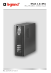
UNINTERRUPTIBLE POWER SUPPLIES
ONDULEURS
UNTERBRECHUNGSFREIE STROMVERSORGUNG
UPS
ECO
NETWORK
ECO 508
ECO 511
ECO 516
ECO 519
ECO 522
ENGLISH - FRANÇAIS - DEUTSCH - PORTUGUÊS
User’s handbook
Mode d’emploi pour l’utilisateur
Benutzerhandbuch
Manual de instruções
GB
ENGLISH ....................................................................pag.3
F
FRANÇAIS ................................................................pag.24
D
DEUTSCH..................................................................pag.45
P
PORTUGUÊS ............................................................pag.66
®
2
87
®
Características eléctricas de
saída em funcionamento com
bateria
TABLE OF CONTENTS
ECO 508
Tensão nominal de saída
ECO 511
ECO 516
ECO 519
ECO 522
230 V rms ±5% (±10% em reserva de autonomia)
Frequência de saída
50 Hz ±1%
Potência aparente de saída
750 VA
1050 VA
1500 VA
1800 VA
2100 VA
Potência activa de saída em
carga linear ou não linear P.F. 0,7
500 W
700 W
1000 W
1200 W
1400 W
1000 VA
1500 VA
2000 VA
2500 VA
3000 VA
Potência de saída sobre carga
switching
Capacidade de sobrecarga
120% per 8 secondi
Gama permitida do factor de
potência da carga aplicada
de 0,7 a 1
Rendimento de conversão DC-AC com carga linear P.F. = 1
Funcionamento com bateria
75%
ECO 508
ECO 511
ECO 516
ECO 519
ECO 522
Carga aplicada em percentagem
50% 80% 100% 50% 80% 100% 50% 80% 100% 50% 80% 100% 50% 80% 100%
Autonomia indicativa em minutos
com baterias carregadas
18
8
6
11
5
4
21
9
6
16
7
5
11
5
n° 2 baterias ao chumbo-ácido lacradas sem manutenção
12 V 7Ah ligadas em série para cada contentor
Aviso de reserva
de 21,5 V a 23 V com selecção automática em função da
carga aplicada
de 18V a 21 V com selecção automática em função da carga
aplicada
Tempo de recarga das baterias
Tempo médio de vida das
baterias
6 - 8 horas
3 - 6 anos segundo a utilização e a temperatura de exercício
ATENÇÃO
As baterias contidas no UPS, estão sujeitas a uma diminuição
de capacidade em função do tempo de vida (característica
própria das baterias ao chumbo declarada pelo construtor no
manual técnico). Por exemplo: a diminuição de capacidade de
uma bateria com 4 anos de vida pode chegar até 40% com
consequente queda proporcional do tempo de autonomia do
UPS em funcionamento com bateria.
Normas
Compatibilidade electromagnética
Imunidade, Emissões
Em conformidade com a norma EN 50091 - 2
Segurança eléctrica
Em conformidade com a norma EN 50091 - 1
CE Statement of Conformity
3,5
Dados técnicos e quantidade
das baterias
Tensão mínima “de sligamento”das
baterias durante a descarga
CE STATEMENT OF CONFORMITY ............................................................page 3
CONDITIONS OF USE ..................................................................................page 4
INTRODUCTION............................................................................................page 5
BLOCK DIAGRAM AND ..............................................................................page 6
OPERATING PRINCIPLE ..............................................................................page 6
CONTENTS OF PACKING ............................................................................page 7
INSTALLATION ..........................................................................................page 8-9
SIGNALS AND CONTROLS ............................................................page 10-11-12
REMOTE CONTROL ..................................................................................page 13
SELF-DIAGNOSTIC SOFTWARE ..............................................................page 14
BATTERY TEST ..........................................................................................page 15
CHANGING BATTERIES ......................................................................page 15-16
CHANGING MAINS FUSE ..........................................................................page 17
SLAVE EXPANSION MODULE CONNECTION ..........................................page 18
TROUBLE-SHOOTING ..........................................................................page 19-20
TECHNICAL FEATURES ..................................................................page 21-22-23
Council directives applied:
73/23/EEC and 89/336/EEC modified with
directives 92/31/EEC, 93/68/EEC
Standard with which conformity is declared: EN50091-1, EN 50091-2
Manufacturer:
Meta System S.p.A.
Address:
via Majakovskij, 10/b Reggio Emilia, Italy
Type of equipment:
Gruppo di Continuità
Models:
Eco 508 - Eco 511
Eco 516 - Eco 519
Eco 522
Year of adding the mark:
1998
This equipment has been tested in its typical installation configuration and with peripheral devices in
conformity with the Directive specified above.
I, the undersigned, hereby declare that the equipment defined above satisfies the safety requirements
of the above-mentioned Directives.
Reggio Emilia,
18th September 1998
Ing. Cesare Lasagni
Works Manager
®
86
3
®
Congratulations on your choice.
This handbook contains information for users of the Meta System models
ECO 508, ECO 511, ECO 516, ECO 519 and ECO 522.
Características eléctricas
de entrada
ECO 508
ECO 511
ECO 516
Tensão nominal de entrada
de 184 V a 276 V
Frequência nominal de entrada
50 Hz ± 2%
Corrente nominal de entrada
3,52 A rms 4,88A rms
Corrente máxima de entrada
4,6 A rms
6,38 A rms
Corrente do período inicial
The UPS in the ECO NETWORK series have been made for civil, industrial
and electro-medical use; however, if the uninterruptible power supply has to
supply an electro-medical appliance it is necessary to check whether, in the
country of use and within this framework, there are any special regulations on
the use of uninterruptible power supplies.
In the event of trouble with the UPS, you are advised to read this handbook
before calling technical service; the “Trouble-shooting” section can help solve
most of the problems found while using an uninterruptible power supply.
Important
You are advised to keep the packing materials of the appliance as they could
come in very handy in the event of having to send it away for repairs.
Damage caused by transportation due to bad packing of the UPS is not
covered by warranty.
®
4
7 A rms
8,4 A rms
9,76 A rms
9,2 A rms
11 A rms
12 A rms
100% da corrente nominal
Número das fases de entrada
monofásica
Fusível de linha interior
12 A GL
10 x 38
Forma de onda de saída
Em funcionamento com bateria
parcializada com aproximação da sinusóide
(valores de pique e RMS correctos)
Tipo de funcionamento
Line-Interactive
Características eléctricas de saída em funcionamento com rede
Tensão nominal de saída
Corrente de saída em carga
linear factor de potência 0.7
220 V ±10% / 230 V ±10% / 240 V ±10%
seleccionavél pelo usuário
3,26 A rms 4,56 A rms 6,52 A rms 7,82 A rms 9,13 A rms
Potência aparente de saída
750 VA
1050 VA
1500 VA
1800 VA
2100 VA
Potência activa de saída em
carga linear ou não linear P.F. 0,7
500 W
700 W
1000 W
1200 W
1400 W
1000 VA
1500 VA
2000 VA
2500 VA
3000 VA
Potência de saída sobre carga
switching
CONDITIONS OF USE
• This UPS has been designed to power data processing equipment. The load
applied must not exceed the one indicated on the rear label of your UPS.
• The ON/OFF button of your UPS does not electrically isolate the internal
parts. To isolate your UPS unplug it from the mains power socket.
• Do not open the UPS container since there may be parts inside under
dangerously high voltage even with the mains plug disconnected.
• The front control panel is for manual operations; do not press on the panel
with sharp or pointed objects.
• This UPS has been designed to work in closed, clean rooms where there are
no inflammable liquids or corrosive substances and where it is not too
damp.
ECO 522
230 V
Gama tensão de entrada
You are advised to read this handbook carefully before installing your
uninterruptible power supply, meticulously following the instructions
given herein.
ECO 519
Capacidade de sobrecarga
160% por 15 segundos
Gama do factor de potência da
carga aplicada
de 0,7 a 1
Número das fases de saída
monofásica
Rendimento de conversão ACAC com carga linear P.F. = 1 e
baterias carregadas
94%
85
®
CARACTERISTICAS TÉCNICAS
Especificações
construtivas
ECO 508
ECO 511
ECO 516
ECO 519
ECO 522
Pesos
11 Kg
11,5 Kg
11 + 10 Kg
11,5 + 10 Kg
11,5 + 10,5 Kg
Dimensões (L x A x P) mm
125 x 175 x 390
(125 x 175 x 390) x 2
Tecnologia
Estabilizador electrónico, fase reg. de tensão PWM de alta frequência,
inverter de ponte sem transformador. Lógica de controlo gerida por 2
microprocessadores.
Expansibilidade
Possibilidade de passar para a configuração com potência dupla,
mediante o acréscimo de um módulo de potência exterior, conectado
ao UPS já instalado mediante um cabo multipolar (dirija-se ao
revendedor mais próximo).
Interface computador
Serial RS232 standard para interface com personal computer
mediante software auto-diagnóstico que vem fornecido. Saída em
conector embutido com 9 pólos fêmea isolado SELV.
Comando a distância
A fio, com botão de ligação/desligamento e led de ON, saída em
conector embutido com 4 pólos; a frequência rádio (optional) com
portante a 433,92 MHz.
Protecções
Electrónicas contra sobrecargas, curto-circuito e excessiva descarga
das baterias. Bloqueio do funcionamento por fim de autonomia.
Sensor de correcta conexão do neutro. Back-feed protection
(isolamento eléctrico de segurança da ficha de entrada durante o
funcionamento com bateria).
Especificações ambientais
Altitude máx. de armazenagem
10.000 metros
Altitude máx. de funcionamento
3.000 metros
Gama temperatura de armazenagem
de -20°C a +50°C
Gama temperatura de funcionamento
de 0°C a +40°C
Gama de humidade relativa de funcionamento
de 20% a 80% nao condensadora
Grau de protecção (IEC529)
IP20
Ruído acústico a 1 metro:
em funcionamento com bateria
em funcionamento com rede
®
< 45 dBA
< 32 dBA
84
INTRODUCTION
The uninterruptible power supplies in the ECO NETWORK range have been
designed to ensure total safety and reliability in supplying computer systems,
independently of the conditions of the electric line.
High and sudden changes in voltage, interference and micro-interruptions are
completely eliminated by combining a “smart” control logic governed by two
powerful microprocessors, a fast and precise electronic stabilizer and a
pseudo sine wave inverter, obtaining excellent performance in terms of
stability of output voltage, reliability and quiet operation.
Special attention has been paid to the design of a module structure of the
Master+Slave type, capable of doubling the power available by simply
connecting a new cabinet to the one already installed by means of a dedicated
cable.
The major features of this UPS (Uninterruptible Power Supply) line may be
summarized as follows:
• The line voltage can be corrected (stabilizer) without having to resort to
battery operation, thereby ensuring a longer service life for the internal
batteries and less stress for the inverter.
• Very high switch-on peak for correctly degaussing the picture tubes of colour
monitors.
• The power capacity can be increased, by adding a SLAVE module to the
module already installed (modular).
• The internal batteries can be tested during mains operation, without passing
on to the batteries and thereby ensuring continuous supply for the users
connected, even if the batteries are completely flat or damaged.
• Sensor for correctly connecting the input neutral conductor for the utmost
safety of the operator and the loads connected.
• High power efficiency.
• Quiet operation.
• Maintenance free.
• Output for computer interface on RS232 (CCITT V28) serial line with the
possibility of querying the operating parameters and history of the UPS by
means of dedicated software.
• Possibility of remote control for the UPS.
5
®
BLOCK DIAGRAM
INPUT
LINE
FILTER
OUTPUT
ELECTRONIC
STABILIZER
SWITCH
RS232
INTERFACE
BOOSTER
INVERTER
BATTERIES
BATTERY
CHARGER
BOOSTER
INVERTER
BATTERIES
BATTERY
CHARGER
MICRO
PROCESSOR
LOGIC
REMOTE
CONTROL
Software autodiagnóstico UPS Link
• O programa se instala correctamente e funciona, mas não se consegue
comunicar com o UPS.
- O UPS está desligado. Ligue o UPS.
- O cabo serial não está ligado. Controle que o cabo serial esteja ligado na
tomada de interface [12] situada atrás do UPS e numa das tomadas RS232
do computador.
- a porta serial seleccionada está actualmente sendo utilizada por outros
programas. Descarregue os programas ou os driver que ocupam esta porta
serial ou efectue a ligaçao com outra porta.
- Nos programas UPS Link foi seleccionada uma porta errada. Mude a
selecção e tente outra vez.
- O cabo está defeituoso. Controle o cabo e verifique que corresponda com as
seguintes especificações:
SLAVE MODULE
9 POLOS FEMEA (PC)
RECEIVER
9 POLOS MACHO (UPS)
RADIO
CONTROL
2--------------------------------------------------2
3--------------------------------------------------3
5--------------------------------------------------5
OPERATING PRINCIPLE
With the mains present, the input voltage is filtered and regulated by a high-speed
electronic stabilizer controlled by a microprocessor, which ensures a correct
output value even with large variations in the mains supply compared to the rated
value.
In this condition the microprocessor constantly compares the input sinusoid with a
sample waveform and decides how to handle the stabilizer logic so as to correct
any deviation; if the dynamics of the stabilizer are not able to take the output back
to a correct value, the positive voltage booster stage is activated, which by means
of the batteries is able to supply the inverter on synchronized standby, which in
less than 1 millisecond ensures continuity of supply at the output and
consequently for the load.
The circuit is the passing neutral type, that does not alter the neutral system of the
appliances connected to it.
During normal operation, a sensor checks the difference in potential between the
neutral conductor and the earth conductor and, if it is too great, it activates the
input protection and switches the UPS to battery operation and signals the fault.
All the functions of the uninterruptible power supply are supervised by a second
microprocessor which is also able to keep under control and record particular
operating conditions, as well as manage interfacing the UPS with a computer by
means of the RS232 serial line.
It is thus possible to check the operating parameters and any faults in real time.
- A interface do UPS não funciona. Entre em contacto com o Centro de
Assistência.
6
83
®
25 POLOS FEMEA (PC)
9 POLOS MACHO (UPS)
2--------------------------------------------------3
3--------------------------------------------------2
7--------------------------------------------------5
®
POSSIVEIS PROBLEMAS E SOLUÇÕES
Grupo de continuidade
• Ao ligar o UPS ouve-se um sinal acústico e acende-se o led vermelho
ALARM [5] com intermitência de tipo alternada breve-longa, depois de
apaga.
- A conexão do condutor de neutro está errada: gire a ficha do cabo de
alimentação do UPS; se o problema permanecer consulte o parágrafo
SINALIZAÇÕES E COMANDOS no item Activação/Desactivação do sensor
de neutro.
• O UPS funciona, mas cada 12 segundos emite um breve sinal acústico e o
led amarelo da BATTERY está sempre aceso.
- Controle a presença de tensão na tomada de rede.
- Controle a perfeita introdução do cabo de alimentação do grupo de
continuidade na tomada de rede.
- Verifique o estado do fusível que se encontra no interior do UPS (consulte o
parágrafo “Substituição do fusível de rede”).
• O UPS funciona mas emite um sinal acústico intermitente, o led vermelho
ALARM [5] emite sinal intermitente e a barra LED de indicação de potência
fica totalmente acesa.
- Há uma sobrecarga em saída. Reduza o número de aparelhagens
conectadas de modo que a carga não supere a máxima potência que pode
ser fornecida pelo grupo de continuidade. Como alternativa, se não estiver
já em configuração máxima, é possível requerer, ao centro de assistência
mais próximo, um aumento da potência do grupo acrescentando o módulo
de expansao “SLAVE”.
• O UPS emite um sinal acústico constante e está aceso fixo o led vermelho
ALARM cerca de 15 segundos, depois o grupo se apaga.
- O UPS trabalha com bateria (isto é, sem tensão de rede) e alcança o limite
de descarga das baterias. Acenda-o novamente só em presença de rede.
• O UPS emite um sinal acústico intermitente e o led vermelho ALARM [5]
emite sinal intermitente de modo rápido.
- Aconteceu uma avaria em algum circuito interior. Entre em contacto com o
Centro de assistência mais próximo.
®
82
CONTENTS OF PACKING
• UPS
• User’s handbook
• Triple output socket
• 3.5” diskette containing UPS self-diagnosis software
• Remote control
• Warranty card
4
9
7
12
13
5
1
2
6
14
3
MASTER
8
10
11
LEGEND
1
2
3
4
5
6
7
8
9
10
11
12
13
14
ON/OFF BUTTON
BUZZER OFF AND BATTERY TEST ACTIVATION BUTTON
SERVICE BUTTON
GREEN MAINS LED (mains power)
RED ALARM LED (overloading or operating trouble)
YELLOW BATTERY LED (battery operation)
YELLOW LOAD LIMIT LED (maximum load limit)
AUTONOMY LED BAR
POWER LED BAR
OUTPUT SOCKET
POWER SUPPLY CABLE
RS232 COMPUTER INTERFACE SOCKET
CONNECTOR FOR EXPANSION MODULE
REMOTE CONTROL SOCKET
7
®
INSTALLATION
NOTICE:
For reasons of safety you are advised not to modify the cables supplied; in
addition, you must make sure the mains socket you are connecting the
uninterruptible power supply to has a safe connection to the earth circuit.
On the back of the uninterruptible power supply there are the following
connections:
• Output socket (10): connect to this socket the triple output socket and to that
the loads to be powered by the uninterruptible power supply.
• Power supply cable (11): to be connected to the mains.
• Socket to connect computer serial interface type RS232 (CCITT V28) (9 pin
female) (12): to be connected to the PC if you want to use the selfdiagnosing software provided.
• Socket to connect the remote control or the optional radio control receiver
(14): to be used with the appropriate device.
• Connector to connect the expansion module (13): to be used with the
appropriate ECO 508S or ECO 511S EXPANSION MODULE.
NOTICE:
The mains supply socket, or the isolator switch, must be installed close to the
appliance and they must be easily accessible.
CONEXÃO MODULO DE EXPANSÃO SLAVE (opcional)
É possível incrementar a potência do UPS nos modelos ECO 508 e ECO 511,
acrescentando um módulo de potência ECO 508S ou ECO 511S.
Instruções para a montagem
1) Desligue o grupo de continuidade.
2) Desligue o cabo de alimentação da tomada de rede e aguarde 10
segundos antes de passar para as fases sucessivas.
3) Desbloqueie a tampa de protecção do conector multipolar situado atrás do
UPS desenroscando os dois parafusos exteriores e abra-a puxando para
fora.
4) Aproxime o módulo de expansao “SLAVE” ao UPS já instalado, de modo
que as aberturas de ventilação nao resultem obstruídas.
5) Introduza um dos dois conectores do cabo multipolar no conector situado
no UPS, fixando-o na ar mação com os 2 parafusos retirados
anteriormente.
6) Introduza o outro conector do cabo multipolar no conector situado no
módulo “SLAVE”, fixando-o na armação com os 2 parafusos fornecidos.
7) Ligue novamente o cabo de alimentação na tomada de rede e reponha a
aparelhagem em função. O UPS nao necessita de nenhuma regulação,
pois, o microprocessador reconhece automaticamente a presença do
módulo “SLAVE”.
Go ahead with installation as follows (for the ECO 516, ECO 519 and ECO
522 see also the paragraph “CONNECTING THE SLAVE EXPANSION
MODULE”):
1) Position the uninterruptible power supply so as not to obstruct the
ventilation slots.
2) Connect the UPS, by means of the power supply cable (11), to an adequate
power socket for the required voltage and current. From now on, the UPS
will charge and maintain the batteries, staying on standby. If after the above
operation the UPS signals a bad neutral connection (see paragraph:
“SIGNALS AND CONTROLS” under the item LEDs), it is sufficient to take
the plug out of the 230V socket, turn it round 180° and plug it in again. If the
problem remains even after turning the plug around, the power supply line
might not have an earth connection, or neutral is at an anomalous potential.
It is then wise to check the power source. If absolutely necessary, it is
however possible to exclude the neutral sensor as specified in the
®
8
81
®
SUBSTITUIÇÃO FUSIVEL DE REDE
ATENÇÃO
A abertura, a reparação, ou a substituição de partes no interior do UPS
requer sempre a intervenção de pessoal técnico especializado.
Antes de qualquer intervenção, desligue o UPS mediante o botão ON/OFF
situado na parte frontal, depois desligue o cabo de alimentação da tomada
230V.
1) Desligue o grupo de continuidade.
2) Desligue o cabo de alimentação da tomada de rede.
3) Remova a tampa em chapa do módulo MASTER tirando os 4 parafusos
situados na parte inferior da armação.
4) Extraia o fusível do porta-fusível utilizando uma chave de parafusos como
alavanca, controle o estado do mesmo e, se necessário, substitua-o com
outro de igual característica.
“SIGNALS AND CONTROLS” paragraph under the item Enabling/Disabling
Neutral Sensor.
3) Connect the load to the output socket (10), using the triple output socket
provided, checking that the switches of the various utilities are turned off.
4) Switch on the UPS by keeping the power button (1) pressed for at least one
second (see the “controls” paragraph); at this stage, if the mains is present,
the UPS will go into normal operation (green MAINS LED (4) on) powering
the output through the stabilizer.
5) With the loads connected, a power sensor checks that the output draw is
not too high and it displays its level in the LED bar (9). In any case, within 2
seconds the UPS signals an overload, if any, with a fast intermittent sound,
red ALARM LED (5) flashing and LEDs of the power LED bar all on.
6) Check correct battery operation by switching off the 230V power supply at
the UPS input.
NOTICE
Never disconnect the 230 V power plug while the UPS is operating since this
would disconnect the earthing protection both from the UPS and from the
loads connected to it.
CAUTION
Since the leakage currents towards earth of all the loads are summed in the
protection conductor (earth wire) of the UPS, for safety reasons, in
compliance with the EN 50091-1 standard, it is necessary to make sure the
total current does not exceed the value of 2.7 mA.
5) Monte novamente a tampa antes de repor a funcionar a aparelhagem.
®
80
9
®
4) Extraia o painel em chapa
que supor te a ficha de
comando, e tire os 4
parafusos laterais, depois
desligue o cabo, com o
conector pequeno, da
ficha de comando.
5) Extraia as baterias da
ar mação puxando-as
para fora e desligue os
fios vermelho, preto e a
ponte de ligação.
6) Substitua as baterias com
SIGNALS AND CONTROLS
4
9
5
7
1
2
6
3
MASTER
8
LEDs signals:
With reference to the figure, the LEDs have the following functions:
4 Green MAINS LED
- On: mains regular.
- Off: no mains or too low.
5 Red ALARM LED
- On: UPS operation shutdown.
- Flashing: Overload or operating trouble.
- Short-long alternating flashing: bad connection of the input neutral
conductor.
- Off: normal operation.
6 Yellow BATTERY LED
- On: battery operation.
- Off: mains operation.
7 Yellow LOAD LIMIT LED
- On: operation at the limit of maximum power.
8 AUTONOMY indication bar
- On: shows battery charge status
- Flashing: shows batteries to be changed
- First and second LEDs with short-long alternating flashing: close to
operating limit
9 POWER indication bar
- On: shows power delivered.
- Off: loadless operation.
®
10
outras do mesmo tipo e marca
ou que hajam as mesmas
características (bateria ao
chumbo-ácido lacrada sem
manutenção 12V, 7 Ah).
7) Ligue novamente os fios
(vermelho e preto) nas baterias
prestando atenção com a
polaridade (vermelho +, preto -).
8) Introduza a ponte de ligação
sobre as baterias (não deve
causar preocupação uma
eventual faísca durante a
introdução da ponte).
FIO PRETO
9) Introduza as baterias na armação,
ligue o cabo anterior mente
FIO VERMELHO
desligado, monte novamente o painel
frontal e aperte os dois parafusos da
tampa ante de repor a aparelhagem
PONTE DE
a funcionar.
LIGAÇÃO
ATENÇÃO
As baterias devem ser substituídas
exclusivamente por pessoal técnico
qualificado, que providenciará a
eliminação da mesma respeitando as
leis em vigor.
79
®
TESTE DAS BATERIAS
O teste das baterias realiza-se automaticamente para cada acendimento do
UPS, ou pode ser requerido pelo utilizador mantendo pressionado o botão
silenciador do buzzer por uns dois segundos durante o funcionamento com
rede.
Quando for reconhecido o pedido, o UPS emite um breve sinal acústico (bip),
depois disto, se a rede estiver presente e não há condições anómalas tais
como sobrecarga, neutro errado ou outros motivos, o teste será efectuado,
caso contrário o comando será ignorado.
No término do teste, pode-se haver as seguintes indicações sobre a barra
com o led [8]:
Bateria carregada = todos os LED acesos
Bateria parcialmente carregada = três ou quatro LED acesos
Bateria parcialmente descarregada = primeiro e segundo LED acesos
Bateria descarregada = primeiro LED aceso
Bateria a ser substituída = todos os LED intermitentes
O teste é efectuado em modo de funcionamento com rede (isto é, sem
comutação forçada com bateria), graças a um particular circuito patenteado
por META SYSTEM; portanto, mesmo no caso de teste com resultado
negativo não há interrupções da tensão de saída.
SUBSTITUIÇÃO DAS BATERIAS
ATENÇÃO
A abertura, a reparação, ou a substituição de partes no interior do UPS
requer sempre a intervenção de pessoal técnico especializado.
Antes de qualquer intervenção, desligue o UPS mediante o botão ON/OFF
situado na parte frontal, depois desligue o cabo de alimentação da tomada
230V.
1) Desligue o grupo de continuidade.
2) Desligue o cabo de alimentação da tomada de rede.
3) Desenrosque os dois parafusos
dianteiros posicionados na
tampa e retire a máscara de
plástico como mostra a figura.
®
78
Acoustic signals:
• Continuous sound: Shutdown.
• Slow intermittent sound: (one beep every 12 sec.): Battery operation.
• Fast intermittent sound: Overload or operating trouble.
• Short-long alternating intermittent sound: close to operating limit or negative
battery test or bad neutral conductor connection.
• Single beep: signals switching on the UPS or acknowledging battery test
request or end of battery test with positive result or end of setting
parameters with SERVICE button.
Controls:
The uninterruptible power supply is controlled by means of the three pushbuttons on the front panel, shown in the figure.
1 ON/OFF button
On:
- Pressing it for one second switches on the UPS highlighted by a short
beep.
Off:
- Keeping this button pressed for approximately two seconds switches off the
UPS.
2 BUZZER OFF/BATTERY TEST button
Buzzer off:
- By briefly pressing this button it is possible to silence the buzzer. This
cancels the buzzer until it becomes necessary to signal a new event.
Battery test:
- Keeping it pressed for approximately two seconds requests the battery
test; for the details see the appropriate paragraph.
3 SERVICE button
Selecting the output voltage range:
- It is possible to change the mean value of the output voltage range of the
UPS on mains operation. By first pressing the SERVICE button, and
keeping it pressed, every time the BUZZER OFF button is subsequently
pressed the output voltage range will change, displayed by a LED of the
power indication bar (9) coming on in the following order:
• selected range 220V±10% = 2nd LED on (from left to right)
• selected range 230V±10% = middle LED on
• selected range 240V±10% = 4th LED on (from left to right)
11
®
Enabling/Disabling the neutral sensor:
Before carrying out the following operations, disconnect the power supply
cable and switch the UPS on using the ON/OFF switch [1].
- By first pressing the SERVICE button, and keeping it pressed, every time the
ON/OFF button is subsequently pressed the neutral sensor will be enabled
(if disabled) or disabled (if enabled), displayed by the ALARM LED (5) on for
the sensor enabled and off for the sensor disabled.
NOTICES
• In conditions of regular operation only the green MAINS LED (4), the LED
bar indicating the battery status (8) and the LED bar indicating the power
delivered (9) are on.
• During battery operation only the yellow BATTERY LED (6), the LED bar
indicating the battery status (8) and the LED bar indicating the power
delivered (9) are on.
• Battery operation is signalled by a slow beep (one every 12 seconds). When
the operating limit is close, i.e. the right time to shut down the procedures the
user has started on a computer connected to the uninterruptible power
supply, an alternating short-long intermittent warning sounds accompanied
by the same flash of the first and second LEDs of the operating limit
indication bar (8).
When running on the battery, if the battery runs down completely, the backup power supply will switch off, the buzzer will sound continuously and the
yellow “battery” LED will flash to signal this condition. After about 15 seconds,
if the mains supply has not come back, the UPS will shut down completely,
the buzzers will stop and all the status indicator lights will switch off.
The unit cannot be switched back on even in manual mode until mains the
power supply has not been restored.
• The red ALARM LED (5) flash indicates an operating failure if the flash is
fast, trouble with the connection of the uninterruptible power supply (bad
neutral conductor connection) if the flash alternates short-long, an overload
if the flash is fast and is accompanied by all the power indication LED bar
coming on.
In the event of an overload the UPS switches itself off after at most 8
seconds in the case of battery operation and after 15 seconds in the case of
mains operation.
If the neutral is wrong, swap over the plug connection of the UPS power
cable and if the problem remains refer to the “SIGNALS AND CONTROLS”
paragraph under the item Enabling/Disabling the neutral sensor.
• If the UPS shuts down due to any fault, it switches off automatically and
completely after approximately 8 seconds.
®
12
SOFTWARE AUTO-DIAGNOSTICO
CONEXÃO
O UPS possui uma interface standard RS232 graças à qual é possível ter
acesso, mediante um elaborador, a uma série de dados relativos ao
funcionamento e à história do UPS. A função pode ser utilizada mediante o
programa de interface ECONET para sistemas operacionais DOS, ou UPS
LINK para ambiente WINDOWS, conectando uma porta serial do PC na
tomada de interface [12] situada na parte traseira do UPS, mediante um cabo
RS232.
INSTALAÇÃO SOFTWARE UPS LINK para WINDOWS (*).
Para instalar o software UPS LINK, efectue em sequência as seguintes
operações:
1. Ponha a funcionar WINDOWS.
2. Introduza o disco de instalação que vem fornecido com o UPS no drive A.
3. Seleccione File I EXECUTE do menu principal de Program Manager.
4. No quadro Linha de comando digite A:\SETUP, depois seleccione OK.
5. Aparece a janela de diálogo Select Directories onde se propoe a directory
de default na qual serão instalados os files do programa. Seleccione OK.
6. Aparece uma janela de informação que pede confirmação para o início da
instalação. Seleccione OK para iniciar ou CANCEL para abandonar a
instalação.
7. No término da instalação cria-se um grupo denominado Meta System UPS
Link que contém duas ícones:
-Meta System UPS Link
: Programa de interrogação
-Meta System UPS Link Uninstaller
: Programa para remover
a instalação efectuada
Para mais informações sobre instalaçao e funcionamento deste software, por
favor consulte o On Line Help.
(*) Windows é uma marca registrada Microsoft Corporation.
77
®
COMANDO A DISTANCIA
REMOTE CONTROL
ATENÇÃO
Antes de efectuar esta operação, desligue o UPS mediante o botão ON/OFF
situado na parte frontal, depois desligue o cabo de alimentação da tomada
230V. Além disso, por motivos de segurança, é necessário fixar o cabo
do controle remoto na armação do UPS como mostra a figura.
CAUTION
Before carrying out this operation, switch off the UPS with the ON/OFF
button on the front panel, then disconnect the power supply cable from the
230V socket. In addition, for safety reasons, it is necessary to fix the
cable of the remote control to the framework of the UPS as shown in the
figure.
O controle remoto que vem fornecido pode ser ligado na tomada situada no
tablier traseiro do UPS [14]. Tal operação deve ser efectuada com a
aparelhagem apagada e desligada da linha eléctrica, pois, os potenciais
presentes no conector se referem àqueles de linha.
Uma vez efectuada a conexão e ligado o UPS na linha de alimentação, é
possível comandar a ligação e o desligamento mediante o botão presente no
controle remoto. O LED indica a ligação do UPS (quer no funcionamento com
rede quer com bateria).
®
76
The remote control provided can be connected to the socket on the rear
panel of your UPS (14). This must be done with the appliance switched off
and disconnected from the mains since the potentials present on the
connector are referred to those of the line.
Once the connection has been made and the UPS is connected to the
mains, it is possible to control its switching on and off by means of the button
on the remote control. The LED indicates that the UPS is on (both with mains
and battery operation).
13
®
SELF DIAGNOSTIC SOFTWARE
CONNECTION
The UPS is equipped with a standard RS232 interface, thanks to which it is
possible by means of a computer to access a set of data regarding the
operation and history of the UPS. This function can be used by means of UPS
LINK for WINDOWS environment, connecting a serial port of the PC to the
interface socket (12) on the back of the UPS by means of a RS232 cable.
INSTALLING UPS LINK SOFTWARE for WINDOWS (*)
To install the UPS LINK software, carry out the steps listed below in sequence:
1. Launch WINDOWS(*).
2. Insert the installation disk provided with the UPS into drive A.
3. Select File | Run from the main menu of Program Manager.
4. In the Command line box key in A:\SETUP, then select OK.
5. The Select Directories dialogue box appears and suggests the default
directory where the program files will be installed. Select OK.
6. An information window will appear asking for confirmation to start
installation. Select OK to start or CANCEL to abort installation.
7. At the end of installation a group called Meta System UPS Link is created
containing two icons:
-Meta System UPS Link
: Query program
-Meta System UPS Link Uninstaller
: Program to remove the
installation
Please refer to the help on-line to get information about the operation of this
software.
(*) Windows is a Microsoft Corporation registered trademark.
®
14
Activação/Desactivação do sensor de neutro:
Antes de efectuar as operaçoes a seguir, desligue o cabo de alimentação e
ligue o UPS presionando a tecla ON/OFF [1].
- Ao pressionar antes o botão SERVICE e mantendo-o pressionado, para
cada sucessiva pressão do botão ACENDIMENTO/DESLIGAMENTO terse-á a activação (se desactivado) ou a desactivação (se activado) do
sensor de neutro, visualizada pelo led ALARM [5] aceso para o sensor
activado e desligado para o sensor desactivado.
Advertências:
• Em condições de funcionamento normal permanecem acesos o led verde
MAIS [4], a barra led que indica o estado das baterias [8] e a barra led que
indica a potência fornecida [9].
• Durante o funcionamento com bateria permanecem acesos o led amarelo
BATTERY [6], a barra led que indica o estado das baterias [8] e a barra led
que indica a potência fornecida [9].
• O funcionamento com bateria está sinalizado por um aviso acústico de ritmo
lento (um bip cada 12 segundos). A reserva de autonomia, isto é, o
momento adequado para terminar o procedimento iniciado pelo usuário
num computador conectado ao grupo de continuidade, é indicado por um
sinal acústico intermitente alternado breve-longo, acompanhado por uma
igual intermitência do primeiro e do segundo led da barra de indicação de
autonomia [8].
Durante o funcionamento com bateria, quando chega ao fim da autonomia,
o grupo de continuidade desliga-se, o sinal acústico interno imite um som
contínuo e o LED amarelo “Battery” pisca para assinalar esta situação.
Depois de circa 15 segundos, se não volta a linha, bloqueia-se
completamente o UPS e o sinal acústico deixa de tocar e apagam-se todas
as sinalizações.
Não é possível acender novamente o grupo, nem sequer manualmente, até
que chegue novamente a corrente eléctrica.
• A intermitência do led vermelho ALARM [5] indica uma anomalia de
funcionamento se a intermitência for rápida, uma anomalia na ligação do
grupo de continuidade (ligação do condutor de neutro errada) se a
intermitência for de tipo alternado breve-longo, uma sobrecarga se a
intermitência for rápida e acompanhada pelo total acendimento da barra
LED de indicação de potência. Em caso de sobrecarga, o UPS se desliga
depois de um tempo máximo de 8 segundos em caso de funcionamento
com bateria, e depois de 15 segundos em caso de funcionamento com
rede. No caso de neutro errado inverta o sentido de introdução da ficha do
cabo de alimentação do UPS e se, mesmo assim, o problema permanecer,
consulte o parágrafo “SINALIZAÇÃO E COMANDOS” no item
Activação/Desactivação sensor de neutro.
• Em caso de bloqueio do UPS por qualquer anomalia a aparelhagem se
desliga automática e totalmente depois de aprox. 8 segundos.
75
®
Sinalizações acústicas:
• Som contínuo: UPS em bloqueio.
• Som intermitente lento: (um bip cada 12 segundos): funcionamento com
bateria.
• Som intermitente rápido: sobrecarga ou anomalia de funcionamento.
• Som intermitente alternado breve-longo: reserva de autonomia ou teste das
baterias negativo ou errada conexão do condutor de neutro.
• Bip único: sinalização de ligação do UPS ou reconhecimento do pedido de
teste das baterias com resultado positivo ou fim do ajuste dos parâmetros
com o botão SERVICE.
Comandos:
O grupo de continuidade é gerido através dos três botões na parte frontal;
visíveis na figura.
1 Botão de LIGAÇÃO/DESLIGAMENTO
Ligação:
- Ao pressioná-lo pelo menos durante um segundo efectua-se a ligação do
UPS evidenciada por uma breve sinalização acústica (bip).
Desligamento:
- Mantendo pressionado o mesmo botão cerca de dois segundos efectua-se
o desligamento do UPS.
BATTERY TEST
The battery test is run automatically every time the UPS is switched on, or it
can be requested by the user keeping the buzzer off button pressed for a
couple of seconds during mains operation.
When the request is acknowledged, the UPS emits a short beep, after which,
if the mains is present and there are no anomalous conditions such as
overload, wrong neutral, etc., the test is run, otherwise the command is
ignored.
At the end of the test, the following information is given on the LED bar (8):
Battery charged = all LEDs on.
Battery partially charged = three or four LEDs on.
Battery partially discharged = first LED on.
Battery to be changed = all LEDs flashing.
The test is run on mains operation (i.e. with no forced switch onto battery
operation) thanks to a special circuit patented by META SYSTEM; therefore
even in the event of a test with a negative outcome there is no break in the
output voltage.
CHANGING BATTERIES
2 Botao SILENCIADOR DO BUZZER/TESTE DAS BATERIAS
Silenciador do buzzer:
- Mediante uma breve pressão deste botão é possível desactivar o buzzer.
Desse modo, a sinalização acústica em curso fica anulada e o buzzer
permanece em silêncio até quando não for necessário sinalizar um novo
acontecimento.
Teste das baterias
- Mantendo-o pressionado cerca de dois segundos será requerido o teste
das baterias; para maiores detalhes consulte o respectivo parágrafo.
NOTICE
Opening, repairing, or replacing parts inside the UPS always requires
specialized technical personnel.
Before all else, switch off the UPS with the ON/OFF button located on the
front panel, then unplug the power cable from the 230V output socket.
1) Switch off the uninterruptible power supply.
2) Unplug the power cable from the mains socket.
3 Botão SERVICE:
Selecção da gama de tensão de saída:
- É possível variar o valor médio da gama de tensão de saída do UPS em
funcionamento com rede. Ao pressionar antes o botão SERVICE, e
mantendo-o pressionado, para cada sucessiva pressão do botão
SILENCIADOR DO BUZZER ter-se-á uma variação da gama de tensão
de saída, visualizada pelo acendimento de um LED da barra de indicação
de potência [9] na seguinte ordem:
3) Unscrew the 2 front screws of the
cover and take off the plastic
mask, by levering on the internal
plastic tabs as shown in the
figure.
• selecção gama 220V ± 10% = acendimento 2° LED (da esquerda para a
direita)
• selecção gama 230V ± 10% = acendimento LED central
• selecção gama 240V ± 10% = acendimento 4° LED (da esquerda para a direita)
®
74
15
®
4) Remove the sheet metal
panel holding the control
card, by removing the 4
side fixing screws, then
disconnect the cable with
the small connector from
the control card.
5) Remove the batteries from
the framework by pulling
them outwards and
disconnect the red, black
wires
and
the
interconnecting lead.
6) Change the batteries with others
of the same type and make, or
having the same features
(maintenance-free, sealed, leadacid battery 12V, 7Ah).
7) Reconnect the leads (red and
black) to the batteries taking
care with the polarity (red+,
black-).
8) Insert the interconnecting lead
onto the batteries (do not worry if
there is a spark when doing this).
BLACK LEAD
RED LEAD
INTERCONNECTING
LEAD
9) Insert the batteries into the framework,
connect the cable previously
disconnected, fit the front panel back
on and tighten the 2 screws of the
cover before putting the appliance
back into operation.
CAUTION
The batteries must only be replaced by
qualified technical personnel, who will
dispose of them in compliance with the
law in force.
®
16
SINALIZAÇÕES E COMANDOS
4
9
5
7
1
2
6
3
MASTER
8
Sinalizações luminosas:
Com referência à figura, os indicadores luminosos possuem as seguintes funções:
4 Led verde MAINS
- aceso: rede regular.
- apagado: rede ausente o muito baixa.
5 LED vermelho ALARM
- aceso: bloqueio no funcionamento do UPS.
- Intermitente: sobrecarga ou anomalia de funcionamento.
- intermitência alternada breve-longa: ligação errada do condutor de neutro
em entrada.
- apagado: funcionamento normal.
6 Led amarelo BATTERY
- aceso: funcionamento com bateria.
- apagado: funcionamento com rede
7 Led amarelo LOAD LIMIT
- aceso: funcionamento no limite da potência máxima.
8 Barra indicação de AUTONOMIA
- acesa: indicação do estado de carga das baterias.
- intermitente: indicação das baterias a serem substituídas.
- primeiro e segundo LED intermitentes alternado breve-longo: reserva de
autonomia.
9 Barra indicação de POTENCIA
- acesa: indicação de potência distribuída.
- apagada: funcionamento a vazio.
73
®
alimentação esteja sem ligação de terra ou que o neutro se encontre com
um potencial anómalo em relação à linha, portanto, é aconselhável
controlar a fonte de alimentação. Em caso de absoluta necessidade é, no
entanto, possível excluir o sensor de neutro como especificado no
parágrafo
“SINALIZAÇÕES
E
COMANDOS”
no
item
Activação/Desactivação do sensor de neutro.
3) Efectue a conexão da carga na tomada de saída [10], utilizando a tomada
múltipla que vem fornecida, verificando que os interruptores dos vários
aparelhos estejam desligados.
4) Ligue o grupo de continuidade pressionando pelo menos durante 1
segundo o próprio botão [1] (consulte o parágrafo “comandos”); nesta
altura, se a rede estiver presente, o UPS entrará no modo normal de
funcionamento (led verde MAINS [4] aceso) alimentando a saída através
do estabilizador.
5) Com a conexão das cargas, um sensor de potência controla que a
absorção em saída não seja excessiva e visualiza-lhe a entidade na barra
com led [9]. Todavia, o UPS sinaliza dentro de 2 segundos a eventual
sobrecarga com um som intermitente rápido, led vermelho ALARM [5]
intermitente e barra LED de indicação de potência completamente acesa.
6) Controle o correcto funcionamento com bateria efectuando o
seccionamento da alimentação 230V na entrada do UPS.
CHANGING MAINS FUSE
NOTICE
Opening, repairing, or replacing parts inside the UPS always requires
specialized technical personnel.
Before all else, switch off the UPS with the ON/OFF button located on the
front panel, then unplug the power cable from the 230V output socket.
1) Switch off the uninterruptible power supply.
2) Unplug the power cable from the mains socket.
3) Take off the sheet metal cover of the MASTER module by removing the 4
screws at the bottom of the framework.
4) Take the fuse out of the fuse holder by levering with a screwdriver, check its
condition and, if necessary, change it with one with the same features.
5) Fit the cover back on before putting the appliance back into operation.
ADVERTENCIA
Nunca desligue a ficha de alimentação 230V enquanto que o UPS estiver a
funcionar, pois, esta operação desliga a terra de protecção quer do UPS
quer das cargas conectadas no mesmo.
ADVERTENCIA
Já que as correntes de dispersão em direcção de terra de todas as cargas
somam-se no condutor de protecção (fio de terra) do UPS, por motivos de
segurança, como diz a norma EN 50091-1, é necessário assegurar-se que a
soma destas correntes não supere o valor de 2.7 mA.
®
72
17
®
SLAVE EXPANSION MODULE CONNECTION
INSTALAÇÃO
It is possible to increase the power of the UPS for the ECO 508 and ECO 511
modules by adding an ECO 508S or ECO 511S power module.
ADVERTENCIA
Por motivos de segurança é aconselhável nao modificar os cabos
fornecidos, além disto, é necessário controlar que a tomada de rede na qual
se efectua a conexão do grupo de continuidade haja uma segura ligação no
circuito de terra.
Assembly Instructions
1) Switch off the uninterruptible power supply.
2) Unplug the power cable from the mains socket, then wait for 10 seconds
before passing on to the following phases.
2) Release the multi-pin connector protection cover on the back of the UPS by
unscrewing the 2 outer screws and open it by pulling it outwards.
4) Bring the “SLAVE” expansion module up alongside the UPS already
installed, so that the ventilation slits are not obstructed.
5) Insert one of the two connector of the multi-pin cable into the connector on
the UPS, fixing it to the framework by means of the 2 screws removed
beforehand.
6) Insert the other connector of the multi-pin cable into the connector on the
“SLAVE” module, fixing it to the framework by means of the 2 screws
provided.
7) Reconnect the power cable to the mains socket and put the appliance back
into operation. The UPS needs no fur ther adjustment since the
microprocessor automatically recognizes the presence of the “SLAVE”
module.
Atrás do grupo de continuidade estão predispostas as seguintes ligações:
• Tomada de saída [10]: ligue nesta tomada a tomada múltipla com três
posições e nesta as cargas destinadas a serem alimentadas por meio do
grupo de continuidade.
• Cabo de alimentação [11]: a ser ligado na rede de distribuição eléctrica.
• Tomada para conexão da interface serial do computador tipo RS232
(CCITTV28) (9 pólos fêmea) [12]: a ser ligada no PC no caso em que se
quiser utilizar o software autodiagnóstico que vem fornecido.
• Tomadas para a ligação do comando a distância [14] a ser utilizado com o
relativo dispositivo.
• Conector para ligação do módulo de expansão [13]: a ser utilizado com o
relativo MODULO DE EXPANSÃO ECO 508S ou ECO 511S.
ADVERTENCIA
A tomada de alimentação de rede, ou o dispositivo de seccionamento,
devem ser instalados em proximidades da aparelhagem e devem ser
facilmente acessíveis.
Efectue a instalação do seguinte modo (para os modelos ECO 516, ECO 519,
e ECO 522, consulte também o parágrafo “CONEXÃO MODULO DE
EXPANSÃO SLAVE”):
1) Posicione o grupo de continuidade de modo que as fendas de ventilação
não fiquem obstruídas.
2) Efectue a conexão do grupo, mediante o cabo de alimentação [11], numa
tomada de corrente adequada à tensão e à corrente requeridas. A partir
deste momento o UPS efectua a eventual recarga e manutenção em
tampão das baterias, permanecendo em condições de stand-by. Se depois
da supradita operação o UPS sinalizar uma conexão errada do neutro
(consulte o parágrafo “SINALIZAÇÕES E COMANDOS” no item
Sinalizações luminosas), basta desligar a ficha de alimentação da tomada
230 V, girá-la de 180° e ligá-la novamente. No caso em que o problema
permanecer mesmo depois da rotação da ficha, pode ser que a linha de
®
18
71
®
CONTEUDO DA EMBALAGEM
• UPS
• Manual de instruções
• Tomada múltipla com três posições
• Disquete 3,5” contendo software auto-diagnóstico UPS Link
• Comando a distância
• Certificado de garantia
4
9
TROUBLE-SHOOTING
Uninterruptible power supply
• On switching on, the UPS buzzes and the red ALARM LED (5) flashes
intermittently alternating short-long flashes, then it switches off.
- The neutral conductor connection is wrong: turn the plug of the UPS power
supply cable around. If the problem remains, refer to the SIGNALS AND
CONTROLS paragraph under the item Enabling/Disabling the neutral
sensor.
7
12
13
5
1
2
6
14
3
• The UPS works but every 12 seconds it emits a short beep and the yellow
BATTERY LED is always on.
- Make sure there is voltage in the mains socket.
- Check that the power cable of the uninterruptible power supply is perfectly
connected in the mains socket.
- Check the state of the fuse inside the UPS (see the paragraph: “Changing
mains fuse”).
MASTER
8
10
11
LEGENDA
1
2
3
4
5
6
7
8
9
10
11
12
13
14
BOTÃO DE LIGAÇÃO E DESLIGAMENTO
BOTÃO SILENCIADOR DO BUZZER E ACTIVAÇÃO TESTE BATERIA
BOTÃO SERVICE
LED VERDE MAINS (presença de rede)
LED VERMELHO ALARM (sobrecarga e anomalia de funcionamento)
LED AMARELO BATTERY (funcionamento com bateria)
LED AMARELO LOAD LIMIT (limite de máxima carga)
BARRA LED INDICAÇÃO DE AUTONOMIA
BARRA LED INDICAÇÃO DE POTENCIA
TOMADA DE SAIDA
CABO DE ALIMENTAÇÃO
TOMADA DE INTERFACE DO COMPUTADOR RS232
CONECTOR PARA MODULO DE EXPANSÃO
TOMADA PARA COMANDO A DISTANCIA
®
70
• The UPS works but emits an intermitting beep and the red ALARM LED (5)
flashes and the power indication LED bar is always on.
- There is an overload on the UPS output. Reduce the number of appliances
connected so that the load does not exceed the maximum power that the
uninterruptible power supply can deliver. Alternatively, if you are not already
at the highest configuration, it is possible to request your nearest dealer to
increase the power of the unit by adding the “SLAVE” expansion module.
• The UPS emits a constant beep and the red ALARM LED is permanently on
for approximately 15 seconds, after which the unit switches itself off.
- The UPS operates on the batteries (i.e. with no mains voltage) and has
reached the battery charge limit. Switch it back on only when mains power
has returned.
• The UPS emits an intermittent beep and the red ALARM LED (5) flashes
quickly.
- There is a fault with an internal circuit. Call your nearest technical service
centre.
UPS Link Self-Diagnosing Software
• The program installs itself correctly and works, but it is not possible to
communicate with the UPS.
19
®
- The UPS is switched off. Switch on the UPS.
- The serial cable is not connected. Make sure the serial cable is connected to
the interface socket (12) on the back of the UPS and to one of the
computer’s RS232 sockets.
- The serial port selected is currently being used by other programs. Shutdown
the programs or drivers engaging this serial port or connect to another port.
- The wrong serial port has been selected in the UPS Link program. Change
the selection and try again.
- The cable is defective. Check the cable and see it corresponds to the
following specifications:
9 PIN FEMALE (PC)
ENTRADA
FILTRO
DE
ENTRADA
ESTABILIZADOR
ELECTRONICO
COMUTADOR
INTERFACE
RS232
25 PIN FEMALE (PC)
9 PIN MALE (UPS)
2--------------------------------------------------3
3--------------------------------------------------2
7--------------------------------------------------5
- The UPS interface does not work. Call your technical service centre.
20
REGULADOR
DE TENSÃO
INVERSOR
BATTERIAS
CARICA
BATERIAS
REGULADOR
DE TENSÃO
INVERSOR
BATTERIAS
CARICA
BATERIAS
SAÍDA
LOGICA EM
MICROPROCESSADORES
9 PIN MALE (UPS)
2--------------------------------------------------2
3--------------------------------------------------3
5--------------------------------------------------5
®
ESQUEMA EM BLOCOS
COMANDO
A
DISTÃNCIA
MODULO SLAVE
RECEPTOR
COMANDO
VIA RÁDIO
PRINCIPIO DE FUNCIONAMENTO
Em presença de rede, a tensão de entrada é filtrada e regulada por um
estabilizador electrónico de alta velocidade, controlado por microprocessador,
que garante um correcto valor da tensão de saída até com amplas variações da
alimentação de rede em relação ao valor nominal.
Nesta condição, o microprocessador confronta constantemente a sinusóide de
entrada com uma onda modelo e decide como gerir a lógica do estabilizador a fim
de corrigir o eventual deslocamento; no caso em que a dinâmica do estabilizador
nao for capaz de posicionar a saída num valor correcto, será activada a fase do
regulador de tensão capaz, por meio das baterias, de alimentar o inverter em
stand-by sincronizado, o qual em menos de 1 milisegundo garante a continuidade
de alimentação em saída e por consequência para a carga.
O tipo de circuito é neutro passante, de tal modo que não possa alterar o regime
de neutro das aparelhagens conectadas ao mesmo.
Durante o normal funcionamento, um sensor verifica a diferença de potencial
entre condutor de neutro e de terra e, caso for excessiva, activa a protecção de
entrada e comuta o grupo com bateria sinalizando a anomalia.
Todas as funções do grupo de continuidade estao supervisionadas por outro
microprocessador que também é capaz de manter sob controlo e de memorizar
particulares condições de funcionamento, além de gerir a interface do UPS com
um computador por meio da linha serial RS232.
Deste modo, é possível controlar em tempo real os parâmetros de funcionamento
e as eventuais anomalias.
69
®
INTRODUÇÃO
Os grupos de continuidade da série ECO NETWORK foram estudados para
garantir a máxima segurança e fiabilidade na alimentação dos sistemas
informáticos independentemente das condições da linha eléctrica.
Elevado aumento de tensão, perturbações e microinterrupções são
totalmente eliminados combinando uma lógica de comando “inteligente”
controlada por dois potentes microprocessadores, um rápido e preciso
estabilizador electrónico e um inverter de onda parcializada, obtendo óptimos
rendimentos em termos de estabilidade da tensão de saída, fiabilidade e
funcionamento silencioso.
Prestou-se uma particular atenção no estudo de uma estrutura modular de
tipo Master+Slave, capaz de duplicar a potência à disposição simplesmente
ligando, mediante um cabo apropriado, um novo cabinet com aquele já
instalado.
As principais prerrogativas desta nova linha de UPS (Uninterruptible Power
Supply) podem ser resumidas deste modo:
• Possibilidade de correcção da tensão de linha (estabilizador) sem ter que
recorrer ao funcionamento da bateria, garantindo assim maior duração dos
acumuladores interiores e menor esforço para o inverter.
• Elevadíssima capacidade inicial graças a uma correcta desmagnetização
dos cinescópios dos monitores a cores.
• Possibilidade de aumentar a potência, acrescentando o módulo SLAVE ao
módulo MASTER já instalado (modularidade).
• Possibilidade de efectuar o teste dos acumuladores interiores durante o
funcionamento com rede, evitando a passagem com bateria, garantindo
assim a continuidade de alimentação aos utilizadores coligados, até em
caso de baterias totalmente descarregadas ou avariadas.
• Sensor para a correcta ligação do condutor de neutro em entrada para a
máxima segurança do operador e das cargas coligadas.
• Elevado rendimento energético.
• Funcionamento silencioso.
• Ausência manutenção.
• Saída para interface do computador em linha serial RS232 (CCITT V28)
com possibilidade de interrogação sobre os parâmetros de funcionamento
e sobre a história do UPS, mediante software apropriado.
• Possibilidade de comando a distância do UPS.
®
68
TECHNICAL PARTICULARS
Construction
features
ECO 508
ECO 511
ECO 516
ECO 519
ECO 522
Weights
11 Kg
11,5 Kg
11 + 10 Kg
11,5 + 10 Kg
11,5 + 10,5 Kg
Dimensions L x H x D in mm
125 x 175 x 390
(125 x 175 x 390) x 2
Technology
Electronic stabilizer, high-frequency PWM positive booster stage,
bridge inverter with no transformer. Control logic governed by 2
microprocessors.
Expandability
Possibility of passing to the configuration with double the power by
adding an external power module, connected to the UPS already
installed by means of a multi-pin cable (call your nearest dealer).
Computer interface
Standard RS232 serial link for interfacing with a personal computer by
means of the self-diagnosing software provided. Output on SELV
insulated 9 pin female cup connector.
Remote control
by wire, with ON/OFF button and power LED, output through 4-pin
connector or by radio frequency (optional) 433.92 MHz carrier.
Protections
Electronic protection against overloading, short-circuiting and batteries
getting too flat. Shutdown on reaching operating limit. Correct neutral
connection sensor. Back-feed protection (electrical safety isolation of
the input plug during battery operation).
Environmental specifications
Max. storage altitude
10.000 metres
Max. operating altitude
3.000 metres
Storage temperature range
from -20°C to +50°C
Operating temperature range
from 0°C to +40°C
Operating relative humidity range
from 20% to 80% non-condensing
Degree of protection (IEC529)
IP20
Noise level at 1 metre :
with battery operation
with mains operation
< 45 dBA
< 32 dBA
21
®
Electrical input
features
ECO 508
ECO 511
ECO 516
Nominal input voltage
ECO 519
ECO 522
230 V
Nominal input voltage range
from 184 V to 276 V
Nominal input frequency
50 Hz ± 2%
Nominal input current
3,52 A rms 4,88A rms
Maximum input current
4,6 A rms
Inrush current
6,38 A rms
7 A rms
8,4 A rms
9,76 A rms
9,2 A rms
11 A rms
12 A rms
100% of the rated current with linear load
Number of input phases
single phase
Internal line fuse
12 A GL
10 x 38
Output waveform
In battery mode
partialized with approximation of the sinusoid
(peak values and RMS correct)
Type of operation
Line-Interactive
Electrical output features in mains mode
Nominal output voltage
Output current on linear load
power factor 0.7
220 V ±10% / 230 V ±10% / 240 V ±10%
selected by the user
3,26 A rms 4,56 A rms 6,52 A rms 7,82 A rms 9,13 A rms
Nominal output power
750 VA
1050 VA
1500 VA
1800 VA
2100 VA
Active output power on linear
load or non-linear P.F. 0.7
500 W
700 W
1000 W
1200 W
1400 W
Output power on switching load
1000 VA
1500 VA
2000 VA
2500 VA
3000 VA
Overload capacity
160% for 15 seconds
Power factor range of load
applied
from 0,7 to 1
Output phases
single phase
AC-AC conversion efficiency
with linear load P.F. = 1 and
batteries charged
®
Congratulações pela sua escolha.
Este manual contém informações de segurança, instalação e funcionamento
relativas aos modelos ECO 508, ECO 511, ECO 516, ECO 519 e ECO 522
Meta System.
94%
22
Leia com atenção este manual antes de efectuar a instalação do grupo
de continuidade, respeitando escrupulosamente tudo o que estiver
referido a seguir.
Os UPS da série ECO NETWORK foram realizados para o uso civil, industrial
e electromedical; todavia, no caso em que o grupo de continuidade tiver que
alimentar uma aparelhagem electromedical é necessário controlar que, no
país de utilização e em tal âmbito, existam particulares normas sobre a
questão do emprego de grupos de continuidade.
Em caso de problemas com o UPS, é aconselhável ler este manual antes de
contactar o serviço de assistência técnica; o item “Possíveis problemas e
soluções” de facto, pode ajudar a resolver a maior parte dos problemas que
forem encontrados durante a utilização do grupo de continuidade.
Importante
É aconselhável conservar os materiais para a embalagem da aparelhagem,
pois, poderao ser úteis no caso em que for necessário efectuar o envio da
mesma para reparações.
Os danos sofridos durante o transporte por causa de uma má
embalagem do UPS não estao cobertos pela garantia.
CONDIÇÕES DE USO
• UPS foi projectado para alimentar aparelhagens para a elaboração de
dados, a carga aplicada não deve superar aquela indicada sobre a etiqueta
traseira do UPS.
• botão ON/OFF do UPS não isola electricamente as partes internas. Para
isolar o UPS, desligue-o da tomada de alimentação de rede.
• Não abra o contentor do UPS, pois, no seu interior, pode-se haver partes
com tensão perigosa mesmo com a ficha de rede desligada.
• tablier frontal de controlo está apto para operações manuais; não pressione
sobre o tablier com objectos afiados ou pontiagudos.
• UPS foi projectado para funcionar em ambientes fechados, limpos, sem
líquidos inflamáveis e substâncias corrosivas e não excessivamente
húmidos.
67
®
INDICE
Declaração de conformidade CE ..................................................................pág. 66
Condições de uso ........................................................................................pág. 67
Introdução ....................................................................................................pág. 68
Esquema em blocos ....................................................................................pág. 69
Princípio de funcionamento ..........................................................................pág. 69
Conteúdo da embalagem ............................................................................pág. 70
Instalação ..............................................................................................pág. 71-72
Sinalizações e comandos ..................................................................pág. 73-74-75
Comando a distância ....................................................................................pág. 76
Software auto-diagnóstico ............................................................................pág. 77
Teste das baterias ........................................................................................pág. 78
Substituição das baterias ........................................................................pág. 78-79
Substituição fusíveis de rede ........................................................................pág. 80
Conexão módulo de expansão SLAVE ........................................................pág. 81
Possíveis problemas e soluções ............................................................pág. 82-83
Características técnicas ....................................................................pág. 84-85-86
Declaração CE de conformidade
Directrizes do conselho aplicadas:
Standard para o qual se declara a conformidade:
Construtor:
Endereço:
Tipo de aparelhagem:
Modelo:
Ano de aplicação da marca:
73/23/CEE e 89/336/CEE modificada com
as directrizes 92/31/CEE, 93/68/CEE
EN50091-1, EN 50091-2
Meta System S.p.A.
via Majakovskij, 10/b Reggio Emilia, Italia
Grupo de continuidade
Eco 508 - Eco 511
Eco 516 - Eco 519
Eco 522
1998
Electrical output features
in battery mode
ECO 508
Nominal output voltage
ECO 511
ECO 516
ECO 519
ECO 522
230 V rms ± 5% (±10% in battery reserve mode)
Output frequency
50 Hz ±1%
Nominal output power
750 VA
1050 VA
1500 VA
1800 VA
2100 VA
Active output power on linear
load or non-linear load P.F. 0.7
500 W
700 W
1000 W
1200 W
1400 W
Output power on switching load
1000 VA
1500 VA
2000 VA
2500 VA
3000 VA
Overload capacity
120% for 8 seconds
Power factor range of load
applied
from 0,7 to 1
DC-AC conversion efficiency
with linear load P.F. = 1
Battery operation
75%
ECO 508
ECO 511
ECO 516
ECO 519
ECO 522
Load applied in percentage
50% 80% 100% 50% 80% 100% 50% 80% 100% 50% 80% 100% 50% 80% 100%
Approximate autonomy end in
minutes with charged batteries
18
Technical information and
number of batteries
Reserve status signal
Minimum “battery” voltage at
autonomy end
8
6
11
A aparelhagem foi provada na configuração típica de instalação e com periféricas em conformidade
com as directrizes acima especificadas.
Eu, subscrito, declaro que o aparelho acima descrito satisfaz os requisitos de protecção das Directrizes
acima especificadas.
4
21
9
6
16
7
5
11
5
3,5
2 maintenance-free, sealed, lead-acid batteries
12 V 7 Ah connected in series for each container
from 21.5V to 23V with automatic selection in relation to the
load applied
from 18V to 21V with automatic selection in relation to the load
applied
Recharge time
Average batteries life
5
6 - 8 hours
3-6 years depending on use and operating temperature
CAUTION
The batteries contained in the UPS are subject to a decrease in
capacity in relation to their lifetime (general characteristic of
lead batteries declared by the manufacturer in the technical
handbook). For example, the decrease in capacity of a 4-yearold battery can reach 40% with a consequent proportional drop
in the operating time limits of the UPS on battery operation.
Reggio Emilia,
18/09/1998
Ing. Cesare Lasagni
Standards
Electromagnetic compatibility
Immunity, Emissions
In compliance with EN 50091-2 standards
Electrical safety
In compliance with EN 50091-1 standards
Director Técnico
®
66
23
®
INDEX
Déclaration CE de conformité ....................................................................page 24
Conditions d’utilisation ................................................................................page 25
Introduction ................................................................................................page 26
Schéma en blocs ........................................................................................page 27
Principe de fonctionnement ........................................................................page 27
Contenu de l’emballage ..............................................................................page 28
Installation ..............................................................................................page 29-30
Signalisations et commandes ..........................................................page 31-32-33
Commande à distance ................................................................................page 34
Logiciel autodiagnostic ................................................................................page 35
Test batteries ..............................................................................................page 36
Remplacement des batteries ................................................................page 36-37
Remplacement du fusible de secteur ..........................................................page 38
Connexion de module d’expansion SLAVE ................................................page 39
Problèmes éventuels et solutions ..........................................................page 40-41
Caractéristiques techniques ............................................................page 42-43-44
Déclaration CE de conformité
Directives du conseil appliquées:
Standard auquel se déclare la conformité:
Constructeur:
Adresse:
Type d’appareil:
Modèles:
Année d’apposition de la marque:
73/23/CEE et 89/336/CEE modifiées par
les directives 92/31/CEE, 93/68/CEE
EN50091-1, EN 50091-2
Meta System S.p.A.
via Majakovskij, 10/b Reggio Emilia, Italie
Onduleur
Eco 508 - Eco 511
Eco 516 - Eco 519
Eco 522
1998
Elektrische Eigenschaften des
Ausgangs bei Batteriebetrieb
Nominalausgangsleistung
ECO 516
ECO 519
ECO 522
230 V rms ±5% (±10% in batterie-reserve modus)
50 Hz ±1%
Scheinbare Ausgangsleistung
750 VA
1050 VA
1500 VA
1800 VA
2100 VA
Aktive Leistung an linearer Last
nichtlinearer Last PF 0,7
500 W
700 W
1000 W
1200 W
1400 W
1000 VA
1500 VA
2000 VA
2500 VA
3000 VA
Ausgangleistung auf Last vom
Typ Switching
Überlastkapazität
120 % für 8 Sekunden
PF-Bereich der angelegten
Leistung
von 0,7 bis 1
Konversionsleistung DC/AC mit
linearer Last PF=1
Batteriebetrieb
75%
ECO 508
ECO 511
ECO 516
ECO 519
ECO 522
Angelegte Last in Prozent
50% 80% 100% 50% 80% 100% 50% 80% 100% 50% 80% 100% 50% 80% 100%
Autonomie in Minuten mit vollen
Batterien
18
Technische Daten und Anzahl
der Batterien
Reserveanzeige
Mindestspannung “beim Trennen” der
Batterien, während des Aufladevorgangs
8
6
11
Durchschnittliche
Lebensdauer der Batterien
5
4
21
9
6
16
7
5
11
5
3,5
2 wartungsfreie, versiegelte, in Reihe geschaltete
Bleisäurebatterien 12 V - 7 Ah je Einheit
von 21,5 V bis 23 V, automatisch gewählt in Abhängigkeit von
der angelegten Last
von 18 V bis 21 V mit automatischer Auswahl, gemäß der
applizierten Ladung
Nachladezeit der Batterien
Je, soussigné, déclare que l’appareil susmentionné remplit les conditions de protection requises dans
les Directives visées plus haut.
Ing. Cesare Lasagni
ECO 511
Ausgangsfrequenz
L’appareillage a été essayé dans la configuration typique de l’installation et avec des périphériques
conformes aux Directives susmentionnées.
Reggio Emilia,
18/09/1998
ECO 508
6 - 8 Stunden
3 - 6 Jahre je nach Verwendung und Betriebstemperatur
ACHTUNG
Die in der USV enthaltenen Batterien unterliegen im Laufe der
Zeit einer Verringerung der Kapazität (Eigenschaft der
Bleibatterien, die der Hersteller in dem technischen Handbuch
angibt). Zum Beispiel kann die Verringerung der Kapazität einer
Batterie in vier Jahren bis zu 40 % betragen und in
entsprechender Weise fallen auch die Zeiten der Kapazität der
USV bei Batteriebetrieb ab.
Normen
Elektromagnetische Kompatibilität
Immunität, Emission
entspricht der Norm EN 50091-2
Elektrische Sicherheit
entspricht der Norm EN 50091-1
Le Directeur technique
®
24
65
®
Elektrische Eigenschaften
des Eingangs
ECO 508
ECO 511
ECO 516
Nominaleingangsspannung
ECO 519
ECO 522
230 V
Bereich der Eingangsspannung
von 184 V bis 276 V
Nominaleingangsfrequenz
50 Hz ± 2%
Nominaleingangsstromstärke
3,52 A rms 4,88A rms
Max. Eingangsstromstärke
4,6 A rms
Spitzenstromstärke
6,38 A rms
7 A rms
8,4 A rms
9,76 A rms
9,2 A rms
11 A rms
12 A rms
Einphasen
Leitungssicherung
12 A GL
Les onduleurs de la série ECO NETWORK sont réalisés pour travailler dans
un cadre civil, industriel et électromédical. Cependant, si l'onduleur doit
alimenter un appareil électromédical, il faudra vérifier s'il existe, dans le pays
concerné et dans ce cadre, des réglementations spéciales en la matière.
10 x 38
Form der Ausgangswellen
bei Batteriebetrieb
partialisiert mit Annäherung an Sinuswelle
(Spitzenwerte und RMS-Werte korrigiert)
Betriebsweise
Line-Interactive
Elektrische Eigenschaften des Ausgangs bei Netzbetrieb
Nominalausgangsleistung
220 V ±10% / 230 V ±10% / 240 V ±10%
vom Bediener wählbar
Ausgangsstromstärke an
linearer Last PF 0,7
3,26 A rms 4,56 A rms 6,52 A rms 7,82 A rms 9,13 A rms
Scheinbare Ausgangsleistung
750 VA
1050 VA
1500 VA
1800 VA
2100 VA
Aktive Leistung an linearer Last
nichtlinearer Last PF 0,7
500 W
700 W
1000 W
1200 W
1400 W
1000 VA
1500 VA
2000 VA
2500 VA
3000 VA
Überlastkapazität
Si votre onduleur vous pose des problèmes, lisez ce manuel avant de vous
adresser au service après-vente. Le chapitre "problèmes éventuels et
solutions" peut en effet vous aider à résoudre la plupart des problèmes qui se
présenteront pendant l'utilisation de votre onduleur.
Important
Nous conseillons de conserver l'emballage de l'appareil, en cas de réparation,
vous pourrez l'utiliser pour l'expédition.
La garantie ne couvre pas les dégâts de transport dus à un mauvais
emballage de l'onduleur.
160 % für 15 Sekunden
PF-Bereich der angelegten
Leistung
von 0,7 bis 1
Anzahl der Ausgangsphasen
Einphasen
Konversionsleistung AC/AC mit
linearer Last PF 1 und vollen
Batterien
®
Nous vous conseillons de lire attentivement ce manuel avant d'installer
votre onduleur et de vous en tenir scrupuleusement à ce qui suit.
100 % der Nominalstromstärke
Anzahl der Eingangsphasen
Ausgangleistung auf Last vom
Typ Switching
Nous vous félicitons de votre choix !
Ce manuel contient les infor mations de sécurité, installation et
fonctionnement concernant les modèles ECO 508, ECO 511, ECO 516, ECO
519 et ECO 522 Meta System.
94%
64
CONDITIONS D'UTILISATION
• L'onduleur a été conçu pour alimenter des appareils d'élaboration de
données, la charge appliquée ne doit pas dépasser celle qui est indiquée
sur l'étiquette au dos de l'appareil.
• Le bouton ON/OFF de l'onduleur n'isole pas électriquement les parties
intérieures. Pour isoler l'onduleur, débranchez-le de la prise de secteur.
• N'ouvrez pas le boîtier de l'onduleur car il peut renfermer des parties sous
tension, ce qui est dangereux même si la fiche est débranchée.
• La façade de contrôle est prévue pour les opérations manuelles. N'appuyez
pas sur le panneau avec des objets pointus ou coupants.
• Cet onduleur a été conçu pour fonctionner dans des lieux clos et propres,
sans liquides inflammables ni substances corrosives et à l'abri de
l'humidité.
25
®
INTRODUCTION
Les onduleurs de la série ECO NETWORK ont été conçus pour assurer le
maximum de sécurité et de fiabilité dans l'alimentation de systèmes
informatiques, indépendamment des conditions de la ligne électrique.
Les grands écarts de tension, les perturbations et les microcoupures
disparaissent totalement grâce à la combinaison d'une logique de commande
"intelligente" contrôlée par deux microprocesseurs puissants, d'un
stabilisateur électronique rapide et précis et d'un inverseur à onde partagée.
Les prestations obtenues, en termes de stabilité de la tension de sortie,
fiabilité et silence de fonctionnement, sont excellentes.
Nous avons étudié avec une attention particulière une structure modulaire du
type Master + Slave, capable de doubler la puissance à disposition
simplement en reliant par un fil approprié un nouveau coffre au coffre déjà
installé.
Les principales prérogatives de cette ligne d'onduleurs (UPS) peuvent se
résumer de la manière suivante :
• Possibilité de corriger la tension de secteur (stabilisateur) sans devoir
recourir à des batteries, assurant ainsi une plus longue durée aux
accumulateurs intérieurs et un stress inférieur à l'inverseur.
• Très grande capacité d'amorçage pour démagnétiser correctement les tubes
image des écrans en couleurs.
• Possibilité d'augmenter la puissance en ajoutant le module SLAVE au
module MASTER déjà installé (modularité).
• Possibilité d'essayer les accumulateurs intérieurs pendant le fonctionnement
sur secteur, évitant le passage sur batteries et assurant ainsi la continuité
d'alimentation aux utilisateurs connexes, même si les batteries sont
complètement à plat ou détériorées.
• Capteur pour bien relier le conducteur de neutre en entrée et pour la sécurité
totale de l'opérateur et des charges branchées.
• Rendement énergétique élevé.
• Fonctionnement silencieux.
• Absence d'entretien.
• Sortie pour interfaçage micro-ordinateur sur ligne série RS 232 (CCITT V28)
avec possibilité de poser des questions sur les paramètres de
fonctionnement et sur l'histoire de l'onduleur, au moyen d'un logiciel
approprié.
• Possibilité de commander l'onduleur à distance.
®
26
TECHNISCHE EIGENSCHAFTEN
Konstruktive Angaben
ECO 508
ECO 511
ECO 516
ECO 519
ECO 522
Gewichte
11 Kg
11,5 Kg
11 + 10 Kg
11,5 + 10 Kg
11,5 + 10,5 Kg
Abmessungen L x H x T mm
125 x 175 x 390
(125 x 175 x 390) x 2
Technologie
Elektronischer Stabilisator, Hochfrequenz-PWM-Zusatzstadium,
Brückeninverter ohne Transformator. Logiksteuerung mit zwei
Mikroprozessoren
Erweiterbarkeit
Möglichkeit des Wechsels zu Konfigurationen doppelter Leistung
durch Hinzufügen eines externen Leistungsmoduls, das an die bereits
installierte USV mit einem mehradrigen Kabel angeschlossen wird.
(Wenden Sie sich an die nächste Kundendienststelle.)
Schnittstelle Computer
Serielle Standard-Schnittstelle RS 232 (CCITT V28) zum Anschluß
eines PCs mit der mitgelieferten Autodiagnose-Software. Ausgang mit
9-poliger Steckbuchse mit SELV-Isolierung
Fernbedienung
Mit Kabel, Taste Einschalten/Ausschalten und Led ON, Ausgang an 4poliger Steckverbindung. Mit Funkfrequenz (wahlweise) mit träger
welle 433,92 MHz.
Schutzvorrichtungen
Elektronisch gegen Überlastungen, Kurzschluß und übermäßige
Entladung der Batterie. Sperrung des Betriebs bei Ende der
Autonomie. Sensor für den korrekten Anschluß des Nulleiters. Backfeed protection (elektrische Sicherheitsisolierung des
Eingangssteckers während des Batteriebetriebs).
Angaben zur Umgebung
Max. Höhe Lagerung
10.000 meter
Max. Höhe Betrieb
3.000 meter
Temperaturbereich Lagerung
von - 20°C bis + 50°C
Temperaturbereich für den Betrieb
von 0°C bis + 40°C
Feuchtigkeitsbereich für den Betrieb
von 20 bis 80 % ohne Kondenswasserbildung
Schutzgrad gemäß IEC529
IP20
Akustischer Lärm bei 1 m
bei Batteriebetrieb
bei Netzbetrieb
< 45 dBA
< 32 dBA
63
®
Autodiagnose-Software UPS Link
Das Programm ist korrekt installiert und funktioniert, aber es kann nicht mit
der USV kommunizieren:
- USV ausgeschaltet. USV einschalten.
- Das serielle Kabel ist nicht angeschlossen. Sicherstellen, daß das serielle
Kabel an die Schnittstelle [12] auf der Rückseite der USV und an einen
RS232 - Port des Computers angeschlossen ist.
- Die gewählte serielle Schnittstelle wird derzeit von anderen Programmen
verwendet. Die Programme oder Treiber ausladen, die diese Schnittstelle
belegen, oder aber eine andere Schnittstelle benutzen.
- Das Programm UPS Link hat einen falschen seriellen Port gewählt. Die Wahl
ändern und erneut probieren.
- Das Kabel ist defekt. Das Kabel kontrollieren und sicherstellen, daß es den
folgenden Anforderungen entspricht:
SCHEMA EN BLOCS
ENTRÉE
FILTRE
DE
LIGNE
STABILISATUER
ÉLECTRONIQUE
COMMUTATEUR
INTERFACE
RS232
SURVOLTEUR
INVERSEUR
BATTERIES
CHARGEUR
DE
BATTERIES
SURVOLTEUR
INVERSEUR
BATTERIES
CHARGEUR
DE
BATTERIES
SORTIE
LOGIQUE
À
MICROPROCESSEUR
COMMANDE
A
DISTANCE
MODULE SLAVE
9-polige Steckbuchse (PC)
9-poliger Stecker (USV)
RECEPTEUR
2--------------------------------------------------2
3--------------------------------------------------3
5--------------------------------------------------5
25-polige Steckbuchse (PC)
9-poliger Stecker (USV)
2--------------------------------------------------3
3--------------------------------------------------2
7--------------------------------------------------5
- Die Schnittstelle der USV funktioniert nicht. Wenden Sie sich an den
Kundendienst.
®
62
RADIOCOMMANDE
PRINCIPE DE FONCTIONNEMENT
Sur secteur, la tension d’entrée est filtrée et réglée par un stabilisateur
électronique à grande vitesse contrôlé par un microprocesseur, qui assure une
valeur correcte de la tension de sortie même si l’alimentation de secteur varie
beaucoup par rapport à la valeur nominale.
Dans cette condition, le microprocesseur compare constamment la sinuoïde
d’entrée avec une forme d’onde échantillon et décide comment gérer la logique du
stabilisateur pour corriger l’éventuel écart. Si la dynamique du stabilisateur ne
peut pas ramener la sortie à une valeur correcte, l’étage survolteur s’active et
peut, avec les batteries, alimenter l’inverseur en veille synchronisé, qui en moins
d’une milliseconde assurera la continuité d’alimentation en sortie et par
conséquent à la charge.
La typologie du circuit est à neutre passant, par conséquent il ne peut pas altérer
le régime de neutre des appareils qui lui sont connectés.
Pendant le fonctionnement normal un capteur vérifie la différence de potentiel
entre conducteur de neutre et conducteur de terre et si elle est trop grande il active
la protection d’entrée, commute l’onduleur en batterie et signale l’anomalie.
Toutes les fonctions de l’onduleur sont super visées par un second
microprocesseur qui peut également contrôler et mémoriser des conditions de
fonctionnement particulières et gérer l’interfaçage de l’onduleur avec un microordinateur en passant par la ligne série RS 232.
Il est possible ainsi de contrôler en temps réel les paramètres de fonctionnement
et les éventuelles anomalies.
27
®
CONTENU DE L’EMBALLAGE
• Onduleur
• Notice d’emploi
• Multiprise à trois prises
• Disquette 3,5 po contenant le logiciel autodiagnostic UPS Link
• Commande à distance
• Carte de garantie
4
9
MÖGLICHE FUNKTIONSSTÖRUNGEN
Unterbrechungsfreie Stromversorgung
• Bei Einschalten der USV ertönt der Summer und die rote Led ALARM [5]
leuchtet aussetzend abwechselnd kurz - lang auf und geht dann aus:
- Fehlerhafter Anschluß des Nulleiters: Den Netzstecker drehen und die USV
erneut einschalten; falls das Problem for tbesteht, den Abschnitt
FUNKTIONEN UND ANZEIGEN unter der Position “Aktivierung
/Deaktivierung des Nulleitersensors” konsultieren.
7
12
13
5
1
2
6
14
3
MASTER
8
10
11
LEGENDE
1
2
3
4
5
6
7
8
9
10
11
12
13
14
BOUTON MARCHE ARRET
BOUTON ACQUITTEMENT BUZZER ET ACTIVATION TEST BATTERIE
BOUTON DE SERVICE
LED VERTE MAINS (secteur branché)
LED ROUGE ALARM (surcharge ou anomalie de fonctionnement)
LED JAUNE BATTERY (fonctionnement batterie)
LED JAUNE LOAD LIMIT (limite de charge maximum)
BARRE A DEL INDICATION AUTONOMIE
BARRE A DEL INDICATION PUISSANCE
PRISE DE SORTIE
CORDON D’ALIMENTATION
PRISE INTERFACE MICRO-ORDINATEUR RS232
CONNECTEUR POUR MODULE D’EXPANSION
PRISE POUR COMMANDE A DISTANCE
®
28
• Die USV funktioniert, aber alle 12 Sekunden erfolgt ein akustisches Signal
und die gelbe Led Battery ist immer an:
- Überprüfen, ob an der Netzsteckdose Spannung vorhanden ist.
- Sicherstellen, daß das Netzkabel der unterbrechungsfreien
Stromversorgung richtig in die Netzsteckdose und in den Stecker der
unterbrechungsfreien Stromversorgung selbst eingesteckt ist.
- Den Zustand der Sicherung im Innern der USV überprüfen. (Siehe Abschnitt
“Ersetzung der Netzsicherung”).
• Die USV funktioniert, aber sie gibt ein aussetzendes akustisches Signal ab,
die rote Led ALARM [5] blinkt und die Led-Leiste zum Anzeigen der
Leistung ist vollständig an:
- Der Ausgang der USV ist überlastet. Die Anzahl der angeschlossenen
Geräte reduzieren, so daß die Last die von der unterbrechungsfreien
Stromversorgung maximal abgebbare Leistung nicht übersteigt. Lassen Sie
anderenfalls von der nächsten Kundendienststelle die Leistung der USV
durch Hinzufügen des SLAVE-Moduls erweiter n, falls die
Maximalkonfiguration noch nicht erreicht ist.
• Die USV gibt ein ununterbrochenes akustisches Signal ab; die rote Led
ALARM leuchtet für ca. 15 Sekunden auf und dann wird die USV
abgeschaltet:
- Die USV arbeitet im Batteriebetrieb (das heißt ohne Netzspannung) und sie
hat die Autonomiegrenze der Batterien erreicht. Nur dann wieder
einschalten, wenn Netzspannung vorhanden ist.
• Die USV gibt ein aussetzendes akustisches Signal ab und die rote Led
ALARM [5] blinkt schnell:
- Defekt einer inter nen Schaltung. Die nächste Kundendienststelle
benachrichtigen.
61
®
ANSCHLUSS DES ERWEITERUNGSMODULS SLAVE (Sonderzubehör)
Bei den Modellen ECO 508 und ECO 511 ist es möglich, die Leistung der
USV durch Hinzufügung des Leistungsmoduls ECO 508S oder ECO 511S zu
erweitern.
Montageanleitung:
1) Die unterbrechungsfreie Stromversorgung abschalten.
2) Das Netzkabel aus der Netzsteckdose ziehen und dann vor dem
Ausführen der folgenden Arbeitsschritte 10 Minuten warten.
3) Den Schutzdeckel der mehradrigen Steckverbindung auf der Rückseite der
USV entfernen, indem die beiden äußeren Schrauben gelöst werden, dann
öffnen und nach außen ziehen.
4) Das Erweiterungsmodul SLAVE so neben die bereits installierte USV
setzen, daß die Lüftungsschlitze nicht verdeckt werden.
5) Eine der beiden Steckverbindungen des mehradrigen Kabels in die
Steckverbindung einstecken.
6) Die andere Steckverbindung des mehradrigen Kabels in die
Steckverbindung des SLAVE-Moduls einstecken und mit den beiden
mitgelieferten Schrauben am Rahmen befestigen.
7) Das Netzkabel wieder in die Netzsteckdose einstecken und das Gerät
wieder in Betrieb nehmen. Die USV muß nicht neu eingestellt werden, da
der Mikroprozessor das Vorhandensein des SLAVE-Moduls automatisch
erkennt.
IINSTALLATION
RECOMMANDATION
Nous conseillons, par mesure de sécurité, de ne pas modifier les fils fournis.
Vérifiez si la prise de secteur sur laquelle l’onduleur est branché est
connectée de façon sûre au circuit de terre.
Le dos de l’onduleur présente les prises suivantes :
• Prise de sortie [10] - branchez-y la multiprise à trois prises et sur celle-ci les
charges que l’onduleur devra alimenter.
• Cordon d’alimentation [11] - branchez-le sur le secteur.
• Prise pour brancher l’interface série micro type RS232 (CCITT V28) (9
broches, femelle [12] - Branchez-y le P.C. si vous souhaitez utiliser le logiciel
d’autodiagnostic fourni en dotation.
• Prise pour la commande à distance [14] ou pour le recepteur pour la radiocommande en option - Utilisez-la avec son dispositif.
• Connecteur pour brancher le module d’expansion [13] - Utilisez-le avec son
MODULE EXPANSION ECO 508S ou ECO 511S.
MISE EN GARDE
La prise d’alimentation de secteur ou le dispositif de sectionnement doivent
être installés à proximité de l’appareil et doivent être facilement accessibles.
Pour l’installation, procédez de la manière suivante (pour les modèles ECO
516, ECO 519 et ECO 522, consultez également le paragraphe
“CONNEXION MODULE D’EXPANSION SLAVE”) :
1) Installez votre onduleur de manière à ne pas obstruer les fentes de
ventilation.
2) Branchez l’onduleur, en utilisant le cordon fourni en dotation [11], sur une
prise de courant adéquate à la tension et au courant requis. L’onduleur
pourra dès lors recharger et maintenir les batteries en tampon, tout en
restant en veille. Si après cette opération l’onduleur signale que le neutre
est mal connecté (cf. “SIGNALISATIONS ET COMMANDES” sous l’article
Signalisations lumineuses) il suffit de débrancher la fiche d’alimentation de
la prise à 230 V, de la tourner de 180° et de la rebrancher. Si le problème
persiste après la rotation de la fiche, il peut être que la ligne d’alimentation
n’ait pas de mise à la terre ou que le neutre se trouve à un potentiel anormal
par rapport à elle. Le cas échéant, vérifiez la source d’alimentation. En cas
de nécessité absolue, vous pouvez en tout cas exclure le détecteur de
neutre en agissant comme l’explique le paragraphe “SIGNALISATIONS ET
®
60
29
®
COMMANDES” sous l’article Branchement / débranchement du détecteur
de neutre.
3) Branchez la charge sur la prise de sortie [10] en utilisant la multiprise
fournie en dotation et vérifiez si les interrupteurs des différents utilisateurs
sont éteints.
4) Appuyez au moins une seconde sur le bouton de marche [1] (cf.
“commandes”) pour allumer l’onduleur. Si le secteur fonctionne, l’onduleur
entrera en mode normal de fonctionnement (LED verte MAINS [4] allumée)
et alimentera la sortie à travers le stabilisateur.
5) Les charges étant branchées, un détecteur de puissance vérifie si
l’absorption sur la sortie n’est pas excessive et en visualise l’entité dans la
barre à LED [9]. En tout cas, l’onduleur signale dans les deux secondes
l’éventuelle surcharge en émettant un son intermittent rapide, en faisant
clignoter la LED rouge ALARME [5] et en allumant entièrement la barre à
DEL indiquant la puissance.
6) Coupez l’alimentation à 230 V sur l’entrée de l’onduleur pour vérifier si le
fonctionnement à batterie est au point.
ERSETZUNG DER NETZSICHERUNG
HINWEIS
Das Öffnen, die Reparatur oder die Ersetzung von Bauteilen im Innern der
USV erfordert immer den Eingriff von spezialisiertem und qualifiziertem
Fachpersonal.Vor jedem Eingriff die USV mit dem ON/OFF-Schalter auf der
Vorderseite abschalten und dann das Netzkabel aus der 230 V
Netzsteckdose ziehen.
1) Die unterbrechungsfreie Stromversorgung abschalten.
2) Das Netzkabel aus der Netzsteckdose ziehen.
3) Den Blechdeckel des MASTER-Moduls entfernen, indem die vier
Schrauben auf der Unterseite des Rahmens entfernt werden.
4) Die Sicherung mit einem Schraubenzieher aus dem Sicherungshalter
hebeln, den Zustand überprüfen und falls erforderlich durch eine neue mit
den gleichen Eigenschaften ersetzen.
MISE EN GARDE
N’enlevez jamais la fiche d’alimentation à 230 V pendant que l’onduleur
fonctionne car cette opération déconnecte la mise à la terre de l’onduleur et
des charges qui sont branchées dessus.
ATTENTION
Vu que tous les courants de dispersion à terre de toutes les charges
s’additionnent dans le conducteur de protection (fil de terre) de l’onduleur,
veillez, par mesure de sécurité et conformément à la norme EN 50091-1, à
ce que la somme de ces courants ne dépassent pas 2,7 mA.
5) Den Deckel wieder anbringen, bevor das Gerät wieder in Betrieb
genommen wird.
®
30
59
®
4) Die Blechtafel entfernen,
die die Steuerplatine trägt,
indem die 4 seitlichen
Befestigungsschrauben
entfernt werden, dann das
Kabel mit der kleinen
Steckverbindung von der
Steuerplatine lösen.
5) Die Batterien aus dem
Rahmen ziehen und das
rote und das schwarze
Kabel
sowie
das
Verbindungskabel lösen.
6) Ersetzen Sie die Batterien durch
neue vom gleichen Typ und gleicher
Marke und durch Batterien mit den
gleichen Eigenschaften (wartungsfrei versiegelte Blei-SäureBatterien,12 V, 7 Ah).
7) Die Kabel (rot und schwarz) unter
Beachtung der Polarität (rot +,
schwarz -) wieder an die Batterien
anklemmen.
8) Das Verbindungskabel wieder an den
Batterien anbringen. (Eine
eventuelle Funkenbildung beim
Anschließen stellt keinen Grund zur
Beunruhigung dar).
SCHWARZES
KABEL
ROTES
KABEL
VERBINDUNGS
KABEL
4
9
5
7
1
2
6
3
MASTER
8
9) Die Batterien in den Rahmen einsetzen,
das zuvor abgeklemmte Kabel wieder
anbringen, die Fronttafel wieder
anbringen und die beiden Schrauben des
Deckels wieder anziehen, bevor das
Gerät wieder in Betrieb genommen wird.
ACHTUNG! Die Batterien dürfen
ausschließlich von qualifizier tem
Fachpersonal ausgewechselt werden,
daß auch die Entsorgung gemäß der
gesetzlichen Bestimmungen vornimmt.
®
SIGNALISATIONS ET COMMANDES
58
Signalisations lumineuses:
Les indicateurs lumineux indiqués en figure ont les fonctions suivantes:
4 LED verte MAINS
- allumée : secteur régulier.
- éteinte : secteur absent ou trop bas.
5 LED rouge ALARM
- allumée : blocage du fonctionnement de l’onduleur
- clignotante : surcharge ou anomalie de fonctionnement
- clignotement alternatif bref-long : mauvais branchement du conducteur
de neutre sur l’entrée.
- éteinte : fonctionnement normal.
6 LED jaune BATTERY
- allumée : fonctionnement à batterie
- éteinte : fonctionnement sur secteur.
7 LED jaune LOAD LIMIT
- allumée : fonctionnement à la limite de la puissance maximum.
8 Barre indiquant l’AUTONOMIE
- allumée : elle indique l’état de charge des batteries
- clignotante : elle indique que les batteries sont à changer
- première et seconde DEL avec clignotement alternatif bref-long : réserve
d’autonomie.
9 Barre indiquant la PUISSANCE
- allumée : indique la puissance fournie
- éteinte : fonctionnement à vide.
31
®
Signalisations sonores
• Son continu : Blocage de l’onduleur
• Son intermittent lent (un bip toutes les 12 secondes) : fonctionnement à
batterie.
• Son intermittent rapide : surcharge ou anomalie de fonctionnement.
• Son intermittent alternatif bref-long : réserve d’autonomie ou test batteries
négatif ou mauvais branchement du conducteur de neutre.
• Bip simple : Il signale la mise en marche de l’onduleur ou reconnaît la
demande de test des batteries ou la fin de test des batteries réussi, ou la fin
de la mise au point des paramètres avec la touche SERVICE.
Commandes
L’onduleur est géré par deux boutons sur la façade, indiqués en figure.
1 Bouton de MARCHE/ ARRET
Marche:
- Appuyez au moins une seconde pour qu’un bref signal sonore (bip) indique
la mise en marche de l’onduleur.
Arrêt:
- Pour éteindre l’onduleur, gardez le doigt deux secondes sur le même
bouton.
2 Bouton ACQUITTEMENT SONNETTE / TEST BATTERIES
Acquittement sonnette
- Une brève pression sur ce bouton permet d’acquitter la sonnette. Le signal
sonore en cours est ainsi annulé et la sonnette s’éteint jusqu’à
l’événement suivant.
Test batteries
- Pour demander le test des batteries, appuyez environ deux secondes sur
ce bouton. Pour plus de détails, consultez le paragraphe spécifique.
3 Bouton SERVICE:
Sélection de la gamme de tension de sortie:
- Vous pouvez varier la valeur moyenne de la gamme de tension de sortie de
l’onduleur qui fonctionne sur secteur. Appuyez d’abord sur la touche
SERVICE et à chaque pression suivante de la touche ACQUITTEMENT
SONNETTE vous aurez une variation de la gamme de tension de sortie,
visualisée par une LED qui s’allumera sur la barre indiquant la puissance
[9] dans l’ordre suivant :
• sélection gamme 220 V ± 10% = allumage 2e LED (de gauche à droite)
• sélection gamme 230 V ± 10% = allumage LED centrale
• sélection gamme 240 V ± 10% = allumage 4e LED (de gauche à droite)
®
32
BATTERIETEST
Der Test der Batterie wird automatisch bei jedem Einschalten der USV
durchgeführt und er kann im Bedarfsfalle vom Bediener durchgeführt werden,
indem er die Taste zur Stummschaltung des Summers während des
Netzbetriebs für einige Sekunden drückt.
Wenn die Anfrage anerkannt wird, gibt die USV ein kurzes akustisches Signal
(Bip) ab und danach wird der Test durchgeführt, wenn keine Anomalien wie
Überlastung, falsch angeschlossener Nulleiter oder sonstiges vorliegt;
anderenfalls wird der Befehl ignoriert.
Nach Abschluß des Tests können die folgenden Anzeigen auf der Led-Leiste
[8] erscheinen:
Batterie geladen = alle Leds an
Batterie teilweise geladen = drei oder vier Leds an
Batterie teilweise entladen = erste und zweite Led an
Batterie entladen = erste Led an
Batterie ersetzen = alle Leds blinken
Der Test wird dank einer speziellen, für Meta System patentierten Schaltung
bei Netzbetrieb durchgeführt (das heißt ohne Zwangsumschaltung auf den
Batteriebetrieb); daher erfolgen auch bei einem negativ verlaufenden Test
keine Unterbrechungen der Ausgangsspannung.
ERSETZUNG DER BATTERIE
HINWEIS
Das Öffnen, die Reparatur oder die Ersetzung von Bauteilen im Innern der USV
erfordert immer den Eingriff von spezialisiertem und qualifiziertem Fachpersonal.
Vor jedem Eingriff die USV mit dem ON/OFF-Schalter auf der Vorderseite
abschalten und dann das Netzkabel aus der 230 V Netzsteckdose ziehen.
1) Die unterbrechungsfreie Stromversorgung abschalten.
2) Das Netzkabel aus der Netzsteckdose ziehen.
3) Die beiden vorderen Schrauben
des Deckels entfernen und die
Kunststoffabdeckung
abnehmen; dabei wie auf der
Abbildung gezeigt an den
Kunststoffedern hebeln.
57
®
AUTODIAGNOSE
ANSCHLUSS
Die USV ist mit einer Standard-Schnittstelle RS 232 ausgestattet, mit der mit
einem Computer eine Reihe von Daten über die Betriebsweise und die Arbeit
der USV verfügbar sind. Die Funktion kann mit den Kommunikationsprogrammen UPS LINK für WindowsÖ genutzt werden, wenn der serielle Port
des PCs mit einem Kabel RS 232 an die Schnittstelle [12] auf der Rückseite
des USV angeschlossen wird.
INSTALLATION SOFTWARE UPS LINK für WINDOWS(*)
Die Installation der Software UPS LINK unterteilt sich in die folgenden
Schritte:
1. Windows(*) starten.
2. Die mit der USV gelieferte Installationsdiskette in Laufwerk A einlegen.
3. Im Hauptmenü des Programm-Managers unter dem Menü Datei die
Position Ausführen wählen.
4. In die Befehlszeile A:\SETUP eingeben und dann auf OK klicken.
5. Es erscheint das Dialogfenster Select Directories, in dem das DefaultVerzeichnis vorgeschlagen wird, in das die Programmdateien kopiert
werden. OK anklicken.
6. Es erscheint eine Meldung, die zum Bestätigen des Beginns der Installation
aufforder t. OK anklicken, oder aber CANCEL, um den Vorgang
abzubrechen.
7. Nach Abschluß der Installation wird eine Programmgruppe META System
UPS Link angelegt, die die folgenden beiden Symbole enthält:
-Meta System UPS Link
: Abfrageprogramm
-Meta System UPS Link Uninstaller : Programm zur Entfernung der
Installation
Rufen Sie bitte die “Help On-line”-Funktion auf, wenn Sie maehere
Informationen zu dieser Software wuenschen.
(*) Windows ist ein eingetragenes Warenzeichen der Microsoft Corporation.
®
56
Branchement/ Débranchement détecteur de neutre:
Avant de continuer, débranchez le cordon d’alimentation et appuyez sur la
touche ON/OFF [1] pour allumer l’ondulateur.
- Appuyez d’abord sur la touche SERVICE et, sans relâcher le doigt, à
chaque pression de la touche MARCHE/ARRET le détecteur de neutre
sera branché (s’il est débranché) et débranché (s’il est branché) et
visualisé par la LED ALARM [5] qui s’allumera si le détecteur est branché
et s’éteindra s’il est débranché.
Mise en garde:
• Dans des conditions normales de fonctionnement, la LED verte MAINS [4],
la barre à LED indiquant l’état des batteries [8] et la barre à LED indiquant la
puissance fournie [9] sont allumées.
• Pendant le fonctionnement à batterie, la LED jaune BATTERY [6], la barre à
LED indiquant l’état des batteries [8] et la barre à LED indiquant la puissance
fournie [9] sont allumées.
• Le fonctionnement à batterie est signalé par un signal sonore lent (1 bip
toutes les 12 secondes). La réserve d’autonomie, c’est-à-dire le moment
indiqué pour arrêter les procédures commencées par l’utilisateur sur un
ordinateur branché sur un onduleur, est indiquée par un signal sonore
intermittent alternatif bref-long, avec un clignotement égal des deux
premières LED de la barre indiquant l’autonomie [8].
Pour le fonctionnement par batterie, quand elle arrive à la fin de son
autonomie, l’alimentation de secours s’éteint, la sonnerie interne émet un
son continu et le témoin jaune “Battery” clignote pour signaler cette
situation. Aprés environ 15”, s’il n’y a pas de noveau la ligne, l’UPS se
bloque, la sonnerie s’interrompt et tous les indicateurs lumineux s’éteignent.
Il n’est pas possible de rallumer le groupe, même pas manuellement, tant
que le courant ne sera pas revenu.
• Le clignotement de la LED rouge ALARM [5] indique une anomalie de
fonctionnement si l’intermittence est rapide, une anomalie dans le
branchement de l’onduleur (mauvais branchement du conducteur de
neutre) si l’intermittence est du type alternatif bref-long, une surcharge si
l’intermittence est rapide et qu’en même temps toute la barre LED indiquant
la puissance s’allume. En cas de surcharge , l’onduleur s’éteint au bout de 8
secondes au maximum s’il fonctionne à batterie et au bout de 15 secondes
s’il fonctionne sur secteur. En cas de mauvais branchement du neutre,
invertissez le sens de la fiche du cordon d’alimentation de l’onduleur et si le
problème persiste, consultez le paragraphe “SIGNALISATIONS ET
COMMANDES” sous l’article Branchement / Débranchement du détecteur
de neutre.
• Si l’onduleur se bloque pour une anomalie quelconque, il s’éteindra
automatiquement et complètement au bout de 8 secondes environ.
33
®
COMMANDE A DISTANCE
FERNBEDIENUNG
ATTENTION
Avant d’effectuer cette opération agissez sur le bouton ON/OFF sur la
façade de l’onduleur pour éteindre celui-ci. Enlevez le cordon d’alimentation
de la prise à 230 V. Ensuite, par mesure de sécurité, fixez le cordon de la
télécommande au châssis de l’onduleur comme l’indique la figure.
ACHTUNG
Schalten Sie die USV vor der Durchführung dieses Arbeitsschritts mit der
ON/OFF-Taste auf der Vorderseite aus und ziehen Sie dann das Netzkabel
aus der 230 V - Netzsteckdose. Außerdem ist es aus Sicherheitsgründen
erforderlich, daß das Kabel der Fernbedienung wie auf der Abbildung
gezeigt am Rahmen der USV befestigt wird.
La télécommande fournie en dotation peut se brancher sur la prise du
panneau arrière de l’onduleur [14]. Cette opération doit être effectuée quand
l’appareil est éteint et débranché car les potentiels présents sur le connecteur
se réfèrent à ceux du secteur.
Après avoir effectué la connexion et branché l’onduleur sur le courant
électrique, vous pouvez agir sur le bouton de la télécommande pour l’allumer
ou l’éteindre. La LED indique que l’onduleur est allumée (qu’il soit branché sur
secteur ou qu’il marche avec une batterie).
Die mitgelieferte Fernbedienung kann an den Anschluß auf der Rückseite
der USV [14] angeschlossen werden. Dies geschieht mit abgeschaltetem
und von der elektrischen Leitung abgeklemmtem Gerät, da die an der
Steckverbindung vorhandenen Potentiale auf die der Leitung bezogen sind.
Nach der Herstellung der Verbindung von USV und Netzleitung können das
Ein- und Ausschalten mit der entsprechenden Taste der Fernbedienung
vorgenommen werden. Die Led zeigt das Einschalten der USV an (sowohl
im Netzbetrieb, als auch im Batteriebetrieb).
®
34
55
®
Aktivierung/Deaktivierung Nulleitersensor
Vor der Durchführung der folgenden Arbeiten das Netzkabel ziehen und
dann die USV mit der Taste ON/OFF [1] einschalten.
- Die Taste SERVICE wird gedrückt und gedrückt gehalten und dann wird
der Nulleitersensor durch Drücken der Taste EINSCHALTEN
/AUSSCHALTEN aktiviert (falls deaktiviert) oder deaktiviert (falls aktiviert);
dies wird durch die Led ALARM [5] angezeigt (an = Sensor aktiviert, aus =
Sensor deaktiviert)
Hinweise:
• Bei dem normalen Betrieb leuchten die grüne Led MAINS [4], die Led-Leiste
des Batteriezustands [8] und die Led-Leiste zum Anzeigen der
abgegebenen Leistung [9] auf.
• Während des Batteriebetriebs leuchten die grüne Led BATTERY [6], die
Led-Leiste des Batteriezustands [8] und die Led-Leiste zum Anzeigen der
abgegebenen Leistung [9] auf.
• Der Batteriebetrieb wird von einem akustischen Signal mit langsamem
Rhythmus angezeigt (1 Bip alle 12 Sekunden. Die Autonomie-Reserve, das
heißt der Zeitpunkt, an dem der Bediener die Arbeit an dem an die
unterbrechungsfreie Stromversorgung angeschlossenen Computer
abbrechen sollte, wird durch ein akustisches Signal angezeigt, das
aussetzend und abwechselnd kurz - lang erfolgt und von einem Blinken der
2. Led der Led-Leiste zum Anzeigen der Autonomie [8] begleitet wird.
Wenn beim Batteriebetrieb die Batterie verbraucht ist, geht die geht das
Aggregat für unterbrechungsfreie Stromversorgung aus, der interne
Summer gibt einen Dauerton ab und die gelbe LED-Anzeige “Battery” blinkt
auf, um diesen Zustand anzuzeigen. Nach 15” beginnt, wenn die
Stromversorgung nicht zurückkehrt, die komplette Sperre der UPS, wobei
der Summer erlischt und alle Kontrolleuchten ausgehen.
Es ist nicht möglich, das Aggregat wieder einzuschalten, auch nicht von
Hand, die Netzspannung nicht wieder zurücckehrt.
• Ein schnelles Blinken der roten Led ALARM [5] zeigt an, daß eine Störung
beim Anschluß der unterbrechungsfreien Stromversorgung vorliegt
(fehlerhafter Anschluß des Nulleiters); ein abwechselnd kurz/langes Blinken
zeigt eine Überlastung an, wenn das schnelle Blinken von dem Aufleuchten
aller Leds der Led-Leiste zum Anzeigen der Leistung begleitet wird. Bei
Überlastung schaltet sich die USV bei Batteriebetrieb nach maximal ca. 8
Sekunden ab, bei Netzbetrieb nach ca. 15 Sekunden. Bei fehlerhaftem
Anschluß des Nulleiters den Netzstecker um 180° drehen; falls das Problem
fortbesteht, ist der Abschnitt “FUNKTIONEN UND ANZEIGEN” unter der
Position Aktivierung/Deaktivierung des Nulleitersensors zu konsultieren.
• Wenn die USV aufgrund einer Funktionsstörung sperrt, so schaltet sie sich
nach ca. 8 Sekunden automatisch vollkommen ab.
®
54
LOGICIEL AUTODIAGNOSTIC
CONNEXION
L’onduleur est équipé d’interface standard RS232 qui permet d’accéder, au
moyen d’une élaboration, à une série de données concer nant le
fonctionnement et l’histoire de l’onduleur. La fonction s’utilise avec le
programme d’interfaçage UPS LINK pour milieu WINDOWS, en connectant
une porte série du P.C. à la prise d’interfaçage [12] située à l’arrière de
l’onduleur, avec un fil RS232.
INSTALLATION LOGICIEL UPS LINK pour WINDOWS (*)
Pour installer le logiciel UPS LINK, exécutez les phases suivantes en
séquence :
1. Faites démarrer WINDOWS (*).
2. Introduisez la disquette d’installation, fournie en dotation avec l’onduleur,
dans le lecteur A.
3. Sélectionnez File(Execute à partir du menu principal de Program Manager.
4. Dans la case Ligne de commande tapez A:\SETUP puis OK.
5. La fenêtre de dialogue Select Directories apparaît et propose le répertoire
de défaut dans lequel seront installés les fichiers du programme.
Sélectionnez OK.
6. Une fenêtre d’information apparaît et demande de confirmer le
commencement de l’installation. Sélectionnez OK pour commencer ou
CANCEL pour abandonner l’installation.
7. Quand l’installation est terminée, un groupe dénommé Meta System UPS
link se crée. Il contient deux icônes :
-Meta System UPS Link
: Programme d’interrogation
-Meta System UPS Link Uninstaller
: Programme pour éliminer
l’installation effectuée.
Se référer à l’Help en ligne pour dotenir ulterieurs reinseignements
concernants le fonctionnement du logiciel.
(*) Windows est une marque enregistrée Microsoft Corporation.
35
®
TEST BATTERIES
Le test des batteries s’effectue automatiquement à chaque fois que l’onduleur
s’allume. L’utilisateur peut également le demander, en appuyant simplement
sur le bouton d’acquittement de la sonnette pendant deux secondes quand
l’appareil marche sur secteur.
Dès que la demande est reconnue, l’onduleur émet un signal sonore bref (bip)
après quoi, si le courant passe et qu’il n’y a aucune anomalie (surcharges,
mauvais branchement du neutre ou autre), le test a lieu, sinon l’ordre est
ignoré.
A la fin du test, la barre à LED [8] communique l’une des indications suivantes :
Batterie chargée = toutes les LED sont allumées
Batterie partiellement chargée = trois ou quatre LED sont allumées
Batterie partiellement déchargée = les deux premières LED sont allumées
Batterie à plat = la première LED est allumée
Batterie à remplacer = Toutes les LED clignotent.
Le test s’exécute en fonctionnement sur secteur (i.e. sans commutation forcée
sur batterie) grâce à un circuit particulier breveté par META SYSTEM. Par
conséquent, même si le résultat du test est négatif la tension de sortie n’est
pas coupée.
Akustische Anzeigen:
• Ununterbrochener Ton: USV gesperrt.
• Aussetzender langsamer Ton: (ein Bip alle ca. 12 Sekunden):
Batteriebetrieb.
• Aussetzender schneller Ton: Überlastung oder Funktionsstörung.
• Aussetzender Ton abwechselnd kurz/lang: Autonomie-Reserve, Batterietest
negativ oder fehlerhafter Anschluß des Nulleiters.
• Einzelner Bip: Anzeige Einschaltung der USV, Aufforderung zum
Batterietest, Ende des Batterietests mit positivem Ergebnis oder Ende
Einstellung der Parameter mit Taste SERVICE.
Bedienungselemente:
Die unterbrechungsfreie Stromversorgung wird mit den drei auf der Abbildung
gezeigten Tasten auf der Vorderseite bedient.
1 EIN- UND AUSSCHALTTASTE
Einschalten:
- Die USV wird eingeschaltet, indem diese Taste für zumindest eine
Sekunde gedrückt wird; es erfolgt ein akustisches Signal (Bip).
Ausschalten:
- Wenn die gleiche Taste für ca. zwei Sekunden gedrückt gehalten wird, wird
die USV abgeschaltet.
REMPLACEMENT DES BATTERIES
ATTENTION
L’ouverture, la réparation ou le remplacement de parties se trouvant à
l’intérieur de l’onduleur demandent toujours l’intervention d’un technicien
spécialisé. Avant toute intervention, éteignez l’onduleur (appuyez sur le
bouton ON/OFF situé sur la façade) et débranchez le cordon d’alimentation
de la prise à 230 V.
1) Eteignez l’onduleur.
2) Enlevez le cordon de la prise secteur.
3) Desserrez les deux vis avant du
couvercle et enlevez le cache en
plastique en faisant levier sur les
languettes en plastique comme
le montre la figure.
®
36
2 Taste STUMMSCHALTUNG SUMMER/BATTERIETEST
Stummschaltung Summer:
- Durch ein kurzes Drücken dieser Taste kann der Summer stummgeschaltet
werden. Auf diese Weise erfolgt keine akustische Anzeige und der
Summer bleibt stumm, bis ein neues Ereignis angezeigt werden muß.
Batterietest:
- Wenn diese Taste für ca. zwei Sekunden gedrückt gehalten wird, wird der
Batterietest durchgeführ t; für genauere Angaben siehe den
entsprechenden Abschnitt.
3 Taste SERVICE
Wahl des Bereiches der Ausgangsspannung
- Es ist möglich, den Durchschnittswert der Ausgangsspannung der USV in
Abhängigkeit von dem Netz zu ändern. Zuerst wird die Taste SERVICE
gedrückt und gedrückt gehalten und dann erfolgt bei jedem Drücken der
Taste STUMMSCHALTUNG SUMMER eine Änderung des Bereiches der
Ausgangsspannung, die durch das Aufleuchten einer Led der Led-Leiste
für die Leistung [9] in der folgenden Reihenfolge angezeigt wird:
• Wahlbereich 220 V ± 10% = Aufleuchten 2. Led (von links nach rechts)
• Wahlbereich 230 V ± 10% = Aufleuchten mittlere Led
• Wahlbereich 240 V ± 10% = Aufleuchten 4. Led (von links nach rechts)
53
®
FUNKTIONEN UND ANZEIGEN
4
9
5
4) Enlevez les 4 vis de fixage
latérales et enlevez le
panneau en tôle qui porte
la carte de commande,
puis débranchez de la
carte de commande le fil
qui a le petit connecteur.
5) Enlevez les batteries du
châssis en les tirant vers
l’extérieur et débranchez
les fils rouge et noir et le
cavalier d’interconnexion.
7
1
2
6
3
MASTER
8
Leuchtanzeigen:
Mit Bezug auf die Abbildung haben die Leuchtanzeigen die folgenden
Funktionen:
4 Grüne Led MAINS
- An: Netz ordnungsgemäß.
- Aus: Netz nicht vorhanden oder zu niedrig für die Last.
5 Rote Led ALARM
- An: Sperrung des Betriebs der USV.
- Blinkend: Überlastung oder Funktionsstörung.
- Blinkend abwechselnd lang/kurz: Falscher Anschluß des Nulleiters am
Eingang
- Aus: Normaler Betrieb.
6 Gelbe Led BATTERY
- An: Batteriebetrieb.
- Aus: Netzbetrieb.
7 Rote Led LOAD LIMIT
- An: Betrieb mit maximaler Leistung.
8 Led-Leiste AUTONOMIE
- An: Anzeige des Ladezustands der Batterie.
- Blinken: Anzeige Batterie ersetzen.
- 1. und 2. Led blinken abwechselnd kurz/lang: Autonomie-Reserve.
9 Led-Leiste LEISTUNG
An: Anzeige abgegebene Leistung.
Aus: Leerlaufbetrieb.
®
52
6) Remplacez les batteries par
d’autres batteries du même type
et de la même marque ou ayant
les mêmes caractéristiques
(batterie plomb-acide scellée
sans entretien 12 V, 7 Ah).
7) Reconnectez les fils (rouge et noir)
sur les batteries en faisant attention
à la polarité (rouge +, noir -).
8) Introduisez le cavalier
d’interconnexion sur les
batteries (une éventuelle
étincelle pendant cette opération
ne doit pas vous inquiéter).
FIL NOIR
FIL ROUGE
CAVALIER
9) Introduisez les batteries dans le
châssis, raccordez le fil débranché,
remontez le panneau de façade et
serrez les deux vis du couvercle
avant de rallumer l’appareil.
ATTENTION
Les batteries doivent être remplacées
exclusivement par un technicien
qualifié qui les écoulera conformément
aux lois en vigueur.
37
®
REMPLACEMENT DU FUSIBLE
ATTENTION
L’ouverture, la réparation ou le remplacement de parties se trouvant à
l’intérieur de l’onduleur demandent toujours l’intervention d’un technicien
spécialisé. Avant toute intervention, éteignez l’onduleur (appuyez sur le
bouton ON/OFF situé sur la façade) et débranchez le cordon d’alimentation
de la prise à 230 V.
1) Eteignez l’onduleur.
2) Enlevez le cordon de la prise secteur.
3) Enlevez les 4 vis dans le bas du cadre et enlevez le couvercle en tôle du
module MASTER.
4) Enlevez le fusible du porte-fusible en faisant levier avec un tournevis.
Vérifiez son état et remplacez-le, si vous le jugez nécessaire, par un autre
fusible ayant les mêmes caractéristiques.
Leuchtanzeigen) so muß der Netzstecker um 180° gedreht in die 230VNetzsteckdose eingesteckt werden. Falls das Problem auch nach dem
Drehen des Steckers fortbesteht, so ist es wahrscheinlich, daß die
Speisung nicht geerdet ist oder, daß der Nulleiter ein untypisches Potential
aufweist; aus diesem Grund sollte das Stromnetz überprüft werden. Falls es
absolut erforderlich ist, kann der Nulleitersensor auch abgeschaltet werden,
wie in dem Abschnitt “Funktionen und Anzeigen” unter der Position
Aktivierung/Deaktivierung des Nulleitersensors beschrieben wird.
3) Schließen Sie die Last unter Verwendung der Dreifachsteckdose an den
Ausgangsstecker [10] an und überprüfen Sie, das die verschiedenen
Verbraucher abgeschaltet sind.
4) Schalten Sie die unterbrechungsfreie Stromversorgung mit der
entsprechenden Taste [1] für zumindest eine Sekunde ein (siehe Abschnitt
“Bedienungselemente”); nun nimmt die USV den normalen Betrieb auf
(grüne Led MAINS [4] an) und speist den Ausgang über den Stabilisator,
wenn die Netzspannung vorhanden ist.
5) Beim Anschließen der Lasten überprüft ein Leistungssensor, ob die
Leistungsaufnahme des Ausgangs zu groß ist und zeigt dies
gegebenenfalls durch das Aufleuchten der gesamten Led-Leiste [9] an. In
jedem Fall zeigt die USV eine eventuelle Überlastung innerhalb von 2
Sekunden durch einen schnell aussetzenden Ton, durch das Aufblinken der
roten Led ALARM [5] sowie durch das Aufleuchten der gesamten LedLeiste an.
6) Die korrekte Funktionsweise der Batterie durch Unterbrechung der 230VSpeisung der USV überprüfen.
HINWEIS
Ziehen Sie nie den 230 V Netzstecker, während die USV in Betrieb ist, denn
dadurch wird die Erdung der USV und des an sie angeschlossenen Geräts
unterbrochen.
5) Remontez le couvercle avant de remettre l’appareil en marche.
®
38
ACHTUNG
Da die Dispersionsströme aller angeschlossenen Lasten gegen die Erde
sich im Schutzleiter der USV (Erdungskabel) sammeln, darf diese
Stromstärke aus Sicherheitsgründen gemäß Norm EN 50091-1 den Wert
von 2,7 mA nicht übersteigen.
51
®
INSTALLATION
HINWEIS
Aus Sicherheitsgründen wird empfohlen, die mitgelieferten Kabel nicht zu
verändern; außerdem muß sichergestellt werden, daß die Netzsteckdose, an
die die unterbrechungsfreie Stromversorgung angeschlossen wird, in
ausreichender Weise geerdet ist.
Auf der Rückseite der unterbrechungsfreien Stromversorgung sind die
folgenden Anschlüsse vorhanden.
• Ausgangsbuchse [10]: Schließen Sie an diesen Anschluß die
Dreifachsteckdose und die Geräte an, die über die unterbrechungsfreie
Stromversorgung gespeist werden sollen.
• Netzkabel [11]: Mit dem mitgelieferten Netzkabel mit einer Netzsteckdose
verbinden.
• Serielle Computer-Schnittstelle RS 232 (CCITT V28) (9-polige
Steckbuchse) [12]: Benutzen Sie diesen Anschluß für die Verbindung mit
dem PC, wenn die mitgelieferte Selbstdiagnose-Software benutzt werden
soll.
• Anschluß für die Fernbedienung [14]: Wird mit entsprechender Vorrichtung
verwendet.
• Anschluß für das Erweiterungsmodul [13]: wird mit dem entsprechenden
Erweiterungsmodul ECO 508S oder ECO 511S verwendet.
CONNEXION DU MODULE D’EXPANSION SLAVE (option)
Pour augmenter la puissance de l’onduleur dans les modèles ECO 508 et
ECO 511 il suffit d’ajouter un module de puissance ECO 508S ou ECO 511S.
Instructions pour le montage
1) Eteignez l’onduleur.
2) Enlevez le cordon d’alimentation de la prise secteur et attendez 10
secondes avant de passer aux phases suivantes.
3) Desserrez les deux vis extérieures, débloquez le couvercle de protection
du connecteur multipolaire qui se trouve au dos de l’onduleur et tirez-le
vers l’extérieur pour l’ouvrir.
4) Placez le module d’expansion “SLAVE” à côté de l’onduleur déjà installé, de
manière que les fentes de ventilation ne soient pas obstruées.
5) Introduisez l’un des deux connecteurs du fil multipolaire dans le connecteur
qui se trouve sur l’onduleur et fixez-le au cadre avec les 2 vis enlevées
avant.
6) Introduisez l’autre connecteur du fil multipolaire dans le connecteur qui se
trouve sur le module “SLAVE” et fixez-le au cadre avec les 2 vis fournies en
dotation.
7) Reconnectez le fil d’alimentation sur la prise secteur et remettez l’appareil
en marche. L’onduleur n’a besoin d’aucun réglage puisque le
microprocesseur reconnaît automatiquement la présence du module
“SLAVE”.
HINWEIS
Die Netzsteckdose oder der Trennschalter müssen sich in der Nähe des
Geräts befinden und leicht zugänglich sein.
Gehen Sie bei der Installation wie folgt vor (für die Modelle ECO 516, ECO
519 und ECO 522 siehe auch den Abschnitt “Anschluß des
Erweiterungsmoduls Slave”):
1) Stellen Sie die unterbrechungsfreie Stromversorgung so auf, daß die
Lüftungsschlitze nicht verdeckt werden.
2) Schließen Sie die unterbrechungsfreie Stromversorgung mit dem
mitgelieferten Kabel [11] an eine für die erforderliche Spannung und
Stromstärke geeignete Steckdose an. Von diesem Zeitpunkt an sorgt die
USV für das Nachladen der Pufferbatterie, die im Stand-by-Betrieb bleibt.
Falls die USV danach einen fehlerhaften Anschluß des Nulleiters anzeigt
(siehe Abschnitt “Funktionen und Anzeigen” unter der Position
®
50
39
®
PROBLEMES EVENTUELS ET SOLUTIONS
Onduleur
• Quand il s’allume, l’onduleur déclenche la sonnette et fait clignoter la LED
rouge ALARM [5] avec l’intermittence du type alternatif bref-long , puis il
s’éteint.
- Le conducteur de neutre est mal branché. Tournez la fiche du cordon
d’alimentation de l’onduleur. Si le problème persiste consultez le paragraphe
SIGNALISATIONS ET COMMANDES sous l’article Branchement /
Débranchement du détecteur de neutre.
• L’onduleur fonctionne mais il émet toutes les 12 secondes un bref signal
sonore et la LED jaune BATTERY reste allumée.
- Vérifiez si la tension passe dans la prise de secteur.
- Vérifiez si le cordon d’alimentation de l’onduleur est parfaitement introduit
dans la prise secteur.
- Vérifiez l’état du fusible qui se trouve dans l’onduleur (cf. “remplacement du
fusible de secteur”).
• L’onduleur fonctionne mais émet un signal sonore intermittent, la LED rouge
ALARM [5] clignote et la barre LED indiquant la puissance est entièrement
allumée.
- La sortie est surchargée. Réduisez le nombre d’appareils connectés de
manière que la charge ne dépasse pas la puissance maximum que peut
fournir l’onduleur. Autrement, si vous n’êtes pas déjà en configuration
maximum, vous pouvez demander au revendeur le plus proche d’augmenter
la puissance de l’onduleur en ajoutant le module d’expansion “SLAVE”.
• L’onduleur émet un signal sonore constant et la LED rouge ALARM reste
allumée pour 15 secondes, après quoi l’onduleur s’est éteint.
- L’onduleur travaille sur les batteries (c’est-à-dire sans la tension de secteur)
et celles-ci sont pratiquement à plat. Ne le rallumez que sur secteur.
• L’onduleur émet un signal sonore intermittent et le clignotement de la LED
rouge ALARM [5] est rapide.
- Il y a une panne dans un circuit intérieur. Adressez-vous au centre aprèsvente le plus proche.
®
40
VERPACKUNGSINHALT
• USV
• Bedienerhandbuch für den Benutzer
• Dreifachsteckdose
• 3,5”-Diskette mit der Selbstdiagnose-Software UPS
• Fernbedienung
• Garantiekarte
4
9
7
12
13
5
1
2
6
14
3
MASTER
8
10
11
LEGENDE
1
2
3
4
5
6
7
8
9
10
11
12
13
14
Ein- und Ausschalttaste
Taste Stummschaltung Summer und Betätigung Batterietest
Taste SERVICE
Grüne Led MAINS (Speisung vorhanden)
Rote Led ALARM (Überlastung oder Funktionsstörung)
Gelbe Led BATTERY (Batteriebetrieb)
Gelbe Led LOAD LIMIT (Max. Belastungsgrenze)
Led-Leiste Autonomie
Led-Leiste Leistung
Ausgangsbuchse
Netzkabel
Computerschnittstelle RS232
Steckverbindung Erweiterungsmodul
Anschluß Fernbedienung
49
®
BLOCKSCHEMA
EINGANG
LEITUNGSFILTER
ELEKTRONISCHER
STABILISATOR
UMWANDLER
SCHNITTESTELLE
RS232
ZUSATZMASCHINE
INVERTER
BATTERIE
BATTERIELADEGERÄT
ZUSATZMASCHINE
INVERTER
BATTERIE
BATTERIELADEGERÄT
AUSGANG
MIKROPROZESSORGESTEUERTE
LOGIK
FERNBEDIENUNG
Logiciel autodiagnostic UPS Link
• Le programme s’installe correctement et fonctionne mais il n’arrive pas à
communiquer avec l’onduleur.
- L’onduleur est éteint. Allumez-le.
- Le cordon série n’est pas connecté. Vérifiez si le cordon série est branché
dans la prise d’interfaçage [12] au dos de l’onduleur et sur l’une des prises
RS232 du micro.
- La por te série sélectionnée est actuellement utilisée par d’autres
programmes. Libérez les programmes ou les lecteurs qui occupent cette
porte série ou branchez-vous sur une autre porte.
- Dans le programme UPS Link, la porte série sélectionnée n’est pas la
bonne. Sélectionnez-en une autre et essayez de nouveau.
- Le cordon est défectueux. Contrôlez-le et vérifiez s’il a les caractéristiques
suivantes :
SLAVEMODUL
EMPFÄNGER
FUNKSENDER
FUNKTIONSPRINZIPIEN
Wenn Spannung am Eingang vorhanden ist, so wird sie von einem
mikroprozessorgesteuerten elektronischen Hochgeschwindigkeitsstabilisator
gefiltert und gleichgerichtet, der einen korrekten Wert der Ausgangsspannung
gewährleistet, auch wenn die Netzspannung starke Abweichungen von dem
Nominalwert aufweist. Dabei vergleicht der Mikroprozessor die Sinuswelle des
Eingangs ständig mit einer abgespeicherten Wellenform und entscheidet, ob die
Logik des Stabilisators die eventuelle Abweichung ausgleichen muß; falls die
Dynamik des Stabilisators nicht ausreicht, um den Ausgang auf einen korrekten
Wert zu bringen, zu wird die Zusatzmaschine aktiviert, die mit den Batterien den
Frequenzwandler in synchronisiertem Stand-by-Betrieb ansteuert, so daß in
weniger als einer Millisekunde eine Unterbrechungsfreiheit der Speisung des
Ausgangs und der angeschlossenen Geräte gewährleistet ist. Die Schaltung weist
einen durchgehenden Nulleiter auf, um die Wirkung des Nulleiters der
angeschlossenen Geräte nicht zu beeinträchtigen. Während des normalen
Betriebs überprüft ein Sensor den Potentialunterschied zwischen Nulleiter und
Erdungsleiter und wenn er zu groß ist, so wird der Eingangsschutz betätigt, die
Einheit wechselt auf den Batteriebetrieb und zeigt eine Störung an. Sämtliche
Funktionen der unterbrechungsfreien Stromversorgung werden von einem
zweiten Mikroprozessor überwacht, der auch in der Lage ist, besondere
Betriebsbedingungen unter Kontrolle zu halten und der außerdem den Anschluß
der USV mit einem Computer steuert, der über eine serielle Schnittstelle (RS 232)
erfolgt. Auf diese Weise ist es möglich, die Betriebsparameter und eventuelle
Funktionsstörungen in Echtzeit zu kontrollieren.
®
48
9 BROCHES, FEMELLE (PC)
9 BROCHES, MALE (ONDULEUR)
2--------------------------------------------------2
3--------------------------------------------------3
5--------------------------------------------------5
25 BROCHES, FEMELLE (PC)
9 BROCHES, MALE (ONDULEUR)
2--------------------------------------------------3
3--------------------------------------------------2
7--------------------------------------------------5
- L’interface de l’onduleur ne fonctionne pas. Adressez-vous au centre aprèsvente.
41
®
CARACTERISTIQUES TECHNIQUES
Spécifications de
construction
ECO 508
ECO 511
ECO 516
ECO 519
ECO 522
Poids
11 Kg
11,5 Kg
11 + 10 Kg
11,5 + 10 Kg
11,5 + 10,5 Kg
Dimensions LxHxP mm
125 x 175 x 390
(125 x 175 x 390) x 2
Technologie
Stabilisateur électronique, étage survolteur PWM haute fréquence,
inverseur en pont sans transformateur. Logique de contrôle gérée par
2 microprocesseurs.
Expansion possible
Possibilité de passer à la configuration à double puissance, en
ajoutant un module de puissance extérieur, branché sur l’onduleur
déjà installé avec un fil multipolaire (s’adresser au revendeur le plus
proche).
Interface ordinateur
Série RS232 standard pour interfaçage avec ordinateur au moyen de
logiciel autodiagnostic fourni en dotation. Sortie sur connecteur creux
9 broches, femelle isolé SELV.
Commande à distance
Avec fil, touche arrêt/marche et DEL ‘ON’, sortie sur connecteur 4
brochesou avec fréquence radio (option) avec porteuse de 433,92
MHz.
Protections
Electroniques contre surcharges, courts-circuits et décharge
excessive des batteries. Blocage du fonctionnement cause autonomie
épuisée. Détecteur de bon raccordement du neutre. Back-feed
protection (isolation électrique de sécurité de la fiche d’entrée pendant
le fonctionnement à batterie).
Spécifications ambiantes
Altitude max. emmagasinage
10.000 mètres
Altitude max. fonctionnement
3.000 mètres
Gamme température emmagasinage
de -20°C à +50°C
Gamme température fonctionnement
de 0°C à +40°C
Gamme d’humidité relative fonctionnement
de 20% à 80% non condensante
Degré de protection (IEC 529)
IP20
Bruit acoustique à 1 mètre:
fonctionnement batterie
fonctionnement secteur
®
< 45 dBA
< 32 dBA
42
EINLEITUNG
Die unterbrechungsfreien Stromversorgungen der Serie ECO NETWORK
sind entwickelt worden, um unabhängig von den Bedingungen der
elektrischen Leitung ein Maximum an Sicherheit und Zuverlässigkeit bei der
Speisung von Datenverarbeitungsgeräten zu gewährleisten. Große
Spannungsschwankungen, Störungen und kleinste Stromunterbrechungen
werden durch die Kombination einer “intelligenten”, von zwei
Mikroprozessoren gesteuerten Steuerlogik mit einem schnellen und präzisen
elektronischen Stabilisator und einem Frequenzumwandler vermieden, um
hinsichtlich Präzision und Reinheit der Ausgangsspannung, Leistung,
Zuverlässigkeit und Betriebsruhe die besten Leistungen zu erzielen. Bei der
Entwicklung wurde besonderes Augenmerk auf die Modulstruktur Master +
Slave gelegt, die die zur Verfügung stehende Leistung verdoppeln kann,
indem mit dem entsprechenden Kabel eine weitere Einheit an die bereits
installierte angeschlossen wird. Die wesentlichen Leistungen dieser
innovativen Produktlinie von USVs (Unterbrechungsfreie Stromversorgung)
können wie folgt zusammengefaßt werden:
• Möglichkeit der Korrektur der Leistungsspannung (Stabilisator) ohne
Inanspruchnahme der Batterie und dadurch Gewährleistung einer längeren
Lebensdauer der inter nen Akkumulatoren und einer geringeren
Beanspruchung des Frequenzwandlers.
• Ausgesprochen hohes Anlaufvermögen für eine korrekte Entmagnetisierung
der Farbbildschirme.
• Möglichkeit der Erweiterung der Leistung durch Hinzufügung des SLAVEModuls zu dem bereits installierten MASTER-Modul (Modularität).
• Möglichkeit der Durchführung eines Tests der internen Akkumulatoren
während des Netzbetriebs und ohne Umschalten auf den Batteriebetrieb;
dadurch ergibt sich eine Gewährleistung einer unterbrechungsfreien
Speisung der angeschlossenen Geräte, auch wenn die Batterien
vollkommen entladen oder beschädigt sind.
• Sensor für den richtigen Anschluß des Nulleiters am Eingang zur
Gewährleistung der größtmöglichen Sicherheit des Bedieners und der
angeschlossenen Geräte.
• Ausgesprochen hohe Energieleistung.
• Geräuschloser Betrieb.
• Absolut wartungsfrei.
• Computer-Schnittstelle an RS 232 (CCITT V28) mit Möglichkeit der Abfrage
der Betriebsparameter und des Reports der USV mit einer entsprechenden
Software.
• Möglichkeit der Fernsteuerung der USV.
47
®
Herzlichen Glückwunsch zu dieser Entscheidung.
Dieses Handbuch enthält die Informationen zur Sicherheit, Installation und
Funktionsweise zu den Modellen ECO 508, ECO 511, ECO 516, ECO 519
und ECO 522 von Meta System.
Es wird empfohlen, dieses Handbuch aufmerksam zu lesen, bevor die
unterbrechungsfreie Stromversorgung installiert wird; die folgenden
Angaben müssen genau befolgt werden.
Caractéristiques
électriques
ECO 508
ECO 511
Tension nominale d’entrée
Die Transportschäden, die auf einer unzureichenden Verpackung der
USV beruhen, werden von der Garantie nicht abgedeckt.
GEBRAUCHSBEDINGUNGEN
• Die USV ist für die Speisung von Datenverarbeitungsgeräten konzipiert
worden; die angelegte Last darf den auf dem Etikett auf der Rückseite der
USV angegebenen Wert nicht übersteigen.
• Die Taste ON/OFF der USV bewirkt keine elektrische Isolierung der inneren
Teile. Zur Isolierung der USV muß der Netzstecker gezogen werden.
• Öffnen Sie das Gehäuse der USV nie, da die Bauteile auch dann eine
gefährliche Spannung aufweisen können, wenn der Netzstecker gezogen
ist.
• Das Bedienungsfeld auf der Vorderseite wird mit der Hand bedient;
benutzen Sie keine scharfkantigen oder spitzen Gegenstände.
• Die USV wurde für den Betrieb in geschlossenen, sauberen Räumen
konzipiert, in denen sich keine entflammbaren Flüssigkeiten oder
korrosiven Substanzen befinden und die keine hohe Feuchtigkeit
aufweisen.
®
46
ECO 519
ECO 522
230 V
Gamme de la tension d’entrée
da 184 V a 276 V
Fréquence nominale d’entrée
50 Hz ± 2%
Courant nominal d’entrée
3,52 A rms 4,88A rms
Courant maximum d’entrée
4,6 A rms
6,38 A rms
Courant d’amorçage
Die USV der Serie ECO NETWORK sind für die privaten, industriellen und
medizinisch-technischen Einsatz entwickelt worden; falls die USV jedoch
medizinisch-technische Elektrogeräte speist, so muß überprüft werden, ob in
dem Anwendungsland für diesen Bereich spezielle Normvorschriften für den
Einsatz von unterbrechungsfreien Stromversorgungen bestehen.
Bei Problemen mit der USV wird empfohlen, das vorliegende Handbuch
aufmerksam zu lesen, bevor der Kundendienst benachrichtigt wird; der
Abschnitt “Mögliche Funktionsstörungen und ihre Behebung” kann bei der
Lösung der meisten Probleme behilflich sein, die bei der Benutzung der
unterbrechungsfreien Stromversorgung auftreten können.
Wichtig
Es wird empfohlen, das Verpackungsmaterial aufzubewahren, da es bei
einem eventuellen Einschicken zur Reparatur noch gebraucht werden könnte.
ECO 516
7 A rms
8,4 A rms
9,76 A rms
9,2 A rms
11 A rms
12 A rms
100% du courant nominal
Nombre des phases d’entrée
monophasé
Fusible de ligne intérieur
12 A GL
10 x 38
Forme d’onde de sortie
Fonctionnement batterie
Divisée avec l’approximation de la sinusoïde
(valeurs de crête et RMS corrects)
Type de fonctionnement
Line-Interactive
Caractéristiques électriques de sortie en fonctionnement secteur
Tension nominale de sortie
220 V ±10% / 230 V ±10% / 240 V ±10%
pouvant être sélectionnée par l’utilisateur
Courant de sortie sur charge
3,26 A rms 4,56 A rms 6,52 A rms 7,82 A rms 9,13 A rms
linéaire facteur de puissance nominale
Puissance nominale de sortie
750 VA
1050 VA
1500 VA
1800 VA
2100 VA
Puissance active de sortie sur
charge linéaire ou non linéaire
P.F. 0,7
500 W
700 W
1000 W
1200 W
1400 W
Puissance de sortie sur charge
type switching
1000 VA
1500 VA
2000 VA
2500 VA
3000 VA
Capacité de surcharge
160% pendant 15 secondes
Gamme du facteur de puissance
de la charge appliquée
De 0,7 à 1
Nombre des phases de sortie
Monophasé
Rendement de conversion CACA avec charge linéaire P.F = 1
et batteries chargées
94%
43
®
Caractéristiques électriques de
sortie en fonctionnement batterie
INHALT
ECO 508
Tension nominale de sortie
ECO 511
ECO 516
ECO 519
ECO 522
230 V rms ±5% (±10% en reserve batterie)
Fréquence de sortie nominale
50 Hz ±1%
Puissance nominale de sortie
750 VA
1050 VA
1500 VA
1800 VA
2100 VA
Puissance active de sortie sur
charge linéaire ou non linéaire
P.F. 0,7
500 W
700 W
1000 W
1200 W
1400 W
Puissance de sortie sur charge
type switching
1000 VA
1500 VA
2000 VA
2500 VA
3000 VA
Capacité de surcharge
120% pendant 8 secondes
Gamme admise du facteur de
puissance de la charge appliquée
De 0,7 à 1
Rendement de conversion CC-CA
avec charge linéaire P.F. = 1
75%
Fonctionnement batterie
ECO 508
ECO 511
ECO 516
ECO 519
ECO 522
Charge appliquée en pourcentage
50% 80% 100% 50% 80% 100% 50% 80% 100% 50% 80% 100% 50% 80% 100%
Autonomie indicative en minutes,
batteries chargées
18
Données techniques et
quantité des batteries
8
6
11
5
4
21
9
6
16
7
5
11
5
3,5
N° 2 batteries plomb-acide scellées sans entretien
12 V 7 Ah branchées en série pour chaque conteneur.
Signal de réserve
De 21,5 V à 23 V avec sélection automatique en fonction de
la charge appliquée
Tension minimum de ‘détachement’
des batteries pendant la décharge
De 18 V à 21 V avec sélection automatique en fonction de la
charge appliquée
Durée de rechargement des batteries
Durée moyenne des
batteries
CE-Konformitätserklärung ..........................................................................Seite 45
Gebrauchsbedingungen ..............................................................................Seite 46
Einleitung ....................................................................................................Seite 47
Blockschema ..............................................................................................Seite 48
Funktionsprinzipien ......................................................................................Seite 48
Verpackungsinhalt ......................................................................................Seite 49
Installation ..............................................................................................Seite 50-51
Funktionen und Anzeigen..................................................................Seite 52-53-54
Fernbedienung ............................................................................................Seite 55
Autodiagnose-Software ..............................................................................Seite 56
Batterietest ..................................................................................................Seite 57
Ersetzung der Batterie ............................................................................Seite 57-58
Ersetzung der Netzsicherung ......................................................................Seite 59
Anschluß Erweiterungsmodul SLAVE ........................................................Seite 60
Mögliche Funktionsstörungen und ihre Behebung ................................Seite 61-62
Technische Daten ............................................................................Seite 63-64-65
CE-KONFORMITÄTSERKLÄRUNG
Angewendete Ratsrichtlinien:
Standard, auf den die Erklärung Bezug nimmt:
Hersteller:
Anschrift:
Gerätetyp:
Modelle:
De 6 à 8 heures
De 3 à 6 ans selon l’utilisation et la température d’exercice
ATTENTION
Les batteries contenues dans l’onduleur sont sujettes à une
baisse de capacité en fonction de leur durée (caractéristique
des batteries au plomb déclarée par le constructeur dans le
manuel technique). Par exemple, la baisse de capacité d’une
batterie de 4 ans peut arriver à 40% et entraîner une baisse
proportionnelle de la durée d’autonomie de l’onduleur quand il
fonctionne à batterie.
Jahr der Verleihung der Marke:
73/23/CEE und 89/336/CEE; abgeändert
mit den Richtlinien 92/31/CEE, 93/68/CEE
EN50091-1, EN 50091-2
Meta System S.p.A.
via Majakovskij, 10/b Reggio Emilia, Italien
Unterbrechungsfreie Stromversorgung
Eco 508 - Eco 511
Eco 516 - Eco 519
Eco 522
1998
Das Gerät wurde gemäß der oben genannten Richtlinien in der installationstypischen Konfigurierung mit
den entsprechenden Anschlussgeräten geprüft.
Ich erkläre hiermit, dass das oben genannte Gerät den Schutzanforderungen der oben genannten
Richtlinien entspricht.
Reggio Emilia,
18/09/1998
Ing. Cesare Lasagni
Réglementations
Compatibilité électromagnétique
Immunité, Emissions
Conforme à la réglementation EN 50091-2
Sécurité électrique
Conforme à la réglementation EN 50091-1
®
44
Technischer Leiter Unterschrift
45
®