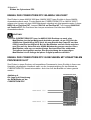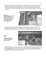
1
BREAKING THROUGH THE BARRIERS
POWERPC 604E BESCHLEUNIGERKARTE UND ULTRAWIDE SCSI CONTROLLER
FÜR AMIGA 3000(T) UND AMIGA 4000(T)
POWERPC 604E ACCELERATOR BOARD AND ULTRA WIDE SCSI CONTROLLER
FOR AMIGA 3000(T) AND AMIGA 4000(T)
ANWENDERHANDBUCH
USERS MANUAL PAGES 30-59
1. Auflage August 1997
Copyright 1996/1997
phase 5 digital products
In der Au 27
61440 Oberursel
Konzeptionelles Design:
Hardware-Design:
Software:
Dokumentation:
Best boy on set
Best girl on set
Satz & Layout:
Gerald Carda, Wolf Dietrich
Gerald Carda, Christian Keller, Li Zhang
Ralph Schmidt, Frank Mariak, André Osterhues,
Frank Gerberding
Uwe Trebbien, Michael Sistig
Thomas Knäbel
Brita
Michael Sistig
Warenzeichen: Workbench™, Intuition™, Amiga™, AmigaDOS™ sind eingetragene
Warenzeichen des jeweiligen Besitzers. Verwendete Produktnamen sind Gebrauchsmuster
und/oder Warenzeichen der jeweiligen Hersteller.
Text, Abbildungen, Programme und Hardware wurden mit größter Sorgfalt erarbeitet. Alle
Rechte sowie Änderungen in Technik und Lieferumfang vorbehalten. Die phase 5 digital
products kann jedoch für eventuell verbliebene fehlerhafte Angaben und deren Folgen weder
eine juristische Verantwortung noch irgendeine Haftung übernehmen. Die vorliegende
Publikation ist urheberrechtlich geschützt. Alle Rechte vorbehalten. Kein Teil dieses Buches
darf ohne schriftliche Genehmigung der phase 5 digital products in irgendeiner Form durch
Fotokopie, Mikrofilm, Text-Datei oder andere Verfahren reproduziert oder in eine für
Maschinen, insbesondere Datenverarbeitungsanlagen, verwendbare Sprache übertragen
werden. Eine Übersetzung dieses Handbuches in andere Sprachen, insbesondere ins
Englische oder Französische, bedarf ebenfalls der schriftlichen Genehmigung der phase 5
digital products.
1
INHALT
Einleitung
Einleitung
2
Lieferumfang
2
Systemvoraussetzung
3
Bevor Sie mit dem Einbau beginnen
3
Kapitel 1
Über die CYBERSTORM PPC
Das Konzept der CYBERSTORM PPC
4
Besonderheiten der CYBERSTORM PPC
5
Anwendungen für die CYBERSTORM PPC
6
Software für PowerUP®-Beschleuniger
7
Kapitel 2
Einbau
Einbau im AMIGA 4000
8
Installation der CYBERSTORM PPC
8
Einbau im Amiga 4000T
11
Einbau im Amiga 3000/3000(T)
12
Einbau in kompatiblen Rechnern
12
Kapitel 3
Speicheraufrüstung
Speicheraufrüstung
13
Einsetzen von SIMM-Modulen
14
Softwareinstallation
14
Kapitel 4
Der Ultra-WIDE-SCSI Controller
Der Ultra-WIDE-SCSI Controller
15
Anschluß bereits formatierter SCSI-Platten
15
Anschluß externer SCSI-Geräte
16
SCSI Terminierung
17
SCSI Terminierung (Beispiele)
18
Einstellen der SCSI-ID
22
Die SCSI-Software
23
Kapitel 5
Fehlersuche
Fehlersuche
24
Generelles zur Fehlersuche
25
Kapitel 6
Garantie
Garantiebestimmungen
26
Technische Beratung und Service
27
Garantieabwickung, Rücksendungen
27
2 CYBERSTORM PPC
Einleitung
EINLEITUNG
An dieser Stelle möchten wir uns zuerst bei Ihnen bedanken, daß Sie sich für unser Produkt
entschieden haben. Sie haben mit der CYBERSTORM PPC Beschleunigerkarte für den
Amiga ein hochqualitatives und ausgereiftes Produkt erworben, das nicht nur in
umfangreichen Versuchsserien vor seiner Markteinführung getestet und erprobt wurde,
sondern in dem sich auch langjährige Erfahrungen in der Entwicklung von Peripherie, im
speziellen von Planung von Zusatzerweiterungen, für den Amiga widerspiegeln. Der hohe
Aufwand, der bei der Entwicklung und Feinabstimmung dieser PowerPC Beschleunigerkarte
betrieben wurde, ist auch Maßstab bei der Produktion der Geräte sowie der Entwicklung der
Software gewesen. Dieser Aufwand gewährleistet daß die CYBERSTORM PPC höchsten
Ansprüchen an Qualität, Sicherheit, Kompatibilität und Leistung gerecht wird. Wir hoffen, daß
Sie mit diesem Produkt lange Freude haben werden. Wir möchten Sie an dieser Stelle bitten,
die diesem Produkt beigefügte Registrierungskarte ausgefüllt an uns einzusenden. Zum
einen können wir Sie so über mögliche zukünftige Erweiterungen und Updates der
CYBERSTORM PPC wie auch andere Entwicklungen für den Amiga informieren, zum
anderen helfen Sie uns mit Ihrer Meinung, auch in Zukunft die Produkte für den Amiga zu
entwickeln und auf den Markt zu bringen, die Sie sich als Anwender wünschen - Ihre
Meinung über die Leistung in der Praxis ist uns wichtig.
phase 5 digital products, im Sommer 1997
LIEFERUMFANG
Bitte überprüfen Sie bei Erhalt Ihrer CYBERSTORM PPC die Vollständigkeit der Lieferung.
Die Packung muß enthalten:
u Die CYBERSTORM PPC Turbokarte
u Zwei Installationsdisketten (PowerUp®-SCSI Disk und PowerUp®-System Disk)
u Die PowerUp® CD-ROM
u Dieses Handbuch
Sollte eines dieser Teile nicht enthalten sein, so wenden Sie sich bitte an Ihren Fachhändler.
3
SYSTEMVORAUSSETZUNG
Benötigte Konfiguration:
u Amiga 3000(T)/Amiga 4000(T) oder Rechner mit kompatiblem Prozessorslot
u mindestens 8 MByte auf der CYBERSTORM PPC installiertes Fast-RAM
u Festplatte
u Kickstart 3.x
Empfohlene Konfiguration:
u Amiga 3000(T)/Amiga 4000(T) oder Rechner mit kompatiblem Prozessorslot
u 16 MByte oder mehr auf der CYBERSTORM PPC installiertes Fast-RAM
u CD ROM Laufwerk, Festplatte, Kickstart 3.1
u Grafikkarte "CyberVision PPC" (erhältlich ab Quartal 4/1997)
BEVOR SIE MIT DEM EINBAU BEGINNEN
Bevor Sie mit dem Einbau der CYBERSTORM PPC beginnen, sollten Sie zuerst folgende
Punkte beachten:
1. Die CYBERSTORM PPC benötigt für eine korrekte Funktion spezielle 68k- und
PowerPC-spezifische Software. Diese Software muß vor dem Einbau der
CYBERSTORM PPC installiert werden. Siehe hierzu auch den Absatz
"Softwareinstallation".
2. Wenn Sie die CYBERSTORM PPC in einen AMIGA 3000/3000T einbauen wollen,
dann lesen Sie bitte zuerst den Absatz "Einbau im AMIGA 3000/3000T", um die
entsprechenden notwendigen Jumperkonfigurationen auf der Mutterplatine des
AMIGA 3000/3000T vornehmen zu können.
3. Um die volle Funktionalität der CYBERSTORM PPC zu gewährleisten, muß das
Kickstart-ROM Version 3.x installiert sein.
4. Um Ihre CYBERSTORM PPC mit den für den Betrieb notwendigen
Speichermodulen (SIMMs) aufzurüsten, lesen Sie bitte zuerst Kapitel 3, da der
Einbau der SIMMs vor dem Einbau der CYBERSTORM PPC in den Rechner
einfacher vorzunehmen ist.
4 Kapitel 1
Über die CYBERSTORM PPC
KAPITEL 1: ÜBER DIE CYBERSTORM PPC
DAS KONZEPT DER CYBERSTORM PPC
Die CYBERSTORM PPC Beschleunigerkarte ist - als erstes verfügbares Produkt der
PowerUP®-Produktlinie - ein hoch komplexes 2-Prozessor-Design, in dem zwei
unterschiedliche Prozessoren, ein PowerPC-Prozessor und ein 68k-Prozessor, parallel
betrieben werden. Da es sich um echtes Multiprocessing handelt, haben beide Prozessoren
vollen Zugriff auf den gesamten Adressraum des Rechners. Über eine umfangreiche
Softwarelösung wird der PowerPC-Prozessor so in das aktuelle Amiga-Betriebssystem
integriert, daß Multitasking auf beiden Prozessoren möglich ist, wobei
Anwendungsprogramme aus Tasks unter 68k- und PowerPC- Prozessor bestehen können.
Ziel der PowerUP®-Lösung ist, dem aktiven Anwender heute eine Möglichkeit zu geben, sein
bestehendes System bei vollständiger Kompatibilität zur vorhandenen Hardware und
Software mit einem neuen, um mehrere Größenordnungen leistungsstärkeren Prozessor
aufzurüsten. Hierzu haben wir die aufwendige 2-Prozessor-Lösung realisiert, in der der
Anwender sogar seinen - in vielen Fällen auf einer Prozessorkarte bereits vorhandenen - 68kProzessor und seine Software weiterverwenden kann. Auf diese Art und Weise kann - mit
entsprechend angepasster Software - die hohe Leistung des PowerPC-Prozessors nutzbar
gemacht werden, ohne daß ein kompletter Systemumstieg - inklusive Neukauf aller Hardware
und Software - nötig ist.
Software, die auf den neuen Prozessor angepasst wird, kann mit erheblichen
Leistungssteigerungen gegenüber den bislang schnellsten Lösungen auf dem Amiga
begeistern. Durch die Integration der PPC-Prozessoren in das Amiga-System mit einer
leistungsstarken Library können Software-Entwickler dabei Programme teilweise bzw. Schritt
für Schritt auf den PowerPC-Prozessor portieren - ein Lösungsweg, den viele aktuell an
PowerUP®-Versionen ihrer Software arbeitende Entwickler zu schätzen wissen. Langfristig
können auch vollständig auf dem PowerPC-Prozessor laufende Programme oder auch
Betriebssystemumsetzungen realisiert werden.
Mit diesen Funktionen stellt die CYBERSTORM PPC - wie auch die anderen PowerUP®Produkte - mehr als eine aktuelle Aufrüstungslösung für den Amiga dar. Sie kann vielmehr
auch als Entwicklungsplattform für zukünftige Generationen von Software und neue
Betriebssystemlösungen verwendet werden. Unter anderem werden die PowerUP®-Produkte
als Basis zur Entwicklung neuer Software- und Betriebssystemlösungen für zukünftige
Entwicklungen von phase 5 digital products eingesetzt werden, mit besonderem Fokus auf
Entwicklungen im Zuge des A\BOX-Projekts. Mit der Summe ihrer Eigenschaften stellt die
PowerUp®-Produktlinie die State-of-the-Art-Lösung unter den Prozessoraufrüstungen für alle
die Anwender dar, die allerhöchste Leistung für die anspruchsvollen Anwendungen von heute
und morgen erwarten, und wird von phase 5 digital products ausgebaut und intensiv gepflegt
wie auch von jenen Herstellern unterstützt werden, die sich weiterhin dem Amiga und seiner
Anwenderschaft verpflichtet fühlen.
5
WELCHE BESONDERHEITEN BIETET DIE CYBERSTORM PPC?
Neben vielen Details sind es vor allem die folgenden wesentlichen Merkmale, die die
CYBERSTORM PPC zu einer Hochleistungslösung machen:
Sehr hoher Speicherdurchsatz für PowerPC- und 68k-Prozessor:
Mit seinem sehr schnellen Speicherdurchsatz (bis zu 68MB/s unter 68060 und bis etwa
160MB/s unter PPC604e) ist die CYBERSTORM PPC für Anwendungen, die mit großen
Datenmengen operieren, sehr gut geeignet. Die CYBERSTORM PPC erreicht bereits unter
dem 68060-Prozessor durch ca. 50% schnelleren Speicher als die frühere CYBERSTORM
MKII eine in der Praxis bis zu 25% höhere Leistung (gemessen mit Lightwave 4.0Testberechnung). Für den PowerPC gibt es leider keine Vergleichswerte zu
Vorgängermodellen; allerdings sind die Speicherbandbreiten der PowerPC-Seite im
Vergleich zu vielen herkömmlichen PC-Systemen sehr hoch. Aufgrund dieses hohen
Durchsatzes im Hauptspeicher kann auch auf einen 2nd-Level-Cache verzichtet werden.
Schneller PowerPC-Bustakt:
Die CYBERSTORM PPC-Modelle werden mit einem 1:3-Verhältnis des PowerPCProzessor/Bustaktes ausgeliefert; die 200MHz-604e-Version arbeitet mit einem Bustakt von
66 MHz. Auch dies trägt zur hohen Performance der CYBERSTORM PPC im PowerPCBetrieb bei.
Schneller Wide Ultra SCSI Controller on board:
Der serienmäßig integrierte Controller nach dem Wide Fast-20 (Ultra)-Standard bietet
gewaltige Leistungsreserven mit modernen Massenspeichern, speziell natürlich den
modernen Festplatten der Desktop-Klasse. Damit werden Anwendungen, die auf hohen
Datendurchsatz angewiesen sind, erheblich beschleunigt. Der SCSI-Controller basiert auf
einem Symbios 53C770 SCSI Script Processor und arbeitet als DMA-Busmaster. Als
Anschluß steht eine 68poliger Wide Ultra SCSI-Connector auf der CYBERSTORM PPC zur
Verfügung.
Umfangreiche PPC-Library:
Die mitgelieferte PPC-Library stellt eine umfangreiche Funktionalität zur Einbindung des
PowerPC-Prozessors in das Amiga-Multitasking-System bereit. Dadurch ist der transparente
und parallele Betrieb bei der Prozessoren und die Erstellung und der Betrieb von Software,
die die Leistung beider CPUs nutzt, auf komfortable Weise möglich. Ein neuartiges MessageSystem erlaubt es Softwareentwicklern hierbei, zukunftsorientiert und modular strukturiert zu
programmieren.
Schneller Erweiterungsteckplatz
Ein schneller Erweiterungssteckplatz, ausgeführt auf einem hochwertigen Steckverbinder, ist
für den Anschluß von Erweiterungen vorgesehen. Für diesen Steckplatz wird Ende 1997 eine
6 Kapitel 1
Über die CYBERSTORM PPC
Hochleistungs-Grafikkarte auf Basis des Permedia2 3D-Grafikprozessors verfügbar werden.
Diese Grafikkarte wird die Geschwindigkeit aller Softwareanwendungen, die stark von der
Geschwindigkeit der Grafikausgabe abhängen - hierbei im ganz besonderen natürlich 3DAnwendungen - nocheinmal erheblich steigern und höchste Auflösungen bieten.
Sonstige Features:
– Einsteckkarte für Amiga 3000(T), 4000(T) und Rechner mit kompatiblem CPU-Slot
– Dual-Processor-System mit einem PowerPC 604e-Prozessor mit 150, 180 oder 200
MHz
– Steckplatz für einen (zum Betrieb notwendigen) 68k-Companion-CPU Typ 68040-25
oder -40 oder 68060-50
– Beide Prozessoren teilen sich dynamisch (d.h. nach Bedarf) den Buszugriff in den
gesamten verfügbaren Addressraum
– Aufrüstbar mit bis zu 128 MByte schnellem, 64-bit breitem Fast RAM, voll
autoconfigurierend
– Startupsoftware im Flash-ROM mit Upgrademöglichkeit per Softwareupdate
– Automatische, jumperlose Konfiguration
– Umfangreiches Softwarepaket mit PPC-Library, CyberGraphX V3-Treibersoftware mit
PPC-unterstütztem MPEG-Libraries und PPC-unterstützte CyberGL-3D-Library
– Aufwendige Verarbeitung unter Verwendung hochwertiger Komponenten, hergestellt in
Deutschland
FÜR WELCHE ANWENDUNGEN IST DIE CYBERSTORM PPC
BESONDERS GEEIGNET?
Grundsätzlich kann die CYBERSTORM PPC für alle Arten von Anwendungen verwendet
werden. Sinnvollerweise werden solche Anwendungen in den Vordergrund rücken, die hohe
Rechenleistung benötigen - also speziell die sogenannten Multimedia-Anwendungen, alle
Arten von Grafik- oder 3D-Anwendungen, Soundbearbeitung, Animation oder auch Spiele.
Gerade in diesen Bereichen sind viele Entwicklungen von Softwareherstellern in Arbeit. Aber
auch für Eigenentwicklungen oder z.B. wissenschaftliche Anwendungen ist die
CYBERSTORM PPC durch ihre hohe Rechenleistung besonders geeignet.
Anwendungen, die wesentlich von der Betriebssystemgeschwindigkeit abhängig sind, wie
z.B. User-Interface-Programme, Tools und Utilities, Textverarbeitungen o.ä. profitieren auf
der CYBERSTORM PPC initial vor allem von der höheren Geschwindigkeit des Speichers
und der damit verbundenen höheren Leistung des 68k-Prozessors. Aber auch bei solchen
7
Programmen ist die Nutzung der hohen PowerPC-Leistung für bestimmte Funktionen, wie
z.B. Datenkompression oder -dekompression, Font-Engines oder Postscript-Anwendungen
oder im allgemeinen die Einbindung von multimedialen Funktionen in solche Programme
sinnvoll und möglich - um nur einige mögliche Anwendungen aufzuzeigen.
WELCHE SOFTWARE IST FÜR POWERUP®-BESCHLEUNIGER
VERFÜGBAR?
Um die Verfügbarkeit von leistungsstarker Software zu unterstützen, hat phase 5 weltweit
Amiga-Software-Entwickler mit Developer-Systemen und Entwicklersupport unterstützt.
Einige Resultate in Form erster Software-Produkte sind bereits mit der Auslieferung der
ersten CYBERSTORM PPC-Karten verfügbar. Weitere wesentliche Entwicklungen sind in
der nahen Zukunft zu erwarten, da weitere Entwickler mit den Serienversionen der
CYBERSTORM PPC erstmalig mit der Entwicklung beginnen können, und die bereits an
PowerUP®-Software arbeitenden Entwickler nunmehr Serienprodukte zur Verfügung haben,
die die volle Leistung des PowerUP®-Konzepts entfalten können. Hierzu gehört auch die
aktuelle Release-Version der PPC-Library mit umfangreicher Funktionalität, die eine schnelle
Entwicklung einer neuen und leistungsstarken Software-Generation ermöglicht.
Mit den PowerUP® Produkten, der dazugehörigen Software-Entwicklung und unserem
Developer Support Programm wollen wir aber nicht nur aktuelle Produkte bieten, die die
Nutzbarkeit des Amiga in anspruchsvollen Anwendungen erweitern, sondern auch Pfade in
die Zukunft aufzeigen. Aus diesem Grund wird auch die Entwicklung alternativer
Betriebssysteme wie z.B. Linux, die voll unter der PowerPC-Seite laufen können, gefördert.
Durch die mitgelieferte Demo-Softwareware und Entwicklungstools (GNU C-Compiler,
Beispiele, Tools etc.) eignet sich das System damit auch weiterhin hervorragend für alle
Anwender, die selbst programmieren oder auch größere Softwareprojekte beginnen wollen.
Wir hoffen, damit die Nutzbarkeit des Amiga als universellen Kreativ-Computer weiter zu
unterstützen.
Auf der mitgelieferten CD finden Sie unter anderem Informationen über und/oder
Demoversionen von bereits verfügbaren PowerUP®-Produkten bzw. über in der
Fertigstellung, Vorbereitung oder Planung befindliche PowerUP®-Software. Aktuelle
Informationen sind ab Herbst 97 auf gesonderten Informationseiten in unseren InternetSeiten (www.phase5.de) verfügbar.
8 Kapitel 2
Einbau der Cyberstorm PPC
KAPITEL 2: EINBAU DER CYBERSTORM PPC
ACHTUNG!
Lesen Sie bitte vor der Installation der CYBERSTORM PPC dieses Handbuch
unbedingt durch, da bei Nichtbeachtung der Anleitung die Karte oder der
Rechner zu Schaden kommen kann. Desweiteren muß die Software vor dem
Einbau der CYBERSTORM PPC installiert werden. Bitte beachten Sie auf jeden
Fall auch die Garantieeinschränkungen (Kapitel 6) in Hinblick auf
unsachgemäßen Einbau.
Wenn Sie im System, in dem die CYBERSTORM PPC eingebaut werden soll, Festplatten
installiert haben, auf denen sich nicht gesicherte Daten befinden, raten wir dringend, VOR
dem Einbau der CYBERSTORM PPC ein Sicherungs-Backup der Festplatte(n) zu erstellen.
Jede Neuinstallation von Hardware-Zubehör birgt das - wenn auch noch so geringe - Risiko
einer Beschädigung empfindlicher Komponenten oder Fehlfunktionen aufgrund
unsachgemäßen Einbaus oder Vorgehens in sich; als Folge einer solchen Beschädigung
oder Fehlfunktion können Datenverluste auf bestehenden Festplatten durch Fehlfunktionen
bei der folgenden Inbetriebnahme auftreten. Sollte ggfs. ein Backup auf Diskette wegen
großer Datenmenge zu langwierig erscheinen, so fragen Sie Ihren Fachhändler, ob er für Sie
die Sicherung (z.B. auf einen Streamer) und Neuinstallation vornehmen kann, oder ob Sie
einen Streamer, evtl. gegen eine geringe Gebühr, ausleihen können. Wir weisen
ausdrücklich darauf hin, daß wir keinerlei Gewährleistung für Datenverluste übernehmen, die
evtl. im Falle einer Fehlfunktion des Systems in Folge des Einbaus der CYBERSTORM PPC
entstehen.
EINBAU DER CYBERSTORM PPC IM AMIGA 4000
Die CYBERSTORM PPC wird in den Prozessorsteckplatz des Amiga 4000 eingesetzt.
Dieser befindet sich zwischen der Slot-Platine und dem vorderen Laufwerksschacht. Die
Installation der Karte ist nicht sehr schwierig. Falls Sie jedoch keine Erfahrung beim Einbau
von Erweiterungskarten haben, Ihnen nach dem Durchlesen der Anleitung noch einiges
unklar ist, oder wenn Sie es generell bevorzugen, kann auch Ihr Fachhändler, u.U. gegen
eine geringe Gebühr, die Installation vornehmen. Bitte beachten Sie, daß der Einbau in
jedem Fall unter Beachtung der gängigen Maßnahmen gegen Beschädigungen durch
statische Aufladungen vorgenommen werden muß.
INSTALLATION DER CYBERSTORM PPC
1. Schalten Sie Ihren Computer aus.
2. Lösen Sie alle Kabel vom Rechner (Netz, Monitor, Maus, Tastatur, sonstige
Schnittstellen).
3. Lösen Sie die zwei Schrauben die den Gehäusedeckel halten. Diese befinden sich auf der
Rückseite links und rechts oben.
4. Entfernen Sie vorsichtig den Gehäusedeckel durch Hochklappen. Falls Ihnen dies nicht
gelingt, oder falls Sie weitere Informationen benötigen, lesen Sie bitte in Ihrem AmigaBenutzerhandbuch nach.
9
5. Um die Prozessorplatine auszutauschen ist es nötig, auch die Festplatte im hintern
Laufwerksschacht auszubauen. Zum Ausbau der Festplatte müssen nur die vier
Befestigungsschrauben gelöst und die Platte samt Halterung angehoben werden. Die
Anschlußkabel sind lang genug, um die Festplatte auf dem Netzteil abzulegen, ohne die
Kabel lösen zu müssen.
Abbildung 1.
Durch leichtes seitliches
Kippen läßt sich die CPUPlatine nach dem Lösen
vom Steckverbinder aus dem
Gehäuse nehmen.
6. Danach wird die Prozessorplatine wie in Abbildung 1 aus dem Rechner genommen. Falls
die Platine sehr fest sitzt, sollte darauf geachtet werden, daß auch alle vier Abstandshalter
lose sind. Die Platine kann nun durch leichtes Kippen aus dem Rechner herausgenommen
werden. Falls die Abstandshalter nicht in der Hauptplatine sondern auf der Pro-
Abbildung 2.
Auf diese Abstandshalter muß die
CYBERSTORM PPC
aufgesetzt werden.
zessorplatine sitzen, stecken Sie diese bitte in die dafür vorgesehenen Bohrungen auf der
Hauptplatine zurück, wie in Abbildung 2 zu sehen. Dies ist nötig, um einen möglichst
einfachen Einbau des CYBERSTORM PPC-Systems zu ermöglichen. Für Besitzer eines
AMIGA 4000/030 liegen zwei zusätzliche Abstandshalter bei.
10 Kapitel 2
Einbau der Cyberstorm PPC
7. Vor Einbau der Trägerplatine müssen die zwei Clock-Jumper, die auf dem Mainboard
unter der CPU-Platine mit "INT" oder "I" und "EXT" oder "E" beschriftet sind (siehe
Abbildung 3), auf die richtige Position gesetzt werden. Für den Betrieb der CYBERSTORM
PPC müssen diese auf die Position "EXT" gesetzt werden. Je nachdem, ob Sie das
CYBERSTORM PPC in einem AMIGA 4000/030 oder AMIGA 4000/040 einbauen, sind
diese Jumper auf die Position "EXT" oder auf die Position "INT" gesetzt. Bitte beachten
Sie, daß ein Betrieb der CYBERSTORM PPC in der falschen Position nicht möglich ist,
und der Rechner bei einer solchen falschen Position nicht mehr bootet.
Abbildung 3.
Position der ClockJumper, die in jedem
Fall korrekt gesetzt
werden müssen.
Abbildung 4.
Einbau der
CYBERSTORM PPC.
Der Kreis markiert
die Position der
Bohrung, in dem der
Abstandshalter
einrasten muß.
8. Die Trägerplatine wird in den Rechner eingebaut, indem sie zuerst auf den
Abstandshaltern aufgesetzt und dann festgedrückt wird (siehe Abbildung 4). Dabei ist zu
beachten, daß die Platine sowohl von den Abstandshaltern gehalten wird, als auch
vollständig im Prozessorstecker sitzt.
11
9. Die Festplatte wird samt Halterung wieder in umgekehrter Reihenfolge eingebaut, in der
sie ausgebaut wurde.
10. Zuletzt schließen Sie das Gehäuse wieder, schrauben es zu, und verbinden alle Kabel
wieder wie zuvor mit dem Rechner. Damit ist der Einbau abgeschlossen.
Abbildung 5.
Die fertig installierte
CYBERSTORM PPC.
Hinweis
Nur wenn Sie über das Kickstart-ROM Version 3.x in Ihrem AMGIA verfügen, ist
die CYBERSTORM PPC sofort betriebsbereit, und stellt ihre Leistung direkt nach
dem Einschalten zur Verfügung
EINBAU DER CYBERSTORM PPC IM AMIGA 4000T
Zum Einbau in einem AMIGA 4000T lesen Sie bitte in Ihrem AMIGA-Anwenderhandbuch das
Kapitel "3.1 Interne Erweiterungsoptionen". Hier wird ausführlich der Einbau eines
Prozessorerweiterungsmoduls erklärt. Beachten Sie auch unbedingt das Kapitel "Jumper auf
der Hauptplatine des A4000T" in Ihrem AMIGA-Anwenderhandbuch, und stellenSie sicher
das die Jumper J100 und J104 auf der Position EXTERN bzw "E" stehen!
Hinweis
Wir empfehlen, auf jeden Fall die von uns mitgelieferten Abstandshalter zu
benutzen, da diese ein einwandfreien geraden Sitz des CYBERSTORM PPC im
AMIGA 4000T gewährleisten (einige AMIGA 4000T aus der Produktion von Amiga
Technologies wurden irrtümlich mit zu langen Abstandshaltern ausgeliefert).
12 Kapitel 2
Einbau der Cyberstorm PPC
EINBAU DER CYBERSTORM PPC IM AMIGA 3000/3000T
Zum Einbau in einem AMIGA 3000 bzw. AMIGA 3000T lesen Sie bitte in Ihrem AMIGAAnwenderhandbuch nach. Für den Betrieb der CYBERSTORM PPC im AMIGA 3000(T)
müssen drei Jumper auf dem A3000-Mainboard unbedingt wie folgt gesetzt werden: Jumper
BRDCLK auf Position EXT, Jumper CPUCLK auf Position INT, und Jumper QUADCLK
auf Position EXT. Die Positionen der Jumper entnehmen Sie bitte dem AMIGAAnwenderhandbuch.
ACHTUNG!
Die CYBERSTORM PPC kann im AMIGA 3000 Desktop nur nach einer
Modifikation des Amiga-Mainboards betrieben werden, da am CPU-Slot des
A3000 eine Signalleitung (INT2) fehlt, die zum Betrieb des PowerPC und des
SCSI-Controllers benötigt wird. Bei der Modifikation muß ein Draht zwischen
zwei Pins auf der Unterseite des A3000-Mainboards gezogen werden. Diese
Modifikation sollte nur von authorisierten Servicestellen oder erfahrenen
Technikern durchgeführt werden. Eine Beschreibung der notwendigen
Modifikation ist auf Anfrage bei phase 5 digital products erhältlich.
EINBAU DER CYBERSTORM PPC IN RECHNERN MIT KOMAPTIBLEM
PROZESSOR SLOT
Zum Einbau in einem Rechner mit kompatiblem Prozessorslot, lesen Sie bitte in Ihrem vom
Hersteller mitgelieferten Handbuch nach, um die Jumpereinstellung für den Betrieb der
CYBERSTORM PPC korrekt einzustellen. Auch hier muß der Bustakt auf extern gesetzt
werden.
Abbildung 6.
Die Lage und Orientierung
der RAM-Bänke auf der
CYBERSTORM PPC
RAM-Bank "0"
RAM-Bank "1"
13
KAPITEL 3
SPEICHERAUFRÜSTUNG
Die CYBERSTORM PPC zeichnet sich durch eine 64 Bit breite Speicheraufrüstungsoption
aus, die durch vier Standard SIMM Sockel realisiert wird, in denen die SIMM-Module
installiert werden. Um die Funktion der CYBERSTORM PPC zu gewährleisten müssen
mindestens 8 MByte Fast-RAM (2 Module a 4 MB) auf der CYBERSTORM PPC installiert
sein. Bedenken Sie auch, daß es schon heute Softwareapplikationen gibt, die eine höhere
Speicheraufrüstung zur korrekten Funktion benötigen. Aufgrund des 64 Bit breiten RAMDesigns der CYBERSTORM PPC gilt folgendes zu beachten:
Die Organisation der SIMM-Module erfolgt über die RAM-Bänke "0" und "1". (siehe hierzu
Abbildung 6). Dabei gilt, daß RAM-Bank "0" als erstes bestückt werden muß. Die Bestückung
der RAM-Bänke mit SIMM-Modulen muß hierbei, aufgrund des 64 Bit breiten Zugriffs,
zwingend paarweise erfolgen! Achten Sie auch darauf auf jeden Fall für die Bestückung der
RAM-Bänke identische SIMM-Module (gleicher Hersteller, gleiche Zugriffszeit, etc.) zu
verwenden.Das Einstellen und Erkennen des auf der CYBERSTORM PPC installiertem RAM
geschieht vollautomatisch. Für die Speicherbestückung der RAM-Bänke benötigen Sie
mindestens zwei identische 32-Bit SIMMs, die allgemein unter der Bezeichnung PS2-Modul
erhältlich sind. Die CYBERSTORM PPC akzeptiert SIMMs der Speichergröße 4MB, 8MB,
16MB, 32MB und erlaubt auch die paarweise Mischbestückung dieser SIMMs nach RAMBänken geordnet; es ist allerdings notwendig daß ALLE auf der CYBERSTORM PPC
installierten SIMMs die gleiche Geschwindigkeit haben.
BEISPIEL:
Sie können auf der RAM-Bank "0" zwei 8 MB große SIMMs installieren und auf
RAM-Bank "1" zwei 16 MB große SIMMS installieren und würden so einen
Gesamtspeicher von (2 x 8) + (2 x 16) = 48 MByte erhalten. Hierbei ist
grundsätzlich egal in welcher RAM-Bank das SIMM-Modul-Paar mit der größeren
Kapazität installiert wird.
ACHTUNG!
Erfolgt die Bestückung nicht paarweise oder nicht nach den RAM-Bänken
orientiert, wie oben beschrieben, so kann dies zur fehlerhaften RAM-Erkennung
des CYBERSTORM PPC-Systems und daraus resultierenden Fehlfunktionen
führen!
Die Organisation der SIMMs darf sowohl 32 Bit als auch 36 Bit betragen. Die 36-Bit SIMMs
werden in IBM-kompatiblen PCs verwendet, die die zusätzlichen 4 Bit als Paritätsbit
verwenden. Bei der CYBERSTORM PPC werden diese zusätzlichen Bits ignoriert. Für den
Betrieb in einer CYBERSTORM PPC werden SIMMs mit 70ns Geschwindigkeit oder
schneller benötigt.
Bitte beachten Sie, das es SIMM-Module verschiedenster Hersteller gibt, die die
aufgedruckte Geschwindigkeit nicht einhalten. Speziell SIMM-Module die z.B. den Aufdruck
LaserPrinter-Memory (oder ähnliche Fantasiebezeichnungen) tragen sind als Speicher für
Computersysteme ungeeignet. phase 5 digital products rät von einer Verwendung solcher
SIMM-Module prinzipiell ab.
14 Kapitel 3
Speicheraufrüstung
EINSETZEN VON SIMM-MODULEN
Legen Sie die CYBERSTORM PPC auf eine ebene, feste Unterlage. Beachten Sie, daß
empfindliche Oberflächen durch die Pins auf der Unterseite beim Einsetzen des
Speichermoduls zerkratzt werden könnten; wir empfehlen daher als Unterlage z.B. eine
Zeitschrift. Richten Sie die CYBERSTORM PPC jetzt so aus, daß die 68k CPU nach links
weist. Die Speicher-SIMMs haben auf einer Seite der Steckkontaktleiste eine Aussparung,
damit sie nicht verkehrt eingesetzt werden können. Diese Aussparung muß sich beim
Einsetzen auf der linken Seite befinden. Setzen Sie das SIMM in einem Winkel von etwa 40°
bündig in den Sockel ein; das Modul läßt sich so problemlos einsetzen. Dann drücken Sie mit
den Daumen auf beiden oberen Ecken das SIMM sanft nach unten, bis es hörbar einrastet.
Achten Sie darauf, daß die Metallhaken links und rechts bei den Fixierlöchern beide über die
Platine des SIMMs einrasten. Beachten Sie bei allen Arbeitsschritten, daß das SIMM keiner
starken mechanischen Belastung ausgesetzt werden darf.
SOFTWAREINSTALLATION
Die mitgelieferte "PowerUP® System Disk" umfaßt die notwendigen Libraries zum Betrieb
der 68k Companion- und der PowerPC CPU sowie einige Tools für den Betrieb der beiden
CPUs.
Hinweis
Die Installation der Software muß auf jeden Fall vor dem Einbau der
CYBERSTORM PPC in den Rechner erfolgen!
Die Installation der Software wird durch ein Installationsskript vorgenommen. Legen Sie die
mitgelieferte "PowerUP® System Disk" ein und öffnen Sie durch Doppelklicken mit der Maus
die Diskette. Sie sollten vor der endgültigen Installation die auf der Diskette vorhandene
"LiesMich"-Datei durch Doppelklicken aufrufen. In diesem Text sind die aktuellen
Informationen zur Software enthalten. Die Software wird dann durch Doppelklicken auf das
INSTALL Icon installiert. Die einzelnen Programme haben eine eigene Dokumentation in
Form von Readme-Dateien auf der Diskette.
15
KAPITEL 4
DER ULTRA WIDE-SCSI DMA CONTROLLER
Der SCSI-Controller der CYBERSTORM PPC arbeitet nach dem Wide Fast-20 (Ultra)Standard und bietet Übertragungsraten bis maximal 40 MB/s auf dem SCSI-Bus bei
Verwendung moderner ULTRA WIDE SCSI-Geräte. Damit werden Anwendungen, die auf
hohen Datendurchsatz angewiesen sind, erheblich beschleunigt. Der SCSI-Controller basiert
auf einem Symbios 53C770 SCSI Script Processor und arbeitet als DMA-Busmaster. Als
Anschluß steht eine 68poliger Wide Ultra SCSI-Connector auf der CYBERSTORM PPC zur
Verfügung.
Der ULTRA-WIDE-SCSI Controller der CYBERSTORM PPC kann seine volle Leistung am
besten erreichen, wenn nur ULTRA-WIDE-Geräte angeschlossen sind. Im folgenden wird
auch der Betrieb von Fast SCSI-Geräten an diesem Controller beschrieben, aber wir
empfehlen, Fast SCSI-Geräte an einem Fast SCSI-Controller weiter zu betreiben, sofern ein
solcher im System vorhanden ist. Der Anschluß von Fast SCSI-Geräten am ULTRA WIDEController kann die Datenübertragungsgeschwindigkeit am gesamten SCSI Bus auf die
Geschwindigkeit von Fast-SCSI einschränken.
ANSCHLUSS BEREITS RDB-FORMATIERTER SCSI-PLATTEN
Wenn Sie an dem CYBERSTORM PPC SCSI eine Festplatte (ggfs. auch ein anderes SCSIGerät) anschließen, das bereits vorher an einem SCSI-Controller im AMIGA betrieben und
mit dem RDB (Rigid Disk Block) gemäß Amiga-Standard formatiert wurde, so ist dieses
Gerät sofort betriebsbereit. Nach dem Starten des Rechners müssen die auf dieser Platte
vorhandenen Partitionen automatisch erkannt und ggfs. sogar von ihnen gebootet werden
können. Sollte dies nicht der Fall sein, so setzen Sie sich auf jeden Fall mit Ihrem
Fachhändler in Verbindung, bevor Sie weitere Maßnahmen ergreifen.
ACHTUNG!
Wenn Sie Festplatten anschließen wollen, die Sie bereits an einem anderen
Controller im Betrieb haben, und auf denen sich Daten befinden, raten wir
VOR
Ausbau aus dem alten System ein Sicherungs-Backup der
dringend,
Festplatte zu erstellen. Jeder Neuanschluß einer bereits betriebenen Festplatte
birgt das - wenn auch noch so geringe - Risiko eines Datenverlustes durch
Fehler bei Installation oder Inbetriebnahme in sich. Sollte ggfs. ein Backup auf
Diskette wegen großer Datenmenge zu langwierig erscheinen, so fragen Sie
Ihren Fachhändler, ob er für Sie die Sicherung (z.B. auf einen Streamer) und
Neuinstallation vornehmen kann, oder ob Sie einen Streamer, evtl. gegen eine
geringe Gebühr, ausleihen können. Wir weisen darauf hin, daß wir keinerlei
Gewährleistung für Datenverluste auf bereits vor dem Anschluß an dem
CYBERSTORM PPC SCSI benutzten Festplatten oder SCSI-Geräten übernehmen.
16 Kapitel 4
Der Ultra-WIDE-SCSI Controller
ANSCHLUSS UND BETRIEB INTERNER
UND EXTERNER SCSI-GERÄTE
Die CYBERSTORM PPC verfügt über einen nicht terminierten internen Wide Ultra-SCSIAnschluß in Form des standardisierten 68poligen HighDensity-Steckers. Über diesen
Anschluß werden mit den entsprechenden Kabeln und Adaptern alle Arten von internen und
externen SCSI-Geräten angeschlossen. Wesentlich ist dabei, daß der SCSI-Bus korrekt
terminiert wird, wie die weiter unten folgenden Beispiele aufzeigen, und daß die SCSI-ID der
Geräte ordnungsgemäß eingestellt ist, wie ebenso im folgenden erläutert wird. Die SCSIKabel und Adapter sind grundsätzlich über den Fachhandel zu beziehen; wir empfehlen, daß
Sie sich hierzu an den Fachhändler, über den Sie auch Ihre CYBERSTORM PPC bezogen
haben, wenden.
Interne ULTRA WIDE SCSI-Geräte werden grundsätzlich über interne 68polige
Flachbandkabel angeschlossen. Sollen FAST SCSI-Geräte angeschlossen werden, so wird
ein Adapter auf die 50poligen FAST SCSI-Kabel benötigt. Dieser Adapter muß in jedem Fall
die oberen acht Datenleitungen des WIDE SCSI-Busses aktiv terminieren; achten Sie daher
darauf, daß Sie den richtigen Adapter wählen.
Zum Anschluß externer SCSI-Geräte werden sogenannte Extern-Adapter verwendet, die es
in verschiedenen Formen gibt. Bei der Auswahl ist darauf zu achten, daß Sie die gewünschte
externe Schnittstelle wählen (je nachdem, ob Sie extern ULTRA WIDE SCSI-Geräte oder
FAST SCSI-Geräte anschließen wollen), und daß der Adapter - falls er einen Übergang von
ULTRA WIDE SCSI auf FAST SCSI bildet - eine entsprechende Terminierung der oberen
acht Datenleitungen des ULTRA WIDE SCSI-Busses beinhaltet.
Beim Betrieb der externen Geräte ist darauf zu achten, daß die externen Geräte immer vor
dem Rechner selbst eingeschaltet werden, und umgekehrt erst nach dem Ausschalten des
Rechners ausgeschaltet werden.
Hinweis
Zum Anschluß externer SCSI-Geräte sind nur hochwertige und abgeschirmte
Kabel zulässig, die den geltenden Normen (CE, FCC, o.ä.) entsprechen! Zum
Bezug solcher Kabel, die die entsprechenden Dämpfungseigenschaften bieten,
wenden Sie sich bitte an Ihren Fachhändler. Bitte beachten Sie auch, daß
externe SCSI-Geräte die geltenden Normen erfüllen müssen!
Abbildung 7.
CYBERSTORM PPC
Ultra-Wide-SCSI
Controller
Aktiv
terminiertes
SCSI-Gerät oder
Terminatorstecker
SCSISCSIGerät 1 Gerät 2
Aktiv
terminiertes SCSIEndgerät oder
Terminatorstecker
17
SCSI-BUS-TERMINIERUNG
Um eine einwandfreie Funktion des SCSI-Bussystems zu gewährleisten, muß der SCSI-Bus
elektrisch korrekt abgeschlossen (Fachausdruck: terminiert) werden. Sie können sich den
SCSI-Bus immer als ein einziges Kabel vorstellen, das an jedem Ende aktiv termimiert sein
muß. Die einzelnen Geräte - zu denen in diesem Fall auch der CYBERSTORM PPC SCSI
Controller zählt, der selbst über keine Terminierung verfügt - werden dann an diesem Kabel
direkt angeschlossen (wie in Abbildung 7 dargestellt). Hieraus folgt, daß die aktive
Terminierung nur auf dem ersten und letzten Gerät, welche an den beiden Enden des SCSIKabels angeschlossen sind, installiert sein darf, und der Anschluß an den CYBERSTORM
PPC SCSI Controller an einer beliebigen Stelle zwischen den beiden terminierten Busenden
Abbildung 8.
Eine korrekt
angeschlossene
Ultra-WIDE-SCSI
Festplatte am
CYBERSTORM PPC
Ultra-Wide-SCSI
Controller
Aktiv
terminierte
Ultra-Wide-SCSI
Festplatte
Anschluß des UltraWIDE-SCSI Controllers
auf der CYBERSTORM PPC
Aktiver
Terminator
erfolgen kann. Die Terminierung wird entweder mittels eines angeschlossenen SCSI-Geräts
(z.B. Festplatte mit aktiver Terminierung) oder eines aktiven Terminators vorgenommen
(wie beispielhaft in Abbildung 8 dargestellt). Einen Sonderfall bildet hierbei der Übergang von
WIDE-SCSI zu Standard SCSI: Hier müssen die Signalleitungen, die nur bei WIDE-SCSI
vorhanden sind, aktiv terminiert werden. Aus diesem Grund muß ein entsprechender Adapter
von WIDE- auf Fast-SCSI gewählt werden, der die acht zusätzlichen Signalleitungen des
WIDE-SCSI-Bus aktiv terminiert.
Auf älteren SCSI-Geräten sind teilweise passive Abschlußwiderstände installiert. Diese
passiven Abschlußwiderstände befinden sich im allgemeinen in der Nähe des SCSISteckers. Sie dürfen nicht zur Terminierung benutzt werden, da der SCSI-BUS des
CYBERSTORM PPC SCSI Controllers immer aktiv terminiert sein muß! Zur Deaktivierung
der Terminierung auf solchen SCSI-Geräten (je nach Gerät durch Entfernen der Widerstände
oder Einstellung über Steckbrücken oder Schalter) lesen Sie bitte in der Dokumentation des
betreffenden SCSI-Geräts nach. Bei externen Geräten (z.B. Scannern) oder auch externen
Laufwerken muß auf jeden Fall auch auf aktive Termination (z.B. mittels einem aktiven
Terminatorsteckers) geachtet werden.
18 Kapitel 4
Der Ultra-WIDE-SCSI Controller
ACHTUNG!
Die korrekte aktive Terminierung ist für einen fehlerfreien Betrieb des
Controllers und angeschlossener Geräte notwendig. Eine fehlerhafte bzw. nicht
aktive Terminierung führt zu Datenübertragungsfehlern, Nichterkennen von
SCSI-Geräten oder im schlimmsten Fall auch zu Datenverlusten auf
Speichermedien. Achten Sie unbedingt darauf, daß die Terminierung korrekt
durchgeführt ist und vermeiden Sie auf jeden Fall eine Mischung von passiver
und aktiver Termination!
SCSI TERMINIERUNG (BEISPIELE)
Betrieb eines internen WIDE SCSI Geräts
Die Terminierung des Geräts muß eingeschaltet sein und das Gerät muß am physikalischen
Ende des Kabels angeschlossen sein. Der Anschluß des CYBERSTORM PPC SCSI wird mit
einem der mittleren Abgriffe des WIDE SCSI Kabels verbunden. Am noch freien Ende des
Kabels wird ein aktiver Terminator angeschlossen.
CYBERSTORM PPC
Ultra-Wide-SCSI
Controller
Aktiv
terminiertes
Ultra-WIDE-SCSI
Gerät
Aktiver
Terminator
Betrieb eines internen Fast SCSI Geräts
Die Terminierung des Geräts muß eingeschaltet sein und das Gerät muß mittels eines
Adapters WIDE auf Fast SCSI am physikalischen Ende des Kabels angeschlossen sein. Der
Anschluß des CYBERSTORM PPC SCSI wird mit einem der mittleren Abgriffe des WIDE
SCSI Kabels verbunden. Am noch freien Ende des Kabels wird ein aktiver Terminator
angeschlossen.
CYBERSTORM PPC
Ultra-Wide-SCSI
Aktiv terminiertes
Controller
Fast-SCSI
Aktiver
Gerät mit
Terminator
Adapter von
Wide- auf FAST-SCSI
Betrieb mehrerer interner WIDE SCSI Geräte.
Der Anschluß des CYBERSTORM PPC SCSI wird mit einem der mittleren Abgriffe des
WIDE SCSI Kabels verbunden. An jedem physikalischen Ende des Kabels muß ein SCSI
Gerät mit aktivierter Terminierung angeschlossen sein. Weitere Geräte können mit
deaktivierter Terminierung an noch freien Abgriffen des Kabels angeschlossen werden.
19
CYBERSTORM PPC
Ultra-Wide-SCSI
Controller
Aktiv
terminiertes
UW-SCSI-Gerät oder
Terminatorstecker
UW-SCSI-Geräte
nicht terminiert
Aktiv
terminiertes UWSCSI-Endgerät oder
Terminatorstecker
Betrieb mehrerer interner Fast SCSI Geräte
Der Anschluß des CYBERSTORM PPC SCSI wird mit einem der mittleren Abgriffe des
WIDE SCSI Kabels verbunden. An einem Ende des WIDE SCSI Kabels wird ein aktiver
Terminator angeschlossen. Am anderen Ende des WIDE SCSI Kabels wird über einen
Adapter WIDE- auf Fast SCSI das Ende eines Fast SCSI Kabel angeschlossen. Eines der
Fast SCSI Geräte muß mit aktivierten Terminatoren am anderen Ende das Fast SCSI Kabels
angeschlossen werden. Weitere Fast SCSI Geräte können an freien Abgriffen des Fast SCSI
Kabels angeschlossen werden.
CYBERSTORM PPC
Ultra-Wide-SCSI
Controller
Aktiver
Adapter WIDETerminator
auf FAST-SCSI
Aktiv
terminiertes
Fast-SCSI-Gerät
Fast-SCSI-Geräte
nicht terminiert
Betrieb interner Fast SCSI und WIDE SCSI Geräte
Der Anschluß des CYBERSTORM PPC SCSI wird mit einem der mittleren Abgriffe des
WIDE SCSI Kabels verbunden. An einem Ende des WIDE SCSI Kabels wird ein WIDE SCSI
Gerät mit aktivierter Terminierung angeschlossen. Weitere WIDE SCSI Geräte können an
freien Abgriffen des WIDE SCSI Kabels angeschlossen werden. Am anderen Ende des
WIDE SCSI Kabels wird über einen Adapter WIDE- auf Fast-SCSI das Ende eines Fast SCSI
Kabel angeschlossen. Der verwendete Adapter muß die Möglichkeit bieten, nur die obere
Hälfte des WIDE SCSI Bus zu terminieren.
CYBERSTORM PPC
Ultra-Wide-SCSI
Aktiv terminiertes
Controller
UW-SCSI-Gerät oder
Adapter WIDETerminatorstecker
UW-SCSI-Geräte
auf FAST-SCSI
nicht terminiert
Aktiv terminiertes
FAST-SCSI Gerät
oder
Fast-SCSI-Geräte
Terminatorstecker
nicht terminiert
Ein Fast SCSI Gerät muß mit aktivierten Terminatoren am anderen Ende das Fast SCSI
Kabels angeschlossen werden. Weitere Fast SCSI Geräte können an freien Abgriffen
20 Kapitel 4
Der Ultra-WIDE-SCSI Controller
des Fast SCSI Kabels angeschlossen werden.
Betrieb externer Geräte ohne interne Geräte
Der Externadapter wird am physikalischen Ende des Kabels angeschlossen. Der Anschluß
des CYBERSTORM PPC SCSI wird mit einem der mittleren Abgriffe des WIDE SCSI Kabels
verbunden. Am noch freien Ende des Kabels wird ein aktiver Terminator angeschlossen.
CYBERSTORM PPC
Ultra-Wide-SCSI
Adapter zum
Controller
Anschluß
Aktiver
externer SCSITerminator
Geräte
Betrieb externer Geräte mit internen WIDE SCSI Geräten
Der Externadapter wird am physikalischen Ende des Kabels angeschlossen. Wenn keine
externen Geräte angeschlossen sind, muß auf den Externadapter ein aktiver Terminator
aufgesteckt werden. Der Anschluß des CYBERSTORM PPC SCSI wird mit einem der
mittleren Abgriffe des WIDE SCSI Kabels verbunden. Am noch freien Ende des Kabels wird
ein WIDE SCSI Gerät mit aktivierter Terminierung angeschlossen. Weitere WIDE SCSI
Geräte können mit deaktivierter Terminierung an noch freie Abgriffe des WIDE SCSI Kabels
anngeschlossen werden.
CYBERSTORM PPC
Ultra-Wide-SCSI
Aktiver Terminator
Controller
Aktiv
wenn keine
terminiertes
externen Geräte Adapter zum
UW-SCSIUW-SCSI Gerät
angeschlossen
Anschluß
Geräte
oder Terminator
sind
externer
nicht
SCSI-Geräte
terminiert
Betrieb externer Geräte mit internen Fast SCSI Geräten
Der Externadapter wird am physikalischen Ende des Kabels angeschlossen. Wenn keine
externen Geräte angeschlossen sind, muß auf den Externadapter ein aktiver Terminator
Adapter zum
Anschluß
CYBERSTORM PPC
externer
Ultra-Wide-SCSI
SCSI-Geräte Controller
Adapter WIDEauf FAST-SCSI
Aktiver
Terminator
wenn keine
externen Geräte
angeschlossen sind
Aktiv terminiertes
Fast-SCSI Gerät oder
Terminatorstecker
Fast-SCSI Geräte
nicht terminiert
21
aufgesteckt werden. Der Anschluß des CYBERSTORM PPC SCSI wird mit einem der
mittleren Abgriffe des WIDE SCSI Kabels verbunden. Am anderen Ende des WIDE SCSI
Kabels wird über einen Adapter WIDE- auf Fast SCSI das Ende eines Fast SCSI Kabel
angeschlossen. Der verwendete Adapter muß die Möglichkeit bieten, nur die obere Hälfte
des WIDE SCSI Bus zu terminieren. Ein Fast SCSI Gerät muß mit aktivierten Terminatoren
am anderen Ende des Fast SCSI Kabels angeschlossen werden. Weitere Fast SCSI Geräte
können an freien Abgriffen des Fast SCSI Kabels angeschlossen werden.
Betrieb externer Geräte mit internen Fast SCSI und WIDE SCSI Geräten
Der Externadapter wird am physikalischen Ende des Kabels angeschlossen. Wenn keine
externen Geräte angeschlossen sind, muß auf den Externadapter ein aktiver Terminator
aufgesteckt werden. Der Anschluß des CYBERSTORM PPC SCSI wird mit einem der
mittleren Abgriffe des WIDE SCSI Kabels verbunden. Am anderen Ende des WIDE SCSI
Kabels wird über einen Adapter WIDE- auf Fast SCSI das Ende eines Fast SCSI Kabel
angeschlossen. Der verwendete Adapter muß die Möglichkeit bieten, nur die obere Hälfte
des WIDE SCSI Bus zu terminieren. Die WIDE SCSI Geräte werden mit deaktivierten
Terminatoren an noch freien Abgriffen des WIDE SCSI Kabels angeschlossen. Ein Fast
SCSI Gerät muß mit aktivierten Terminatoren am anderen Ende das Fast SCSI Kabels
angeschlossen werden. Weitere Fast SCSI Geräte können an freien Abgriffen des Fast SCSI
Kabels angeschlossen werden.
Adapter zum
Anschluß
CYBERSTORM PPC
externer
Ultra-Wide-SCSI
SCSI-Geräte Controller
Aktiver
Terminator
wenn keine
externen Geräte
angeschlossen sind
Aktiv terminiertes
Fast-SCSI Gerät oder
Terminatorstecker
UW-SCSI-Geräte
nicht terminiert
Fast-SCSI Geräte
nicht terminiert
Adapter WIDEauf FAST-SCSI
22 Kapitel 4
Der Ultra-WIDE-SCSI Controller
EINSTELLEN DER SCSI-ID DER ANGESCHLOSSENEN GERÄTE
Zur Unterscheidung verschiedener Geräte, die am SCSI-Bus angeschlossen sind, haben
SCSI-Geräte eine sogenannte SCSI-ID, die einen Wert von 0-7 für FAST SCSI-Geräte und
von 0 bis 15 für WIDE SCSI-Geräte annehmen kann. Der integrierte SCSI Controller auf dem
CYBERSTORM PPC SCSI hat selbst die ID 7. Daraus folgt, daß an einem CYBERSTORM
PPC SCSI bis zu 7 FAST SCSI Geräte mit den IDs 0-6 oder bis zu 15 WIDE SCSI Geräte mit
den IDs 0-6 und 8-15 angeschlossen werden können.
Sollen mehrere SCSI-Geräte am CYBERSTORM PPC SCSI angeschlossen werden, so
müssen bei diesen Geräten die SCSI-ID so eingestellt werden, daß kein Gerät die gleiche ID
hat. Die SCSI-ID ist bei externen SCSI-Geräten im allgemeinen mit einem kleinen Schalter
vom Anwender einstellbar. Bitte konsultieren Sie hierzu die Dokumentation des betreffenden
SCSI-Geräts.
ACHTUNG!
Werden zwei Geräte mit gleicher SCSI-ID am CYBERSTORM PPC SCSI
angeschlossen, so kann dies zur Beschädigung eines der SCSI-Geräte führen. In
jedem Fall wird nur eines dieser Geräte von der CYBERSTORM PPC SCSISoftware erkannt. Umgekehrt ist es, wenn nach Anschließen z.B. einer neuen
Festplatte diese von der CYBERSTORM PPC SCSI-Software nicht erkannt wird,
ein Hinweis darauf, daß möglicherweise an dieser Platte eine SCSI-ID eingestellt
ist, die schon einem anderen Gerät vergeben ist. Das gleiche gilt natürlich, wenn
die neue Platte erscheint, dafür aber auf einmal ein bereits vorher
angeschlossenes Gerät nicht mehr angesprochen werden kann. Um auf jeden
Fall den Betrieb von zwei SCSI-Geräten mit gleicher ID zu vermeiden, sollten Sie
vor Anschluß eines neuen SCSI-Geräts mit der CYBERSTORM PPC SCSISoftware (z.B. dem Programm UnitControl) überprüfen, welche SCSI-IDs schon
vergeben sind.
Hinweis
Die Reihenfolge, in der die SCSI-IDs vergeben werden, ist im Prinzip
vollkommen frei wählbar, d.h., es müssen weder SCSI-IDs in Folge vergeben
werden, noch hängt die wählbare SCSI-ID von der Position des Geräts in z.B.
einer Reihe angeschlossener Platten ab. Dennoch ist es empfehlenswert dem
ersten angeschlossenen Gerät die ID 0 zu vergeben, und später
angeschlossenen Geräten die folgenden IDs in aufsteigender Reihenfolge
zuzuweisen, da dies die System-Startzeit deutlich verkürzen kann. Ausnahme
hierzu bildet die ID Vergabe für WIDE SCSI Geräte im Mischbetrieb. Um die IDs
für FAST SCSI Geräte, die ja nur IDs von 0-6 belegen können, freizuhalten,
sollten WIDE SCSI Geräte in diesem Sonderfall auf IDs 8-15 eingestellt werden.
23
ACHTUNG!
Bei einigen Festplatten kann es vorkommen, daß sie auf der SCSI-ID 0 nicht
korrekt funktionieren. In diesem speziellen Fall ändern Sie bitte die SCSI-ID auf
eine beliebig andere ID.
DIE SCSI-SOFTWARE
Dieser Absatz beschreibt die Installation der SCSI-Software die sich auf der mitgelieferten
"PowerUP® SCSI-Disk" befindet.
Auf der "PowerUP® SCSI-Disk" befindet sich ein Installationsprogramm, mit dem die
benötigte Software installiert wird. Die Installation teilt sich in den Bereich reine Installation
und Konfiguration des mitgelieferten CD ROM Filesystems.
Zur Installation der Software legen Sie die Diskette ein und führen das auf der Diskette
enthaltene Installationsprogramm aus.
Die Dokumentation der Software ist auf der Diskette und wird bei der Installation automatisch
mitinstalliert. Nach der Installation ist die Dokumentation zur Software als README-Datei
verfügbar.
Hinweis
Bei Programmen, die die Angabe des SCSI-Treibers benötigen müssen Sie als
Device-Namen cybppc.device angeben. Bei machen Programmen kann es nötig
sein, daß der Device-Name in Anführungszeichen eingeschlossen wird.
24 Kapitel 5
Fehlersuche
KAPITEL 5
FEHLERSUCHE
Fehler: Der Rechner läßt sich nicht mehr starten
Überprüfen Sie, ob das Netzkabel sicheren Kontakt hat. Ist dies der Fall, so wenden Sie sich
bitte an Ihren Fachhändler.
Fehler: Autoconfig-Fehler
Erscheint nach dem Starten des Rechners bzw. einem Reset ein roter Bildschirm mit dem
Titel "Expansion Board Diagnostic", so wenden Sie sich bitte an Ihren Fachhändler.
Fehler: Ein SCSI-Gerät wird nicht erkannt
Überprüfen Sie, ob das Gerät an die interne Stromversorgung angeschlossen ist.
Bei externen Geräten: Überprüfen Sie, ob das Netzkabel des externen Geräts korrekt
angeschlossen ist, und ob das Gerät eingeschaltet ist.
Überprüfen Sie die SCSI-IDs der angeschlossenen Geräte.
Überprüfen Sie den Anschluß des SCSI-Kabels am CYBERSTORM PPC SCSI Controller
und am SCSI-Gerät.
Überprüfen Sie bei externen Geräten den korrekten Sitz der externen SCSI-Kabel.
Überprüfen Sie die korrekte SCSI-Bus-Terminierung.
Tauschen Sie ggfs. das Kabel oder schließen Sie (bei internen Geräten) das SCSI-Gerät an
einem anderen Stecker des Kabels an, um eventuelle Fehler des Kabels zu finden.
Fehler: Die Partitionen einer vorher bereits formatierten Platte werden nicht erkannt
Zuerst sollten Sie anhand des mit dem CYBERSTORM PPC gelieferten Programms
UnitControl überprüfen, ob die entsprechende Festplatte physikalisch erkannt wird. Ist dies
nicht der Fall, so führen Sie die Maßnahmen der vorhergehenden Fehlerbeschreibung durch.
Wird die Platte erkannt, so überprüfen Sie, ob der vorher verwendete Controller RDBkompatibel war; bitte beachten Sie auch die Schritt-für-Schritt-Anleitung zum Anmelden einer
Festplatte. Können Sie mit der dort beschriebenen Vorgehensweise die Platte nicht
anmelden, so wenden Sie sich bitte an Ihren Fachhändler, bevor Sie weitere Maßnahmen
ergreifen.
Fehler: Beim Betrieb einer Festplatte treten Übertragungsfehler auf
Überprüfen Sie die korrekte SCSI-Bus-Terminierung bzw. Terminierung der einzelnen
angeschlossenen Geräte.
Überprüfen Sie die SCSI-IDs der angeschlossenen Geräte.
Überprüfen Sie den korrekten Anschluß der SCSI-Kabel. Tauschen Sie ggfs. das Kabel, um
mögliche Kabelstörungen festzustellen.
25
Eine weitere Ursache für Übertragungsfehler kann es sein, wenn ein SCSI-Gerät, speziell bei
externem Betrieb mit langen Kabeln, im Synchron-Modus mit hohen Übertragungsraten
betrieben wird. Probieren Sie in diesem Fall, die Übertragungsrate mittels UnitControl
herabzusetzen.
Problem: Ein SCSI-Gerät arbeitet langsamer als zu erwarten
Überprüfen Sie die korrekten Einstellungen der synchronen Übertragung und der Mask- und
MaxTransfer-Werte der betroffenen Partitionen. Dazu können Sie das Programm CheckMask
verwenden.
Überprüfen Sie bei unter AMIGA-DOS betriebenen Partitionen, ob diese mit dem
FastFileSystem (FFS) betrieben werden. Die Einstellung FastFileSystem Internationaler
Modus (FFS Int) kann zu Leistungseinbußen führen; ebenso führt die AMIGA-DOSFormatierung mit Verzeichnis-Cache oft zu einer deutlichen Verminderung der
Übertragungsrate.
Überprüfen Sie ggfs., ob die Festplatte sehr voll und die Dateien über viele Spuren verteilt
sind. In einem solchen Fall kann es sinnvoll sein, die Festplatte zu optimieren; hierzu gibt es
spezielle Programme, sogenannte Disk-Optimizer. Beachten Sie bitte unbedingt die
Bedienungshinweise solcher Programme.
GENERELLES ZUR FEHLERSUCHE
Ein weiterer Fehlergrund, der oftmals zu unerklärlichen Störungen des System führt, ist die
Verwendung von nicht systemkonformer Software, die beispielsweise nicht korrekt mit der
Workbench 3.1 des AMIGA 3000(T)/4000(T) arbeitet. Dies können auch scheinbar
unbedeutende, kleine Utility-Programme sein, die z.B. in der Startup-Sequence aufgerufen
werden. Sofern Sie ein individuell konfiguriertes System haben, ist es wichtig, daß Sie auch
diese Fehlerquelle ausschließen, indem Sie zur Probe mit einer Standard-Konfiguration
arbeiten.
Wenn Sie Probleme haben, die nicht den oben beschriebenen entsprechen bzw. nicht mit
den vorgeschlagenen Lösungsmöglichkeiten beseitigt werden können, so wenden Sie sich
bitte an Ihren Fachhändler. Bevor Sie anrufen, erstellen Sie bitte eine möglichst präzise
Fehlerbeschreibung, mit Angabe Ihrer Systemkonfiguration sowie ggfs.
Systemfehlernummern im Falle von Systemabstürzen, und halten Sie etwas zum Schreiben
bereit.
26 Kapitel 6
Garantie
KAPITEL 6
GARANTIEBESTIMMUNGEN
Auf diese CYBERSTORM PPC Beschleunigerkarte gewährt die phase 5 digital products eine
Garantie von 12 Monaten auf Bauteile und Verarbeitung, beginnend mit dem
Erstverkaufsdatum. (Datum der Fachhandelsrechnung an den registrierten Endkunden).
Innerhalb dieser Gewährleistungsfrist beseitigen wir nach unserer Wahl durch Umtausch
oder Reparatur alle Mängel, die auf Material- oder Herstellungsfehlern beruhen. Durch die
Ausführung von Garantieleistungen wird die Garantiefrist in keiner Weise berührt.
Ausgeschlossen werden Garantieleistungen für Beschädigungen oder Funktionsstörungen,
die aufgrund äußerer Einwirkungen oder unsachgemäßer Benutzung, speziell auch
unautorisierter Reparatur oder unsachgemäßen Einbau, verursacht wurden. Veränderungen
an der Hardware, gleich welcher Art, führen automatisch zum Erlöschen des
Garantieanspruchs. Ausgeschlossen werden ebenso Garantieleistungen für Fehlfunktionen
oder Funktionsstörungen an der CYBERSTORM PPC, an anderen im/am Amiga
angeschlossenen Geräten oder am Amiga selbst, die nach dem Einbau des CYBERSTORM
PPC oder späterer Veränderungen des Systems (wie z.B. Einbau neuer Erweiterungen)
auftreten, sofern nicht zweifelsfrei nachgewiesen werden kann, daß ein technischer Defekt
die Ursache der Fehlfunktion oder Funktionsstörung ist. Ausdrücklich werden hierbei auch
Veränderungen an der Hardware und/oder Software des Amiga eingeschlossen, die in Form
von Reparaturen, Nachbesserungen oder System-Updates vorgenommen werden.
phase 5 digital products übernimmt keinerlei Gewährleistung dafür, daß dieses Produkt für
eine bestimmte Anwendung geeignet ist. Weiterhin übernehmen wir keinerlei Haftung für
Defekte oder Schäden an anderen Geräten als der CYBERSTORM PPC Beschleunigerkarte,
sowie ausdrücklich auch Verluste von Daten, die in mittelbaren oder unmittelbaren
Zusammenhang mit dem Einsatz des CYBERSTORM PPC stehen oder zu stehen scheinen,
selbst wenn wir vorher auf die Möglichkeit eines solchen Zusammenhangs hingewiesen
worden sind.
Bitte senden Sie in jedem Fall Ihre Registrationskarte unter Angabe von Kaufdatum und
Seriennummer der CYBERSTORM PPC ein, damit im Falle von Problemen oder
Garantieabwicklungen diese ohne weitere Anforderungen oder Verzögerungen bearbeitet
werden können.
TECHNISCHE BERATUNG UND SERVICE
Sollten Sie technische Informationen z.B. zum Einbau, zur Erweiterung oder zur
Kompatibilität Ihrer Systemkonfiguration haben, so wenden Sie sich bitte an Ihren
Fachhändler, der Sie mit der entsprechenden Kompetenz beraten und Ihnen die passenden
Erweiterungsprodukte anbieten kann. Die erfahrenen AMIGA- bzw. phase 5-Fachhändler
verfügen über das Wissen und die zusätzlichen Serviceinformationen, die im Falle von
einfachen technischen Problemen oder Kompatibilitätsfragen schnell zur Lösung des
Problems beitragen. Auch bei der Erkennung möglicher Garantiefälle (bitte beachten Sie
hierzu auch das Kapitel "Garantieabwicklung, Rücksendung") kann Ihnen Ihr Fachhändler
behilflich sein.
27
Darüberhinaus erhalten Sie umfangreiche Support-Informationen über unseren World Wide
Web-Server im Internet. Sie erreichen unsere Homepage unter:
F http://www.phase5.de
Hier können Sie sich alle Arten von technischen Informationen zu aktuellen und kommenden
Produkten abrufen, die zur allgemeinen Information oder technischen Unterstützung wichtig
sind. Diese Informationen werden ständig aktualisiert, und enthalten z.B. Hinweise zu
getesteten und passenden Hardware-Ergänzungen oder bekannten Fehlerquellen und
Kompatibilitätseinschränkungen sowie Tips und Infos zur Abhilfe auftretender Probleme.
Natürlich können auch aktuelle Software-Updates heruntergeladen werden.
Aktuelle Updates von Software-Treibern zu unseren Produkten, soweit verfügbar, können Sie
auch über unseren FTP-Server beziehen. Diesen erreichen Sie unter:
F ftp://ftp.phase5.de
Sollte Ihnen Ihr Fachhändler einmal nicht weiterhelfen können, oder Sie keinen Zugriff auf
unsere elektronischen Support-Medien haben, so wenden Sie sich bitte schriftlich, per Fax
oder per Telefon an unsere Support-Abteilung (siehe nächste Seite "Garantieabwicklung,
Rücksendung").
GARANTIEABWICKLUNG, RÜCKSENDUNGEN
Zur Abwicklung von Garantiefällen, wenden Sie sich in Deutschland an:
phase 5 digital products
In der Au 27
D-61440 Oberursel
Support-Abteilung:
Telefon:
(06171) 628455
Telefax:
(06171) 628456
In allen anderen Ländern wenden Sie sich zur Garantieabwicklung bitte direkt an unsere
Distributoren oder Ihren Fachhändler.
Bitte beachten Sie, daß Rücksendungen nur nach vorheriger Absprache mit und Autorisation
von unserem Support angenommen werden können. Dieser erteilt Ihnen eine RMA-Nummer,
die gut sichtbar auf der Einsendung vermerkt sein muß.
ACHTUNG!
Bitte beachten Sie, daß Einsendungen ohne RMA-Nummer nicht bearbeitet
werden können. Ebenso werden unfreie Einsendungen nicht angenommen.
28 Kapitel 6
Garantie
Sofern bei autorisierten Rücksendungen kein Defekt feststellbar ist, wird eine
Bearbeitungspauschale von DM 50,- (Stand: August 1997) erhoben. Wird ein Defekt
festgestellt, der nicht unter die Garantieabwicklung fällt, so werden die
Bearbeitungspauschale und bei Reparatur zusätzlich eine vom Defekt abhängige
Reparaturgebühr berechnet.
Für Versandschäden, die auf mangelhafte Verpackung bei der Einsendung von Geräten
zurückzuführen sind, kann keine Haftung übernommen werden. Verwenden Sie bei der
Einsendung eines CYBERSTORM PPC immer die Originalverpackung und zusätzlich eine
stabile Umverpackung (z.B. Postpaket) und ggfs. Füllmaterial (z.B. ökologisch abbaubare
Füllmaterialien).
29
NOTIZEN
1st Edition August 1997
Copyright 1997
phase 5 digital products
In der Au 27
D-61440 Oberursel
Conceptual Design:
Hardware-Design:
Software:
Documentation:
Best boy on set
Best girl on set
Composition & Layout:
Gerald Carda, Wolf Dietrich
Gerald Carda, Christian Keller, Li Zhang
Ralph Schmidt, Frank Mariak, André Osterhues,
Frank Gerberding
Uwe Trebbien, Michael Sistig
Thomas Knäbel
Brita
Michael Sistig
All rights reserved. Specifications are subject to change without notice. Workbench™,
Intuition™, Amiga™, AmigaDOS™ are registered trade names of the respectice owner.
Product names used are registered designs and/or trademarks of the relevant manufacturer.
The text, illustrations, programs and hardware have been produced with the utmost care. All
rights and changes to the technology and scope of supply are reserved. phase 5 digital
products accepts neither legal responsibility nor liability for any errors remaining in the data
or the consequences thereof. This publication is protected by copyright. All rights are
reserved. No part of this manual may be reproduced by photocopying, microfilm, text file or
other process or be transferred into a language used for machines, in particular data
processing equipment, without the express written authorisation of phase 5 digital products.
Translation of this manual into other languages, especially Spanish or French, must also be
authorised by phase 5 digital products.
31
CONTENT
Introduction
Introduction
32
Scope of delivery
32
System Requirements
33
Before installing the CYBERSTORM PPC
33
Chapter 1
About the CYBERSTORM PPC
The Concept of the CYBERSTORM PPC
34
Special features of the CYBERSTORM PPC
35
Applications for the CYBERSTORM PPC
36
Software for the CYBERSTORM PPC
37
Chapter 2
Installation
Installation into Amiga 4000
38
Installation of the CYBERSTORM PPC
38
Installation into Amiga 4000T
41
Installation into Amiga 3000/3000T
42
Installation into an compatible Computer
42
Chapter 3
Memory Expansion
Memory Expansion
43
Insertion of SIMM-Modules
44
Software Installation
44
Chapter 4
The Ultra WIDE SCSI Controller
The Ultra WIDE SCSI DMA Controller
45
Connection of already formated SCSI drives
45
Connection of Internal/External SCSI devices
46
SCSI Bus Termination
47
Adjustement of the SCSI-ID
52
The SCSI Software
53
Chapter 5
Error Tracking
Error Tracking
54
General remarks to the error tracking
55
Chapter 6
Guarantee
Guarantee Terms
56
Technical Support and Service
57
Support, Guarantee Handling, Returns
58
32 CYBERSTORM PPC
INTRODUCTION
INTRODUCTION
We would first like to thank you for choosing the CYBERSTORM PPC for the Amiga. You are
now the owner of a high quality, mature product, which has not only been tested in extensive
trials prior to being brought onto the market, but which also reflects many years of experience
in the development of peripherals for the Amiga, especially in the planning of expansion
systems. A lot of money has been spent not only in developing and refining this accelerator
card but also in the production of the devices and the development of the software. This level
of expenditure guarantees that the CYBERSTORM PPC system will meet the highest
requirements of quality, security, compatibility and performance. We hope that this product
will provide you with countless hours of trouble-free operation. We would ask you to complete
and return the registration card accompanying this product. This will enable us to keep you
informed of any future expansions or updates to the CYBERSTORM PPC system and of
other developments for the Amiga. It will also provide us with important feedback allowing us
to develop products for the Amiga which you as a user actually want.
phase 5 digital products, summer 1997
SCOPE OF DELIVERY
On receipt of the CYBERSTORM PPC please check that the delivery scope is complete. The
package must contain:
u The CYBERSTORM PPC Turbo board
u Two installation disks (PowerUp®-SCSI Disk and PowerUp®-System Disk)
u One CD-ROM
u This manual
If one of these parts should not be contained, please refer to your retailer.
33
SYSTEM REQUIREMENTS
Minimum Configuration:
u Amiga 3000(T)/Amiga 4000(T) or computer with compatible Processor slot
u 8 MByte on the CYBERSTORM PPC installed Fast RAM
u Harddisk
u Kickstart ROM Version 3.x
Recommended Configuration:
u Amiga 3000(T)/Amiga 4000(T) or computer with compatible Processor slot
u 16 MByte or more on the CYBERSTORM PPC installed Fast RAM
u Harddisk, CD ROM drive, Kickstart 3. 1
u "CyberVision PPC" graphics board (available 4th quarter 1997)
READ BEFORE INSTALLlNG THE CYBERSTROM PPC
Before you begin with the installation of the CYBERSTORM PPC, you should first consider
the following items:
1. To function correctly, the CYBERSTORM PPC needs special 68k- and PowerPCspecific software. This software has to be installed before the assembly of the
CYBERSTORM PPC. See also paragraph "Software installation".
2. If you want to install the CYBERSTORM PPC into an AMIGA 3000/3000(T), please
first read the paragraph "Jumper configurations in the AMIGA 3000/3000(T)" so
that you can carry out the correspondingly required jumper configurations on the
mother board of the AMIGA 3000/3000(T).
3. In order to operate the CYBERSTORM PPC a Kickstart-ROM Version 3.x must be
installed.
4. To expand your CYBERSTORM PPC with the for the operation of the board
necessary storage modules (SIMMs), please read chapter 2 first as it is easier to
install the SIMMs before installing the CYBERSTORM PPC in the computer.
34 CHAPTER 1
About the CYBERSTORM PPC
CHAPTER 1
THE CONCEPT OF THE CYBERSTORM PPC
The CYBERSTORM PPC Accelerator Board - being the first product of the PowerUP®
product line to be released - is a very complex dual processor design, in which two different
processors - namely the PowerPC processor and the 68k CPU - work in parallel. As this is a
true multiprocessing solution, both processors share the complete address space of the
Amiga computer system. By use of a comprehensive software library provided with the
board, the PowerPC processor is seamlessly integrated into the Amiga's multitasking
environment, so that application software for the CYBERSTORM PPC - as well as the other
PowerUP® accelerators - can consist of different tasks running on both of the CPUs.
The goal of this solution has been to offer a possibility to upgrade existing Amiga systems
with a new and several times more powerful CPU, while maintaining full compatibility to all
the existing software - including the Operation System - and the hardware that is installed in
the system. To reach this goal we have developed this demanding dual-processor solution,
where the customer can even use the 68k processor which mostly will be present on an
existing CPU card. With this solution the performance of the new and powerful PowerPC
processor can be utilized by software applications which are ported to the PowerPC in part or
whole, without the necessity of a complete system change which would include the purchase
of all existing components and software applications for the new system.
Software applications which are enhanced to utilize the new PowerPC processor will be able
to provide a stunning performance with significant speed increases compared to even the
fastest accelerator boards so far available for the Amiga. Because of the way the PowerPC is
integrated into the Amiga multitasking environment by use of a comprehensive library,
software developers can optimize their programs step by step or in part for the PowerPC - a
solution which is highly appreciated by many software developers worldwide who are actually
working on PowerUP® enhanced software products. In the long run it is of course also
possible to port applications completely to the PowerPC, or to realize operation system
solutions on the PowerPC side.
With this functionality the CYBERSTORM PPC - as well as the other upcoming PowerUP®
products - represents more than just a powerful processor upgrade solution for the Amiga. It
can - and will - also be used as a development platform for future generations of application
and operation system software. As a major example, the PowerUP® boards will be a base
for the development of future application and operation system software for upcoming
projects of phase 5 digital products, namely the A\BOX computer system. But the PowerUP®
product line will also be, on the other hand, the state-of-the art processor upgrade solution for
all active Amiga users who expert a performance that is up-to-date for todays and tomorrows
demanding applications, and will be strongly supported by phase 5 digital products and many
other vendors who are dedicated to support the Amiga and it's user base.
35
WHICH ARE THE SPECIAL FEATURES OF THE CYBERSTORM PPC?
Among many powerful details, the CYBERSTORM PPC offers the following features that
make it a high-end accelerator solution tor the Amiga:
Very high sustained memory performance of the PowerPC and the 68k processor
The CYBERSTORM PPC offers a very fast sustained memory transfer (up to 68 MByte/sec
on the 68060, and up to appx. 160 MByte/sec on the PowerPC 604e) and is therefore
perfectly suited for applications which have to deal with large amounts of data. As the
memory design of the CYBERSTORM PPC is already under the 68060 CPU some 50%
faster than the memory design of the CYBERSTORM MkII, it's performance in real world
applications can be up to 25% higher (measured with a Lightwave 4.0 test rendering).
Unfortunately there are no comparison values available for the PowerPC side, but the
sustained memory bandwith is very high when compared to standard PC solutions available
on the market today. Because of this high memory performance the board doesn't need to
offer a second-level cache option.
Fast PowerPC bus clock:
The PowerPC 604e processor on the CYBERSTORM PPC operates with a 1:3 ratio between
the internal clock and the bus clock; the 200 MHz version already operates with a fast 66
MHz PPC604e processor bus. This also supports the fast memory access of the
CYBERSTORM PPC.
A powerful Ultra Wide SCSI controller is integrated on-board
The integrated on-board Ultra Wide SCSI controller with a maximum transfer rate of 40
MByte/sec on the SCSI bus offers enormous performance reserves with todays fast storage
media, especially the fast harddrives which are available for desktop systems. Applications
which are depending on fast access to largest amounts of data can therefore be accelerated
significantly. The SCSI controller which is based on the Symbios 53C770 SCSI Sript
Processor operates as a DMA busmaster device. A standard 68pin Wide SCSI connector is
available for the connection of SCSI devices.
Fast add-on slot
A fast add-on slot, implemented on a high quality connector, is available for expansions. A
product which will be available in the fourth quarter of 1997 for this expansion bus is the
CyberVisionPPC, a high-performance graphics card which is based on the powerful
Permedia2 3D graphics chip. This expansion product will significantly increase the
performance of all graphics-related applications, especially those which use the CyberGL 3D
library for complex 3D applications.
Comprehensive PPC library
The comprehensive PPC library which comes along with the CYBERSTORM PPC offers
substantial functionality to integrate the PowerPC processor into the Amiga multitasking
environment. With this method the transparent and parallel operation of the two CPUs is
made possible, and the programming and use of software applications that utilizes the power
36 CHAPTER 1
About the CYBERSTORM PPC
of both processors is very comfortable. To further support the development of future-oriented
and modular structured software a new message system has been developed and integrated
into the system with the PPC library.
Other features of the CY8ERSTORM PPC:
– CPU card design which fits into the A3000(T), the A4000(T) and systems with
compatible processor slot and mechanical dimensions
– Dual processor design based on the PowerPC 604e processor with 150, 180 or 200
MHz
– Socket for a 68k companion CPU (necessary for operation), type 68040-25 or -40 or
68060-50
– Both CPUs share dynamically (that means, on demand) the access to the bus and into
the complete address space of the system
– Upgradable with up to 128 MByte of 64-bit wide Fast-RAM, fully autoconfigurating
– Startup software in a flashrom which can be updated on demand by software
– Fully automatically, jumperless configuration
– Comprehensive software package including the PPC library and the CyberGraphX V3
drivers with a PPC-native MPEG library and a PPC-native CyberGL 3D library
– High quality manufacturing and components, made in Germany
WHICH KIND OF APPLICATIONS IS THE CYBERSTORM PPC
SUITED FOR?
Basically, the CYBERSTORM PPC can be used for all kind of applications. Applications that
will take most advantage are of course those kind of applications which demand high
computing performance - especially the so-called multimedia applications, all kind of graphic
or 3D programs, sound editing, animation or stunning games as well. Many developers
worldwide are working on applications supporting PowerUP® which belong into these
categories. But also for own programming purposes of hobbyists or e.g. for scientifical
applications the CYBERSTORM PPC is well suited with it's high processing power.
Applications which are mainly operation system or user interface based - such as user
interface and control programs, tools and utilities. or also e.g. word processors and similar
types of applications - will initially benefit from the faster performance of the 68k CPU
because of the faster memory. But even these kind of programs may be optimized for the
PowerPC to offer significantly increased performance for special functions, such as e.g. data
compression and decompression, font engines or postsript visualisation, or the
implemenation of multimedia functionality in such programs in general - just to name a few
possible applications.
37
WHICH SOFTWARE IS AVAILABLE FOR THE PowerUP®
ACCELERATORS?
To support the availability of powerful applications, phase 5 digital products has supported
Amiga developers worldwide with developer systems and developer support. Some results of
this development program are available in form of software products which are ready for
PowerUP® at the time the first CYBERSTORM PPC Accelerator Boards are shipping. Other
important developments can be expected in the very near future, as with the release of the
CYBERSTORM PPC additional developers have the product available to start development
or optimization of PowerUP® software, and as the developers who have been working with
developer prototypes now have release products available which reveal the full power and
performance of this new product generation. Software development is also supported by the
new releases of the PPC library with new functionalities that allow a rapid development of
PowerUP® optimized software applications.
With the PowerUP® product line, the PowerUP® system software development and our
developer support program, however, we do not only want to offer and support products that
actually increase the performance of the Amiga and applications running on it, but also want
to offer a path to the future. Therefore, we also support developments of alternative operation
systems such as e.g. Linux, which can run fully on the PowerPC side of the PowerUP®
boards. With the demo software and development tools that come along with the PowerUP®
boards (GNU C compiler with PowerUP® support, examples, tools etc.) the system is also
well suited for all developers who want to do some hobby programming or also real personal
software development on their own. We hope that we can support the use of the Amiga as a
computer for the creative power user with these steps.
On the CD-ROM supplied with the CYBERSTORM PPC you will find also infos about and/or
demo versions of software applications which are available for PowerUP®, or are being
finalized, prepared or in planning. From autumn 1997 on you can also find the latest
information about PowerUP®, available products and related projects on the comprehensive
web pages under http://www.phase5.de.
38 CHAPTER 2
INSTALLATION
CHAPTER 2: INSTALLATION OF THE CYBERSTROM PPC
ATTENTION!
Before starting with the installation of the CYBERSTORM PPC you should by all
means read this manual, otherwise the board or the computer could suffer
damage. Furthermore, the software has to be installed before beginning to
install the CYBERSTORM PPC. Please also refer to our warranty conditions
(chapter 6) in respect to unadequate handling and unauthorized repair.
If hard disks or other storage media on which there are unsaved data are connected to the
system into which the CYBERSTORM PPC is going to be installed, we urgently recommend
to make a safety backup of the hard disk(s) BEFORE installing the CYBERSTORM PPC.
Each new connection of hardware accessories bears the risk - if ever so small - of a damage
to sensitive components or malfunctions due to improper installation or handling, and in
consequence of such a damage or malfunction, data losses could occur. If the backup on
floppy disk seems too slow because of a large amount of data, ask your retailer if he could
take over the backup (e.g. on a streamer) and re-installation for you, or if you could borrow a
streamer, possibly against a small fee. We expressively state that we take over no warranty
whatsoever for data losses eventually occuring in case of the malfunction of the system in
consequence of the installation of the CYBERSTORM PPC.
INSTALLATION OF THE CYBERSTORM PPC INTO
THE AMIGA 4000
The CYBERSTORM PPC must be installed in the processor expansion slot of the AMIGA
4000. This slot is situated between the slot-board and the front drive. The installation of this
board is not very difficult. However if you have no prior experience with installations of
expansion boards, still have some questions after having read the instruction manual, or if
you generally prefer, your retailer can carry out the installation, possibly against a small fee.
Please take note that the installation must by all means be carried out under obligation of all
usual precautions against damages caused by electrostatic charging.
INSTALLATION OF THE CYBERSTORM PPC:
1. Switch off your computer.
2. Disconnect all cables from the computer (power cable, monitor, mouse, keyboard, other
interfaces).
3. On the Amiga 4000 there are only two screws that secure the casing cover, on the back of
the casing on the right and left.
4. Carefully remove the housing lid by flapping it up. Should you not succeed in doing so or
should you need further information, please refer to you AMIGA-user manual.
39
5. In order to exchange the processor board, it is necessary to remove the hard disk in the
rear drive as well. In order to remove the hard disk, just loosen the four mounting screws
and lift up the hard disk with its attachment. The connecting cables are long enough so
that you can put down the hard disk on the power supply unit without having to disconnect
the cables.
Figure 1.
Slight tilting to the side
makes it possible to
take the CPU-board out
of the housing after
the connectors have
been loosened.
6. Afterwards, the processor board is taken out of the computer as shown in figure 1. If the
board can hardly be moved, you should take care that the four spacers are also loose.
Now the board can be taken out of the computer by slight tilting. If the spacers sit not on
Figure 2.
The
CYBERSTORM PPC
has to be placed on
these spacers.
the main board but on the processor board, you should put these back in their foreseen drill
holes on the main board, as shown in Figure 2. This is required to make the installation of
the CYBERSTORM PPC system as easy as possible. For owners of AMIGA 4000/030, two
additional spacers are supplied with the delivery.
40 CHAPTER 2
INSTALLATION
7. Before the carrier board is inserted, the two clock jumpers marked on the main board
under the CPU-board with "INT" or "I" and "EXT" or "E", (see Figure 3), have to be put in
their proper position. For the operation of the CYBERSTORM PPC they have to be placed
in position "EXT" or "E". Depending on whether you are using an AMIGA 4000/030 or
AMIGA 4000/040, these jumpers by default are set to on position "EXT" or position "INT".
Please take note that the operation of the CYBERSTORM PPC is not possible if the
jumpers are set to position "INT", and the computer will not boot in such a wrong position.
Figure 3.
Position of clock
jumpers, which have to
be set correctly.
Figure 4.
Installation of the
CYBERSTORM PPC.
The cirdes mark the
positions of the drill
holes, into which the
spacers must be engaged.
8. The carrier board is installed into the computer by means of placing it onto the spacers
first, and then pushing them down (see Figure 4). Please make sure that the board is kept
in place by the spacers and also sits properly in the processor plug.
41
9. Re-mount the hard disk, complete with its attachment, by reversing the sequence in
which you have taken it out.
10. Finally you close the housing, fasten all screws, and re-connect all cables to the
computer in their prior positions. Now the installation is complete.
Figure 5.
The CYBERSTORM PPC
is ready installed.
ADVICE
Only if your AMIGA is furnished with the Kickstart Version 3.x, the
CYBERSTORM PPC is now immediately ready to use, and will place its
performance at your disposal immediately after the computer has been switched
on.
INSTALLATION OF THE CYBERSTORM PPC INTO AMIGA 4000T
For installation in an AMIGA 4000T, please read chapter "3.1 Internal Expansion Options" in
your AMIGA user manual first. There, the installation of a processor expansion module is
thoroughly explained. Please also refer to the chapter "Jumper on the main board of A4000T"
in your AMIGA user manual, and make sure that the jumpers J100 and J104 are in position
"EXTERNAL" or "E"!
ADVICE
In any case we strongly recommend to use the spacers supplied with the
delivery, which grant a troublefree, straight position of the CYBERSTORM PPC
within the AMIGA 4000T. (some AMIGA 4000T coming from the production of
Amiga Technologies were erroneously delivered with spacers that were too
long).
42 CHAPTER 2
INSTALLATION
INSTALLATION OF THE CYBERSTORM PPC INTO AMIGA 3000(T)
For installation in an AMIGA 3000 resp. AMIGA 3000T please refer to your AMIGA user
manual. For the operation of the CYBERSTORM PPC in the AMIGA 3000(T) three jumpers
on the A3000 mainboard must be set as follows: Jumper BRDCLK to position EXT, jumper
CPUCLK to position INT, and jumper QUADCLK to position EXT. The positionens of the
jumpers are described in the AMIGA 3000(T) user manual.
ATTENTION
The CYBERSTORM PPC can only be used in the Amiga 3000 Desktop after a
modification of the A3000 mainboard, as the CPU slot of the A3000 is missing an
important signal (INT2) which is necessary for the operation of the PowerPC and
the SCSI controller. For this modification, one wire must be soldered to connect
two pins on the bottom of the A3000 mainboard. This modification shall only be
carried out by authorized service centers or experienced technicians. A
description of the modification is available from phase 5 digital products on
request.
INSTALLATION OF THE CYBERSTORM PPC IN SYSTEMS WITH AN
A3000/A4000 COMPATIBLE PROCESSOR SLOT
For installation of the CYBERSTORM PPC in a system with an A3000/A4000 compatible
processor slot, please refer to the installation instructions and jumper setting
recommendations provided by the manufacturer of the system. In any case, the
CYBERSTORM PPC must be operated with the busclock setting set to "external".
Figure 6.
The position and orientation
of the RAM-Banks on the
CYBERSTORMPPC
RAM-Bank "0"
RAM-Bank "1"
43
CHAPTER 3
MEMORY EXPANSION
The CYBERSTORM PPC Accelerator features a 64-bit wide memory expansion option,
realized by 4 standard SIMM sockets where memory modules can be installed. It is
necessary for the operation of the CYBERSTORM PPC to install at least 8 MByte of memory
(two modules each with a size of 4 MB); some of todays complex software applications,
however, may require a larger amount of memory to operate.
As the memory expansion on the CYBERSTORM PPC is 64-bit wide, it is necessary to
expand the memory with pairs of equal PS/2 type memory modules, which are each 32-bit
wide. The CYBERSTORM PPC provides two logical memory banks, bank 0 and bank 1
(please refer to picture 6 for the location of the memory banks). Bank 0 must always be
populated with SIMMs first. When installing pairs of equal SIMMs in each of the memory
banks, always make sure that you use absolutely identical types of SIMMs (same memory
speed, same type, preferrably same vendor) in order to avoid problems with the memory
access which may result in a complete system failure.
The size of the memory installed on the CYBERSTORM PPC is automatically recognized,
and the memory will be automatically configured and added to the system memory, provided
that the memory is correctly installed following these instructions. The CYBERSTORM PPC
will accept pairs of industry standard 32-bit SIMMs (also known as PS/2 type SIMMs) with
memory sizes of 4 MByte, 8 MByte, 16 MByte and 32 MByte per SIMMs. It is allowed to use
pairs of different sized SIMMs in each of the banks; however, it is necessary that ALL SIMMs
installed on the CYBERSTORM PPC have the same speed.
EXAMPLE:
You can install two 8 MByte SIMMs in memory bank 0, and two 16 MByte SIMMs
in memory bank 1, and will have a total installed memory of (2 x 8) + (2 x 16) = 48
MByte. In any possible combination, you will always get one continguous block
of memory with the total size of the SIMMs installed. It makes no difference in
which memory bank the larger SIMMs are installed.
ATTENTION!
If the memory on the CYBERSTORM PPC is not installed in pairs and following
the instructions above, this may result in a wrong recognition of the installed
memory and related system malfunction.
The SIMMs that can be used may either be 32-bit types (without parity) or 36-bit types (with
parity); if 36-bit types are installed, the parity bits of these SIMMs are ignored. The SIMMs
installed on the CYBERSTORM PPC must be 70ns speed grade or faster; it is highly
recommended to look for 60ns or faster types when new modules are bought.
44 CHAPTER 3
MEMORY EXPANSION
Please take note that SIMM modules of the most different producers are on the market which
do not keep the imprinted speed. In particular SIMM modules bearing the imprint e.g.
LaserPrinter Memory (or similar phantasy labels) are unsuited as memories for computer
systems. phase 5 digital products principally recommends not to use such SIMM-modules.
INSERTION OF SIMM-MODULES
Put the CYBERSTORM PPC on a plane, stable underground. Be aware that sensitive
surfaces could be scratched by the pins on the bottom when mounting the memory module,
therefore we recommend to use e.g. a magazine as support. Also do not press the board
onto the underground as there are SMD components mounted on the bottom side. Now align
the CYBERSTORM PPC Turbo Board so that the 68060 CPU points towards the left. The
memory SIMMS have a recess opening on one side of the contact strip, so that they can not
be mounted upside down. This recess opening must be at the left side when mounting.
Insert the SIMM at an angle of approx. 40° flush into the socket, thus the module can be
inserted without problems. Then softly press down both upper corners of the SIMM with your
thumbs, until it audibly locks into place. Take care that the metal hooks left and right besides
the fixation holes both lock in over the board of the SIMMS. Keep in mind for all handling
steps that the SIMMs must not be subject to strong mechanical stress.
SOFTWARE INSTALLATION
The "PowerUP® System Disk" provided with the CYBERSTORM PPC indudes the
necessary libraries and drivers to run the PowerPC processor and the 68k companion
processor, as well as some tools which are helpful for the operation of the boards.
ADVICE
The installation of the software must be done BEFORE the CYBERSTORM PPC
is installed in your computer.
The installation of the software will be done using an installation script. Insert the "PowerUp®
System Disk" provided with your CYBERSTORM PPC into your floppy disk drive, and open
the directory on the workbench via a double-click on the disk icon. Before you start to install
the CYBERSTORM PPC software, open the "ReadMe" file on this disk via a double-click on
the file icon. This text file contains the latest and necessary information about the software
and the installation of the software. The software will be installed by double-clicking on the
INSTALL icon. The different software programs which are being installed have own
documentation files, if necessary, in form of additional ReadMe files on the disk.
45
CHAPTER 4
THE ULTRA WIDE SCSI DMA CONTROLLER
The integrated on-board Ultra Wide SCSI controller with a maximum transfer rate of 40
MByte/sec on the SCSI bus offers enormous performance reserves with todays fast storage
media, especially the fast harddrives which are available for desktop systems. Applications
which are depending on fast access to largest amounts of data can therefore be accelerated
significantly. The SCSI controller which is based on the Symbios 53C770 SCSI Sript
Processor operates as a DMA busmaster device. A standard 68pin Wide SCSI connector is
available for the connection of SCSI devices, to the speed level of Fast SCSI.
The ULTRA WIDE SCSI Controller of the CYBERSTORM PPC will reach full performance
best when only operated with ULTRA WIDE SCSI units. The following chapter will also
describe how to connect Fast SCSI units, but it is recommended to operate Fast SCSI units
on a Fast SCSI Controller if already present in your system. Connection of Fast SCSI units
may lower the data transfer rate on the whole SCSI bus.
CONNECTION OF ALREADY RDB FORMATTED SCSI-DRIVES
If you connect a hard disk (or resp. another SCSI unit) to the CYBERSTORM PPC SCSI,
which was formerly operated on a SCSI controller in the AMIGA and formatted with the RDB
(Rigid Disk Block) according to AMIGA standard, this unit is immediately ready to use.
After the computer has been started, the partitions existing on this disk must be automatically
recognized and, resp. even booted. If this is not so, contact your retailer in any case, before
undertaking further measures.
ATTENTION!
If you want to connect hard disks which you already use on another controller
and on which data is stored, we urgently recommend to make a safety backup of
the hard disk before removal from the old system. Each new connection of an
already operated hard disk bears the risk - if ever so small - of a data loss
because of installation mistakes, or possible malfunctions. If the backup on
floppy disk seems too slow, ask your retailer if he could take over the backup
and re-installation for you (e.g. on a streamer), or if you could borrow a
streamer, possibly against a low fee. We expressively state that we take over no
warranty whatsoever for data losses on hard disks or SCSI units which have
been previously used before being connected to the CYBERSTORM PPC SCSI.
46 CHAPTER 4
THE ULTRA WIDE SCSI CONTROLLER
CONNECTING AND OPERATING INTERNAL AND
EXTERNAL SCSI DEVICES
The CYBERSTORM PPC has an internal non-terminated 68pin female high density SCSI
connector following the ULTRA WIDE SCSI standard. All kinds of internal and external SCSI
devices can be connected through this SCSI connector. It is important to take care that the
SCSI bus is correctly terminated, as it is explained in the paragraphs and examples below,
and that the SCSI ID of the devices is correctly set, as it is also explained in the following
paragraphs. The SCSI cables and adaptors which are needed to connect different types of
SCSI devices can be obtained at your local dealer; we recommend to ask the dealer where
you have bought your CYBERSTORM PPC for the cabels and adaptors you may need.
Internal ULTRA WIDE SCSI devices will be connected by use of a 68pin flat ribbon cable. If
you want to connect FAST SCSI devices to the CYBERSTORM PPC, you will need an
adaptor to bridge from the ULTRA WIDE SCSI bus to the FAST SCSI bus. This adaptor must
have an active termination of the eight upper data lines of the ULTRA WIDE SCSI bus;
please make absolutely sure that you choose the right type of adaptor.
For the connection of external SCSI devices you will need an adaptor for connecting these
devices, which are available in several different forms. When you choose the adaptor that fits
your needs make sure that you choose the right external connector type (depending on
whether you want to connect ULTRA WIDE SCSI devices or FAST SCSI devices), and that
the adaptor - in case it is the bridge from ULTRA WIDE SCSI to FAST SCSI - includes an
active termination of the eight upper data lines of the ULTRA WIDE SCSI bus.
During the operation of external SCSI devices it should be taken care that the external
devices are always switched on before the computer is switched on, and that they are always
switched off after the computer has been switched off.
Figure 7.
CYBERSTORM PPC
Ultra-Wide-SCSI
Controller
active
terminated
SCSI device or
terminator
SCSISCSIdevice 1 device 2
active
terminated
SCSI device or
terminator
ADVICE
For the connection of external SCSI units only top quality screened cables are
admitted, which comply with the valid standards (CE, FCC, or similar). For
purchasing such cables, which offer the corresponding attenuation properties,
please turn to your retailer. Please also be aware that external SCSI units have
to fulfill the valid standard norms!
47
SCSI-BUS TERMINATION
To provide error-free operation of the SCSI bus system, it is absolutely necessary that the
SCSI bus is electrically terminated in a correct way. You can imagine the SCSI bus being a
single cable which must be actively terminated at each ends of the cable. The individual
SCSI devices are then being connected to the cable directly between these terminated ends,
and the SCSI controller itself also acts as a SCSI device (please also see Figure 7).
In the real-world application this means that the first and the last SCSI device in the SCSI
chain must be actively terminated, and the connection to the controller must be made
somewhere between the first and the last device. There is also one special case, which is the
possible translation from a WIDE SCSI bus (16 bit data) to a Fast SCSI bus (8 bit data). At
this point, all data lines which are only implemented on the WIDE SCSI bus (the upper 8 data
lines) must be terminated actively, while the lower 8 data lines must then be terminated at
the end of the Fast SCSI bus. Therefore it is necessary to use WIDE to Fast SCSI adaptors
with the described integrated termination when Fast SCSI devices shall be connected to the
CYBERSTORM PPC SCSI controller.
The CYBERSTORM PPC SCSI controller doesn't have an own active termination, as there
are too many possible custom configurations. The termination will be done either with SCSI
devices at the end of the chain, or - in case only one SCSI device is connected to the SCSI
bus - with an additional active terminator (see Figure 8).
Figure 8.
A correct connected
Ultra-WIDE-SCSI
harddrive
on the
CYBERSTORM PPC
Ultra-Wide-SCSI
Controller
activ
terminated
Ultra-Wide-SCSI
harddisk
connector of the UltraWIDE-SCSI Controller
on the CYBERSTORM PPC
active
terminator
Older SCSI devices such as hard disks, removable drives, or streamers mostly have passive
terminators installed. These terminators are usually located nearby the SCSI connector of the
device. These passive terminators can not be used on the SCSI bus of the CYBERSTORM
PPC SCSI controller, and must always be removed as the SCSI bus must be actively
terminated. If these passive termination resistors (usually resistor arrays) are not socketed,
which is sometimes the case with devices where the termination resistors are SMD soldered,
they can usually be disabled by a jumper or a switch on the SCSI devices. In any case,
please refer to the
48 CHAPTER 4
THE ULTRA WIDE SCSI CONTROLLER
manual or technical documentation of the device to disable the passive termination, or ask
your local dealer or service center for advice if you are unsure about the SCSI termination
settings on your SCSI devices.
Please also make sure that an active termination is installed when you are using external
SCSI devices, e.g.by use of an external active termination plug.
ATTENTION!
It is absolutely necessary that the SCSI bus is correctly actively terminated to
provide safe and error-free operation. A wrong termination or the use of passive
terminators may result in data transmission errors or wrong recognition of SCSI
devices connected to the SCSI bus, or in the worst case cause data losses on
storage devices connected to the SCSI bus. Please always make sure that the
termination is installed correctly following the instructions in this manual, and
always avoid using any passive terminators in the SCSI chain connected to the
CYBERSTORM PPC SCSI controller.
SCSI TERMINATION (EXAMPLES)
Operation with an internal WIDE SCSI unit
Attention has to be paid that the termination is active on the hard disk. For the connection of
the hard disk use the plug at the end of the internal SCSI-cable. An active terminator pack
has to be connected to the other end of the cable. The CYBERSTORM PPC SCSI has to be
connected to one of the middle plugs of the SCSI cable.
CYBERSTORM PPC
Ultra-Wide-SCSI
controller
active
terminated
Ultra-WIDE-SCSI
device
active
terminator
Operation with an internal Fast SCSI unit
Attention has to be paid that the termination is active on the hard disk. For the connection of
the hard disk use an adaptor WIDE->Fast at the end of the internal SCSI-cable. An active
terminator has to be connected to the other end of the cable. The CYBERSTORM PPC SCSI
has to be connected to one of the middle plugs of the SCSI cable.
CYBERSTORM PPC
Ultra-Wide-SCSI
active terminated
controller
Fast-SCSI
active
device with
terminator
adaptor
Wide- to FAST-SCSI
49
Operation with multiple internal WIDE SCSI units
The CYBERSTORM PPC SCSI has to be connected to one of the middle plugs of the SCSI
cable. At every physical end of the WIDE SCSI cable a WIDE SCSI unit with activated
terminators is connected. Additional WIDE SCSI units with termination deactivated can be
connected to free plugs of the WIDE SCSI cable.
CYBERSTORM PPC
Ultra-Wide-SCSI
controller
active
terminated
UW-SCSI-device
or terminator
UW-SCSI-devices
not terminiert
active
terminated
UW-SCSI-device
or terminator
Operation with multiple internal Fast SCSI units
The CYBERSTORM PPC SCSI has to be connected to one of the middle plugs of the SCSI
cable. One physical end of the WIDE SCSI cable is connected to an active terminator pack.
The other end of the WIDE SCSI cable is connected to a Fast SCSI cable using an adaptor
WIDE->Fast. One of the Fast SCSI units needs to be connected with activated termination to
the other physical end of the Fast SCSI cable. Additional Fast SCSI units with termination
deactivated can be connected to free plugs of the Fast SCSI cable.
CYBERSTORM PPC
Ultra-Wide-SCSI
controller
active
terminator
active
terminated
Fast-SCSI-device
adaptor WIDEto FAST-SCSI
Fast-SCSI-devices
not terminiert
Operation with internal Fast SCSI and WIDE SCSI units
The CYBERSTORM PPC SCSI has to be connected to one of the middle plugs of the SCSI
cable. The WIDE SCSI unit has to be connected at the plug at the end of the internal WIDE
SCSI cable with termination activated. Additional WIDE SCSI units with termination
deactivated can be connected to free plugs of the WIDE SCSI cable. The other end of the
WIDE SCSI cable is connected to a Fast SCSI cable using an adaptor WIDE->Fast. The
adaptor used needs to terminate
50 CHAPTER 4
THE ULTRA WIDE SCSI CONTROLLER
the upper half of the WIDE SCSI bus only. One of the Fast SCSI units needs to be connected
with activated termination to the other physical end of the Fast SCSI cable. Additional Fast
SCSI units with termination deactivated can be connected to free plugs of the Fast SCSI
cable.
CYBERSTORM PPC
Ultra-Wide-SCSI
active terminated
controller
UW-SCSI-device
or terminator
UW-SCSI-devices
not terminated
active terminated
FAST-SCSI device
or terminator
Fast-SCSI-devices
not terminated
adaptor WIDEto FAST-SCSI
Operation with only external SCSI units
The external connector is connected to the physical end of the WIDE SCSI cable. The
CYBERSTORM PPC SCSI has to be connected to one of the middle plugs of the SCSI
cable. An active terminator pack has to be connected to the other end of the cable.
adaptor for
connection of
external SCSIdevices
CYBERSTORM PPC
Ultra-Wide-SCSI
controller
active
terminator
Operation with external WIDE SCSI units and internal WIDE SCSI units
The external connector is connected to the physical end of the WIDE SCSI cable. As lang as
there are no external SCSI units attached, an external WIDE SCSI terminator plug has to be
connected to the external connector. The CYBERSTORM PPC SCSI has to be connected to
one of the middle plugs of the SCSI cable. The WIDE SCSI unit has to be connected at the
plug at the other end of the internal WIDE SCSI cable with termination activated. Additional
WIDE SCSI units with termination deactivated can be connected to free plugs of the WIDE
SCSI cable.
CYBERSTORM PPC
Ultra-Wide-SCSI
active terminator
controller
active
if no
terminated
external
adaptor for
UW-SCSIUW-SCSI device
devices are
connection
devices
or terminator
connected
of external
not
SCSI-devices
terminated
51
Operation with external WIDE SCSI units and internal Fast SCSI units
The external connector is connected to the physical end of the WIDE SCSI cable. As long as
there are no external SCSI units attached, an external WIDE SCSI terminator plug has to be
connected to the external connector. The CYBERSTORM PPC SCSI has to be connected to
one of the middle plugs of the SCSI cable. The other end of the WIDE SCSI cable is
connected to a Fast SCSI cable using an adaptor WIDE->Fast. The adaptor used needs to
terminate the upper half of the WIDE SCSI bus only. One of the Fast SCSI units needs to be
connected with activated termination to the other physical end of the Fast SCSI cable.
Additional Fast SCSI units with termination deactivated can be connected to free plugs of the
Fast SCSI cable.
adaptor for
connection
CYBERSTORM PPC
active
of external Ultra-Wide-SCSI
terminator
SCSI-devices
controller
if no external
adaptor WIDEdevices are
to Fast-SCSI
connected
active terminated
Fast-SCSI device
or terminator
Fast-SCSI devices
not terminated
Operation with external WIDE SCSI units and internal Fast SCSI and WIDE SCSI units
The external connector is connected to the physical end of the WIDE SCSI cable. As long as
there are no external SCSI units attached, an external WIDE SCSI terminator plug has to be
connected to the external connector. The CYBERSTORM PPC SCSI has to be connected to
one of the middle plugs of the SCSI cable. The other end of the WIDE SCSI cable is
connected to a Fast SCSI cable using an adaptor WIDE->Fast. The adaptor used needs to
terminate the upper half of the WIDE SCSI bus only. WIDE SCSI units can be connected with
termination deactivated to free plugs on the WIDE SCSI cable. One of the Fast SCSI units
needs to be connected with activated termination to the other physical end of the Fast SCSI
cable. Additional Fast SCSI units with termination deactivated can be connected to free plugs
of the Fast SCSI cable.
active
terminator
if no external
devices are
connected
adaptor for
connection CYBERSTORM PPC
of external Ultra-Wide-SCSI
SCSI-devices controller
active terminated
Fast-SCSI device or
terminator
UW-SCSI-devices
not terminated
Fast-SCSI Geräte
not terminated
adaptor WIDEto FAST-SCSI
52 CHAPTER 4
THE ULTRA WIDE SCSI CONTROLLER
ADJUSTMENT OF THE SCSI-ID OF THE CONNECTED UNITS
For the distinction of different units, which are connected to the SCSI bus, SCSI units have a
so-called SCSI ID which can represent a value from 0-7 for Fast SCSI units and 0-15 for
WIDE SCSI units. The integrated SCSI controller on the CYBERSTORM PPC Accelerator
itself has the ID 7. This means that to one CYBERSTORM PPC SCSI up to 7 Fast SCSI
units with IDs 0-6 or up to 15 WIDE SCSI units with IDs 0-6 and 8-15 can be connected.
If multiple SCSI units shall be connected to the CYBERSTORM PPC SCSI, the SCSI IDs of
all these units have to be adjusted so that no unit has the same ID. The SCSI ID for external
SCSI units is generally adjustable with a small switch by the user. Herefore please consult
the documentation of the corresponding SCSI unit.
ATTENTION!
If two units are connected to the CYBERSTORM PPC SCSI with the same SCSI
ID, this could damage one of the SCSI units. In any case, only one unit is
recognized by the CYBERSTORM PPC SCSI software. Vice versa, if after the
connection of e.g. a new hard disk this unit is not recognized by the
CYBERSTORM PPC SCSI software, this may be a hint that possibly a SCSI ID is
adjusted at this unit, which is already occupied by another unit. The same is of
course also valid, if a new disk appears, but suddenly a earlier connected unit
can no longer be accesed. To avoid operation of two SCSI units with the same ID
in any case, you should check before the connection of a new SCSI unit with the
CYBERSTORM PPC SCSI software (e.g. the Program UnitControl) which SCSI
IDs are already assigned/occupied.
ADVICE
The sequence in which the SCSI IDs are assigned can principally be freely
chosen, i.e. neither must the SCSI IDs be assigned continuously, nor does the
selectable SCSI ID depend on the position of the unit in e.g. a series of
connected disks. Nevertheless it is recommended to assign the ID 0 to the first
connected unit, and to assign later connected units with the following IDs in
ascending sequence, as this can considerably shorten the system startup-time.
Exception to this rule is the connection of WIDE SCSI units for system that have
both Fast SCSI and WIDE SCSI units attached to the CYBERSTORM PPC SCSI.
To keep the SCSI IDs free for Fast SCSI units, which can only be set to 0-6, it is
recommended to assign IDs starting from 8 in ascending order for WIDE SCSI
units.
ATTENTION!
With some hard disks it could happen that they do not function properly on the
SCSI ID 0. In this special case, please change the SCSI ID on to any other ID.
53
THE SCSI SOFTWARE
The "PowerUP® SCSI Disk" included in the delivery contains comprehensive software for the
installation of the hard disk, as well as for individual adjustments. The installation program on
the disk enables the user to install the required software. This program is structured into the
sectors installation and configuration of the supplied CD ROM Filesystems.
In order to install the software, insert the "PowerUp® SCSI Disk" and follow the instructions
of the installation program on the disk.
Software documentation is stored on the disk and is automatically installed during setup.
After the installation you will find the documentation as a README file.
ADVICE
For programs that require the device name, you have to enter cybppc.device.
Note that for some applications you may need to include the device name in
quotation marks.
54 CHAPTER 5
ERROR TRACKING
CHAPTER 5
ERROR TRACKING
Error: The computer can't be started
Check if the power supply cable has stable contact. If this is so, kindly contact your retailer.
Error: autoconfig-error
If after the starting of the computer resp. after a reset a red screen appears with the title
"Expansion Board Diagnostics", then please refer to your retailer.
Error: A SCSI unit is not recognized
Check if the unit is conected to the internal power supply.
For external units: Check if the power supply cable of the external unit is connected correctly,
and if the unit is switched on.
Check the SCSI ID of the connected units.
Check the connection of the SCSI cable on the CYBERSTORM PPC SCSI controller and on
the SCSI unit.
For external units check the correct position of the external SCSI cables.
Check the correct SCSI-bus-termination.
If necessary exchange the cable or connect (for internal units) the SCSI unit to another plug
of the cable, to find out eventual errors of the cable.
Error: The partitions of a disk which was formatted earlier are not recognized
First you should check with the program UnitControl which is delivered together with the
CYBERSTORM PPC if the respective hard disk is physically recognized. If this is not the
case, please carry out the instructions of the previous error description. If the disk is
recognized, check if the formerly used controller was RDB compatible, and also oblige the
step-by-step instruction for the configuration of a hard disk. If with the instructions given there
you still can not configure the disk, please refer to your retailer before you undertake further
measures.
Error: During operation of a hard disk, transmission errors occur
Check the correct SCSI bus termination resp. termination of the individual connected units.
Check the SCSI IDs of the connected units.
55
Check the correct termination of the SCSI cable. If necessary exchange the cable, to find out
possible cable malfunctions.
Another cause for transmission errors could be if a SCSI unit, expecially during operation
with long cables, is operated in the synchronous mode with high transmission rates. In this
case try to decrease the transmission rate by means of UnitControl.
Problem: A SCSI unit works slower than expected.
Check the correct adjustments of the synchronous transmission and the mask and
maxtransfer values of the concerned partitions. You can use the program CheckMask for this
purpose.
Check for partitions operated under AMIGA DOS if those are operated with the
FastFileSystem (FFS). The adjustment FastFileSystem International Mode (FFS Int) can
cause performance losses, also the AMIGA DOS formatting with directory cache often leads
to a considerable decrease of the transmission rate.
If necessary check if the hard disk is fully utilized, and the files are distributed over many
tracks. In such a case it can be sensible to optimize the hard disk, special programs for this
purpose, so-called disk optimizer, are available. Please pay attention to the operating
instructions when using such programs.
GENERAL REMARKS TO THE ERROR TRACKING
Another reason for errors which often causes unexplicable malfunctions of the system, is the
usage of non system conform software, which for example does not work correctly with the
Workbench 3.1 of the AMIGA. This could also be seemingly unimportant, little utility
programs, which are e.g. called in the startup-sequence. If you have an individually
configured system, it is important, that you eliminate this error source also, by executing a
test with a standard configuration. Should you have problems, which do not correspond to
the above listed, or which can not be eliminated with the proposed solutions, please refer to
your retailer. Before calling him, make a very precise error description, which states your
system configuration as well as resp. system error numbers in case of system breakdowns,
and keep pen and paper ready.
56 CHAPTER 6
GUARANTEE
CHAPTER 6
GUARANTEE, TECHNICAL SUPPORT AND SERVICE
GUARANTEE TERMS
On this CYBERSTORM PPC, phase 5 digital products gives a guarantee of 6 months for
components and processing, starting with the date of first sales. (Date of the retailer's bill
issued to the registered final customer). Within this guarantee period, we eliminate all
defectives, at our free choice either by exchange or repair, which are due to material or
production faults. Through the execution of guarantee services, the guarantee period is by no
means affected. Considering the included software, this guarantee refers only to the data
carrier (disk).
Excluded are guarantee services for damages or malfunctions, which have been caused by
outside interference or improper usage, especially also unauthorized repair or inexperted
installation. Modifications of the hardware, of what kind so ever, make the guarantee claim
null and void.
Also excluded are guarantee services for malfunctions or function disturbances on the
CYBERSTORM PPC, on other units connected on/to the AMIGA, or of the AMIGA itself,
which occur after the assembly of the CYBERSTORM PPC or later modifications of the
system (as e.g. the insertion of new expansions), as far as it can not be doubtlessly proven
that a technical defect of the CYBERSTORM PPC is the cause of the malfunction or function
disturbance. Modifications of the hardware and/or software of the AMIGA are expressively
included, which are carried out in form of repairs, upgrades, or system-updates.
phase 5 digital products takes over no warranty what so ever that this product is suited for a
certain application. Furthermore, we take over no liability for defects or damages on other
units than the CYBERSTORM PPC, as well as expressively not for the loss of data, which
are or seem to be in direct or indirect connection with the usage of the CYBERSTORM PPC
or the included software (DynamiCache/Cdrive), even if we have been informed about the
possibility of such a connection in advance. For also delivered hard disks or other SCSIunits, exclusively the guarantee conditions of the respective producer are applicable.
In any case please return your registration card stating the date of purchase and serial
number of the CYBERSTORM PPC, so that in case of problems or guarantee handling this
can be processed without further demands or delays.
57
TECHNICAL SUPPORT AND SERVICE
Should you need technical information e.g. for the assembly, expansion or compatibility of
your system configuration, please refer to your retailer, who will advise you with
corresponding competence and offer you the suitable expansion products. The experienced
AMIGA- resp. phase 5 digital products retailers have the necessary knowledge as well as
additional service information, which will contribute to fast problem solution in case of simple
technical problems or compatibility matters. Also for the assessment of possible guarantee
cases (please also refer to the chapter "Handling of guarantee cases, returns") your retailer
can assist you.
Furthermore, you will receive comprehensive support information through our World Wide
Web-server in the Internet. You will reach our homepage under:
F http://www.phase5.de
Here you can request all sorts of technical information to actual and future products, which
are important for general information or technical support. These information are permanently
actualized, and contain e.g. hints to tested and suitable hardware expansions or well-known
error sources and compatibility restrictions as well as tips and infos for solving occuring
problems. Of course actual software updates can be downloaded as well.
Actual updates of software drivers for our products, as far as available, can also be obtained
through our FTP-server. You will reach our server under:
F ftp://ftp.phase5.de
Should your retailer at times be unable to help you, or you have no access to our electronic
support media, please refer in writing, by fax or by phone to our support department (see
next chapter "Support, guarantee handling, returning ").
SUPPORT, GUARANTEE HANDLING, RETURNS
For the handling of guarantee cases, in Germany please contact:
phase 5 digital products
In der Au 27
D-61440 Oberursel
Germany
Support department:
Phone:
Fax:
+49 (0) 6171 628455
+49 (0) 6171 628456
In all other countries kindly directly contact our distributors or your retailer for the handling of
guarantees. Please be aware that returns will only by accepted after advance agreement and
authorization through our support. This assigns a RMA-number, which has to be marked
good legibly on the return package. Please be aware that returns without RMA-number
cannot be handled. Also, unfree returns are not accepted.
58 CHAPTER 6
GUARANTEE
As far as in case of authorized return, no defect is to be noticed, a handling fee of DM 50,-(as of August 1997) is charged. If a defect is noticed, which is not subject to the guarantee
handling, then the handling fee and in case of repair also a repair fee which depends on the
defect is charged.
For transport damages, which are due to unsuitable packaging of returns of units, no liability
can be taken over. For any return of a CYBERSTORM PPC always use the original
packaging, and additionally a stable outer wrap (e.g. postal package) and resp. filling
material (e.g. biodegradable filling materials).
59
NOTES
In der Au 27 • D-61440 Oberursel • Germany • Internet: http://www.phase5.de