1
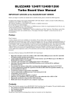
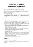
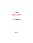
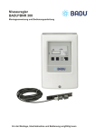
CYBERSTORM
High Performance
68040/68060
Accelerator System
for the AMIGA 4000
UsersManual
68040/68060
Beschleunigersystem
für den AMIGA 4000
Benutzerhandbuch
CYBERSTORM
Modulares 68040/68060-Beschleunigersystem für den Amiga 4000
Anwenderhandbuch
3. Auflage Februar 1995
Copyright 1994/1995 phase 5 digital products
Homburger Landstraße 412
60433 Frankfurt/Main
Konzeptionelles Design
Hardware-Design:
Software (für 68060-Version):
Platinen-Layout
Dokumentation
Gerald Carda, Wolf Dietrich
Thomas Rudloff, Gerald Carda
Ralph Schmidt
Gerald Carda, Uwe Trebbien
Michael-W. Hohmann, Uwe Trebbien, Wolf Dietrich
Warenzeichen:
Workbench ™, Intuition ™, AMIGA™, AmigaDOS ™ sind eingetragene Warenzeichen von Commodore Amiga Inc.,
West Chester, USA. Verwendete Produktnamen sind Gebrauchsmuster und/oder Warenzeichen der jeweiligen Hersteller.
Text, Abbildungen, Programme und Hardware wurden mit größter Sorgfalt erarbeitet. Alle Rechte sowie Änderungen in
Technik und Lieferumfang vorbehalten. Die phase 5 digital products kann jedoch für eventuell verbliebene fehlerhafte
Angaben und deren Folgen weder eine juristische Verantwortung noch irgendeine Haftung übernehmen.
Die vorliegende Publikation ist urheberrechtlich geschützt. Alle Rechte vorbehalten. Kein Teil dieses Buches darf ohne
schriftliche Genehmigung der phase 5 digital products in irgendeiner Form durch Fotokopie, Mikrofilm, Text-Datei oder
andere Verfahren reproduziert oder in eine für Maschinen, insbesondere Datenverarbeitungsanlagen, verwendbare
Sprache übertragen werden. Eine Übersetzung dieses Handbuches in andere Sprachen, insbesondere ins Englische oder
Französische bedarf ebenfalls der schriftlichen Genehmigung der phase 5 digital products.
1
1. Einleitung
An dieser Stelle möchten wir uns zuerst bedanken, daß Sie sich für unser Produkt entschieden haben. Sie haben mit dem
CYBERSTORM-System für den AMIGA 4000 ein hochqualitatives und ausgereiftes Produkt erworben, das nicht nur in
umfangreichen Versuchsserien vor seiner Markteinführung getestet und erprobt wurde, sondern in dem sich auch
langjährige Erfahrung in der Entwicklung von Peripherie, im speziellen von Beschleunigersystemen, für den Amiga
widerspiegelt. Darüberhinaus wurden mit dem CYBERSTORM-System aufwendige Konzepte realisiert, die diese
Beschleunigerkarte von auf den ersten Blick vergleichbaren Produkten abheben.
Der hohe Aufwand, der bei der Entwicklung und Feinabstimmung dieser Prozessorkarte betrieben wurde, ist auch
Maßstab bei der Produktion der Geräte gewesen. Dieser Aufwand gewährleistet, daß das CYBERSTORM-System
höchsten Ansprüchen an Qualität, Sicherheit, Kompatibilität und Leistung gerecht wird. Wir hoffen, daß Sie mit diesem
Produkt lange viel Freude haben werden.
Wir möchten Sie an dieser Stelle darum bitten, die diesem Produkt beigefügte Registrationskarte auszufüllen und an uns
einzusenden. Zum einen können wir Sie so über mögliche zukünftige Erweiterungen oder Updates des
CYBERSTORM-Systemes, sowie auch über andere Entwicklungen rund um den Amiga informieren, zum anderen
helfen Sie uns mit Ihrer Meinung, auch in Zukunft die Produkte für den Amiga zu entwickeln und auf den Markt zu
bringen, die Sie sich als Anwender wünschen. Lassen Sie sich aber ruhig einige Tage Zeit mit dem Ausfüllen der
Bewertungen, bis Sie erste Erfahrungen beim Arbeiten mit dem CYBERSTORM-System in Ihrem AMIGA gemacht
haben — Ihre Meinung über die Leistung in der Praxis ist uns wichtig.
phase 5 digital products,
im August 1994
2
2. Lieferumfang
Das System CYBERSTORM 040/40 besteht aus mehreren Platinen, einigen kleinen Zubehörteilen, sowie einer Dokumentation. An dieser Stelle sollten Sie prüfen, ob folgende Teile vorhanden sind:
Die Träger-Platine (CYBERSTORM Carrier)
Das CYBERSTORM CPU-Modul
Das CYBERSTORM RAM-Modul
Ein Isolator aus fester Pappe
Vier Abstandshalter
Eine Registrationskarte
Dieses Handbuch
Sollte eines dieser Teile fehlen wenden Sie sich bitte an den technischen Support unter der Rufnummer 069 / 548 18 44.
Dieser wird Ihnen dann umgehend Ersatz zukommen lassen.
3. Installations-Checkliste
Anhand dieser Liste können Sie feststellen, welche Kapitel Sie lesen sollten um bestimmte Konfigurationen des CYBERSTORM-Systemes zu installieren.
Komplettinstallation der CYBERSTORM-Beschleunigerkarte ohne Speicher
Kapitel 6 Softwareinstallation (Nur CYBERSTORM 68060)
Kapitel 4 Einbau der CYBERSTORM-Beschleuingerkarte
Komplettinstallation der CYBERSTORM-Beschleunigerkarte mit Speicher
Kapitel 6 Softwareinstallation (Nur CYBERSTORM 68060)
Kapitel 4 Einbau der CYBERSTORM-Beschleuingerkarte
Kapitel 5 Speicherausbau
Nachträgliche Installation von Speicher in ein bestehendes System
Kapitel 5 Speicherausbau
Analyse eventuell auftretender Probleme oder Fehlfunktionen
Kapitel 6 Fehlersuche
3
4. Installation
Das CYBERSTORM-System wird in den Prozessorsteckplatz des Amiga 4000 eingesetzt. Dieser befindet sich zwischen der Slot-Platine und dem vorderen Laufwerksschacht. Die Installation der Karte ist nicht sehr schwierig. Falls Sie
jedoch keine Erfahrung beim Einbau von Erweiterungskarten haben, Ihnen nach dem Durchlesen der Anleitung noch
einiges unklar ist, oder wenn Sie es generell bevorzugen, kann auch Ihr Fachhändler, u.U. gegen eine geringe Gebühr,
die Installation vornehmen. Bitte beachten Sie, daß der Einbau in jedem Fall unter Beachtung der gängigen Maßnahmen
gegen Antistatik-Beschädigungen vorgenommen werden muß.
ACHTUNG!
nur 68060
Bei Installation einer CYBERSTORM 68060 muß die Software vor Einbau der Karte installiert werden.
Lesen Sie hierzu bitte erst Kapitel 6 Softwareinstallation
ACHTUNG!
Sie sollten auf alle Fälle vor der Installation des CYBERSTORM-Systems dieses Handbuch durchgelesen
haben, da sonst die Karte oder der Rechner zu Schaden kommen kann!
Wenn Sie im System, in dem das CYBERSTORM eingebaut werden soll, Festplatten installiert haben, auf
denen sich nicht gesicherte Daten befinden, raten wir dringend, VOR Einbau des CYBERSTORMSystems ein Sicherungs-Backup der Festplatte(n) zu erstellen. Jede Neuinstallation von HardwareZubehör birgt das - wenn auch noch so geringe - Risiko einer Beschädigung empfindlicher Komponenten
oder Fehlfunktionen aufgrund unsachgemäßen Einbaus oder Vorgehens in sich; als Folge einer solchen
Beschädigung oder Fehlfunktion können Datenverluste auf bestehenden Festplatten durch Fehlfunktionen
bei der folgenden Inbetriebnahme auftreten. Sollte ggfs. ein Backup auf Diskette wegen großer Datenmenge zu langwierig erscheinen, so fragen Sie Ihren Fachhändler, ob er für Sie die Sicherung (z.B. auf
einen Streamer) und Neuinstallation vornehmen kann, oder ob Sie einen Streamer, evtl. gegen eine
geringe Gebühr, ausleihen können. Wir weisen ausdrücklich darauf hin, daß wir keinerlei Gewährleistung
für Datenverluste übernehmen, die evtl. im Falle einer Fehlfunktion des Systems in Folge des Einbaus der
CYBERSTORM-Systems entstehen.
Falls das Speicher-Modul mit RAM bestückt werden sollte, konfigurieren und bestücken Sie bitte das Modul anhand
der Daten in dem Kapitel Speicherausbau.
Hinweis
Bitte beachten Sie, falls Sie die CYBERSTORM-Karte ohne Prozessor (CPU) erworben haben, daß Sie
zum Ausbau des Prozessors von der A3640 spezielles Werkzeug benötigen. Falls Sie dieses nicht haben,
sollten Sie den Umbau des Prozessors von einer Fachwerkstatt vornehmen lassen.
4.1 Einbau der CYBERSTORM-Beschleunigerkarte
1.
Schalten Sie Ihren Computer aus.
2.
Lösen Sie alle Kabel vom Rechner (Monitor, Maus, Tastatur, sonstige Schnittstellen).
3.
Lösen Sie die zwei Schrauben die den Gehäusedeckel halten. Diese befinden sich auf der Rückseite links und rechts
oben.
4.
Entfernen Sie vorsichtig den Gehäusedeckel durch Hochklappen. Falls Ihnen dies nicht gelingt, oder falls Sie weitere Informationen benötigen, lesen Sie bitte in Ihrem Amiga-Benutzerhandbuch nach.
4
5.
Um die Prozessorplatine auszutauschen ist es nötig, auch die Festplatte im hinteren Laufwerksschacht auszubauen.
Abbildung 4.1:
Durch leichtes seitliches Kippen
läßt sich die CPU-Platine nach
dem Lösen vom Steckverbinder
aus dem Gehäuse nehmen.
Zum Ausbau der Festplatte in dem hinteren Laufwerksschacht müssen nur die vier Befestigungsschrauben gelöst und
die Platte samt Halterung angehoben werden. Die Anschlußkabel sind lang genug, um die Festplatte auf dem Netzteil
abzulegen, ohne die Kabel lösen zu müssen.
Abbildung 4.2:
Auf diesen Abstandshaltern muß
die Trägerplatine aufgesetzt
werden.
6.
Danach wird die Prozessorplatine wie in Abbildung 4.1 aus dem Rechner genommen. Falls die Platine sehr fest
sitzt, sollte darauf geachtet werden, daß auch alle vier Abstandshalter lose sind. Die Platine kann nun durch leichtes
Kippen aus dem Rechner herausgenommen werden.
Falls die Abstandshalter nicht in der Hauptplatine sondern auf der Prozessorplatine sitzen, stecken Sie diese bitte in die
dafür vorgesehenen Bohrungen auf der Hauptplatine zurück, wie in Abbildung 4.2 zu sehen. Dies ist nötig, um einen
möglichst einfachen Einbau des CYBERSTORM-Systems zu ermöglichen. Für Besitzer eines A4000/030 liegen
zusätzliche Abstandshalter bei.
7.
Vor Einbau der Trägerplatine müssen die zwei Clock-Jumper, die auf dem Mainboard unter der CPU-Platine mit
INT und EXT beschriftet sind (siehe Abbildung 4.3), auf die richtige Position gesetzt werden. Für den Betrieb der
CYBERSTORM müssen diese auf die Position a) bei einer synchronen CYBERSTORM 68040/25MHz und einer
CYBERSTORM 68060 auf EXT und b) bei einer asynchronen CYBERSTORM 68040/40MHz auf INT gesetzt
werden. Je nachdem, ob Sie das CYBERSTORM in einem AMIGA 4000/030 oder AMIGA 4000/040 einbauen,
sind diese Jumper auf die Position EXT oder auf die Position INT gesetzt. Bitte beachten Sie, daß ein Betrieb der
CYBERSTORM in der falschen Position nicht möglich ist, und der Rechner bei einer solchen falschen Position
nicht mehr bootet.
5
Abbildung 4.3:
Position der Clock-Jumper, die in
jedem Fall korrekt gesetzt werden
müssen.
Abbildung 4.4:
Einbau des Cyberstorm-Carriers.
Die Kreise markieren die Position
der Bohrungen, in die die Abstandshalter einrasten müssen.
8.
Die Trägerplatine wird in den Rechner eingebaut, indem sie zuerst auf den Abstandshaltern aufgesetzt und dann
festgedrückt wird (siehe Abbildung 4.4). Dabei ist zu beachten, daß die Platine sowohl von den Abstandshaltern
gehalten wird, als auch vollständig im Prozessorstecker sitzt.
Vorher sollten noch, sofern nötig, die Jumper auf der Trägerplatine anhand untenstehender Tabelle gesetzt bzw.
überprüft werden.
IPEND
CBR
DIAG Enable
ROM Size
ROM Cnt
Gesteckt, falls kein Prozessor auf der Hauptplatine
Gesteckt, falls Prozessor auf der Hauptplatine
1 und 2 verbunden um das DiagROM einzuschalten;
2 und 3 verbunden, falls das DiagROM nicht vorhanden oder nicht verwendet werden soll
1 und 2 verbunden für 16 Bit ROM’s;
2 und 3 verbunden für 8 Bit ROM (Rom 0)
1 und 2 verbunden falls zwei ROM’s installiert sind;
2 und 3 verbinden, falls ein ROM installiert ist
Bitte verändern Sie die Jumper ausschließlich in den oben genannten Fällen. Die Jumper sind vom Werk aus
optimal gesetzt, so daß in der Regel keine Änderung nötig ist.
6
ACHTUNG!
Bitte beachten Sie, daß die Jumper auf dem CYBERSTORM-System niemals bei eingeschaltetem
Rechner umgesteckt werden dürfen. Dadurch können Beschädigungen an der Hardware des
CYBERSTORM verursacht werden. Schalten Sie vor dem Umstecken eines Jumpers in jedem Fall das
Gerät ab.
9.
Das CPU-Modul wird auf der Trägerplatine aufgesetzt. Dazu werden zuerst zwei der mitgelieferten Abstandshalter in
die Bohrungen auf der Trägerplatine gesteckt, wie in Abbildung 4.5 zu sehen.
Abbildung 4.5:
Position der Abstandhalter für das
CPU-Modul auf dem
CYBERSTORM Carrier-Board.
Dann wird das CPU-Modul zuerst auf die Abstandshalter aufgesetzt und anschließend in den Stecker gedrückt (siehe
Abbildung 4.6). Auch hierbei ist zu beachten, daß das CPU-Modul sowohl von den Abstandshaltern gehalten wird, als
auch komplett in dem Stecker sitzt.
Abbildung 4.6:
Einbau des CPU-Moduls. Die
weißen Kreise markieren die
Position der Bohrungen für die
Abstandshalter.
7
Der CPU-Lüfter muß noch mit Strom versorgt werden. Dazu wird ein breiter Stromanschluß (wie er normalerweise für
Festplatten verwendet wird) mit der Buchse am Ende des Kabels vom Lüfter verbunden, wie in der untenstehenden
Abbildung 4.7.
Hinweis
Bitte beachten Sie, daß aufgrund der höheren Wärmeentwicklung der schnelleren CPUs des
CYBERSTORM-Systems die korrekte Funktion des Lüfters absolut erforderlich ist. Ggfs. sollten Sie
daher, vorausgesetzt Sie sind mit technischen Geräten erfahren, durch kurzes Einschalten des Rechners
überprüfen, ob der sich Lüfter ordnungsgemäß dreht, bevor Sie das Gehäuse schließen. Sollte dies nicht
der Fall sein, überprüfen Sie bitte den korrekten Sitz des Anschlußkabels. Vermeiden Sie aber in jedem
Fall, irgendein Teil im Innern des Rechners zu berühren, solange dieser offen ist, da das Gerät unter Strom
steht und durch jegliche Berührung beschädigt werden kann. Wenn Sie keine Erfahrung mit elektrischen
bzw. technischen Geräten haben, lassen Sie Einbau und Überprüfung durch Ihren Fachhändler vornehmen!
Abbildung 4.7:
Der korrekt angeschlossene Lüfter.
10.
Als letztes wird dann das RAM-Modul in den Stecker auf der Trägerplatine gesteckt (siehe Abbildung 4.8). Hierzu
sollte erst die Speicherbestückung des RAM-Moduls (wie in Kapitel 5 beschrieben) vorgenommen werden. Die
Bestückungsseite des RAM-Modules muß beim Einbau in Richtung Laufwerksträger zeigen. Danach stecken Sie
bitte die Isolator-Pappe zur Isolierung zwischen das RAM-Modul und die Backplane (Zorro-Slot-Platine) des
AMIGA 4000.
Abbildung 4.8:
Einsetzen des RAM-Moduls.
8
20
Hierzu verwenden Sie bitte die beiliegende Isolator-Pappe mit der Aufschrift „RAM-Modul-Isolation“. Wenn die Pappe
entlang der Markierungen gefaltet wird, kann sie auf die Trägerschiene über der Backplane gelegt und ggf. mit einem
Klebestreifen fixiert werden. Diese Isolation vermeidet, daß das RAM-Modul die Backplane berührt, wenn z.B. der
Rechner im eingeschaltetem Zustand versehentlich einen Stoß abgekommt.
Falls das RAM-Modul nicht mit Speicher bestückt wurde, braucht es nicht unbedingt eingebaut zu werden. Das
CYBERSTORM-System macht in dem Falle keinen Unterschied.
So sollte es aussehen, wenn die Beschleunigerkarte eingebaut ist:
Abbildung 4.9:
Das fertig installierte
CYBERSTORM-System
11.
Die Festplatte wird samt Halterung wieder in umgekehrter Reihenfolge eingebaut, wie sie ausgebaut wurde.
12.
Zuletzt schließen Sie das Gehäuse wieder, schrauben es zu, und verbinden alle Kabel wieder wie zuvor mit dem
Rechner. Damit ist der Einbau abgeschlossen. Zum Betrieb des CYBERSTORM 040 wird auch keine Veränderung
in der Software-Installation oder zusätzliche Software benötigt. Besitzer eines A4000/030 sollten allerdings
überprüfen, daß die 68040.library im libs:-Verzeichnis Ihrer Systemfestplatte vorhanden ist.
5. Speicherausbau
Das RAM-Modul wird mit ganz normalen SIMMs (Single Inline Memory Modules) in 32-bit oder 36-bit Datenbreite wie sie auch für den Speicher auf der Hauptplatine des A4000 verwendet werden - bestückt. Es können SIMMs mit
Kapazitäten von 4, 8, 16 oder 32 MByte pro Modul verwendet werden. Die 36-bit Module sind SIMMs mit sogenannter
Parität, diese wird bei Einsatz auf dem RAM-Modul ignoriert. Zur Zeit (August 1994) sind beide Modul-Typen
erhältlich, jedoch sind die Module ohne Parität meist erheblich billiger.
Bei der Speicheraufrüstung können die Speicherbänke einzeln bestückt werden. Und auch verschiedene ModulKapazitäten können gemischt werden. Hierbei ist allerdings zu beachten, daß die Module mit der größten Kapazität immer zuerst in Bank 0 gesteckt werden (siehe auch Tabelle Speicherkonfiguration Teil 1 und 2).
5.1 Einsetzbare SIMM-Typen
Auf der Folgeseite befindet sich eine Tabelle die beschreibt, wie die Bänke mit welchen Modulen bestückt werden
müssen, um einen bestimmten Speicherausbau zu realisieren. Die SIMMs sollten Zugriffszeit von längstens 70 ns
haben. So Ihr AMIGA mit 4 MByte-Modulen ausgestattet ist und diese eine Zugriffzeit von 70 ns oder besser haben,
sollten Sie diese von der Hauptplatine des A4000s auf das RAM-Modul umstecken, da der Amiga keinen Burst-Zugriff
in den Speicher auf der Hauptplatine erlaubt.
9
Zur Konfiguration des RAM-Moduls sollte es ausgebaut werden, da Sie dann die Jumper am besten erreichen können.
Die Darstellung der folgenden Tabelle zeigt die Jumper-Positionen bei Sicht von oben auf die Jumper.
Speicher
insgesamt:
-------------------------Bank-Bestückung auf------------------------Bank0
Bank1
Bank2
Bank3
4 / 8 / 12 / 16 MB
8 / 12 / 16 / 20 MB
16 / 20 / 24 / 28 MB
32 / 36 / 40 / 44 MB
16 / 20 / 24 MB
24 / 28 / 32 MB
40 / 44 / 48 MB
32 / 36 / 40 MB
48 / 52 / 56 MB
64 / 68 / 72 MB
24 / 28 MB
32 / 36 MB
48 / 52 MB
40 / 44 MB
56 / 60 MB
72 / 76 MB
48 / 52 MB
64 / 68 MB
80 / 84 MB
96 / 100 MB
32 MB
40 MB
56 MB
48 MB
64 MB
80 MB
56 MB
72 MB
88 MB
104 MB
64 MB
80 MB
96 MB
112 MB
128 MB
4 / 0 MB
8 MB
16 MB
32 MB
8 MB
16 MB
32 MB
16 MB
32 MB
32 MB
8 MB
16 MB
32 MB
16 MB
32 MB
32 MB
16 MB
32 MB
32 MB
32 MB
8 MB
16 MB
32 MB
16 MB
32 MB
32 MB
16 MB
32 MB
32 MB
32 MB
16 MB
32 MB
32 MB
32 MB
32 MB
4 / 0 MB
4 / 0 MB
4 / 0 MB
4 / 0 MB
8 MB
8 MB
8 MB
16 MB
16 MB
32 MB
8 MB
8 MB
8 MB
16 MB
16 MB
32 MB
16 MB
16 MB
32 MB
32 MB
8 MB
8 MB
8 MB
16 MB
16 MB
32 MB
16 MB
16 MB
32 MB
32 MB
16 MB
16 MB
32 MB
32 MB
32 MB
4 / 0 MB
4 / 0 MB
4 / 0 MB
4 / 0 MB
4 / 0 MB
4 / 0 MB
4 / 0 MB
4 / 0 MB
4 / 0 MB
4 / 0 MB
8 MB
8 MB
8 MB
8 MB
8 MB
8 MB
16 MB
16 MB
16 MB
32 MB
8 MB
8 MB
8 MB
8 MB
8 MB
8 MB
16 MB
16 MB
16 MB
32 MB
16 MB
16 MB
16 MB
32 MB
32 MB
RAM-JumperEinstellung
4 / 0 MB
4 / 0 MB
4 / 0 MB
4 / 0 MB
4 / 0 MB
4 / 0 MB
4 / 0 MB
4 / 0 MB
4 / 0 MB
4 / 0 MB
4 / 0 MB
4 / 0 MB
4 / 0 MB
4 / 0 MB
4 / 0 MB
4 / 0 MB
4 / 0 MB
4 / 0 MB
4 / 0 MB
4 / 0 MB
8 MB
8 MB
8 MB
8 MB
8 MB
8 MB
8 MB
8 MB
8 MB
8 MB
16 MB
16 MB
16 MB
16 MB
32 MB
Tabelle: Speicherkonfiguration
5.2 Die Speicherbänke
Auf dem RAM-Modul entspricht eine Speicherbank einem SIMM-Steckplatz. Die Bank 0 befindet sich unten (also am
nähesten zu dem Platinenstecker) und die Bank 3 am oberen Ende der Platine. Wie aus der Tabelle Speicherkonfiguration zu ersehen ist, muß immer das SIMM mit der größten Kapazität in die niedrigste freie Bank gesteckt werden.
5.3 Einsetzen von SIM-Modulen
Bei einseitig bestückten SIMMs muß beim Einsetzen nur darauf geachtet werden, daß die bestückte Seite nach oben
zeigt (von der Platine weg). Beim Einsetzen von zweiseitig bestückten SIMMs muß darauf geachtet werden, daß die
Einkerbung des SIMMs auf der linken Seite (der Platinenstecker des RAM-Moduls zeigt nach unten) ist. Das Einsetzen
ist generell sehr einfach, da auf dem RAM-Modul hochwertige SIMM-Sockel verwendet wurden.
10
Abbildung 5.1:
Einsetzen eines SIM-Moduls
Am einfachsten lassen sich die SIMMs dann einsetzen, wenn das RAM-Modul noch nicht eingebaut ist. Erfahrene Anwender können die SIMMs auch bei eingebautem RAM-Modul einsetzen. Legen Sie das RAM-Modul mit dem Platinenstecker nach unten (also auf Sie zu) vor sich auf eine ebene und stabile Unterlage. Nehmen Sie das SIM-Modul mit
der größten Kapazität und halten Sie es in einem 45 Grad Winkel so, daß die Kontaktleiste auf Sie gerichtet ist und die
Einkerbung auf der Platine des SIMMs auf der linken Seite ist. In dieser Haltung läßt sich das SIMM am besten einsetzen. Beginnen Sie mit dem Bestücken bei der RAM-Bank 0. Wenn das SIMM wie oben beschrieben in den Sockel
gesetzt wurde, muß es noch mit sanftem Druck nach hinten unten in die korrekte Lage von ca. 30 Grad gebracht werden. Dazu drücken Sie am besten mit den beiden Zeigefingern auf die linke und die rechte obere Ecke des lockeren
SIMMs. Falls es nicht gleich einrastet, können Sie auch mit den Zeigefingern daran wackeln, so daß es leichter einrastet. Der Sockel hat links und rechts neben den beiden Löchern im SIM-Modul je ein Häkchen. Diese müssen korrekt
über dem SIMM eingeschappt sein. Verfahren Sie genauso weiter mit dem SIMM mit der nächstkleineren Kapazität.
11
6. Softwareinstallation
(nur 68060)
Die mitgelieferte Software umfaßt die notwendigen Libraries zum Betrieb der 68060 CPU, den Befehl CPU060, ein
Äquivalent zum CPU Befehl des Betriebssystems sowie einige Tools für den Betrieb der 68060 CPU.
Durch die Installation wird die 68040.library umbenannt und die Libraries 68040.library und 68060.library in das LIBS:
Verzeichnis kopiert. Desweiteren wird der CPU060 Befehl nach C: kopiert und eine Schublade mit der Bezeichnung
SOFT060, die die Tools für den Betrieb der 68060 CPU enthält, in der Systempartition erzeugt.
ACHTUNG!
Die Installation sollte entweder noch mit der alten CPU-Karte erfolgen, oder falls dies nicht möglich ist,
unter Verwendung der Option „Booten ohne Startup-Sequence“ aus dem Bootmenu. Bei Verwendung
dieser Option geben Sie nach dem Systemstart in dem CLI Fenster den Befehl loadwb ein.
Sollte der Betrieb einer 68030 oder 68040 CPU nötig sein, brauchen Sie keine Veränderung der installierten Software
vorzunehmen. Die aktuelle Version der bei der CYBERSTORM mitgelieferten 68040.library erkennt automatisch den
eingesetzten Prozessor und lädt die benötigte Library nach.
Die Installation der Software wird durch ein Installationsskript vorgenommen. Legen Sie die mitgelieferte Diskette ein
und öffnen Sie durch Doppelklicken mit der Maus die Disktte. Sie sollten vor der endgültigen Installation die auf der
Diskette vorhandene LiesMich Datei durch Doppelklicken aufrufen. In diesem Text sind die aktuellen Informationen
zur Software enthalten. Die Software wird dann durch Doppelklicken auf das INSTALL Icon installiert.
Die Programme im SOFT060 Verzeichnis haben eine eigene Dokumentation auf der Diskette, der Befehl CPU060 hat
zusätzlich zu den Argumenten des CPU Befehls folgende Argumente:
(NO)SUPERSCALAR
(de)aktiviert den Superscalar Modus des Prozessors
(NO)BRANCHCACHE
(de)aktiviert den Branchcache
12
7. Fehlersuche
Treten nach dem Einbau eines Cyberstorm-Systems Probleme auf, so können diese folgende Ursachen haben:
1.
Bei manchen Amiga 4000/040 Rechnern (speziell Revision D, mit 68030-Prozessor geliefert) wurde auf der Hauptplatine kein Quarz eingesetzt. Für einen Betrieb der CYBERSTORM in diesen Rechnern ist eine Nachrüstung des
Quarzes unbedingt erforderlich.
2.
Bei einer Übertaktung des AMIGA 4000-Mainboards (Aufrüstung von 25MHz auf höhere Geschwindigkeit) arbeitet
das CYBERSTORM-System entweder fehlerhaft oder garnicht. In einem solchen Fall muß das A4000-Mainboard
wieder auf die originale Taktfrequenz von 25 MHz zurückgerüstet werden.
3.
Falls Probleme mit dem Speicher auftreten (z.B. dadurch zu erkennen, daß vorher einwandfreie, mit Programmen
wie LHarc o.ä. gepackte Archives nun Fehler enthalten), sollte der Jumper JPA auf dem Cyberstorm Carrier-Board
umgesteckt werden. Dies erhöht die Toleranz gegenüber Speichermodulen, die zu hohe kapazitive Last aufweisen
(solche sind nur vereinzelt im Handel, aber nicht von anderen Typen zu unterscheiden). Falls danach immer noch
Probleme auftreten, so setzten Sie sich bitte mit unserem technischen Support in Verbindung.
4.
Eine andere Ursache, warum die CYBERSTORM nicht funktioniert, kann darin begründet sein, daß Sie entweder
einen Fastlane mit der falschen Device-Version verwenden (-> bitte mitgeliefertes Device-Ugrade einsetzen), oder
Sie verwenden einen Fastlane mit der Platinen Revision 2.1 (-> bitte setzten Sie sich mit dem Support in
Verbindung). Dies ist daran zu erkennen, das Schreib-/Lesefehler auf der Festplatte auftreten, oder der Rechner gar
nicht bootet (HD-Led leuchtet dabei ständig).
5.
Falls die CYBERSTORM überhaupt nicht funktioniert, kann es daran liegen, daß bei manchen Amiga 4000 Hauptplatinen der Bestückungsdruck falsch ist. Bitte überprüfen Sie das anhand des Schaubildes in Kapitel 4.
6.
Bei 68060 Systemen deutet ein sich immer wiederholendes Booten auf eine fehlende Installation der benötigten
Software hin. In diesem Falle müssen Sie gemäß Kapitel 6 Softwareinstallation die Software nachträglich installieren. Der Rechner muß hierzu durch Drücken beider Maustasten beim Systemstart und anschließender Auswahl
des Menupunktes „Booten ohne Startup-Sequence“ gestartet werden. Sollten hierbei Probleme mit der Bildschirmdarstellung auftreten (z. B. weil der Monitor die PAL Frequenz nicht synchronisieren kann), so müssen Sie das original CPU Board wieder einbauen.
Im Falle anderer Probleme wenden Sie sich bitte an unsere technische Hotline (siehe Kapitel 9).
13
8. Garantiebestimmungen
Auf diese CYBERSTORM-Beschleunigerkarte gewährt die phase 5 digital products eine Garantie von 12 Monaten auf
Bauteile und Verarbeitung. Die Garantiezeit beginnt mit dem Verkaufsdatum an den registrierten Benutzer. Innerhalb
dieser Gewährleistungsfrist beseitigen wir nach unserer Wahl durch Umtausch oder Reparatur alle Mängel, die auf Material- oder Herstellungsfehlern beruhen. Durch die Ausführung von Garantieleistungen wird die Garantiefrist in keiner
Weise berührt.
Ausgeschlossen werden Garantieleistungen für Beschädigungen oder Funktionsstörungen, die aufgrund äußerer Einwirkungen oder unsachgemäßer Benutzung (speziell auch unautorisierter Reparatur) verursacht wurden. Veränderungen
an der Hardware, gleich welcher Art, führen automatisch zum Erlöschen des Garantieanspruchs.
Ausgeschlossen werden ebenso Garantieleistungen für Fehlfunktionen oder Funktionsstörungen am CYBERSTORMSystem, an anderen im/am AMIGA angeschlossenen Geräten oder am AMIGA selbst, die nach dem Einbau der
CYBERSTORM oder späterer Veränderungen des Systems (wie z.B. Einbau neuer Erweiterungen) auftreten, sofern
nicht zweifelsfrei nachgewiesen werden kann, daß ein technischer Defekt des CYBERSTORM-Systems Ursache der
Fehlfunktion oder Funktionsstörung ist. Ausdrücklich werden hierbei auch Veränderungen an der Hardware und/oder
Software des AMIGA eingeschlossen, die durch die Firma Commodore in Form von Reparaturen, Nachbesserungen
oder System-Updates vorgenommen werden.
phase 5 digital products übernimmt keinerlei Gewährleistung dafür, daß dieses Produkt für eine bestimmte Anwendung
geeignet ist. Weiterhin übernehmen wir keinerlei Haftung für Defekte oder Schäden an anderen Geräten als dem
CYBERSTORM-System, sowie ausdrücklich auch Verluste von Daten, die in mittelbarem oder unmittelbarem Zusammenhang mit dem Einsatz der CYBERSTORM-Beschleunigerkarte stehen oder zu stehen scheinen, selbst wenn wir
vorher auf die Möglichkeit eines solchen Zusammenhangs hingewiesen worden sind. Für mitgelieferte Speichermodule
oder anderes Zubehör gelten ausschließlich die Garantiebestimmungen des jeweiligen Herstellers. Desweiteren finden
die Gewährleistungsbestimmungen unserer Allgemeinen Geschäftsbedingungen Anwendung.
Bitte senden Sie in jedem Fall Ihre Registrationskarte unter Angabe von Kaufdatum und Seriennummer des
CYBERSTORM-Systems ein, damit im Falle von Problemen oder Garantieabwicklungen diese ohne weitere Anforderungen oder Verzögerungen bearbeitet werden können.
14
9. Garantieabwicklung, Rücksendungen
Die Abwicklung von Garantiefällen, wie auch sonstige technische Beratung oder Service, erfolgt innerhalb
Deutschlands direkt über unseren Support-Service. Bitte wenden Sie sich an:
phase 5 digital products
Homburger Landstraße 412
D - 60433 Frankfurt
Telefon Technische Hotline: (069) 548 18 44, Fax (069) 5481845
Support-Mailbox (ab Mai 95): (069) 54 24 61
Die technische Hotline ist Mo.-Do. von 1330 bis 1730, Fr. von 1300 bis 1500 Uhr (CET) besetzt.
In allen anderen Ländern wenden Sie sich zur Garantieabwicklung bitte direkt an unsere Distributoren oder Ihren
Fachhändler.
Bitte beachten Sie, daß Rücksendungen nur nach vorheriger Absprache mit und Autorisation von unserem Support
angenommen werden können. Dieser erteilt Ihnen eine RMA-Nummer, die gut sichtbar auf der Einsendung vermerkt
sein muß. Bitte beachten Sie, daß wir bei Einsendungen ohne RMA-Nummer eine Bearbeitungspauschale von DM
25,- berechnen müssen. Unfreie Einsendungen können nicht angenommen werden.
Sofern bei autorisierten Rücksendungen kein Defekt feststellbar ist, wird eine Bearbeitungspauschale von DM 50,(Stand: August 1994) erhoben. Wird ein Defekt festgestellt, der nicht unter die Garantieabwicklung fällt, so werden die
Bearbeitungspauschale und bei Reparatur zusätzlich eine vom Defekt anhängige Reparaturgebühr berechnet.
Für Versandschäden, die auf mangelhafte Verpackung bei der Einsendung von Geräten zurückzuführen sind, kann keine
Haftung übernommen werden. Verwenden Sie bei der Einsendung einer CYBERSTORM-Beschleunigerkarte immer die
Originalverpackung und zusätzlich eine stabile Umverpackung (z.B. Postpaket) und ggfs. Füllmaterial (z.B. Zeitungspapier).
15
Anhang A Jumperpositionen
Pos 2-3 JPC
nur für Tests
nicht ändern
JPD Pos 2-3
nur für Tests
nicht ändern
Pos 2-3 JPB
nur für Tests
nicht ändern
CBR
Siehe Text
Pos 1-2 CCLK
nur für Tests
nicht ändern
ROM SIZE
Siehe Text
IPEND
siehe Text
DIAG ENABLE
Siehe Text
JPA
Siehe Text
MB BURSTSiehe Text
ROM CNT
Siehe Text
MB BURSTSiehe Text
Pin 1 ist bei allen Jumpern im
Schaubild der quadratisch
dargestellte Kontakt.
IPEND
CBR
DIAG Enable
ROM Size
ROM Cnt
JPA
MB Burst
CLK offen
nur für Tests
nicht ändern
Gesteckt, falls kein Prozessor auf der Hauptplatine
Gesteckt, falls Prozessor auf der Hauptplatine
1 und 2 verbunden um das DiagROM einzuschalten;
2 und 3 verbunden, falls das DiagROM nicht vorhanden oder nicht verwendet werden soll
1 und 2 verbunden für 16 Bit ROM’s;
2 und 3 verbunden für 8 Bit ROM (Rom 0)
1 und 2 verbunden falls zwei ROM’s installiert sind;
2 und 3 verbunden, falls ein ROM installiert ist
1 und 2 verbunden für normale RAM Zugriffe
2 und 3 verbunden für schnelle RAM Zugriffe
offen für langsame RAM Zugriffe
beide Jumper 1 und 2 verbunden für Burstzugriffe zum Mainboard möglich
beide Jumper 2 und 3 verbunden für Burstzugriffe zum Mainboard nicht möglich
Bei Betrieb einer 68060 CPU ist ein entsprechendes ROM für die Installation der Systempatches notwendig. Das ROM
wird in den mit ROM 0 bezeichneten Sockel bündig zur Unterseite mit der Kerbe nach oben (wie im Sockel) gesteckt.
Dies ist nur beim Upgrade von einem 68040 System zum 68060 System durch den Benutzer durchzuführen. Bei 68060
Vollsystemen ist das ROM bereits ab Werk installiert.
CYBERSTORM
A modular 68040/68060 accelerator system for the Amiga 4000
User Manual
3rd Edition February 1995
Copyright 1994/1995 phase 5 digital products
Homburger Landstraße 412
60433 Frankfurt/Main
Conceptual Design:
Hardware Design:
Software (for 68060 version):
Board Layout:
Documentation:
Gerald Carda, Wolf Dietrich
Thomas Rudloff, Gerald Carda
Ralph Schmidt
Gerald Carda, Uwe Trebbien
Michael-W. Hohmann, Uwe Trebbien, Wolf Dietrich
Copyright 1994 by phase 5 digital products.
All rights reserved. Specifications are subject to change without notice. Workbench™, Intuition™, AMIGA™,
AmigaDOS™ are registered trade names of Commodore-Amiga Inc. Product names used are registered designs and/or
trademarks of the relevant manufacturer.
The text, illustrations, programs and hardware have been produced with the utmost care. All rights and changes to the
technology and scope of supply are reserved. Phase 5 digital products accepts neither legal responsibility nor liability
for any errors remaining in the data or the consequences thereof.
This publication is protected by copyright. All rights are reserved. No part of this manual may be reproduced by
photocopying, microfilm, text file or other process or be transferred into a language used for machines, in particular
data processing equipment, without the express written authorisation of phase 5 digital products. Translation of this
manual into other languages, especially English or French, must also be authorised by phase 5 digital products.
1
1. Introduction
We would first like to thank you for choosing the CYBERSTORM system for the AMIGA 4000. You are now the owner
of a high quality, mature product, which has not only been tested in extensive trials prior to being brought onto the
market, but which also reflects many years of experience in the development of peripherals for the Amiga, especially
accelerator systems. Much time and money has been invested in the CYBERSTORM system concept which makes it
clearly stand out from other similar products.
A lot of money has been spent not only in developing and refining this processor card but also in the production of the
devices. This level of expenditure guarantees that the CYBERSTORM system will meet the highest requirements of
quality, security, compatibility and performance. We hope that this product will provide you with countless hours of
trouble-free operation.
We would ask you to complete and return the registration card accompanying this product. This will enable us to keep
you informed of any future expansions or updates to the CYBERSTORM system and of other developments for the
Amiga. It will also provide us with important feedback allowing us to develop products for the Amiga which you as a
user actually want. Please take a few days to complete your assessment and to establish your first impressions of the
function of CYBERSTORM system in your AMIGA. Your opinion as to its performance in practice is very important to
us.
phase 5 digital products, August 1994
2
2. Scope of Supply
The CYBERSTORM 040/40 consists of several boards, some small accessories and the documentation. At this point
you should check that you have the following parts:
•
•
•
•
•
•
•
The carrier board (CYBERSTORM Carrier)
The CYBERSTORM CPU module
The CYBERSTORM RAM module
An isolator made of firm cardboard
Four spacers
A registration card
This manual
If you are missing any of these items please contact our technical support centre on Tel: 069/548 18 44. We will arrange
for a replacement item to be despatched.
3. Installation Checklist
This list should enable you to decide which chapters you will need to read to install a specific configuration of the
CYBERSTORM system.
Complete installation of the CYBERSTORM accelerator card without memory
Chapter 6 Software Installation (Only CYBERSTORM 68060)
Chapter 4 Installing the CYBERSTORM Accelerator Card
Complete installation of the CYBERSTORM accelerator card with memory
Chapter 6 Software Installation (Only CYBERSTORM 68060)
Chapter 4 Installing the CYBERSTORM Accelerator Card
Chapter 5 Memory Configuration
Subsequent installation of memory in an existing system
Chapter 5 Memory Configuration
Analysis of any problems or function faults
Chapter 6 Fault Finding
3
4. Installation
The CYBERSTORM system is to be installed in the processor slot of the Amiga 4000. This is located between the slot
board and the front drive slot. It is not very difficult to install the card, but if you prefer because you have had little
experience of installing expansion cards or something is unclear after reading through the instructions, your dealer can
undertake the installation for a small fee. Please note that the installation should always be performed using the
common methods to prevent anti-static damage.
Attention
68060 only
If you install a CYBERSTORM 68060 the software installation has to be done prior to the hardware
installation. Please refer to Chapter 6 Software Installation before proceeding!
ATTENTION!
You must read this manual before installing the CYBERSTORM system, otherwise you could damage the
card or the computer.
If you have disk drives installed on the system in which you wish to install the CYBERSTORM which
contain data that has not been backed-up, then for security reasons, we strongly advise backing-up the
hard drive BEFORE installing the CYBERSTORM system. Each new installation of hardware accessories
involves a risk (even if it is very small) of damage to sensitive components or malfunctions due to
unsuitable installations or procedures. The consequence of such damage or malfunctions could be data
loss on existing disk drives caused by malfunctions during the subsequent commissioning. If it would take
too long to back-up the data onto diskettes because of the large amount of data, then ask your dealer
whether he can carry out the back-ups (e.g. on a streamer) and new installation for you, or whether you
can hire a streamer, at a small charge. We accept absolutely no liability for loss of data that may arise in
the case of a system malfunction as a result of the installation of the CYBERSTORM system.
If the memory module is to be fitted with RAM, then configure and fit the module using the data in the Memory
Configuration Chapter.
Advice
If you have bought a CYBERSTORM card without a processor (CPU) please note that you will require a
special tool to remove the processor from the A3640. If you do not have this you should have the
processor conversion performed by a specialist workshop.
4.1 Installing the CYBERSTORM Accelerator Card
1.
Switch your computer off.
2.
Disconnect all cables from your computer (monitor, mouse, keyboard, other interfaces).
3.
Remove the two screws that secure the casing cover. These are located on the back at the top left and right.
4.
Remove the casing cover by carefully lifting it up. If you cannot do this, or if you require further information,
please consult your Amiga User Manual.
4
5.
To exchange the processor board it is also necessary to remove the hard drive from the rear drive slot.
To remove the hard drive from the rear drive slot remove the four fixing screws and lift out both the disk and its
holder. The cable set is long enough to allow the disk to fee placed on the power supply unit without having to disconnect the cables.
Picture 4.1:
After having removed the CPU
board from the connector, tilt it
slightly side to side to remove it
from the casing.
6.
Next remove the processor board from the computer, as shown in Picture 4.1. If the board is installed firmly ensure
that all four spacers are loose. The board can then be taken out of the computer using a gentle rocking motion.
Picture 4.2:
The carrier board must be
positioned on these spacers.
If the spacers are on the processor board instead of on the main board, then replace them in the holes provided on
the main board, as shown in Picture 4.2. This will make it easier to install the CYBERSTORM system. Extra spacers are provided for owners of a A4000/030.
7.
Before installing the carrier board, the two clock jumpers labelled INT and EXT on the main board under the CPU
board (see Picture 4.3) must be set to the correct position. They should be set to position a) for a synchronous
CYBERSTORM 68040/25 MHz or CYBERSTORM 68060/50 MHz on EXT and to b) for an asynchronous
CYBERSTORM 68040/40 MHz on INT. Depending on whether you are installing the CYBERSTORM in an
AMIGA 4000/030 or AMIGA 4000/040, these jumpers must be set to the INT or EXT position. Please note that it is
not possible to operate the CYBERSTORM with these jumpers set in the incorrect position and the computer will
not boot up.
5
Picture 4.3:
Position of the clock jumper which
must always be set correctly.
Picture 4.4:
Installing the CYBERSTORM
carrier board. The circles mark the
position of the holes in which the
spacers should be engaged.
8.
Install the carrier board in the computer by first placing it on the spacers and then pressing down firmly (see Picture
4.4). When doing this ensure that the board is both held by the spacers and also sitting correctly in the processor
slot.
If necessary, you should have previously set the jumpers on the carrier board to the positions shown in the table below.
IPEND
CBR
DIAG Enable
ROM size
ROM Cnt
enabled, if no processor on the main board
enabled, if processor on the main board
1 and 2 connected to switch on the DiagROM;
2 and 3 connected if the DiagROM is not available or will not be used
1 and 2 connected for 16 bit ROMs;
2 and 3 connected for 8 bit ROMs (ROM 0)
1 and 2 connected if two ROMs are installed;
2 and 3 connected if one ROM is installed
Please only change the jumpers for the conditions stated above. As a rule it is not necessary to change
them as they are set to the optimal settings in the factory.
6
ATTENTION!
Please note that the jumpers on the CYBERSTORM system must never be adjusted whilst the computer is
switched on. This can cause damage to the CYBERSTORM hardware. Always switch the computer off
before changing the position of a jumper.
9.
Place the CPU module onto the carrier board by first placing two of the spacers provided in the holes on the carrier
board, as in Picture 4.5.
Picture 4.5:
Position of the spacers for the
CPU module on the
CYBERSTORM carrier board.
Then place the CPU module on the spacers and press it into the slot (see Picture 4.6). Take care to ensure that the CPU
module is both held by the spacers and sitting correctly in the slot.
Picture 4.6:
Installing the CPU module. The
white circles mark the positions of
the holes for the spacers.
7
The CPU fan must be re-connected to the power by connecting a wide power connector (as normally used for the hard
drives) to the socket at the end of the cable from the fan, as shown in Picture 4.7 below.
Advice
Please note that because of the amount of heat generated by the fast CPU’s on the CYBERSTORM
system it is absolutely necessary for the fan to function correctly. If you have experience of technical
devices then, before closing the casing, you should check whether the fan is revolving correctly by
switching the computer on briefly. If it is not working correctly, check that the cable is connected
properly. Avoid touching any other part of the inside of the computer whilst doing this as the device can
be damaged by any contact whilst under power. If you have no experience with electrical or technical
devices, get your dealer to carry out the installation and checks.
Picture 4.7:
The correctly connected fan.
10.
Finally, place the RAM module into the socket on the carrier board (see Picture 4.8). The RAM module must first
have been fitted with memory (as described in Chapter 5). The installation side of the RAM module must point towards the drive holder when installed. Place the isolation cardboard between the RAM module and the backplane
(Zorro slot board) of the AMIGA 4000.
Picture 4.8:
Installing the RAM module.
8
Please use the enclosed isolation cardboard labelled „RAM Module Isolation“. When the cardboard is folded along the
marking it can be placed on the mounting rail over the backplane and, if necessary, fixed with adhesive tape. This
isolation prevents the RAM module from coming into contact with the backplane if, for example, the computer is
inadvertently knocked whilst it is switched on.
If the RAM module is not fitted with memory it does not necessarily have to be installed. The CYBERSTORM system
does not differentiate in this case.
The installed accelerator card should then look like this:
Picture 4.9:
The fully installed CYBERSTORM
system.
11.
Reinstall the hard disk along with its holder in the same way as it was removed.
12.
Finally, close the casing, fasten the screws and reconnect all cables with the computer. This completes the installation. To operate the CYBERSTORM you do not need to make any changes to the software installation or to use any
extra software. Owners of an A4000/030 should check, however, that the 68040.library is available in the libs: directory on their system disk.
5. Memory Configuration
The RAM module is fitted with standard SIMMs (Single Inline Memory Modules) in 32 or 36 bit data widths - as is
also used for the memory on the main board of the A4000. 4, 8, 16 or 32 MByte SIMMs can be used. The 36 bit
modules are SIMMs with parity, which will be ignored when they are installed on the RAM module. At present (August
1994), both types of modules are available, but the modules without parity are considerably cheaper.
When configuring the memory, the memory banks can be fitted individually and different module capacities can be
mixed. Please note that the modules with the largest capacities should always be fitted in bank 0 (see also Memory
Configuration Table Parts 1 and 2).
5.1 SIMM Types
The following table shows which upgrade stages can be achieved with which bank configurations. The SIMMs should
have an access time of 70 ns at the longest. To ensure that your AMIGA is fitted with 4 MByte modules with at most 70
ns access time, you should transfer them from the main board of the A4000 to the RAM module, as the AMIGA does
not allow burst access to the memory on the main board.
9
It is advisable to configure the RAM module when it is not installed, as the jumpers can then be easily reached. The
following table shows the jumper positions, looking down onto the jumpers while the connector is pointing downwards.
Total
Memory
----------------------- Bank Configuration on ----------------------Bank0
Bank1
Bank2
Bank3
4 / 8 / 12 / 16 MB
8 / 12 / 16 / 20 MB
16 / 20 / 24 / 28 MB
32 / 36 / 40 / 44 MB
16 / 20 / 24 MB
24 / 28 / 32 MB
40 / 44 / 48 MB
32 / 36 / 40 MB
48 / 52 / 56 MB
64 / 68 / 72 MB
24 / 28 MB
32 / 36 MB
48 / 52 MB
40 / 44 MB
56 / 60 MB
72 / 76 MB
48 / 52 MB
64 / 68 MB
80 / 84 MB
96 / 100 MB
32 MB
40 MB
56 MB
48 MB
64 MB
80 MB
56 MB
72 MB
88 MB
104 MB
64 MB
80 MB
96 MB
112 MB
128 MB
4 / 0 MB
8 MB
16 MB
32 MB
8 MB
16 MB
32 MB
16 MB
32 MB
32 MB
8 MB
16 MB
32 MB
16 MB
32 MB
32 MB
16 MB
32 MB
32 MB
32 MB
8 MB
16 MB
32 MB
16 MB
32 MB
32 MB
16 MB
32 MB
32 MB
32 MB
16 MB
32 MB
32 MB
32 MB
32 MB
4 / 0 MB
4 / 0 MB
4 / 0 MB
4 / 0 MB
8 MB
8 MB
8 MB
16 MB
16 MB
32 MB
8 MB
8 MB
8 MB
16 MB
16 MB
32 MB
16 MB
16 MB
32 MB
32 MB
8 MB
8 MB
8 MB
16 MB
16 MB
32 MB
16 MB
16 MB
32 MB
32 MB
16 MB
16 MB
32 MB
32 MB
32 MB
4 / 0 MB
4 / 0 MB
4 / 0 MB
4 / 0 MB
4 / 0 MB
4 / 0 MB
4 / 0 MB
4 / 0 MB
4 / 0 MB
4 / 0 MB
8 MB
8 MB
8 MB
8 MB
8 MB
8 MB
16 MB
16 MB
16 MB
32 MB
8 MB
8 MB
8 MB
8 MB
8 MB
8 MB
16 MB
16 MB
16 MB
32 MB
16 MB
16 MB
16 MB
32 MB
32 MB
RAM-JumperSetting
4 / 0 MB
4 / 0 MB
4 / 0 MB
4 / 0 MB
4 / 0 MB
4 / 0 MB
4 / 0 MB
4 / 0 MB
4 / 0 MB
4 / 0 MB
4 / 0 MB
4 / 0 MB
4 / 0 MB
4 / 0 MB
4 / 0 MB
4 / 0 MB
4 / 0 MB
4 / 0 MB
4 / 0 MB
4 / 0 MB
8 MB
8 MB
8 MB
8 MB
8 MB
8 MB
8 MB
8 MB
8 MB
8 MB
16 MB
16 MB
16 MB
16 MB
32 MB
Table: Memory Configuration
5.2 The Memory Banks
On the RAM module, a memory bank corresponds to a SIMM slot. Bank 0 is located at the bottom (i.e. closest to the
board slot) and bank 3 is at the upper end of the board. As can be seen from the Memory Configuration Table, the
SIMM with the largest capacity must always be placed in the lowest available bank.
5.3 Installing SIM Modules
When installing single sided SIMMs you must always ensure that the component side points upwards (away from the
board). When installing double sided SIMMs, ensure that the indent on the SIMM is on the left hand side (the board
connector of the RAM module pointing downwards). Installation is generally very simple as high quality SIMM sockets
are used on the RAM module.
10
Picture 5.1:
Installing a SIM Module
We recommend installing the SIMMs before the RAM module is installed but experienced users may be able to install
the SIMMs on an installed RAM module. Lay the RAM module on a flat and stable base with the board connector
underneath (i.e. towards you). Take the SIM module with the largest capacity and hold it at a 45 degree angle so that the
contact strip on it is directed towards you and the indent on the SIMM board is on the left hand side. This is the best
position for inserting the SIMM. Begin by configuring bank 0. Once the SIMM is placed in the socket as described it
must then be engaged in the correct position by pressing lightly back and down to an angle of approx. 30 degrees. Press
with both index fingers on the left and right upper corners of the SIMM which is sitting loosely in the slot. If it does not
engage properly, wiggle it slightly with you index fingers until it engages with a click. The two small clips either side of
the SIMM socket, next to the two holes in the SIM module, must be properly clicked over the SIMM. Install all other
SIMMs in the same way, starting with the next largest capacity.
11
6. Software Installation
(68060 only)
The software of this package includes the neccessary libraries for the 68060 CPU, the CPU060 command that
substitutes the CPU command from the standard system and some tools for the 68060 CPU. The installation procedure
renames the original 68040.library and copies the required 68040.library and 68060.library to the LIBS: drawer. It also
copies the CPU060 command to the C: drawer and creates a SOFT060 drawer including the software tools for the
68060 CPU in the SYS: partition.
Advice
Installation should be done either with the old CPU board installed, or if this is not possible by using the
boot menu’s „Boot without Startup-Sequence“ option, in this case enter loadwb into the CLI window after
the system is up.
If you need to downgrade to 68030 or 68040 CPU, no change to the installed software is neccessary. The 68040.library
supplied with the CYBERSTORM automatically recognizes the type of the installed processor and loads the correct
support library.
Software installation is done by using an installation script. Insert the provided floppy disk into the drive and open it by
double klicking its icon. Please read the ReadMe file on the disk by double clicking it. The ReadMe contains latest
informations about the software. After that install the Software by double clicking on the INSTALL icon.
The tools included in the SOFT060 drawer have their documentation on the disk. The CPU060 command knows in
addition to the standard CPU command the follwing arguments:
(NO)SUPERSCALAR
(de)aktivates the superscalar mode
(NO)BRANCHCACHE
(de)aktivates the branchcache
12
7. Fault Finding
If problems occur after installing a CYBERSTORM system, likely causes are as follows:
1.
Many Amiga 4000/040 computers (special revision D, supplied with a 68030 processor) did not have a quartz on
the main board. To operate the CYBERSTORM on these computers it is absolutely necessary to fit a quartz.
2.
If the AMIGA 4000 main board runs at too high a clock speed (changing from 25 MHz to a higher speed) the CYBERSTORM system either malfunctions or does not function at all. In this case the A4000 main board must be
changed back to the original clock frequency of 25 MHz.
3.
If problems arise with the memory (e.g. it becomes obvious that previously perfect programs such as Lharc or other
packed archives now contain faults), the JPA jumper on the CYBERSTORM carrier board must be changed. This
increases the tolerance to memory modules with too high a capacitive load (these are only occasionally on the market, but cannot be differentiated from other types). If problems still occur after this then please contact our technical
support centre.
4.
Another reason why the CYBERSTORM does not function could be either that you are using a Fastlane with the
wrong device version (-> please use the supplied device upgrade) or that you are using a Fastlane with board version 2.1 (-> please contact the support centre). This can be identified if reading/writing errors occur on the hard
drive or the computer does not boot up at all (HD LED lights up continually).
5.
If the CYBERSTORM does not function at all it may be that the component pressure is incorrect on many AMIGA
4000 main boards. Please check this using the diagram in Chapter 4.
6.
If the system continously reboots the needed software for the 68060 support might not be installed properly. In this
case refer to Chapter 6 Software Installation for further information. You have to reboot the computer while pressing both mouse buttons. Select „Boot with no Startup“ in the boot menu. If the computer still does not start up correctly you need to reinstall your old CPU board for the software installation procedure
If you should experience any other problems please contact our Hotline (see Chapter 9).
13
8. Guarantee
phase 5 digital products provides the registered user of this CYBERSTORM Accelerator with a 12 months parts and
labour guarantee, commencing on the date of purchase. During the period of this guarantee we will remedy all defects
either by exchange or repair, at our discretion, which are due to material or manufacturer’s defects. Execution of the
rights under this guarantee in no way affects the period of the guarantee.
The guarantee specifically excludes claims for damage caused by external influences or improper use, and in particular
unauthorised repairs. Modifications to the hardware, of any type, automatically invalidates any rights to claim under this
guarantee.
The guarantee also specifically excludes claims for operational defects of the CYBERSTORM Accelerator or other
devices connected in / to the AMIGA after the system has been altered (such as fitting new expansion cards), if it cannot
be proved beyond doubt that a technical defect of the CYBERSTORM Accelerator is causing the fault. This also
expressly includes any changes to the AMIGA hardware which have been carried out by the Commodore company by
way of repairs, subsequent improvements or system updates.
Furthermore we accept no liability for defects or damage to devices other than the CYBERSTORM Accelerator, nor for
losses of data, which were or seem to have been directly or indirectly linked with the installation of the
CYBERSTORM Accelerator. For hard disks, other SCSI devices and memory modules supplied, the guarantee of the
respective manufacturer applies exclusively. Additionally, our general warranty conditions according to our General
terms of Business apply to all warranty cases.
phase 5 digital products does not warrant for merchantability or fitness of this product for any particular purpose.
9. Guarantee Claims, Returns
Guarantee claims and other technical inquiries, in Germany, should be made direct to our Support Service. Please
contact:
phase 5 digital products
Homburger Landstraße 412
60433 Frankfurt, Germany
Phone:
+49 (0)69 5481844
Fax:
+49(0)69 5481845
BBS
+49(0)69 542461
Service hours are Monday to Thursday from 13:30 to 17:30 CET, Friday from 13:00 to 15:00 CET.
In all other countries please contact our distributors or your dealer concerning guarantee claims or technical inquiries.
Goods may only be returned after prior consultation with and authorisation by our Support Department. You will be
given a Return Material Authorisation (RMA) number which must be clearly marked on the goods returned. Returns
cannot be accepted for which postage has not been paid.
If no defect is found on an authorised return a processing fee of DM 50,— will be charged. If a defect is found which is
not covered by the guarantee then the processing fee will be charged as well as an additional repair fee, dependant on
the defect.
No liability can be accepted for damage during transit due to unsatisfactory packaging when returning devices. Always
use the original packaging when returning a CYBERSTORM Accelerator and also a sturdy outer packing (e.g. post
office parcel) and if necessary padding (e.g. newspaper).
14
Appendix A Jumperpositions
Pos 2-3 JPC
factory use only
do not change
JPD Pos 2-3
factory use only
do not change
Pos 2-3 JPB
factory use only
do not change
CBR
explained in the
text
Pos 1-2 CCLK
factory use only
do not change
ROM SIZE
explained in the
text
IPEND
explained in
the text
DIAG ENABLE
explained in the
text
JPA
explained in
the text
MB BURST
explained in the
text
MB BURST
explained in the
text
ROM CNT
explained in
the text
Pin 1 is the marked as a
square for all jumpers in the
picture
IPEND
CBR
DIAG Enable
set
set
Pos 1-2
Pos 2-3
ROM Size
Pos 1-2
Pos 2-3
ROM Cnt
Pos 1-2
Pos 2-3
JPA
Pos 1-2
Pos 2-3
open
MB Burst (both) Pos 1-2
Pos 2-3
CLK open
factory use only
do not change
if no mainboard CPU
if CPU on mainboard
enable DIAGROM
disable DIAGROM
16 Bit ROM’s;
8 Bit ROM (Rom 0)
two ROM’s installed
one ROM installed
normal RAM access
fast RAM access
slow RAM access
enable mainboard burst access
disable mainboard burst access
For 68060 CPUs a ROM for installation of system patches is required. The ROM has to be fitted into the socket labelled
ROM 0. The chip has to be aligned to the sockets lower side and the notch has to point upwards into the same direction
as the socket’s notch. The user is only required to do that for upgrade systems from 68040 to 68060. Full Versions of
the CyberStorm 68060 have a factory preinstalled ROM.
Amiga Hardware World
Everything about Amiga hardware...
~
http://amiga.resource.cx