1
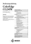
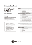
English
Deutsch
Important: Please read this Setup Manual and the User’s Manual stored on the
CD-ROM carefully to familiarize yourself with safe and effective usage.
Please retain this manual for future reference.
Français
Setup Manual
Installationshandbuch
Lesen Sie dieses Installationshandbuch und das Benutzerhandbuch (auf
der CD-ROM) aufmerksam durch, um sich mit der sicheren und effizienten Bedienung vertraut zu machen. Bewahren Sie dieses Handbuch zum
späteren Nachschlagen auf.
Manuel d’installation
Important : Veuillez lire attentivement ce manuel d’installation, ainsi que le manuel
d’utilisation inclus sur le CD-ROM, pour vous familiariser avec une utilisation
efficace et en toute sécurité. Veuillez conserver ce manuel pour référence
ultérieure.
设定手册
重要事项: 请仔细阅读储存在光盘片中的设定手册和用户手册,以便熟悉安全有效使
用本显示器的信息。请保留本手册,以便今后参考。
中文
Wichtig:
Compatible Resolutions/Frequencies
Kompatible Auflösungen/Bildwiederholfrequenzen
Résolutions/Fréquences compatibles
兼容的分辨率/频率
The monitor supports the following resolutions
Der Monitor unterstützt die nachfolgend aufgeführten Auflösungen
Le moniteur est compatible avec les résolutions suivantes.
本显示器支持下列分辨率。
Analog Input
Resolution
Display Mode
Frequency
640 × 480
640 × 480
720 × 400
800 × 600
832 × 624
1024 × 768
1152 × 864
1152 × 870
1280 × 960
1280 × 960
1280 × 1024
1600 × 1200
1680 × 1050*1
1920 × 1200 *1 *2
Apple Macintosh
VGA, VESA
VGA TEXT
VESA
Apple Macintosh
VESA
VESA
Apple Macintosh
VESA
Apple Macintosh
VESA
VESA
VESA CVT, VESA CVT RB
VESA CVT, VESA CVT RB
67 Hz
~85 Hz
70 Hz
~85 Hz
75 Hz
~85 Hz
75 Hz
75 Hz
60 Hz
75 Hz
~85 Hz
~75 Hz
60 Hz
60 Hz
Resolution
Display Mode
Frequency
640 × 480
720 × 400
800 × 600
1024 × 768
1280 × 960
1280 × 1024
1600 × 1200
1680 × 1050 *1
1920 × 1200*1 *2
VGA
VGA TEXT
VESA
VESA
VESA
VESA
VESA
VESA CVT, VESA CVT RB
VESA CVT RB
60 Hz
70 Hz
60 Hz
60 Hz
60 Hz
60 Hz
60 Hz
60 Hz
60 Hz
Dot Clock
202.5 MHz
(Max.)
Digital Input
*1
Dot Clock
164.5 MHz
(Max.)
When displaying the wide format input signal, a graphics board in conformance with VESA CVT standard is required.
*1
Zur Anzeige des Eingangssignals für das Breitbild ist eine Grafikkarte erforderlich, die die Anforderungen des Standards VESA CVT
erfüllt.
*1
Lors de l’affichage du signal d’entrée format large, une carte vidéo conforme à la norme VESA CVT est requise.
*1
当显示宽荧幕格式输入信号时,需要符合 VESA CVT 标准的显卡。
*2
Recommended resolusion (Set this resolution)
*2
Empfohlene Auflösung (diese Auflösung festlegen)
*2
Résolution recommandée (Réglez votre appareil sur cette résolution)
*2
推荐的分辨率 ( 设定此分辨率 )
SAFETY SYMBOLS
WARNING
Failure to abide by the information in a WARNING may result in serious injury and can be life
threatening.
CAUTION
Failure to abide by the information in a CAUTION
may result in moderate injury and/or property or
product damage.
Indicates a prohibited action.
Indicates a mandatory action that must be followed.
PRECAUTIONS
WARNING
If the unit begins to emit smoke, smells like
something is burning, or makes strange noises,
disconnect all power connections immediately
and contact your dealer for advice.
Attempting to use a malfunctioning unit may result
in fire, electric shock, or equipment damage.
Use the enclosed power cord and connect to
the standard power outlet of your country.
Be sure to remain within the rated voltage of the
power cord. Not doing so may result in fire or electric shock.
"Power Supply: 100-120/200-240 Vac 50/60Hz"
Keep small objects or liquids away from the
unit.
Small objects accidentally falling through the ventilation slots into the cabinet or spillage into the cabinet may result in fire, electric shock, or equipment
damage. If an object or liquid falls/spills into the
cabinet, unplug the unit immediately. Have the unit
checked by a qualified service engineer before using
it again.
Set the unit in an appropriate location.
Not doing so may result in fire, electric shock, or
equipment damage.
• Do not place outdoors.
• Do not place in the transportation system (ship,
aircraft, trains, automobiles, etc.).
• Do not place in a dusty or humid environment.
• Do not place in a location where the steam comes
directly on the screen.
• Do not place near heat generating devices or a
humidifier.
The equipment must be connected to a grounded main outlet.
Not doing so may result in fire or electric shock.
CAUTION
Do not block the ventilation slots on the cabinet.
• Do not place any objects on the ventilation slots.
• Do not install the unit in a closed space.
• Do not use the unit laid down or upside down.
Use an easily accessible power outlet.
This will ensure that you can disconnect the power
quickly in case of a problem.
Blocking the ventilation slots prevents proper airflow and may result in fire, electric shock, or equipment damage.
Do not carry the monitor with the hood
attached.
While carrying the monitor, the hood may fall or
slip off, which may result in injury or equipment
damage.
Do not place any objects on the hood.
If the hood falls or slips off or the monitor falls
over, it may result in injury or equipment damage.
Close the open/close cover until it contacts the
stopper.
If the cover is not closed properly, the ventilation
slots on the monitor will be covered and proper airflow will be prevented. This may cause overheatinginside the monitor and may result in fire, electric
shock, or equipment damage.
Do not rotate the monitor into the portrait
position.
Doing so may cause the hood to slip off, which may
result in injury or equipment damate.
1
English
This manual uses the safety symbols below. They denote critical information. Please read them carefully.
Package Contents
Check that all the following items are included in the packaging box. If any items are missing or damaged,
contact your local dealer.
NOTE
Please keep the packaging box and materials for future movement or transport of the monitor.
•
•
•
•
•
•
•
•
Monitor
Power cord
Digital signal cable (FD-C39)
Analog signal cable (FD-C16)
EIZO USB cable (MD-C93)
Hood
Mounting Screws (M4 x 12, 4 pcs)
Cleaning kit "ScreenCleaner"
• EIZO LCD Utility Disk (CD-ROM)
- Calibration software "ColorNavigator CE"
- Color Vision Deficiency simulation software "UniColor Pro"
- User’s Manual
• Setup Manual (this manual)
• ColorNavigator CE Quick Reference
• Limited warranty
• Recycling Information
• Adjustment Certificate
Controls and Functions
Adjustment menu
(ScreenManager ® *)
1
2
3
Detects ambient brightness. BrightRegulator function.
This function locks the buttons to retain the status adjusted or set once.
Switches input signals for display when two PCs are connected to the monitor.
4
5
Sensor
Adjustment Lock button
Input Signal Selection
button
Mode button
Auto button
6
Enter button
7
Control buttons
(Left, Down, Up, Right)
Power button
Power indicator
Displays the Adjustment menu, determines an item on the menu screen, and
saves values adjusted.
Chooses an adjustment item or increases/decreases adjusted values for advanced
adjustments using the Adjustment menu.
Turns the power on or off.
Indicates monitor’s operation status.
Blue: Operating Orange: Power saving Off: Power off
8
9
Allows you to switch the display mode.
Performs the function to adjust the screen automatically. (analog input only)
10
Security lock slot
Complies with Kensington’s MicroSaver security system.
11
Power connector
Connects the power connector.
12
Input signal connectors
DVI-I Connector x 2
13
USB port (Up)
14
USB port (Down)
Connects the USB cable in order to use the provided software. For how to use it,
refer to the User’s Manual on the CD-ROM.
Connects a peripheral USB device.
15
Stand
Used to adjust the height and angle of the monitor screen.
16
Cable holder
Covers the monitor cables.
* ScreenManager ® is an EIZO’s nickname of the Adjustment menu. (For how to use ScreenManager, refer to the User’s Manual on the CD-ROM.)
2
Connecting Cables
Check that the monitor and the PC are powered off.
English
USB cable
Power cord
1
Digital/Analog signal cable
Connect the monitor to the PC with a signal cable that matches the connectors.
After connecting the cable connectors, tighten the screws of the connectors to secure the coupling.
Connectors on the PC
cable
Connectors on the monitor
Signal cable FD-C16
�������
Signal cable FD-C39
�������
2
Connect the monitor to the PC with the USB cable.
Connecting to the Monitor
Connecting to a Computer
Note
• The USB cable is required for calibration. Be sure to connect the monitor and PC with the USB cable.
3
Plug the power cord into a power outlet and the power connector on the monitor.
4
Press
to turn on the monitor.
The monitor’s Power indicator lights up blue.
5
Turn on the PC.
The screen image appears.
If an image does not appear, refer to "No-Picture Problem" for additional advice.
Note
• Turn off the monitor and PC after using them. Unplugging the power cord completely shuts off
power supply to the monitor.
Adjusting the Screen Height and Angle
Adjust the screen height, tilt and swivel the screen to the best condition for working.
3
How to install the Hood
The Hood can reduce light reflection for on screen color consistency.
Package Contents
Check that all the following items are included in the packaging box.
Top cover
Open/close cover
Metal fitting
Left cover
Right Cover
Hook
Assemble the left and right hoods
Tips
• Assemble the hoods in the direction of the arrows marked on the insertions on the top covers of the right and
left hoods.
1
2
3
4
4
Hold the left hood’s left and top covers with the sides with the anti-reflective sheet
facing inward.
Connect the top and left covers by aligning the arrow (1 ) on the top cover’s
insertion with the two lines on the left cover’s insertion slot.
Slide the top cover in the direction shown by the arrow (2
Assembly of the left hood is complete.
Assemble the right hood in the same way.
).
Attach the left and right hoods to the monitor
Note
• Be sure to install the second hood only after the other hood is firmly attached with hook.
2
English
1
Attach the top side of the left hood to the monitor first and then securely fit the
left side of the hood in order to fix the hood to the monitor.
Insert the hook into the hole under the projection on the back side of the monitor
(1) and slide it down (2).
Insert into the hole
under projection
3
Attach the right hood in the same way.
4
Attach the left and right hoods to the monitor with the metal fitting.
5
Check the locations of the depressions in the fitting and insert the fitting into the
left and right hoods by aligning those depressions with the projections ( ) in the
grooves on the right and left hoods.
5
6
Attach the open/close cover to the left hood.
Note
• Do not attach the open/close cover to the right hood. Doing so prevents the cover from closing.
7
8
9
Place the open/close cover on the top of the left hood (without contacting the
metal fitting) from front (1) to back (2).
Slide the open/close cover to the right (3) until it contacts the stopper on the
metal fitting.
When performing calibration, slide the open/close cover to the right in order to
attach the sensor.
Note
• The open/close cover does not slide onto the right cover.
6
Prepare for the Monitor Calibration
Note
• For further details, refer to the User’s manual on the CD-ROM.
English
Installing ColorNavigator CE
1
Uninstall any measurement driver software that may be installed on the computer.
2
Insert the EIZO LCD Utility Disk into the computer’s CD/DVD drive.
3
4
Double-click on the CD-ROM icon on your desktop and then on the "Start
Menu" icon in the window. (Macintosh)
Click "Install ColorNavigator CE" in the EIZO LCD Utility’s initial screen.
Follow the instructions to complete the installation.
Note
• Measurement driver software is automatically installed during ColorNavigator CE installation. It is
not necessary to install the driver software that is supplied with your measurement device.
Connecting the measurement device
Connect your measurement device to the USB downstream port on your computeror keyboard, or the
USB port on your monitor.
Note
• The measurement device is not included in this product.
• Refer to the User’s Manual for the measurement device in regard to connection.
How to Calibrate the monitor
Start up ColorNavigator CE and follow the instructions.
Note
• Turn on both the monitor and the computer 30 minutes before calibration (warm up).
7
No-Picture Problem
If no picture is displayed on the monitor even after the following remedial action is taken,
contact your local dealer.
1. Check the Power indicator.
Symptom
No picture
Status
Power indicator does not light
up.
Possible cause and remedy
• Check whether the power cord is correctly
connected.
• Press .
Power indicator lights blue.
Check the gain* setting.
Power indicator lights orange.
Switch the input signal with
.
Press a key on the keyboard or click the mouse.
Turn on the PC.
* For detail of the gain adjustment, please refer to the User’s Manual on the CD-ROM.
2. Check the error message that remains on the screen.
These messages appear when the input signal is incorrect even if the monitor is functioning.
Symptom
Status
The input signal is not received.
Possible cause and remedy
Check whether the PC is turned on.
Check whether the signal cable is properly
connected to the PC.
Switch the input signal with
The signal frequency is outside
the specification. Incorrect
signal frequency is shown in
red.
8
.
Change the mode to an appropriate mode using
the graphics board’s utility software. Refer to the
manual of the graphics board for details.
SICHERHEITSSYMBOLE
In diesem Handbuch werden die unten dargestellten Sicherheitssymbole verwendet. Sie geben Hinweise auf äußerst wichtige
Informationen. Bitte lesen Sie diese Informationen sorgfältig durch.
VORSICHT
Die Nichtbefolgung von unter VORSICHT angegebenen Anweisungen kann schwere Verletzungen
oder sogar lebensbedrohende Situationen zur Folge
haben.
ACHTUNG
Die Nichbeachtung unter ACHTUNG angegebener
Informationen kann mittelschwere Verletzungen und/
oder Schäden oder Veränderungen des Produkts zur
Folge haben.
Weist auf eine unerlaubte Vorgehensweise hin.
Deutsch
Weist auf eine zwingend zu befolgende Vorgehensweise hin.
VORSICHTSMASSNAHMEN
VORSICHT
IWenn das Gerät Rauch entwickelt, verbrannt
riecht oder merkwürdige Geräusche produziert,
ziehen Sie sofort alle Netzkabel ab, und bitten
Sie Ihren Fachhändler um Rat.
Der Versuch, mit einem fehlerhaften Gerät zu arbeiten, kann Feuer, einen elektrischen Schlag oder eine
Beschädigung des Geräts verursachen.
Verwenden Sie zum Anschließen an die landesspezifische Standard-Netzspannung das
beiliegende Netzkabel.
Stellen Sie sicher, dass die Nennspannung des Netzkabels nicht überschritten wird. Andernfalls besteht
Brand- und Stromschlaggefahr.
„Stromversorgung: 100-120/200-240 Vac 50/60Hz“
Halten Sie Flüssigkeiten und kleine Gegenstände vom Gerät fern.
Flüssigkeiten oder kleine Gegenstände können aus
Versehen durch die Lüftungsschlitze in das Gehäuse
gelangen und somit Feuer, einen elektrischen Schlag
oder eine Beschädigung des Geräts verursachen.
Sollte ein Gegenstand oder eine Flüssigkeit in das
Gehäuse gelangt sein, ist sofort das Netzkabel des
Geräts abzuziehen. Lassen Sie das Gerät in diesem
Fall von einem qualifizierten Servicetechniker überprüfen, bevor Sie wieder damit arbeiten.
Stellen Sie das Gerät an einen geeigneten
Platz.
Andernfalls könnte das Gerät beschädigt werden,
und es besteht Brand- und Stromschlaggefahr.
• Verwenden Sie das Gerät nicht im Freien.
• Geben Sie das Gerät nicht als Transportgut auf
(per Schiff, Flugzeug, Zug, Auto etc.).
• Installieren Sie es nicht in staubiger oder feuchter
Umgebung.
• Stellen Sie es nicht an einen Platz, an dem Licht
direkt auf den Bildschirm fällt.
• Stellen Sie es nicht in die Nähe eines Wärme
erzeugenden Geräts oder eines Luftbefeuchters.
Das Gerät muss an eine ordnungsgemäß geerdete Steckdose angeschlossen werden.
Andernfalls besteht Brand- und Stromschlaggefahr.
ACHTUNG
Blockieren Sie die Lüftungsschlitze am Gehäuse nicht.
• Legen Sie keine Objekte auf die Lüftungsschlitze.
• Installieren Sie das Gerät nicht in einem engen
Raum.
• Setzen Sie das Gerät nur in der korrekten Orientierung
ein.
Das Blockieren der Lüftungsschlitze führt dazu, dass
die Luft nicht mehr zirkulieren und somit Feuer,
ein elektrischer Schlag oder eine Beschädigung des
Geräts verursacht werden kann.
Schließen Sie das Netzkabel an eine leicht
zugängliche Steckdose an.
Damit stellen Sie sicher, dass Sie das Netzkabel im
Notfall schnell abziehen können.
Tragen Sie den Monitor nicht mit angebrachter
Haube.
Beim Tragen des Monitors könnte die Haube
abfallen oder vom Gerät rutschen, wodurch es zu
Verletzungen oder einer Beschädigung des Geräts
kommen könnte.
Stellen Sie keine Gegenstände auf die Haube.
Falls die Haube abfällt oder vom Gerät rutscht oder
falls der Monitor umkippt, kann es zu Verletzungen
oder einer Beschädigung des Geräts kommen.
Schließen Sie die Abdeckung zum Öffnen/
Schließen, bis sie den Anschlag berührt.
Falls die Abdeckung nicht richtig geschlossen wird,
sind die Lüftungsschlitze abgedeckt, und der richtige Luftfluss wird verhindert. Dadurch kann es
zu Überhitzen im Monitor kommen, was zu einem
Brand, Stromschlag oder einer Beschädigung des
Geräts führen kann..
Drehen Sie den Monitor nicht in die Hochformat-Position.
Anderenfalls könnte die Haube vom Gerät rutschen,
wodurch es zu Verletzungen oder einer Beschädigung des Geräts kommen könnte.
1
Lieferumfang
Prüfen Sie, ob sich alle der folgenden Gegenstände in der Verpackung befinden. Sollte einer der Gegenstände
fehlen oder beschädigt sein, wenden Sie sich an Ihren Fachhändler.
HINWEIS
Heben Sie die Verpackung sowie die Verpackungsmaterialien für evtl. Transporte des Monitors gut auf.
•
•
•
•
•
•
•
•
Monitor
Netzkabel
Digitales Signalkabel (FD-C39)
Analoges Signalkabel (FD-C16)
EIZO USB-Kabel (MD-C93)
Abdeckhaube
Befestigungsschrauben (M4 x 12, 4 Stck.)
Reinigungsset „ScreenCleaner“
• CD-ROM mit EIZOs LCD Utility Disk)
- Kalibirierungssoftware „ColorNavigator CE“
- Color Vision Deficiency Simulation Software „UniColor Pro“
- Benutzerhandbuch
• Installationshandbuch (das vorliegende Handbuch)
• ColorNavigator CE-Kurzanleitung
• Beschränkte Garantie
• Informationen zum Thema Recycling
• Justagezertifizierung
Bedienelemente und Funktionen
Justierungsmenü
(ScreenManager ® *)
1
Sensor
Erkennt die Umgebungshelligkeit. Funktion zur Helligkeitsregulierung.
2
Taste zur Justiersperre
3
Taste zur Auswahl des
Eingangssignals
Mit dieser Funktion werden die Tasten zum Beibehalten des justierten
oder eingestellten Status gesperrt.
Schaltet zwischen den Signalen zweier angeschlossener Computer um.
4
Taste zur Modusauswahl
Mithilfe dieser Taste wechseln Sie den Anzeigemodus.
5
Taste zur automatischen Einstellung
6
Eingabetaste
7
Steuertasten (Links, Unten, Oben,
Rechts)
Netzschalter
Betriebsanzeige
Performs the function to adjust the screen automatically.
(analog input only)
Zeigt das Justierungsmenü an, wählt ein Element im Menübildschirm
und speichert geänderte Werte.
Wählt ein Einstellungselement oder erhöht/reduziert justierte Werte
erweiterter Einstellungen mithilfe des Justierungsmenüs.
Zum Ein- und Ausschalten.
Zeigt den Betriebsstatus des Monitors an.
Blau: In Betrieb Orange: Energiesparmodus
Aus: Hauptstromversorgung getrennt
Kompatibel mit dem Kensington MicroSaver-Sicherheitssystem.
8
9
10
11
12
13
Öffnung für
Diebstahlsicherung
Netzstecker
Signaleingänge
USB-Anschluss (hinten)
14
USB-Anschluss (seitlich)
Zum Anschließen an eine Netzsteckdose.
DVI-I-Anschluss x 2
Anschluss des USB-Kabels bei der Verwendung von ScreenManager
Pro für LCD-Software (für Windows). Informationen zur Verwendung der
Software entnehmen Sie der Benutzerhandbuch auf der CD-ROM.
Stellt eine Verbindung zu einem USB-Peripheriegerät her.
15
Fuß
Zum Einstellen der Höhe und Neigung des Bildschirms.
16
Kabelabdeckung
®
Verdeckt die Anschlusskabel.
* ScreenManager ist der Name des Justierungsmenüs von EIZO. (Informationen zur Verwendung von ScreenManager entnehmen Sie dem
Benutzerhandbuch auf der CD-ROM.)
2
Kabel anschließen
Stellen Sie sicher, dass Computer und Monitor ausgeschaltet sind.
USB-Kabel
Netzkabel
Verbinden Sie Monitor und Computer mithilfe eines passenden Signalkabels.
Deutsch
1
Digitales/Analoges Signalkabel
Ziehen Sie nach dem Anschließen der Kabel die Schrauben der Verbinder an, um ein versehentliches Ausstecken zu verhindern.
Anschlüsse am PC
kabel
Anschlüsse am Monitor
Signalkabel FD-C16
�������
Signalkabel FD-C39
�������
2
Schließen Sie das USB-Kabel an, um die mitgelieferte Software verwenden zu können.
Anschließen an den Monitor
Anschließen an einen Computer
Hinweis
• Das USB-Kabel ist für die Kalibrierung erforderlich. Verbinden Sie Monitor und PC mit dem USB-Kabel.
3
4
Verbinden sie mithilfe des Netzkabels den Netzanschluss des Monitors mit einerSteckdose.
Drücken Sie
, um den Monitor einzuschalten.
Die Betriebsanzeige des Monitors leuchtet auf (blau).
5
Schalten Sie den Computer ein.
Schalten Sie den Computer ein.
Wenn kein Bild erscheint, ermitteln Sie mit Hilfe des Kapitels „Problem: Kein Bild” die Ursache
dieses Problems.
Hinweis
• Schalten Sie Computer und Monitor aus, wenn Sie sie nicht mehr benötigen. Wenn Sie das
Netzkabel abziehen, wird die Stromzufuhr zum Monitor vollständig unterbrochen.
Höhe und Neigung des Bildschirms einstellen
Stellen Sie die für Ihren Arbeitsplatz optimale Höhe, Neigung und Drehung des Bildschirms ein.
3
Installation der Haube
Der Blendschutz ist dazu gedacht, zur Erzielung einer besseren Farbkonsistenz Lichtreflektionen zu
vermindern.
Lieferumfang
Prüfen Sie, ob sich alle der folgenden Gegenstände in der Verpackung befinden.
Obere Abdeckung
Abdeckung zum Öffnen/Schließen
Metallverbindungsstück
Linke Abdeckung
Rechte Abdeckung
Haken
Montage der linken und rechten Haube
Hinweis
• Montieren Sie die Hauben in Richtung der Pfeile, die auf den Einfügungsteilen der oberen Abdeckungen der
rechten und linken Haube markiert sind.
1
2
3
4
4
Halten Sie die linke und obere Abdeckung der linken Haube so, dass die Antireflexionsbeschichtung nach innen zeigt.
Schließen Sie die obere und linke Abdeckung an, indem Sie den Pfeil (1 ) auf
dem Einfügungsteil der oberen Abdeckung auf die beiden Striche im Einfügungsschlitz der linken Abdeckung ausrichten.
Schieben Sie die obere Abdeckung in die von Pfeil (2
Montage der linken Haube ist abgeschlossen.
Montieren Sie die rechte Haube auf die gleiche Weise.
) angezeigte Richtung. Die
Befestigen Sie die linke und die rechte Haube am Monitor.
Hinweis
• Achten Sie darauf, die zweite Haube erst zu installieren, nachdem Sie die andere Haube sicher mit einem
Haken angebracht haben..
1
Befestigen Sie die Oberseite der linken Haube zuerst am Monitor, und befestigen
Sie dann die linke Seite der Haube sicher, um die Haube am Monitor anzubringen.
Deutsch
2
Führen Sie den Haken in das Loch unter dem Vorsprung auf der Rückseite des
Monitors (1) ein, und schieben Sie ihn nach unten (2).
In das Loch unter dem
Vorsprung einführen
3
4
5
Befestigen Sie die rechte Haube auf die gleiche Weise.
Befestigen Sie die linke und die rechte Haube mit den Metallverbindungsstücken
am Monitor.
Überprüfen Sie die Stellen mit den Vertiefuungen an den Verbindungsstücken, und
führen Sie die Verbindungsstücke in die rechte und linke Haube ein, indem Sie
jene Vertiefungen auf die Vorsprünge ( ) in den Nuten der rechten und linken
Haube ausrichten.
5
6
Befestigen Sie die Abdeckung zum Öffnen/Schließen an der linken Haube.
Hinweis
• Befestigen Sie die Abdeckung zum Öffnen/Schließen nicht an der rechten Haube. Anderenfalls
kann die Abdeckung nicht geschlossen werden.
7
8
9
Setzen Sie die Abdeckung zum Öffnen/Schließen auf die Oberseite der linken
Haube (ohne das Metallverbindungsstück zu berühren), und zwar von vorne (1)
nach hinten (2).
Schieben Sie die Abdeckung zum Öffnen/Schließen nach rechts (3), bis sie den
Anschlag am Metallverbindungsstück berührt.
Schieben Sie die Abdeckung zum Öffnen/Schließen bei der Durchführung der
Kalibrierung nach rechts, um den Sensor anzubringen.
Hinweis
•Die Abdeckung zum Öffnen/Schließen kann nicht auf die rechte Abdeckung geschoben werden.
6
Vorbereitung für die Kalibrierung des Monitors
Hinweis
• Weitere Einzelheiten finden Sie im Benutzerhandbuch auf der CD-ROM.
Installation von ColorNavigator CE
4
Deinstallieren Sie alle Messtreiber, die auf Ihrem Computer installiert sind.
Legen Sie die EIZO LCD Dienstprogramm-Disk in das CD/DVD-Laufwerk ein.
Deutsch
1
2
3
Doppelklicken Sie auf des CD-ROM-Symbol auf Ihrem Desktop, und dann auf
das Symbol „Start Menu”, das im Fenster angezeigt wird. (Macintosh)
Klicken Sie auf „Install ColorNavigator CE” im Anfangsbildschirm des EIZO
LCD-Dienstprogramms.
Befolgen Sie die Anleitungen, um die Instalaltion abzuschließen.
Hinweis
• Der Messtreibre wird während der ColorNavigator CE-Installation automatisch installiert. Es ist nicht
erforderlich, den mit Ihrem Messgerät mitgelieferten Treiber zu installieren.
Anschließen des Messgeräts
Schließen Sie Ihr Messgerät an einem USB-Downstream-Port Ihres Computers oder Ihrer Tastatur bzw.
am USB-Port Ihres Monitors an.
Hinweis
• Das Messgerät ist nicht im Lieferumfang dieses Produkts enthalten.
• Zusätzliche Hinweise zum Anschluss finden Sie im Benutzerhandbuch des Messgeräts.
Kalibrierung des Monitors
Starten Sie ColorNavigator CE, und befolgen Sie die angezeigten Anleitungen.
Hinweis
• Schalten Sie sowohl den Monitor als auch den Computer 30 Minuten vor Beginn der
Kalibrierung ein (Warmlauf).
7
Problem: Kein Bild
Wird auch nach dem Durchführen der nachfolgend vorgeschlagenen Lösungen kein Bild
angezeigt, wenden Sie sich an Ihren Fachhändler.
1. Prüfen Sie den Status der Betriebsanzeige.
Symptom
Kein Bild
Status
Mögl. Ursache und Lösung
Anzeigenstatus: Aus.
• Prüfen Sie, ob das Netzkabel richtig
eingesteckt ist.
• Drücken Sie .
Anzeigenstatus: Blau
Überprüfen Sie die Gain* -Einstellung.
Betriebsanzeigenstatus: Orange
Wechseln Sie durch Drücken der Taste
Signaleingang.
den
Drücken Sie eine Taste auf der Tastatur, oder
klicken Sie mit der Maus.
Schalten Sie den Computer ein.
* Weitere Einzelheiten zur Gain-Einstellung entnehmen Sie dem Benutzerhandbuch auf der CD-ROM.
2. Überprüfen Sie die Fehlermeldung auf dem Bildschirm.
Diese Meldungen werden angezeigt, wenn das Eingangssignal nicht ordnungsgemäß übertragen wird, der
Monitor jedoch korrekt funktioniert.
Symptom
Status
Das Eingangsignal wird nicht
empfangen.
Mögl. Ursache und Lösung
Prüfen Sie, ob der Computer eingeschaltet ist.
Prüfen Sie, ob das Signalkabel ordnungsgemäß
am Computer angeschlossen ist.
Wechseln Sie durch Drücken der Taste
Signaleingang.
Die Signalfrequenz liegt nicht im
zulässigen Bereich. Die falsche
Signalfrequenz wir rot angezeigt.
8
den
Wechseln Sie mithilfe des zur Grafikkarte
gehörenden Dienstprogramms in einen
kompatiblen Modus. Weitere Informationen
hierzu entnehmen Sie dem Handbuch der
Grafikkarte.
�
SYMBOLES DE SECURITE
Ce manuel utilise les symboles de sécurité présentés ci-dessous. Ils signalent des informations critiques. Veuillez les lire attentivement.
AVERTISSEMENT
Le non respect des consignes données dans un
message AVERTISSEMENT peut entraîner des
blessures sérieuses ou même la mort.
ATTENTION
Le non respect des consignes données dans un
message ATTENTION peut entraîner des blessures
et/ou des dommages au matériel ou au produit.
Indique une action interdite.
Indique une action obligatoireà suivre.
PRECAUTIONS
AVERTISSEMENT
Utilisez le cordon secteur fourni pour le
branchement sur la prise secteur standard
dans votre pays.
Vérifiez la tension d’épreuve du cordon secteur.
Tout autre branchement peut présenter des risques
d’incendie ou de choc électrique.
« Alimentation : 100-120/200-240 Vca 50/60 Hz »
Eloignez les petits objets ou les liquides de
l’appareil.
L’introduction accidentelle de petits objets ou de
liquide dans les fentes de ventilation de la carrosserie peut entraîner un choc électrique, un incendie
ou des dégâts à l’appareil. Si un objet tombe dans
la carrosserie ou si du liquide se répand sur ou à l’
intérieur de l’appareil, débranchez immédiatement
le cordon secteur. Faites contrôler l’appareil par un
technicien qualifié avant de l’utiliser à nouveau.
Choisissez bien l’emplacement du moniteur.
Il y a des risques de dégâts à l’appareil, d’incendie
ou de choc électrique.
• Ne pas utiliser à l’extérieur.
• Ne pas utiliser dans des moyens de transport
(bateau, avion, trains, automobiles, etc.).
• Ne pas installer l’appareil dans un environnement
poussiéreux ou humide.
• Ne pas installer l’appareil à un endroit exposé
directement à la vapeur d’eau.
• Ne pas placer l’appareil près des appareils de
chauffage ou d’humidification.
L’appareil doit être relié à une prise avec terre.
Tout autre branchement peut présenter des risques d’incendie ou de choc électrique.
ATTENTION
N’obstruez pas les fentes de ventilation de la
carrosserie.
• Ne placez jamais d’objets sur les fentes de
ventilation.
• N’installez pas le moniteur dans un espace
confiné.
• N’utilisez pas le moniteur couché sur le côté ni à
l’envers.
Toutes ces utilisations risquent d’obstruer les fentes de ventilation et d’empêcher une circulation d’
air normale, et d’entraîner un incendie ou d’autres
dégâts.
Utilisez une prise électrique facilement accessible.
Ceci vous permettra de débrancher rapidement
l’appareil en cas de problème.
Ne transportez pas le moniteur avec son capot.
Lorsque vous transportez le moniteur, le capot peut
tomber ou glisser et entraîner ainsi des blessures ou
endommager l’appareil.
Ne placez aucun objet sur le capot.
Si le capot tombe ou glisse ou que le moniteur
tombe, cela peut entraîner des blessures ou
endommager l’appareil.
Refermez le panneau d’ouverture/fermeture
jusqu’à ce qu’il touche le taquet d’arrêt.
Si le panneau n’est pas refermé correctement, les
fentes de ventilation du moniteur seront obstruées
et la circulation d’air ne se fera pas correctement.
Cela peut provoquer une surchauffe à l’intérieur
du moniteur pouvant entraîner des incendies, chocs
électriques et dégâts de l’appareil.
Ne faites pas pivoter le moniteur en position
portrait.
Cela pourrait faire glisser le capot et entraîner des
blessures ou endommager l’appareil
1
Français
Si le moniteur fume, sent le brûlé ou émet des
bruits anormaux, débranchez immédiatement
tous les cordons secteur et prenez contact
avec votre revendeur.
Il peut être dangereux d’utiliser un moniteur au
fonctionnement défectueux.
Contenu de l’emballage
Vérifiez que tous les éléments indiqués ci-dessous sont inclus dans le carton d’emballage. Contactez votre
revendeur local si l’un des éléments est manquant ou abîmé.
REMARQUE
Veuillez conserver le carton et les matériaux d’emballage pour les réutiliser lors d’un déplacement ultérieur du
moniteur.
•
•
•
•
•
•
•
•
Moniteur
Cordon d’alimentation
Câble de signal numérique (FD-C39)
Câble de signal analogique (FD-C16)
Câble EIZO USB (MD-C93)
Capot
Vis de montage (M4 x 12, 4 pièces)
Kit de nettoyage « ScreenCleaner »
• EIZO LCD Utility Disk (CD-ROM)
- Logiciel d'étalonnage "ColorNavigator CE"
- Logiciel de simulation Color Vision Defiency "UniColor Pro"
- Manuel d’utilisation
• Manuel d’installation (ce manuel)
• Référence rapide de ColorNavigator CE
• Garantie limitée
• Informations sur le recyclage
• Certification du réglage
Commandes et fonctions
Menu Ajustage
(ScreenManager ® *)
1
2
3
4
5
6
7
8
9
10
Capteur
Touche de Verrouillage des
réglages
Touche de sélection du
signal d’entrée
Touche Mode
Touche de réglage Auto
Touche de validation
Touches de commande
(Gauche, Bas, Haut, Droite)
Touche d’alimentation
Voyant d’alimentation
13
Fente pour le verrouillage
de sécurité
Connecteur d’alimentation
Connecteurs de signal
d’entrée
Port USB (amont)
14
15
16
Port USB (aval)
Pied
Enveloppe de câbles
11
12
Détecte la luminosité ambiante. Fonction BrightRegulator.
Cette fonction verrouille les touches pour maintenir l’état réglé ou défi ni
précédemment.
Pour commuter les signaux d’entrée de l’affichage lors de la connexion de 2 PC
au moniteur.
Permet de changer le mode d’affichage.
Pour ajuster automatiquement l’écran. (entrée analogique uniquement)
Pour afficher le menu Ajustage, pour sélectionner un élément de l’écran de
menu et sauvegarder les valeurs ajustées.
Pour sélectionner un élément d’ajustage ou augmenter/diminuer les valeurs
ajustées pour des ajustages avancés à l’aide du menu Ajustage.
Pour mettre sous/hors tension.
Pour indiquer l’état de fonctionnement du moniteur.
Bleu : En fonctionnement Orange : Economie d’énergie Eteint : Hors tension
Compatible avec le système de sécurité MicroSaver de Kensington.
Permet de raccorder le connecteur d’alimentation.
Connecteur DVI-I x 2
Raccorde le câble USB pour utiliser le logiciel fourni. Consultez le manuel d’
utilisation inclus sur le CD-ROM pour savoir comment utiliser ce logiciel.
Permet de raccorder un périphérique USB.
Utilisé pour ajuster la hauteur et l’angle de l’écran du moniteur.
Protège les câbles du moniteur.
* ScreenManager ® est un alias choisi par EIZO pour le menu Ajustage. (Consultez le manuel d’utilisation sur le CD-ROM si vous désirez de plus amples
détails sur l’utilisation de ScreenManager.)
2
Connexion des câbles
Vérifiez que le moniteur et le PC sont hors tension.
Câble USB
Cordon d’alimentation
1
Câble de signal numérique/analogique
Connectez le moniteur au PC à l’aide d’un câble de signal correspondant aux connecteurs.
Une fois que les connecteurs de câble sont connectés, serrez les vis des connecteurs pour assurer le
couplage.
Connecteurs de l’ordinateur
Câble
Connecteurs du moniteur
Câble de signal FD-C16
�������
Câble de signal FD-C39
�������
Français
2
Raccordez le moniteur à l’ordinateur avec le câble USB.
Connexion au moniteur
Connexion à un ordinateur
Attention
• Le câble USB est nécessaire pour le calibrage. Veillez à raccorder le moniteur et l’ordinateur avec le
câble USB.
3
4
Branchez le cordon d’alimentation dans une prise secteur et dans le connecteur
d’alimentation du moniteur.
Appuyez sur
pour mettre le moniteur sous tension.
Le voyant d’alimentation du moniteur s’éclaire en bleu.
5
Mettez le PC sous tension.
L’image affichée apparaît. Si une image n’apparaît pas, consultez la sectio « Problème de nonaffichage d’images » fpour savoir commentprocéder.
Attention
• Mettez le moniteur et le PC hors tension lorsque vous ne les utilisez plus. L’alimentation du
moniteur est coupée en débranchant le cordon d’alimentation.
Ajustage de la hauteur et de l’angle de l’écran
Pour permettre d’ajuster la hauteur, l’inclinaison et l’orientation de l’écran à une position agréable pour
le travail.
3
Installation du capot
Le capot peut réduire les reflets pour assurer la précision du rendu des couleurs.
Contenu de l’emballage
Vérifiez que tous les éléments indiqués ci-dessous sont inclus dans le carton d’emballage.
Panneau d’ouverture/fermeture
panneau supérieur
Pièce en métal
panneau gauche
panneau droit
Crochet
Montez le capot gauche et le capot droit
Remarque
• Montez les capots dans la direction des flèches indiquées sur les insertions des panneaux supérieurs des capots
gauche et droit.
1
2
3
4
4
Tenez les panneaux gauche et supérieur du capot gauche de façon à ce que le film
antireflet soit à l’intérieur.
Raccordez le panneau supérieur et le panneau gauche en alignant la flèche
(1 ) de l’insertion du panneau supérieur sur les deux lignes de la fente d’insertion du panneau gauche.
Faites glisser le panneau supérieur dans la direction de la flèche (2
Le montage du capot gauche est terminé.
Montez le capot droit de la même manière.
).
Fixez les capots gauche et droit sur le moniteur.
Attention
• Veillez à installer le second capot uniquement après avoir fermement fixé le premier capot avec le crochet.
1
2
Fixez d’abord le haut du capot gauche sur le moniteur, puis attachez correctement
le côté gauche du capot afin de fixer le capot sur le moniteur.
Insérez dans l’orifice
sous la saillie.
3
4
5
Fixez le capot droit de la même manière.
Fixez les capots gauche et droit sur le moniteur avec la pièce en métal.
Vérifiez l’emplacement des creux dans la pièce et insérez la pièce dans les capots
gauche et droit en alignant ces creux sur les saillies ( ) dans les rainures des capots gauche et droit.
5
Français
Insérez le crochet dans l’orifice sous la saillie à l’arrière du moniteur (1) et faites-le
glisser vers le bas (2).
6
Fixez le panneau d’ouverture/fermeture sur le capot gauche.
Attention
• Ne fixez pas le panneau d’ouverture/fermeture sur le capot droit. Cela empêcherait le panneau
de se fermer.
7
8
9
Placez le panneau d’ouverture/fermeture sur le haut du capot gauche (sans entrer
en contact avec la pièce de métal) de l’avant (1) vers l’arrière (2).
Faites glisser le panneau d’ouverture/fermeture vers la droite (3) jusqu’à ce qu’il
touche le taquet d’arrêt sur la pièce de métal.
Lors de l’exécution du calibrage, faites glisser le panneau d’ouverture/fermeture
vers la droite afin de fixer le capteur.
Attention
• Le panneau d’ouverture/fermeture ne glisse pas sur le panneau gauche.
6
Préparez le moniteur pour le calibrage
Attention
• Pour plus de détails, consultez le manuel d’utilisation sur le CD-ROM.
Installer ColorNavigator CE
1
2
3
4
Désinstallez tout pilote de mesurage installé sur l’ordinateur.
Insérez le disque d’utilitaires EIZO LCD dans le lecteur de CD/DVD de
l’ordinateur.
Cliquez deux fois sur l’icône du CD-ROM sur votre bureau puis sur l’icône
« Start Menu » dans la fenêtre. (Macintosh)
Cliquez sur « Install ColorNavigator CE » dans l’écran initial des utilitaires EIZO
LCD.
Attention
• Le pilote de mesure est automatiquement installé pendant l’installation de ColorNavigator CE. Il n’est
pas nécessaire d’installer le pilote fourni avec votre appareil de mesure.
Raccordement de l’appareil de mesure
Raccordez votre appareil de mesure au port USB en amont de votre ordinateur ou au port USB de votre
moniteur.
Attention
• L’appareil de mesure n’est pas inclus avec ce produit.
• Consultez le manuel d’utilisation de l’appareil de mesure pour plus de détails concernant le
raccordement.
Calibrer le moniteur
Lancez ColorNavigator�CE et suivez les instructions.
Attention
• Allumez le moniteur et l’ordinateur 30 minutes avant le calibrage (préchauffage).
7
Français
Suivez les instructions pour terminer l’installation.
Problème de non-affichage d’images
Si aucune image ne s’affiche sur le moniteur même après avoir utilisé les solutions suivantes,
contactez votre revendeur local.
1. Vérifiez le voyant d’alimentation.
Symptôme
Aucune image
Etat
Le voyant ne s’allume pas.
Cause possible et solution
• Le voyant s’allume en bleu.
• Press .
Le voyant s’allume en bleu.
Check the gain* setting.
Le voyant d’alimentation
s’allume en orange.
Changez le signal d’entrée en appuyant sur
.
Appuyez sur une touche du clavier ou cliquez
avec la souris.
Mettez le PC sous tension.
* Consultez le Manuel d’utilisation inclus sur le CD-ROM pour plus de détails sur le réglage de gain.
2. Vérifiez le message d’erreur qui apparaît à l’écran.
Ces messages s’affichent lorsque le signal d’entrée est incorrect même si le moniteur fonctionne correctement.
Symptôme
Etat
Le signal d’entrée n’est pas
reçu.
Cause possible et solution
Vérifiez si le PC est sous tension.
Vérifiez si le câble de signal est correctement
connecté au PC.
Changez le signal d’entrée en appuyant sur
La fréquence du signal est en
dehors de la spécification. La
fréquence de signal incorrecte
est indiquée en rouge.
8
Passez en un mode approprié à l’aide du
logiciel utilitaire de la carte vidéo. Consultez le
manuel de la carte vidéo pour de plus amples
détails.
.
色彩管理液晶显示器
�
安全符号
本手册使用的安全符号如下。它们表示重要信息。请仔细阅读。
警告
若不遵守“警告”中的信息,可能会造成严重伤害
或威胁到生命安全。
注意
若不遵守“注意”中的信息,可能会造成中度伤害
并/或使财产或产品受损。
表示禁止的动作。
表示必须遵照执行的命令动作。
预防措施
警告
若机器出现烟雾,闻起来像是东西着火,或者有奇
怪声音,请立刻断开所有电源,并联络经销商以寻
求建议。
尝试使用功能异常的机器可能会造成火灾、电击或
设备受损。
使用内附电源线,并连接当地的标准电源插座。
确保电源电压在电源线的额定电压范围内。否则可
能会造成火灾或电击。
“电源:100-120/200-240 V AC 50/60Hz”
让机器远离小物品或液体。
在适当的位置安装机器。
小物品意外掉入通风槽而进入机壳,或液体溢入机
壳会造成火灾、电击或设备受损。若物品掉入或液
体溢入机壳,请立刻拔下机器的电源插头。再次使
用机器前,请由合格的服务工程师检查。
否则可能会造成火灾、电击或设备受损。
中文
• 请勿放于户外。
• 请勿放于交通运输系统中(轮船、飞机、火车、
汽车等)。
• 请勿放于布满灰尘或潮湿的环境中。
• 请勿放于蒸气直接达到屏幕的地方。
• 请勿放于热源装置或加湿器附近。
装置必须连接到接地主插座。
否则可能会造成火灾或电击。
注意
请勿阻塞机壳上的通风槽。
使用可轻易连接的电源插座。
• 请勿将任何物品放于通风槽上。
• 请勿将机器安装在封闭空间中。
• 请勿在机器放下或颠倒时使用。
这可确保问题发生时快速断开电源。
阻塞通风槽会阻碍适当气流进出,并造成火灾、电
击或设备受损。
请勿在安装了遮光板的状态下移动显示器。
请勿在遮光板上放置物品。
在移动中可能会发生遮光板的脱落导致人员伤害或
设备损坏。
可能会发生遮光板的坠落或显示器的翻倒,导致人
员伤害或设备损坏。
请将遮光板的开合板闭合至碰到挡块的位置。
请勿竖起显示器。
如果没有充分闭合,会堵塞显示器上的通风孔,妨
碍正常的空气流通。可能会因此造成显示器内部高
温,导致火灾、触电和故障等事故。
可能会发生遮光板的脱落,导致人员伤害或设备损
坏。
1
包装内容
请检查包装盒中是否包含下列物品。如果缺少物品,或物品存在损坏现象,请与您所在地的经销商联系。
注意
请保留好包装盒和包装材料,以便将来显示器移动或搬运时使用。
•
•
•
•
•
•
•
•
显示器
电源线
数字信号电缆 (FD-C39)
模拟信号电缆 (FD-C16)
EIZO USB电缆 (MD-C93)
遮光板
安装螺丝 (M4 x 12, 4 pcs)
清洗套餐“ScreenCleaner”
• EIZO LCD Utility Disk(光盘)
- 测定软件“ColorNavigator CE(颜色扫描)”
(光盘内)
- Color Vision Deficiency模拟软件“UniColor Pro”
- 用户手册
• 设定手册(本手册)
• ColorNavigator CE 快速参考
• 有限责任保证书
• 调节认证
控制和功能
调整菜单
(ScreenManager ® *)
1
2
3
4
5
6
7
8
9
*
2
传感器
调整锁定按钮
输入信号选择按钮
模式按钮
自动调节按钮
确认按钮
控制按钮(左、下、上、右)
电源按钮
电源指示器
探测周围亮度。BrightRegulator 功能。
此功能可锁定按钮以保持调整后的状态或设定后的状态。
当两个个人计算机连接在显示器上时,可用此按钮切换显示的输入信号。
可切换显示模式。
自动调节屏幕到合适状态。(仅限模拟输入)
显示调整菜单,确定菜单屏幕上的某个项目,并保存已调整的值。.
选择调整项目,或增加/降低利用调整菜单进行高级调整时的已调整值。
打开或关闭电源。
指示显示器的运行状态。
蓝色:运行中 橙色:省电状态 熄灭:电源关闭
10
安全锁插槽
符合 Kensington 的防盗锁安全系统。
11
电源连接器
连接电源连接器。
12
输入信号连接器
DVI-I 连接器 x 2
13
USB 端口(上)
使用软件时,用 USB 电缆连接。关于如何使用此软件,请参考光盘上的用户手册。
14
USB 端口(下)
连接外接 USB 设备。
15
底座
用于调整显示器屏幕的高度和角度。
16
电缆固定器
固定显示器电缆。
ScreenManager® 是调整菜单的 EIZO 别称。(关于如何使用 ScreenManager,请参考光盘中的用户手册。)
连接电缆
确保显示器和个人计算机的电源关闭。
USB 电缆
电源线
1
数字信号电缆/模拟信号电缆
用一根与连接器匹配的信号电缆连接显示器和个人计算机。
连接到电缆连接器后,请拧紧连接器的螺钉,使配合紧密。
个人计算机上的连接器
电缆
显示器上的连接器
信号电缆 FD-C16
�������
信号电缆 FD-C39
�������
2
使用 USB 电缆连接显示器和计算机。
接续到显示器
接续到计算机
注意
• 进行校准时需要 USB 电缆。请务必使用 USB 电缆连接。
将电源线插头插入电源插座和显示器上的电源连接器。
4
按
中文
3
打开显示器。
显示器电源指示器亮起蓝色。
5
将个人计算机开机。
屏幕图像出现。
如果无法出现图像,请参考“无图片的问题”以获得帮助。
注意
• 使用后关闭显示器和个人计算机。拔下电源插头可完全关闭显示器的电源。
调整屏幕高度和角度
调整屏幕高度,并将屏幕倾斜和旋转到最佳工作位置。
3
遮光板的安装
遮光板可以降低光线的反射,更好的保持屏幕色彩一致性。
包装内容
请检查包装盒中是否包含下列物品。如果缺少物品,或物品存在损坏现象,请与您所在地的经销商联系。
开合板
顶板
固定用金属零件
左侧板
右侧板
固定钩
左右遮光板的组装
注意
• 请按照左右遮光板(顶板)嵌入部分指示的箭头方向进行组装
4
1
握住左侧遮光板的左侧板及顶板,使贴有防反射膜的一面向内。
2
将顶板嵌入部分箭头 (1
3
顶板沿着箭头 (2
). 方向滑动。
左遮光板组装完成。
4
右遮光板按照相同的方法进行组装。
) 的位置对准左侧板的嵌入槽(双线记号),垂直嵌入。
将左右遮光板安装在显示器上
注意
• 请在将一侧的遮光板用固定钩确实固定后,再安装另外一侧的遮光板。
1
左遮光板从显示器的上部开始安装,然后从侧面确实嵌入左侧板,以便将遮光板
固定在显示器上。
2
将固定钩嵌入显示器背面的突出部分下侧的孔(1),并向下滑动(2)。
嵌入下侧的孔
中文
3
右遮光板按照相同的方法安装。
4
安装固定用金属零件,将左右遮光板固定在显示器上。
5
确认固定用金属零件凹槽的位置,将固定用金属零件的凹槽对准左右遮光板槽的
突出部分 ( 的位置 ) 并嵌入。
5
6
将开合板安装在左遮光板上。
注意
• 如果将开合板安装在右遮光板上,开合板将无法闭合。
7
按照从前 ( 1 ) 到后 ( 2 ) 的顺序将开合板覆盖在左遮光板上部(无固定用金属
件的部分)。
8
将开合板向右滑动闭合 ( 3 ),直到碰到固定用金属件的挡块。
9
进行校准时,将开合板滑动到右侧,安装传感器。
注意
• 开合板无法向左遮光板侧滑动。
6
显示器校准的准备工作
注意
• 具体内容请查阅保存在 CD-ROM 中的用户使用手册。
ColorNavigator CE 的安装
1
已经安装了传感器附带的驱动程序时,请将该驱动程序卸载
2
将 EIZO LCD 附带的实用光盘插入计算机的 CD/DVD 驱动器。
3
双击桌面上的 CD-ROM 图标,在显示的窗口中点击 "Start Menu"。(Macintosh)
4
画面显示 EIZO LCD 实用启动画面,点击 "Install ColorNavigator CE",遵循画
面的指示进行安装。
注意
• 如果安装了“ColorNavigator CE”,各种测定仪的驱动程序也将同时被安装。因此没有安装测定仪附
带软件的必要。
测定仪的连接
中文
连接在计算机或键盘的 USB 端口(下游)。或者连接在显示器的 USB 端口。
注意
• 本产品不附带测定仪。
• 有关测定仪的连接,请参照测定仪的用户使用手册。
校准的实行
启动 ColorNavigator CE,并遵循随后的指示。
注意
• 进行校准时,请提前30分钟以上接通显示器和计算机的电源 ( 暖机 )。
7
无图片的问题
若已使用建议的修正方法后仍然无画面显示,请与您所在地的经销商联系。
1. 检查电源指示器。
症状
无图片
状态
电源指示器不亮。
原因和补救措施
• 检查电源线是否已正确连接。
•按 。
电源指示器点亮(蓝色)。
检查增益*设定。
电源指示器点亮(橙色)。
用
切换输入信号。
按键盘上的某个键,或单击鼠标。
将个人计算机开机。
* 若需要增益调整的详细信息,请参考光盘上的用户手册。
2. 查看屏幕上的出错信息。
即使显示器功能正常,当输入信号不正确时,这些信息仍会出现。
症状
状态
输入信号未收到
原因和补救措施
检查个人计算机是否已开机。
检查信号线是否已正确连接到个人计算机。
用
信号频率超出规定范围。错误的
信号频率会以红色显示。
8
切换输入信号。
使用图形卡的实用程序软件将模式改变到某个适
当的模式。详情请参考图形卡的使用说明。
Hinweise zur Auswahl des richtigen Schwenkarms für Ihren Monitor
Dieser Monitor ist für Bildschirmarbeitsplätze vorgesehen. Wenn nicht der zum Standardzubehör gehörige
Schwenkarm verwendet wird, muss statt dessen ein geeigneter anderer Schwenkarm installiert werden. Bei der
Auswahl des Schwenkarms sind die nachstehenden Hinweise zu berücksichtigen:
Der Standfuß muß den nachfolgenden Anforderungen entsprechen:
a) Der Standfuß muß eine ausreichende mechanische Stabilität zur Aufnahme des Gewichtes vom Bildschirmgerät
und des spezifizierten Zubehörs besitzen. Das Gewicht des Bildschirmgerätes und des Zubehörs sind in der
zugehörenden Bedienungsanleitung angegeben.
b)Die Befestigung des Standfusses muß derart erfolgen, daß die oberste Zeile der Bildschirmanzeige nicht höher
als die Augenhöhe eines Benutzers in sitzender Position ist.
c) Im Fall eines stehenden Benutzers muß die Befestigung des Bildschirmgerätes derart erfolgen, daß die Höhe der
Bildschirmmitte über dem Boden zwischen 135 – 150 cm beträgt.
d)Der Standfuß muß die Möglichkeit zur Neigung des Bildschirmgerätes besitzen (max. vorwärts: 5°, min. nach
hinten ≥ 5°).
e) Der Standfuß muß die Möglichkeit zur Drehung des Bildschirmgerätes besitzen (max. ±180°). Der maximale
Kraftaufwand dafür muß weniger als 100 N betragen.
f) Der Standfuß muß in der Stellung verharren, in die er manuell bewegt wurde.
g)Der Glanzgrad des Standfusses muß weniger als 20 Glanzeinheiten betragen (seidenmatt).
h)Der Standfuß mit Bildschirmgerät muß bei einer Neigung von bis zu 10° aus der normalen aufrechten Position
kippsicher sein.
Hinweis zur Ergonomie :
Dieser Monitor erfüllt die Anforderungen an die Ergonomie nach EK1-ITB2000 mit dem Videosignal, 1920 ×
1200 , Digital Eingang und mindestens 60,0 Hz Bildwiederholfrequenz, non interlaced. Weiterhin wird aus
ergonomischen Gründen empfohlen, die Grundfarbe Blau nicht auf dunklem Untergrund zu verwenden (schlechte
Erkennbarkeit, Augenbelastung bei zu geringem Zeichenkontrast.)
„Maschinenlärminformations-Verordnung 3. GPSGV:
Der höchste Schalldruckpegel beträgt 70 dB(A) oder weniger gemäss EN ISO 7779“